

Page 1
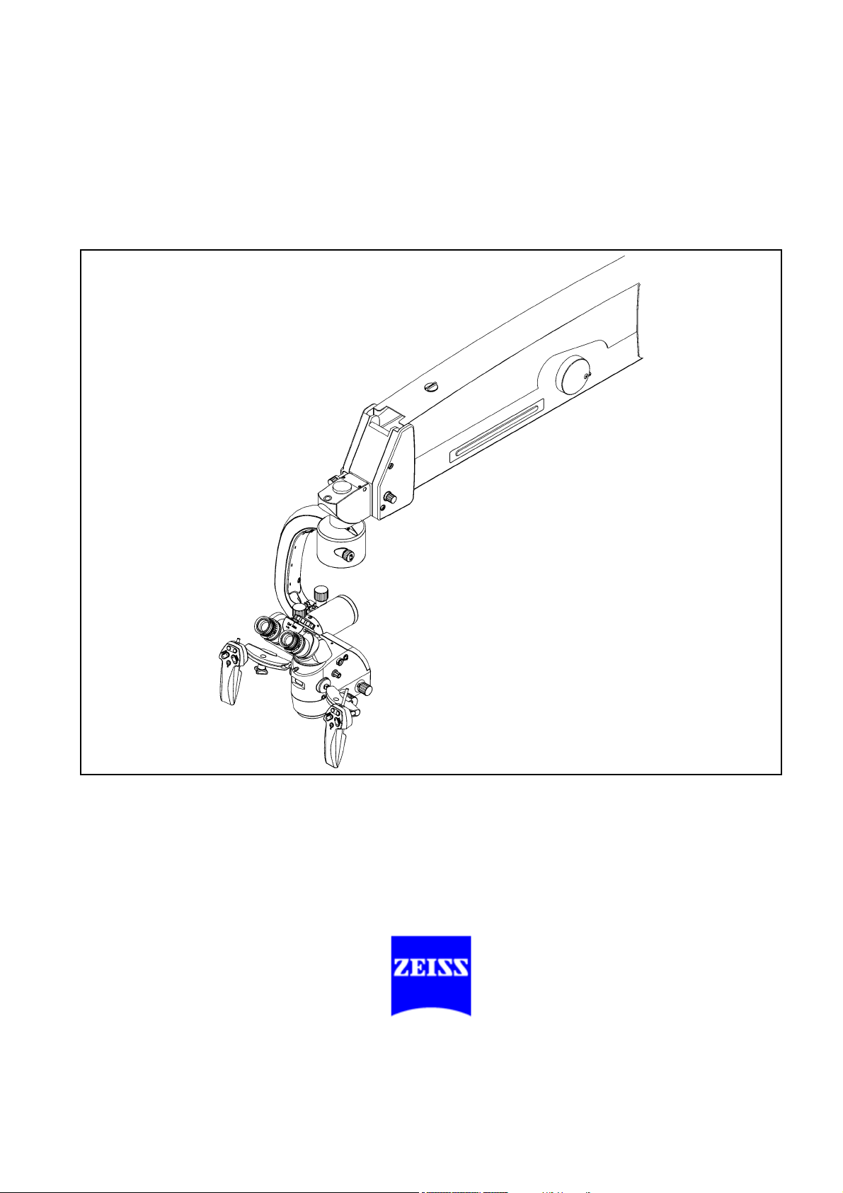
OPMI® VARIO
on S8, S81 & S88
Suspension Systems
Instructions for use
G-30-1607-en
Issue 5.0
Printed on 30. 01. 2009
Page 2
2
Key to symbols
Different symbols used in this manual draw your attention to safety aspects and useful tips. These symbols are explained in the following.
Warning!
The warning triangle indicates potential sources of danger which may
constitute a risk of injury for the user or a health hazard.
Caution:
The square indicates situations which may lead to malfunction, defects,
collision or damage of the instrument.
Note:
The hand provides hints on the use of the instrument or other tips for the
user.
®
OPMI
is a registered trademark of Carl Zeiss Surgical GmbH.
G-30-1607-en OPMI® VARIO on S8, S81 & S88 Suspension Systems Issue 5.0
Printed on 30. 01. 2009
Page 3

Contents
3
– Key to symbols 2
Functions at a glance 7
– OPMI® VARIO 8
– S88 floor stand 10
– S88 floor stand with lifting column 12
– S8 ceiling mount 14
– S81 ceiling mount 16
Safety 19
– Notes on installation and use 21
– Safety devices of the suspension systems 28
– Warning labels and notes 38
Description 47
OPMI® VARIO surgical microscope 50
– Intended use 50
– Special properties 51
– Design 52
– Controls, displays, connections 54
– Binocular tubes and eyepieces 62
Xenon illumination system 66
Identical modules of the suspension systems 72
– Suspension arm 72
– Display field with control keys 74
S88 floor stand 76
– Intended use 76
– Description of the modules 77
– Design 78
– Stand base with column 80
– Connection panel 82
G-30-1607-en OPMI® VARIO on S8, S81 & S88 Suspension Systems Issue 5.0
Printed on 30. 01. 2009
Page 4

4
– Instrument tray (option) 84
– Video monitor (option) 86
S88 floor stand with lifting column 94
– Intended use 94
– Description of the modules 95
– Design 96
– Stand base with lifting column 98
– Connector panel 100
S8 ceiling mount 102
– Intended use 102
– Description of the modules 103
–Design 104
– Power switch with connector (option) 106
S81 ceiling mount 108
– Intended use 108
– Description of the modules 109
–Design 110
– Power switch, connector and socket (option) 112
VARIO surgical microscope on S88 floor stand 114
– Intended use 114
–Design 114
VARIO surgical microscope on S88 floor stand
with lifting column 116
– Intended use 116
–Design 116
VARIO surgical microscope on S8 ceiling mount 118
– Intended use 118
–Design 118
VARIO surgical microscope on S81 ceiling mount 120
– Intended use 120
–Design 120
Foot control panel (option) 122
– Intended use 122
–Design 122
G-30-1607-en OPMI® VARIO on S8, S81 & S88 Suspension Systems Issue 5.0
Printed on 30. 01. 2009
Page 5

– Foot control panel with 14 functions 124
– Foot control panel with 8 functions 125
Preparations 127
Attaching the equipment 128
– Mounting the surgical microscope 128
– Attaching accessories 130
– Mounting the tube and eyepieces 132
Connections 134
– Connecting the surgical microscope 134
– Mounting the light guide 134
– Aligning the X-Y coupling 138
– Strain relief device on S88 floor stand 140
5
– Connecting the S88 floor stand 142
Adjusting the supension system 144
– S88 floor stand with lifting column Setting the ergonomic working height 144
– Adjusting the balance setting of the suspension arm 146
– Adjusting the limit of downward movement 148
– Positioning the S8 ceiling mount 150
Settings on the control and display panel 153
– Adjusting the suspension system 153
Balancing the surgical microscope 154
Adjusting the surgical microscope 156
Surgical microscope with a laser micromanipulator 157
Relocating the system 160
Operation 163
Checklist 164
Positioning the S88 floor stand 168
Using the display and key field 170
– General functions 170
– OPMI Vario on the suspension system, user interface
with SpeedFokus option 174
Procedure 194
G-30-1607-en OPMI® VARIO on S8, S81 & S88 Suspension Systems Issue 5.0
Printed on 30. 01. 2009
Page 6

6
What to do in an emergency 196
– Failure of a xenon lamp 196
– Failure of lamp control 200
– Failure of the zoom function 201
– Failure of the focusing function 202
– Failure of magnetic brakes 203
Maintenance / Further information 205
– Trouble-shooting 206
– Changing the xenon lamp module 214
– Adjusting the monitor arm 218
– Magnifications / Fields of view 220
– Care of the unit 222
– Sterilization 223
– Disinfecting the control keys 224
– Ordering data 226
– Spare parts 230
– Accessories 231
– Disposal 233
Technical data 235
– Technical data of OPMI VARIO 237
– Technical data of S88 floor stand 238
– Technical data of S88 floor stand with lifting column 240
– Technical data of S8 ceiling mount 246
– Technical data of S81 ceiling mount 250
– Ambient requirements 253
– CE conformity 253
– Changes to the system 253
Index 255
G-30-1607-en OPMI® VARIO on S8, S81 & S88 Suspension Systems Issue 5.0
Printed on 30. 01. 2009
Page 7

Functions at a glance 7
Functions at a glance
OPMI® VARIO 8
S88 floor stand 10
S88 floor stand with lifting column 12
S8 ceiling mount 14
S81 ceiling mount 16
G-30-1607-en OPMI® VARIO on S8, S81 & S88 Suspension Systems Issue 5.0
Printed on 30. 01. 2009
Page 8

8 Functions at a glance
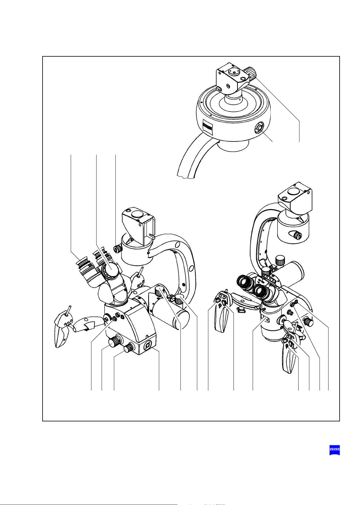
OPMI® VARIO
1 Adjusting the eyecup and the prescription page 64
2 Adjusting the interpupillary distance page 62
3 Adjusting the friction of vertical adjustment page 54
4 Recentering the X-Y coupling page 60
5 Adjusting the friction of the OPMI® axis of rotation page 60
6 Manual zoom setting page 56
7 Manual focusing page 56
8 Manual setting of the illuminated field diameter page 56
9 Connecting the light guide page 134
10 Balance setting of the microscope's
front-to-back tilt
11 Balance setting of the microscope's
lateral tilt
12 Motorized focusing page 58
13 Motorized zoom setting page 58
14 Display of the magnification factor of
the zoom system
15 Releasing the magnetic brakes page 58
16 Programmable release buttons page 58
17 Switching off the electrical drive of the
focusing system
18 Connecting the mouth switch page 54
page 54
page 54
page 54
page 56
G-30-1607-en OPMI® VARIO on S8, S81 & S88 Suspension Systems Issue 5.0
Printed on 30. 01. 2009
Page 9
Functions at a glance 9
5
186
1 23 4
78 11 12 13 14 15 16 17910
G-30-1607-en OPMI® VARIO on S8, S81 & S88 Suspension Systems Issue 5.0
Printed on 30. 01. 2009
Page 10

10 Functions at a glance
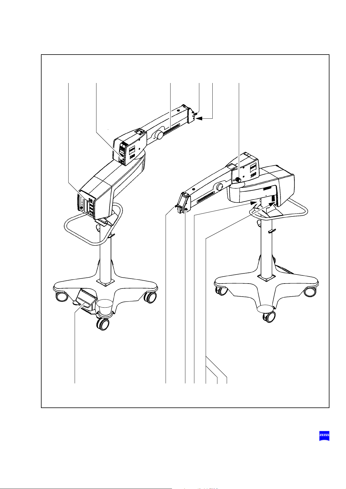
S88 floor stand
1 Control panel page 70
2 Illumination system page 66
3 Releasing the magnetic brakes of the suspension
system
4 Limiting the suspension arm's downward movement page 72
5 Removing/mounting the coupling for the
surgical microscope
6 Balance setting page 72
7 Locking the stand in position page 80
8 Locking the suspension arm in its horizontal position page 72
9 Connecting the foot control panel or hand switch,
plugging in the remote control connector
10 Rated voltage display page 82
11 Connector panel page 82
12 Switching on the suspension system page 82
page 72
page 72
page 82
G-30-1607-en OPMI® VARIO on S8, S81 & S88 Suspension Systems Issue 5.0
Printed on 30. 01. 2009
Page 11
Functions at a glance 11
12 43
56
7 4 8910,11,12
G-30-1607-en OPMI® VARIO on S8, S81 & S88 Suspension Systems Issue 5.0
Printed on 30. 01. 2009
Page 12
12 Functions at a glance
421 53
S88 floor stand with lifting column
Xenon illumination system
1 Selecting a filter page 68
2 Manual activation of backup bulb page 66
3 Resetting the counter page 68
4 Opening the lamp module page 68
5 Red segment is lit - backup bulb is in use page 66
6 Control panel
7 Lamp housing of xenon illumination system page 66
8 Unlocking the magnetic brakes of the suspension
system
9 Limiting the suspension arm's downward movement
10 Removing/mounting the coupling for the
surgical microscope
11 Balance setting
12 Locking the stand in position page 80
13 Raising/lowering the lifting column page 144
14 Locking the suspension arm in its horizontal position page 72
15 Connecting the foot control panel or hand switch,
Connecting the remote control connector
16 Rated voltage display page 82
17 Connector panel page 82
18 Turning on the suspension system page 82
page 72
page 72
page 82
G-30-1607-en OPMI® VARIO on S8, S81 & S88 Suspension Systems Issue 5.0
Printed on 30. 01. 2009
Page 13
Functions at a glance 13
67 98
10 11
12 13 9 14 15 16, 17, 18
G-30-1607-en OPMI® VARIO on S8, S81 & S88 Suspension Systems Issue 5.0
Printed on 30. 01. 2009
Page 14

14 Functions at a glance
S8 ceiling mount
1 Locking the suspension arm in its horizontal position page 72
2 Releasing the magnetic brakes of the suspension system page 72
3 Balance setting page 72
4 Illumination system page 66
5 Control panel (rotatable through 180° or 70°) page 70
6 Connecting the foot control panel or hand switch,
plugging in the remote control connector
7 Switching on the suspension system page 106
8 Releasing - moving - locking the lift arm page 104
9 Removing/mounting the coupling for the
surgical microscope
10 Setting the limit of downward travel page 72
page 106
page 72
G-30-1607-en OPMI® VARIO on S8, S81 & S88 Suspension Systems Issue 5.0
Printed on 30. 01. 2009
Page 15
Functions at a glance 15
102798
1
5623 4
G-30-1607-en OPMI® VARIO on S8, S81 & S88 Suspension Systems Issue 5.0
Printed on 30. 01. 2009
Page 16

16 Functions at a glance
S81 ceiling mount
1 Locking the suspension arm in its horizontal position page 72
2 Releasing the magnetic brakes of the suspension system page 72
3 Balance setting page 72
4 Illumination system page 66
5 Control panel (rotatable through 180° or 70°) page 70
6 Option: hand control panel socket for ceiling track mount page 112
7 Plugging in the remote control connector page 112
8 Connecting the foot control panel or hand switch page 112
9 Switching on the suspension system page 112
10 Removing/mounting the coupling for the
surgical microscope
11 Setting the limit of downward travel page 72
page 72
G-30-1607-en OPMI® VARIO on S8, S81 & S88 Suspension Systems Issue 5.0
Printed on 30. 01. 2009
Page 17
Functions at a glance 17
10 112
9
456123 87
G-30-1607-en OPMI® VARIO on S8, S81 & S88 Suspension Systems Issue 5.0
Printed on 30. 01. 2009
Page 18

18 Functions at a glance
G-30-1607-en OPMI® VARIO on S8, S81 & S88 Suspension Systems Issue 5.0
Printed on 30. 01. 2009
Page 19

Safety
Safety 19
Notes on installation and use 21
Safety devices of the suspension systems 28
Warning labels and notes 38
G-30-1607-en OPMI® VARIO on S8, S81 & S88 Suspension Systems Issue 5.0
Printed on 30. 01. 2009
Page 20

20 Safety
The device described in this manual has been designed and tested in accordance with Carl Zeiss safety standards as well as German and international standards. This guarantees a high degree of instrument safety.
The system described in this user manual has been designed in compliance with the requirements of:
–EN –IEC –UL –CSA
In accordance with Directive 93/42/EEC for medical devices, the complete quality management system of the company Carl Zeiss Surgical
GmbH, 73446 Oberkochen, Germany, has been certified by DQS Deutsche Gesellschaft zur Zertifizierung von Managementsystemen GmbH, a
notified body, under registration number 250758 MP23.
– As per Directive 93/42/EEC, the unit is a Class I instrument.
– For USA: FDA classification Class I.
We would like to provide you with information about safety aspects which
must be observed when handling this device. This chapter contains a
summary of the most important information concerning matters relevant
to instrument safety.
Important safety information has been incorporated in this manual and is
marked with a warning triangle accordingly. Please give this information
your special attention.
The correct use of the system is absolutely vital for safe operation. Please
make yourself totally familiar with the contents of this manual prior to startup of the instrument. Please also observe the user manuals of any additional equipment. Further information is available from our service department or from authorized representatives.
• Please observe all applicable accident prevention regulations.
• The instrument must be connected to a special emergency backup
line supply in accordance with the regulations or directives which apply in your country.
G-30-1607-en OPMI® VARIO on S8, S81 & S88 Suspension Systems Issue 5.0
Printed on 30. 01. 2009
Page 21

Safety 21
Notes on installation and use
Safe working order
• Do not operate the equipment contained in the delivery package in
– explosion-risk areas,
– the presence of inflammable anesthetics or volatile solvents such
as alcohol, benzine or similar chemicals.
• Do not station or use the instrument in damp rooms. Do not expose
the instrument to water splashes, dripping water or sprayed water.
• Switch off the unit at the power switch if you notice any smoke, sparks
or unusual noise. Do not use the unit until it has been repaired by our
service team.
• Do not place any fluid-filled containers on top of the instrument. Make
sure that no fluids can seep into the instrument.
• Do not force cable connections. If the male and female parts do not
readily connect, make sure that they are appropriate for one another.
If any of the connectors are damaged, have our service representative
repair them.
• Potential equalization: The instrument can be incorporated into potential equalization measures. For this purpose, contact our service department.
• Do not use a mobile phone in the vicinity of the equipment because
the radio interference can cause the equipment to malfunction. The effects of radio interference on medical equipment depend on a number
of various factors and are therefore entirely unforeseeable.
• Modifications and repairs on these instruments or instruments used
with them may only be performed by our service representative or by
other authorized persons.
• The manufacturer will not accept any liability for damage caused by
unauthorized persons tampering with the instrument; this will also forfeit any rights to claim under warranty.
• Over longer distances (e.g. removal, return for repair, etc), the instrument may only be transported in the original packaging or in special
return packaging. Please contact your dealer or the Carl Zeiss service
team.
• Use this instrument only for the applications described.
G-30-1607-en OPMI® VARIO on S8, S81 & S88 Suspension Systems Issue 5.0
Printed on 30. 01. 2009
Page 22

22 Safety
• Only use the instrument with the accessories supplied. Should you
wish to use other accessory equipment, make sure that Carl Zeiss or
the equipment manufacturer has certified that its use will not impair
the safety of instrument.
• Only personnel who have undergone training and instruction are allowed to use this instrument. It is the responsibility of the customer or
institution operating the equipment to train and instruct all staff using
the equipment.
• Keep the user's manuals where they are easily accessible at all times
for the persons operating the instrument.
• Never look at the sun through the binocular tube, the objective lens or
an eyepiece.
• Do not pull at the light guide cable, at the power cord or at other cable
connections.
• This instrument is a high-grade technological product. To ensure optimum performance and safe working order of the instrument, its safety
must be checked once every 12 months. We recommend having this
check performed by our service representative as part of regular maintenance work.
If a failure occurs which you cannot correct using the trouble-shooting
table, attach a sign to the instrument stating it is out of order and contact our service representative.
• Observe the labels showing the symbol "Risk of crushing“!
Notes on EMC (electromagnetic compatibility)
The system meets the EMC requirements of IEC 60601-1-2. During use
of the system, the precautionary measures concerning EMC listed below
must be observed.
Only use accessories that have been approved by Carl Zeiss for this
system.
Do not use any portable or mobile high frequency communication devices
in the vicinity of the system, as this may lead to an impairment of its function.
The system complies with the limits for a Class A device concerning radio
frequency emission. However, the possibility of interference to high frequency receiving devices (e.g. TV sets or radios) being used in the surroundings cannot be ruled out. If interference of this type occurs, please
inform your Carl Zeiss Service.
G-30-1607-en OPMI® VARIO on S8, S81 & S88 Suspension Systems Issue 5.0
Printed on 30. 01. 2009
Page 23

Safety 23
Connection of a laser micromanipulator
The link-up of a laser micromanipulator with the OPMI results in a medical
system for which the system manufacturer must meet the necessary requirements (approval, qualification, laser protection, etc.). Please note
the user manuals provided by the laser micromanipulator manufacturer
and laser manufacturer. Further information is available from our service
department or from authorized representatives.
G-30-1607-en OPMI® VARIO on S8, S81 & S88 Suspension Systems Issue 5.0
Printed on 30. 01. 2009
Page 24

24 Safety
Connection of navigation systems (option)
The Carl Zeiss components "Surgical microscope on suspension system"
can be integrated into an external navigation system. An optional navigation interface is available.
• The manufacturer of the external navigation system (system supplier)
is responsible for the following:
– Confirmation that his navigation systems have been tested and
– Meeting all requirements (approval, qualifications, etc.) for the
– Provision of all accompanying documents required.
certified for operation with the respective Carl Zeiss surgical microscope on a suspension system in accordance with the requirements specified in the Carl Zeiss interface description "Navigation
Interface for Carl Zeiss Surgical Microscopes".
medical system created through coupling via the navigation interface.
– Ensuring that the navigation system is only connected by person-
nel who have undergone appropriate training and instruction.
– Contacting the local Carl Zeiss representative for any inquiries that
may arise.
– Implementation of a procedure that guarantees the calibration of
the surgical microscope which is absolutely vital for the use of the
Carl Zeiss components "Surgical microscope on suspension system" in combination with a connected navigation system.
This allows the calibrated surgical microscope combined with the
navigation system to be used like an optical pointer with a variable
length (corresponds to the working distance).
– Conducting complete functional testing, alignment and calibration
(landmark test) of the navigation system after every subsequent installation or exchange of navigation system components
– Incorporation of a regularly changing icon in the data injection dis-
play of surgical microscopes equipped with a data injection system, i.e. the "heartbeat" of the navigation system must be
constantly visible for the user to permit data transmission errors to
be immediately detected.
• To check the accuracy of the overall system, perform the test specified
by the navigation system manufacturer, e.g. the landmark test, also
using the surgical microscope. This allows you to ensure that the stereotactic data has been correctly generated and transmitted to the navigation system without errors.
G-30-1607-en OPMI® VARIO on S8, S81 & S88 Suspension Systems Issue 5.0
Printed on 30. 01. 2009
Page 25

Safety 25
• Do not use any rotatable tube dovetail mounts when operating the surgical microscope with a connected navigation system. If mounts of this
type have been attached to the microscope, they must be carefully
locked in their central positions (tighten the knurled screw for rotation).
Requirements on the antenna design (non-Zeiss antennas)
• The antenna manufacturer must confirm that his antenna has been
tested and certified for operation with the respective Carl Zeiss surgical microscope on a suspension system in accordance with the requirements specified in the Carl Zeiss interface description
"Navigation Interface for Carl Zeiss Surgical Microscopes".
• The following requirements, in particular, apply to the antenna:
– The surgical microscope with accessories and the antenna must
not exceed the admissible total weight (see label or the chapter
"Technical data").
– The antenna must not project over the bottom edge of the micro-
scope body in the direction of the surgical field.
– The antenna must neither obstruct the movement and adjustability
of the accessories which can be used on the surgical microscope
(usually a stereo coobservation tube, a camera adapter, a face-toface tube for spinal surgery, a laser micromanipulator) nor collide
with these accessories.
– The antenna configuration must be implemented in such a way
that the localizer camera can always "see" the diodes or trackballs
when the surgical microscope and its accessories are in their usual
positions.
– When the system's internal antenna wiring is used, the EN60601-
1-2 standard (electromagnetic compatibility) must be complied
with.
– The output power of the LEDs or infrared LEDs (IRED) must al-
ways comply with the IEC 60825 laser safety standard, even in the
event of cable defects.
– The failure of one or several LEDs of the antenna may impair nav-
igation or lead to navigation failure. Take the necessary precautions.
G-30-1607-en OPMI® VARIO on S8, S81 & S88 Suspension Systems Issue 5.0
Printed on 30. 01. 2009
Page 26

26 Safety
Requirements for operation
• For ceiling mounts only: Our service staff or a qualified person appointed by us will install the system on ceiling anchors which have
been properly mounted by the construction engineers responsible.
These ceiling anchors must comply with the specifications contained
in our planning manual.
• Our service representative or an expert authorized by us will install the
system. Please ensure that the following requirements are met for further operation:
– All connecting components (details in the user's manual) which are
– All cables and plugs are in perfect condition.
– The voltage set on the instrument corresponds to the rated line
relevant to system safety have been properly connected, and the
screw connections have been firmly tightened.
voltage on the site of installation.
– The power cord has been plugged into a power outlet which has a
properly connected protective ground contact.
– The power cord being used is the one designed for use with this
system.
Before every use and after re-equipping the instrument
• Make sure that all ”Requirements for operation” are fulfilled.
• Go through the checklist.
• Re-attach or close any covers, panels or caps which have been removed or opened.
• Pay special attention to warning symbols on the instrument (triangular
warning signs with exclamation marks), labels and any parts such as
screws or surfaces painted red.
• Do not cover any ventilation openings.
For every use of the instrument
General
• Never operate the system unattended.
• Avoid looking directly into the light source, e.g. into the microscope objective lens or a light guide.
• When the illumination is on, the light guide must be connected at both
ends. Otherwise there is a risk of fire or burn injuries.
G-30-1607-en OPMI® VARIO on S8, S81 & S88 Suspension Systems Issue 5.0
Printed on 30. 01. 2009
Page 27

Safety 27
• Make sure that the instrument has been switched off before you
change the xenon lamp module. When switched on, the ignition system generates high voltage.
• The xenon illumination system is a high-intensity light source which if used improperly - can cause thermal injury to skin or tissue. Keep
the exposed tissue moist and provide sufficient irrigation. Carefully
monitor the effects of the illumination on the tissue, in particular in the
following cases:
– during prolonged procedures on skin and tissue using objective
lenses with a short focal length (short working distance),
– during procedures on tissue with a low blood supply,
– with high brightness settings of the xenon lamp.
• Since the xenon lamp provides high light intensity and generates light
with a spectrum similar to daylight, it must not be used for ophthalmic
applications.
• Any kind of radiation has a detrimental effect on biological tissue.This
also applies to the light illuminating the surgical field. Please therefore
reduce the brightness and duration of illumination on the surgical field
to the absolute minimum required.
S88 floor stand
• Using the locking pedal on the base, secure the stand in position.
Make sure that the stand is stable and cannot roll away.
After every use of the instrument
• Always use the main power switch of the instrument to turn it off.
• The main power switch must always be turned off when the instrument
is not in use.
G-30-1607-en OPMI® VARIO on S8, S81 & S88 Suspension Systems Issue 5.0
Printed on 30. 01. 2009
Page 28

28 Safety
Safety devices of the suspension systems
1 Release bar
Allows non-sterile persons to release the magnetic brakes of the suspension system.
2 Adjustment screw for limiting the downward travel
Use this screw to set the minimum vertical distance (working distance)
from the surgical field. Check this setting before
dure.
3 Locking knob
for locking the suspension arm in its horizontal position.
Before removing or attaching a unit (microscope, tube, etc.), move the
suspension arm into a horizontal position. Pull out the locking knob
and turn it clockwise or counterclockwise through 180°, while slightly
moving the suspension arm up and down until the lock engages.
When locked, the suspension arm can no longer suddenly spring upward when insufficient weight is attached. After attaching a unit, perform the balancing procedure.
each surgical proce-
G-30-1607-en OPMI® VARIO on S8, S81 & S88 Suspension Systems Issue 5.0
Printed on 30. 01. 2009
Page 29
Safety 29
1
1
2
3
G-30-1607-en OPMI® VARIO on S8, S81 & S88 Suspension Systems Issue 5.0
Printed on 30. 01. 2009
Page 30

30 Safety
Stand lifting column
1 Key
to set the optimum viewing height of the surgical microscope or for
downward movement into the transport position.
As long as you keep switch (1) pressed down, the lifting column (2) in
the stand base moves upwards or downwards, depending on the position of the switch. When you release the switch, the lifting column
stops immediately.
– Before raising or lowering the suspension system, make sure that
there is sufficient clearance from other objects so that any collision is
avoided.
Warning!
– Do not
activate the lifting column during surgery!
– Do not
use the lifting column for focusing.
– When using the fundus imaging system which is installed between the
surgical microscope and the patient, make sure that the patient is neither put at risk nor injured
– by the motorized movement of the lifting column,
– by the motorized focusing system,
– by the movement of the suspension arm.
G-30-1607-en OPMI® VARIO on S8, S81 & S88 Suspension Systems Issue 5.0
Printed on 30. 01. 2009
Page 31

Safety 31
1
2
G-30-1607-en OPMI® VARIO on S8, S81 & S88 Suspension Systems Issue 5.0
Printed on 30. 01. 2009
Page 32

32 Safety
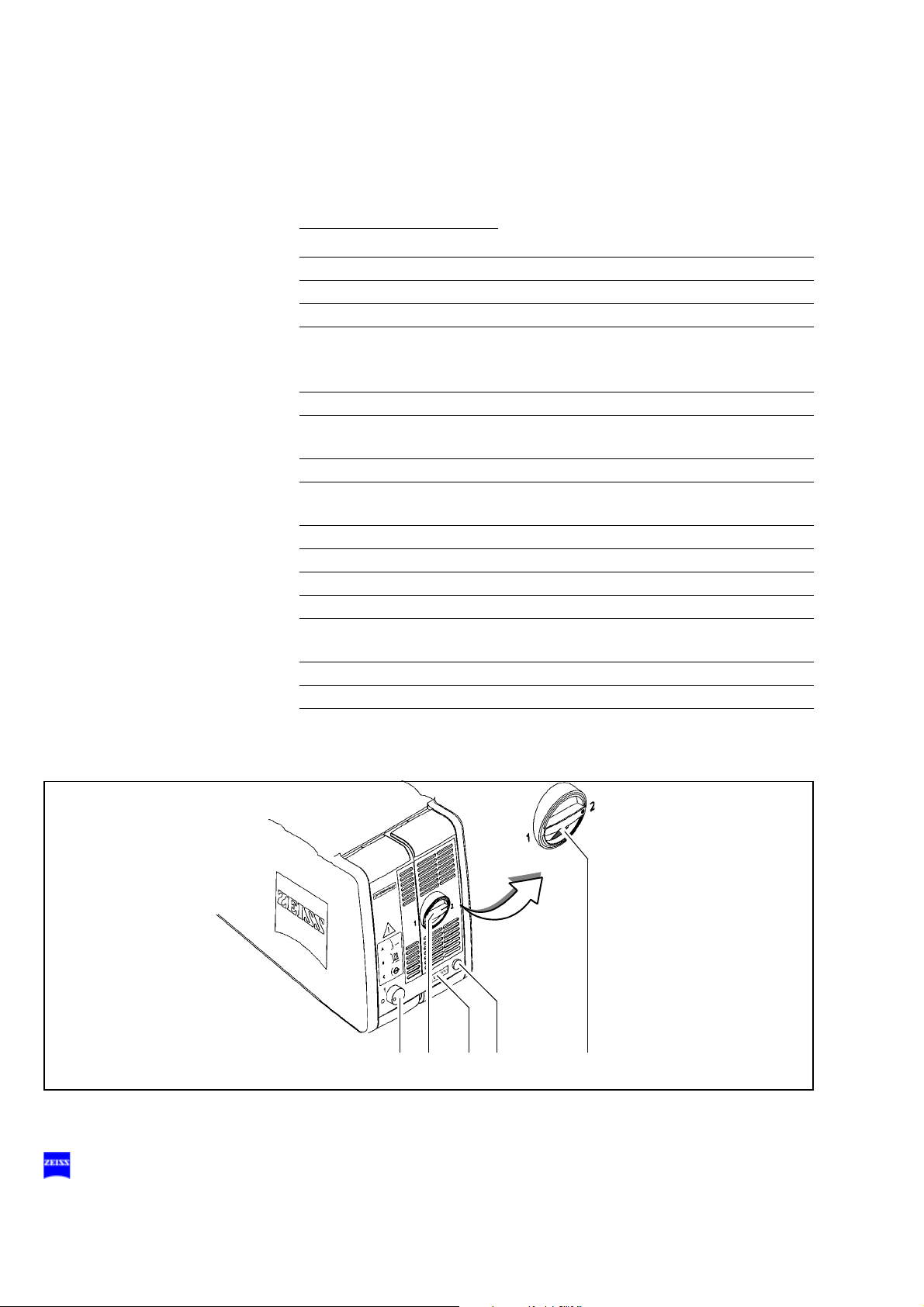
Xenon illumination system
Warning!
The xenon lamp has a limited service life of 500 h.
If used beyond its maximum service life, the xenon lamp may explode.
• Replace the xenon lamp in good time.
• Reset the service hour counter to "0" after replacing the lamp.
Warning!
Lamp rupture (audible as a loud bang) may lead to jamming of the lamp
module and/or failure of the electronics modules.
• Before opening the lamp housing, make sure that the system is moved
to a position where neither the patient nor the user is put at risk by falling items.
• Do not continue using the system if the lamp module is jammed or the
illumination is no longer operational due to defective electronics modules. Inform our service department.
1 Switching to the backup lamp
The lamp module contains two xenon lamps. The second bulb is used
as a backup bulb which must be swung into the illumination beam path
if the first bulb fails.
• If the xenon bulb fails, open the lamp module as follows: Press
button (7). The lamp module is slightly ejected.
G-30-1607-en OPMI® VARIO on S8, S81 & S88 Suspension Systems Issue 5.0
Printed on 30. 01. 2009
Page 33

Safety 33
3
4
7
1
2
25 6
G-30-1607-en OPMI® VARIO on S8, S81 & S88 Suspension Systems Issue 5.0
Printed on 30. 01. 2009
Page 34

34 Safety
• Pull out the lamp module as far as it will go.
• Turn knob (1) through 180° until it snaps in place. This moves the
backup lamp into the illumination beam path.
• Push the lamp module all the way back into the lamp housing.
• Reset service hour counter (6) to "0". Use a pointed object and press
it into the recess of reset button (5).
2 Indicator: backup lamp is in use
When the red segment in knob (1) lights up, the backup bulb is in use.
Note:
If the first bulb has failed and the backup bulb is in use, make sure to
have a backup lamp module at hand as a precaution.
3 Yellow indicator lamp
Lights when the bulb has failed, or if the lamp module is defective.
After activation and ignition of the backup bulb, the yellow indicator
lamp turns off again.
4 Manual function
When the manual function has been activated, all electrical control
systems are disabled. The bulb brightness is automatically adjusted to
a fixed setting.
G-30-1607-en OPMI® VARIO on S8, S81 & S88 Suspension Systems Issue 5.0
Printed on 30. 01. 2009
Page 35

Safety 35
3
4
7
1
2
25 6
G-30-1607-en OPMI® VARIO on S8, S81 & S88 Suspension Systems Issue 5.0
Printed on 30. 01. 2009
Page 36

36 Safety
Manual function
1 Manual key
The Manual key permits you to switch to manual operation. The motorized control functions of the surgical microscope are deactivated.
The lamp brightness is automatically adjusted to a fixed setting, the
value being shown in the first display section.
When the manual mode is activated, the yellow LED is lit and the word
"MANUAL" blinks in the third display section.
The surgical microscope can no longer be operated via the foot control
panel, the handgrips or the display and key field.
In the manual mode, you can only switch the illumination on and off on
the foot control panel and release the magnetic brakes by pressing the
appropriate key on the surgical microscope.
The manual mode is retained even if you turn the power switch of the
instrument off and on again.
Press the Manual key once again to reactivate electronic control; the
display in the display and key field then returns to the basic mode.
G-30-1607-en OPMI® VARIO on S8, S81 & S88 Suspension Systems Issue 5.0
Printed on 30. 01. 2009
Page 37

Safety 37
1
G-30-1607-en OPMI® VARIO on S8, S81 & S88 Suspension Systems Issue 5.0
Printed on 30. 01. 2009
Page 38

38 Safety
Warning labels and notes
Caution:
Observe all warning labels and notes!
If any label is missing on your instrument or has become illegible, please
contact us or one of our authorized representatives. We will supply the
missing labels.
OPMI VARIO
G-30-1607-en OPMI® VARIO on S8, S81 & S88 Suspension Systems Issue 5.0
Printed on 30. 01. 2009
Page 39

000000-0000-000
Safety 39
G-30-1607-en OPMI® VARIO on S8, S81 & S88 Suspension Systems Issue 5.0
Printed on 30. 01. 2009
Page 40

40 Safety
1
OPHTHALMOLOGY
Suspension systems - xenon illumination system
G-30-1607-en OPMI® VARIO on S8, S81 & S88 Suspension Systems Issue 5.0
Printed on 30. 01. 2009
Page 41

Safety 41
176164
S88 floor stand
G-30-1607-en OPMI® VARIO on S8, S81 & S88 Suspension Systems Issue 5.0
Printed on 30. 01. 2009
Page 42

42 Safety
S88 floor stand with instrument tray option
G-30-1607-en OPMI® VARIO on S8, S81 & S88 Suspension Systems Issue 5.0
Printed on 30. 01. 2009
Page 43

Safety 43
176164
S88 floor stand with lifting column
G-30-1607-en OPMI® VARIO on S8, S81 & S88 Suspension Systems Issue 5.0
Printed on 30. 01. 2009
Page 44

44 Safety
176164
S8 ceiling mount
G-30-1607-en OPMI® VARIO on S8, S81 & S88 Suspension Systems Issue 5.0
Printed on 30. 01. 2009
Page 45

Safety 45
S81 ceiling mount
G-30-1607-en OPMI® VARIO on S8, S81 & S88 Suspension Systems Issue 5.0
Printed on 30. 01. 2009
Page 46

46 Safety
G-30-1607-en OPMI® VARIO on S8, S81 & S88 Suspension Systems Issue 5.0
Printed on 30. 01. 2009
Page 47

Description
Description 47
OPMI® VARIO surgical microscope 50
Intended use 50
Special properties 51
Design 52
Controls, displays, connections 54
Binocular tubes and eyepieces 62
Xenon illumination system 66
Identical modules of the suspension systems 72
Suspension arm 72
Display field with control keys 74
S88 floor stand 76
Intended use 76
Description of the modules 77
Design 78
Stand base with column 80
Connection panel 82
Instrument tray (option) 84
Video monitor (option) 86
S88 floor stand with lifting column 94
Intended use 94
Description of the modules 95
Design 96
Stand base with lifting column 98
Connector panel 100
S8 ceiling mount 102
Intended use 102
G-30-1607-en OPMI® VARIO on S8, S81 & S88 Suspension Systems Issue 5.0
Printed on 30. 01. 2009
Page 48

48 Description
Description of the modules 103
Design 104
Power switch with connector (option) 106
S81 ceiling mount 108
Intended use 108
Description of the modules 109
Design 110
Power switch, connector and socket (option) 112
VARIO surgical microscope on S88 floor stand 114
Intended use 114
Design 114
VARIO surgical microscope on S88 floor stand
with lifting column 116
Intended use 116
Design 116
VARIO surgical microscope on S8 ceiling mount 118
Intended use 118
Design 118
VARIO surgical microscope on S81 ceiling mount 120
Intended use 120
Design 120
Foot control panel (option) 122
Intended use 122
Design 122
Foot control panel with 14 functions 124
Foot control panel with 8 functions 125
G-30-1607-en OPMI® VARIO on S8, S81 & S88 Suspension Systems Issue 5.0
Printed on 30. 01. 2009
Page 49

Description 49
G-30-1607-en OPMI® VARIO on S8, S81 & S88 Suspension Systems Issue 5.0
Printed on 30. 01. 2009
Page 50

50 Description
OPMI® VARIO surgical microscope
Intended use
The OPMI® VARIO surgical microscope has been designed for reconstructive and plastic surgery, for neurosurgery and multidisciplinary use,
i.e. the device meets the special requirements made on a surgical microscope in these disciplines.
Warning!
If the xenon light source is used, the unit must not be used in ophthalmic
applications. Severe injury to the patient's eye is possible.
G-30-1607-en OPMI® VARIO on S8, S81 & S88 Suspension Systems Issue 5.0
Printed on 30. 01. 2009
Page 51

Special properties
Description 51
The apochromatic optics of the OPMI® VARIO surgical microscope provide superb optical quality. The microscope image displays optimum contrast and excellent detail recognition along with a large depth of field. An
integrated, motorized Varioskop objective lens allows the working distance to the surgical field to be adjusted between 200 and 415 mm. A
motorized zoom system with a 1:6 ratio provides continuous magnification adjustment. Various tubes and accessories from our range of accessories can be mounted on the standard tube port.
The support arm of the unit is provided with a balancing system; all axes
of the arm are provided with magnetic brakes. Handgrips allow reliable
maneuvering of the unit and the operation of major functions.
If the unit is operated on an S8/S81 suspension system, further useful
functions are available:
– the magnetic brakes for almost effortless positioning,
– brightness control via the foot control panel,
– reset for XY coupling (option), focus and zoom,
– user defined basic settings for a maximum of nine users:
– lamp brightness
– speed for focusing, zoom and XY coupling
– programmable buttons on the foot control panel for focus memory, XY
reset (option), zoom memory, camera release, triggering of an AUX
signal.
G-30-1607-en OPMI® VARIO on S8, S81 & S88 Suspension Systems Issue 5.0
Printed on 30. 01. 2009
Page 52

52 Description
Design
The OPMI® VARIO surgical microscope comprises the following modules:
1 Coupling
for mounting the surgical microscope on the suspension system.
2 Support arm for surgical microscope
3 Balancing system including magnetic brakes
This system allows balancing of the surgical microscope. When the
magnetic brakes are released the surgical microscope can be positioned almost effortlessly.
4 Handgrips
for moving the surgical microscope. The buttons on the handgrips permit you to control major microscope functions such as releasing/locking the magnetic brakes, focusing, zoom setting.
5 Microscope body
The apochromatic optics of the microscope provide superb optical
quality. The microscope image displays optimum contrast and excellent detail recognition along with a large depth of field. The 1:6 ratio
zoom system allows the magnification of the overall system to be set
as required by the surgical procedure.
6 Magnetic brake
for the vertical axis.
G-30-1607-en OPMI® VARIO on S8, S81 & S88 Suspension Systems Issue 5.0
Printed on 30. 01. 2009
Page 53

Description 53
1
2
3
4
6
3
5
G-30-1607-en OPMI® VARIO on S8, S81 & S88 Suspension Systems Issue 5.0
Printed on 30. 01. 2009
Page 54

54 Description
Controls, displays, connections
1 Friction adjustment of the vertical axis
Use this knob to adjust the friction of the vertical axis as required.
2 Balance setting of the lateral tilt motion
Use this knob to adjust the balance setting of the lateral tilt motion.
3 Balance setting of the front-to-back tilt motion
Use this knob to adjust the balance setting of the front-to-back tilt motion.
4 Dust cover
5 Mouth switch socket
You can use the mouth switch to release or lock the magnetic brakes
of the suspension system used.
6 Display window
for reading off the magnification factor γ of the zoom system.
G-30-1607-en OPMI® VARIO on S8, S81 & S88 Suspension Systems Issue 5.0
Printed on 30. 01. 2009
Page 55

Description 55
6
1
3
4
2
5
G-30-1607-en OPMI® VARIO on S8, S81 & S88 Suspension Systems Issue 5.0
Printed on 30. 01. 2009
Page 56

56 Description
7 Focus stop button
This button permits you to deactivate the electrical drive of the focusing system. After you have pressed the focus stop button, you can
only focus manually on the surgical field using knob (9). The focus
stop button is lit. To release the stop, press the focus stop button again
(light in the button goes out).
The use of a micromanipulator for laser applications is described in
the section "Surgical microscope with laser micromanipulator", page
157.
8 Zoom knob
Use this knob for manual setting of the magnification.
9 Focusing knob
for manual setting of the image definition (focus, working distance)
10 Illuminated-field knob
for manual setting of the illuminated-field diameter.
11 Socket for S light guide
Insert the S light guide into the socket until it snaps in.
G-30-1607-en OPMI® VARIO on S8, S81 & S88 Suspension Systems Issue 5.0
Printed on 30. 01. 2009
Page 57

Description 57
7
8
910 11
G-30-1607-en OPMI® VARIO on S8, S81 & S88 Suspension Systems Issue 5.0
Printed on 30. 01. 2009
Page 58

58 Description
12 Freely programmable release buttons
Specific functions of the suspension system can be assigned to these
buttons, e. g.: increasing / reducing brightness etc.
13 Zoom release button
for setting the magnification factor from 0.4x 2.4x.
14 Focus release button
for continuous focusing within the working distance of 200 to 415 mm.
15 Release button for magnetic brakes
The magnetic brakes of the surgical microscope and suspension
system are released for as long as you press this button.
16 Locking the handgrips in position
Using this screw, you can lock each handgrip in almost any position.
You can swing the handgrips backward by 180° to permit a second
surgeon to operate the microscope in the 180° position.
17 Cable holder
Warning!
To ensure almost effortless guidance of the surgical microscope, the surgical microscope and the suspension system used (if provided) must be
correctly balanced.
If the system is in an extremely unbalanced state, the unit can move uncontrollably out of position. For this reason, hold the surgical microscope
tightly at its handgrips before releasing the magnetic brakes.
G-30-1607-en OPMI® VARIO on S8, S81 & S88 Suspension Systems Issue 5.0
Printed on 30. 01. 2009
Page 59

Description 59
12
14
15
13
16
17
G-30-1607-en OPMI® VARIO on S8, S81 & S88 Suspension Systems Issue 5.0
Printed on 30. 01. 2009
Page 60

60 Description
X-Y coupling (option)
Note:
• The OPMI® VARIO can be equipped (and also retrofitted) with an X-Y
coupling (2). Our service team or an authorized person will install the
X-Y coupling for you.
The X-Y coupling allows motorized fine positioning of the surgical microscope in a horizontal plane. The range of travel is 40 mm x 40 mm. The
speed of travel can be set on the display field of the suspension system.
The X-Y coupling is provided with a recentering mechanism. When you
press button (3), the X-Y coupling moves back into its center position.
You can also trigger the recentering function using the freely programmable buttons on the handgrips or foot control panel.
Knob (1) permits you to adjust the friction of the microscope's rotary axis.
See also: Preparations for use / Aligning the X-Y coupling, page 138.
G-30-1607-en OPMI® VARIO on S8, S81 & S88 Suspension Systems Issue 5.0
Printed on 30. 01. 2009
Page 61

Description 61
2
3
1
G-30-1607-en OPMI® VARIO on S8, S81 & S88 Suspension Systems Issue 5.0
Printed on 30. 01. 2009
Page 62

62 Description
Binocular tubes and eyepieces
180° tiltable tube
1 PD adjustment knob
The correct position has been reached when the two eyepiece images
merge into one. You can read off the interpupillary distance set on the
adjustment knob.
2 180° tiltable tube
3 Eyepiece mount
45° inclined tube
4 45° inclined tube
5 PD adjustment knob
The correct position has been reached when the two eyepiece images
merge into one. You can read off the interpupillary distance set on the
adjustment knob.
6 Eyepiece mount
G-30-1607-en OPMI® VARIO on S8, S81 & S88 Suspension Systems Issue 5.0
Printed on 30. 01. 2009
Page 63

Description 63
4
5
1
2
3
6
G-30-1607-en OPMI® VARIO on S8, S81 & S88 Suspension Systems Issue 5.0
Printed on 30. 01. 2009
Page 64

64 Description
Widefield eyepieces with magnetic coupling
Note:
When you remove these eyepieces from the tube, please note that they
are fitted with a magnetic coupling. When mounted, the eyepieces display
a very weak magnetic field, so that the usual rules for the handling of magnets must only be observed with eyepieces which have not been mounted
on the microscope:
• Do not place the eyepieces close to instruments where there is any
risk of magnetization.
• Do not place the eyepieces on sensitive electronic units such as infusion pumps, cardiac pace-makers, measuring instruments or magnetic data carriers such as disks, audiotapes and videotapes, or credit
cards.
• Always store eyepieces not used in their original packaging.
1 Eyecup
Always adjust the eyecups in such a way that you can see the full field
of view.
– Viewing with eyeglasses: Screw in the eyecups all the way.
– Viewing without eyeglasses: Screw out the eyecups until you
see the full field of view.
2 Diopter adjustment ring
The eyepieces provide ametropia compensation between -8 D and
+5 D. Eyeglass wearers who perform surgery wearing their glasses
set the diopter adjustment ring to 0 D. Turn the ring until you have obtained the optimum setting. An integrated brake holds the ring in the
position set.
3 Diopter scale
for reading the prescription set.
G-30-1607-en OPMI® VARIO on S8, S81 & S88 Suspension Systems Issue 5.0
Printed on 30. 01. 2009
Page 65

Description 65
1
2
3
G-30-1607-en OPMI® VARIO on S8, S81 & S88 Suspension Systems Issue 5.0
Printed on 30. 01. 2009
Page 66

66 Description
Xenon illumination system
Warning!
The suspension system with xenon illumination must not
thalmic procedures.
The suspension system is equipped with a xenon illumination system for
fiber illumination. The xenon lamp generates light whose spectrum resembles that of natural daylight. Regardless of the brightness setting, the
color temperature of the light always remains the same. Normal daylight
film without any additional conversion filters can therefore be used for
photographic documentation. The lamp housing contains two xenon
lamps. The second lamp is used as a backup lamp which must be swung
into the illumination beam path should the first lamp fail.
Ventilation grid
Do not cover the ventilation grid! For example, drapes could be covering
the grid. This can cause the lamp modules to overheat and lead to lamp
failure.
be used for oph-
1 Lamp module
2 Manual activation of the backup bulb
• If the xenon bulb fails, open the lamp module as follows: Press
button (7). The lamp module is slightly ejected.
• Pull out the lamp module as far as it will go.
• Turn knob (2) 180° until it snaps in place. This moves the backup bulb
into the illumination beam path.
• Push the lamp module all the way back into the lamp housing.
• Reset service hour counter (5) to "0". Use a pointed object and press
it into the recess of reset button (6).
G-30-1607-en OPMI® VARIO on S8, S81 & S88 Suspension Systems Issue 5.0
Printed on 30. 01. 2009
Page 67

Description 67
2
4
3
1
6
3
7
5
G-30-1607-en OPMI® VARIO on S8, S81 & S88 Suspension Systems Issue 5.0
Printed on 30. 01. 2009
Page 68

68 Description
Note:
When inserting a new lamp module, make sure that the knob (2) is set
to "1“. If the first bulb fails, switch to the second bulb in logical sequence.
3 Indicator: backup bulb is in use
When the red segment in the knob (2) lights up, the backup bulb is in
use.
4 Filter selector knob
The filter knob has two positions:
0 no filter
1 Filter swung in
(No integrated filter in the standard configuration)
5 Counter
The counter records the service hours of the xenon light source.
• Change the xenon bulbs after about 500 hours of operation to prevent
them from exploding. Then reset the counter to "0" by pressing reset
button (6).
6 Reset button
The reset button resets the service hour counter to "0".
7 Opening the lamp module
When you press this button, the lamp module is slightly ejected.
• To change the bulb, pull out the lamp module as far as it will go. Turn
the knob (2) 180° until it snaps in place. This moves the backup bulb
into the illumination beam path.
Warning!
The xenon lamp has a limited service life of 500 h.
If used beyond its maximum service life, the xenon lamp may explode.
• Replace the xenon lamp in good time.
• Reset the service hour counter to "0" after replacing the lamp.
G-30-1607-en OPMI® VARIO on S8, S81 & S88 Suspension Systems Issue 5.0
Printed on 30. 01. 2009
Page 69

Description 69
2
4
3
1
6
3
7
5
G-30-1607-en OPMI® VARIO on S8, S81 & S88 Suspension Systems Issue 5.0
Printed on 30. 01. 2009
Page 70

70 Description
8 Brightness control
You can adjust the brightness using the two control keys on the control
panel.
Note:
The brightness of the xenon lamp can also be adjusted by pressing
the appropriate buttons on the foot control panel.
9 Yellow indicator lamp
Lights when the lamp has failed, or if the lamp module is defective.
After activation and ignition of the backup lamp, the yellow indicator
lamp goes out again.
Note:
If the first lamp has failed and the backup lamp is in use, make sure to
have a backup lamp module ready at hand as a precaution.
10 Green indicator lamp
Lights when the illumination has been switched on.
11 Selector switch:
Illumination is off.
Illumination is on.
Illumination can be switched on/off on the left-hand side of
the foot control panel.
Illumination can be switched on/off on the right-hand side of
the foot control panel.
Note:
You can adjust the selector in such a way that you can switch the illumination on/off on the right-hand and left-hand sides of the foot control
panel.
G-30-1607-en OPMI® VARIO on S8, S81 & S88 Suspension Systems Issue 5.0
Printed on 30. 01. 2009
Page 71

Description 71
8
11
9
10
0
,
7
G-30-1607-en OPMI® VARIO on S8, S81 & S88 Suspension Systems Issue 5.0
Printed on 30. 01. 2009
Page 72

72 Description
Identical modules of the suspension systems
Suspension arm
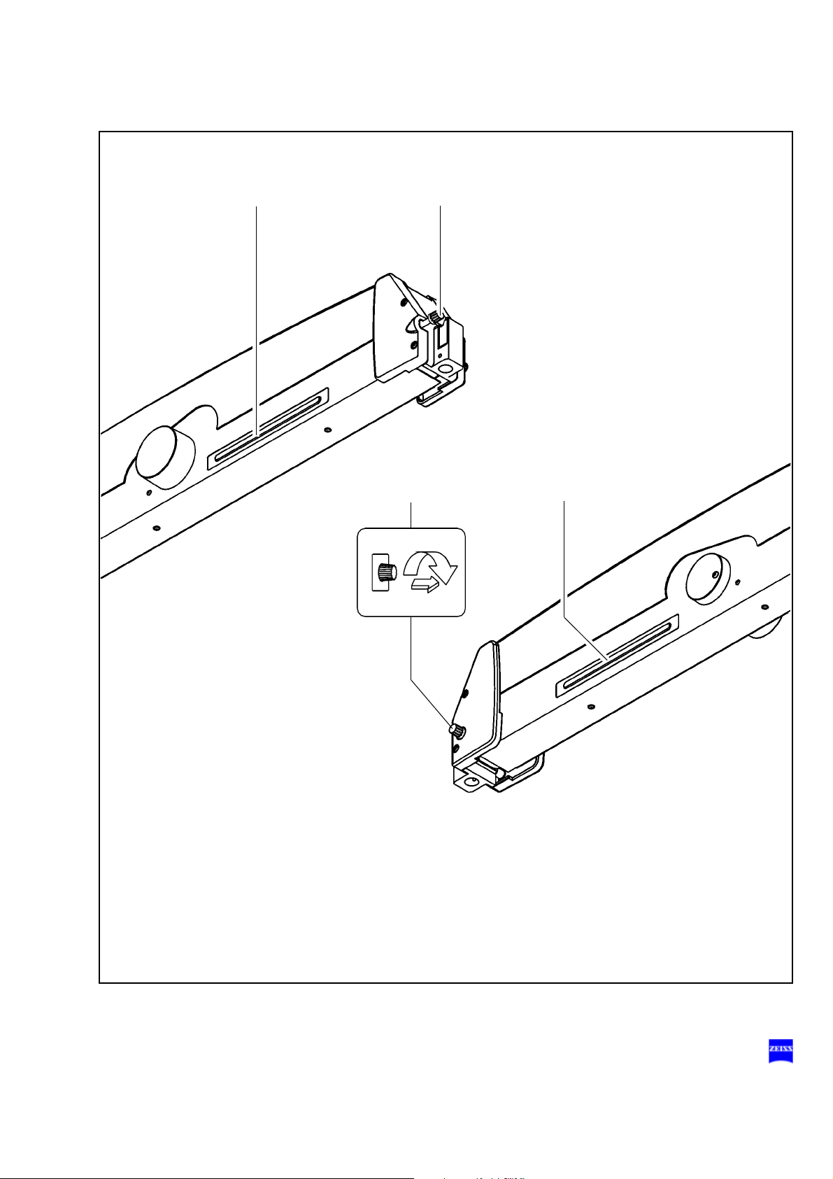
1 Lock of the cable duct
– For opening, turn a quarter turn clockwise or counterclockwise.
– For closing, press down and turn a quarter turn clockwise or coun-
terclockwise.
2 Adjustment screw for limiting downward movement
Use this screw to set the minimum vertical working distance from the
surgical field. Bring the surgical microscope into its working position.
Turn the adjustment screw for limiting downward movement clockwise
as far as it will go. Adjust the downward movement limitation before
each surgical procedure.
3 Balance setting screw
After mounting the surgical microscope including all
just the balance setting of the suspension arm using this screw. Balance setting is described in detail in chapter “Operation“.
4 Securing screw
for securing the OPMI
5 Locking knob
for locking the suspension arm in a horizontal position for mounting
the surgical microscope. This prevents the suspension arm from uncontrollably moving upward when insufficient weight is attached.
6 Release bar
Allows non-sterile persons to release the magnetic brakes of the suspension system.
Magnetic brake release buttons
The magnetic brake release buttons are located on the surgical microscope. For as long as you press one of these buttons, you can move the
articulated arm in all directions. When you let go of the button, the magnetic brakes will lock all axes in position at the same time.
®
coupling.
accessories, ad-
G-30-1607-en OPMI® VARIO on S8, S81 & S88 Suspension Systems Issue 5.0
Printed on 30. 01. 2009
Page 73

Description 73
12
5
3
4
6
6
G-30-1607-en OPMI® VARIO on S8, S81 & S88 Suspension Systems Issue 5.0
Printed on 30. 01. 2009
Page 74

74 Description
MODE
STORE MANUAL
USER
1
1
1.5
Xe
Basic mode
Display field with control keys
The display and control panel is integrated in the control unit.
The surgical microscope on the suspension system can be controlled either manually or electronically. The control software required for electronic control is installed in the electronics box of the suspension system.
You operate the software via the control and display panel, where you can
read off and reconfigure the current settings.
The control and display panel is structured as follows:
– Three display fields (LCD) with the associated keys "∇" and "Δ".
– One row of keys comprising the MODE, STORE and MANUAL keys,
and a yellow LED above the MANUAL key.
User interface
The user interface of the suspension system comprises three display
fields and keys located beside and below them.
A pair of keys "∇" and "Δ" has been assigned to every display field for
making the appropriate settings.
The control functions have been combined in several modes (menu
pages). The basic mode is always displayed in the normal operating
status.
The following is displayed in the basic mode:
– the current lamp brightness of lamp 1 (xenon) in the upper display
field,
– Xe for xenon in the middle display field,
– the current user ID in the lower display field.
Key row
Three keys and an LED are provided below the display fields.
Use the "MODE", "STORE" and "MANUAL" keys to select the different
control functions (modes).
"MODE" key and "STORE" key
The "MODE" and "STORE" keys permit you to access the different modes
of the user interface. For details, please see the chapter "Operation".
"STORE" key
Use the "STORE" key to save the current focus and zoom settings.
G-30-1607-en OPMI® VARIO on S8, S81 & S88 Suspension Systems Issue 5.0
Printed on 30. 01. 2009
Page 75

Description 75
"MANUAL" key
The "MANUAL" key permits you to switch to manual operation. For details, please see the chapter "Operation".
Yellow LED above the "MANUAL" key
The yellow LED is lit when you have switched to the manual mode.
G-30-1607-en OPMI® VARIO on S8, S81 & S88 Suspension Systems Issue 5.0
Printed on 30. 01. 2009
Page 76

76 Description
S88 floor stand
Intended use
The S88 floor stand is a carrier system for the surgical microscope. It is
used to power and control the motorized functions of the surgical microscope. The hallmarks of the floor stand are its superb mobility and easy
operation. Four steerable casters on the stand base permit easy positioning in the OR. The motorized functions of the surgical microscope can
be activated using a foot control panel.
Further useful functions include, for example:
– magnetic brakes for almost effortless positioning,
– brightness control via a foot control panel,
– reset of X-Y coupling, focus and zoom,
– user-defined basic settings for a maximum of nine users:
– speeds for focus, zoom and X-Y coupling
– and configurable buttons on the foot control panel for focus mem-
ory, XY inversion, camera release, swinging SDI in/out, triggering
an AUX signal.
Warning!
The suspension system with xenon illumination must not
thalmic procedures.
be used for oph-
G-30-1607-en OPMI® VARIO on S8, S81 & S88 Suspension Systems Issue 5.0
Printed on 30. 01. 2009
Page 77

Description 77
Description of the modules
The floor stand comprises an articulated arm, a stand column and a stand
base. The articulated arm comprises a carrier arm and a suspension arm.
The carrier arm contains the control unit with all electrical supply systems
required for the control of a motorized surgical microscope. These motorized functions can be activated using a foot control panel.
The suspension arm permits almost effortless positioning of the surgical
microscope. The spring force of the suspension arm can be varied in a
range from 8 to 20 kg, permitting reliable balancing of the microscope
even with heavy accessory equipment. The downward movement of the
suspension arm can be limited as required.
A maneuvering handle attached to the stand column is used to move the
stand and to attach the foot control panel. The stand column is provided
on its left and right with cable supports for winding up cables before the
unit is relocated. Four steerable casters on the stand base permit easy
positioning near the operating table. The stand base has been designed
in such a way that high stability is ensured even with unfavorable loading
of the stand. A locking pedal is provided to lock the floor stand quickly and
reliably into position.
Caution:
As the stand is very easy to maneuver, there is a tendency to underestimate its considerable weight. Therefore, move the stand slowly and carefully!
G-30-1607-en OPMI® VARIO on S8, S81 & S88 Suspension Systems Issue 5.0
Printed on 30. 01. 2009
Page 78

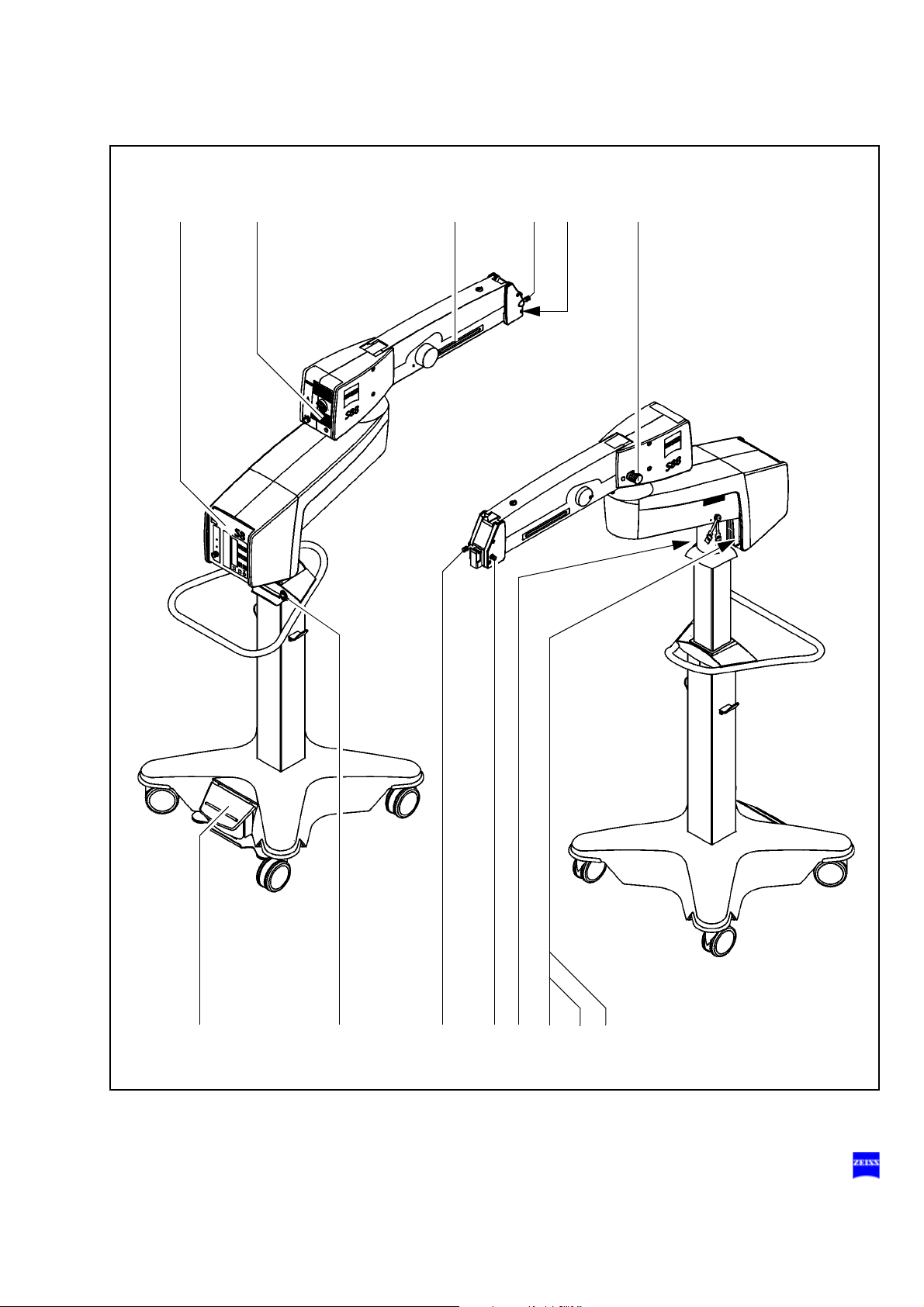
78 Description
Design
1 Control panel
2 Carrier arm
3 Xenon illumination system, see Seite 1
4 Suspension arm
5 Stand base
G-30-1607-en OPMI® VARIO on S8, S81 & S88 Suspension Systems Issue 5.0
Printed on 30. 01. 2009
Page 79

Description 79
1
3
2 4
5
G-30-1607-en OPMI® VARIO on S8, S81 & S88 Suspension Systems Issue 5.0
Printed on 30. 01. 2009
Page 80

80 Description
Stand base with column
1 Handle
for moving the stand.
2 Support
for hanging up the foot control panel during transport.
3 Cable support (2x)
for winding up the power cord and the cable of the foot control panel.
4 Cable deflectors
are provided to prevent cables on the floor from being run over and
damaged.
5 Locking pedal
Press once to lock the stand in position.
Press a second time to release the locking pedal.
6 Steerable casters
The four steerable casters on the stand base permit easy positioning
in the OR.
G-30-1607-en OPMI® VARIO on S8, S81 & S88 Suspension Systems Issue 5.0
Printed on 30. 01. 2009
Page 81

Description 81
1
2
5
6
3
4
4
4
G-30-1607-en OPMI® VARIO on S8, S81 & S88 Suspension Systems Issue 5.0
Printed on 30. 01. 2009
Page 82

82 Description
Connection panel
1 Remote socket
for triggering an AUX signal, e.g. to switch on/off an external device
operating at max. 24V/0.5A.
2 Connector for switching component
Possibility of connecting a foot control panel or operating chair with an
appropriate footswitch.
3 Potential equalization connector
4 Indicator window for rated voltage
The voltage shown here must correspond to the rated line voltage provided on the site of installation. You can adjust the sliding switch using
a suitable tool.
Warning!
Please observe the maximum current consumption of two power outlets
(5) and (6). Only connect medical devices approved by us to outlets (5)
and (6). When using other devices, make sure that safety is guaranteed
regarding admissible ground leakage currents. The admissible limit value
of the ground leakage current present in the suspension system's power
cord must not exceed 500 µA in compliance with EN60601-1/IEC 60601-
1. CSA/US certification in compliance with UL 60601-1 only allows a max-
imum ground leakage current of 300 µA.
5 Power outlet
for medical devices with a current consumption of max. 2 A.
Note:
The current of this power outlet is switched on/off using power
switch S2 (8).
6 Power outlet socket
for medical devices with a current consumption of max. 5 A.
7 Power inlet socket
8 Power switch S2
When the suspension system is on, the green indicator light in the
switch is lit.
G-30-1607-en OPMI® VARIO on S8, S81 & S88 Suspension Systems Issue 5.0
Printed on 30. 01. 2009
Page 83

Description 83
S2
4
5
6
7
8
2
3
9
1
9 Strain relief device
The strain relief device prevents inadvertent unplugging of the following electrical connections:
– power cable,
– connecting cable for foot control panel or operating chair with ap-
propriate footswitch.
G-30-1607-en OPMI® VARIO on S8, S81 & S88 Suspension Systems Issue 5.0
Printed on 30. 01. 2009
Page 84

84 Description
Instrument tray (option)
The S88 floor stand and the S88 floor stand with lifting column an be
equipped or retrofitted with an instrument tray. In the case of retrofitting,
our service staff or an authorized person will install the instrument tray on
your suspension system.
The instrument tray (1) can carry a maximum of 13 kg. The tray has been
designed, for example, for mounting MediLive Trio from Zeiss:
The MediLive Trio is attached to the instrument tray with the aid of two
stud bolts. (The four receptacles supplied with the instrument tray are not
required for mounting MediLive Trio.)
A second MediLiveTrio or other accessory equipment can be mounted on
the instrument tray using the strap provided. Please note the instrument
tray's maximum load capacity of 13 kg.
Warning!
• Make sure that the accessory equipment is positioned as securely as
possible on the instrument tray.
• Mount MediLive Trio on the instrument tray using the two stud bolts.
• If required, secure further accessory equipment on the tray using the
strap provided.
• Do not
• Remember there is a risk of collision and crushing when suspension
arm (2) is folded to its moving position. A "Risk of crushing" warning
label is therefore attached on the left and right of suspension arm (2).
• Please read the relevant user manual before starting up the accessory
equipment.
• Never pull or push at the accessory equipment (3) in order to move the
S88 floor stand. Always use handle (4) to move the S88 floor stand.
place a load of more than 13 kg on instrument tray (1).
G-30-1607-en OPMI® VARIO on S8, S81 & S88 Suspension Systems Issue 5.0
Printed on 30. 01. 2009
Page 85

Description 85
1
3
4
2
1
G-30-1607-en OPMI® VARIO on S8, S81 & S88 Suspension Systems Issue 5.0
Printed on 30. 01. 2009
Page 86

86 Description
Video monitor (option)
The S88 floor stand and the S88 floor stand with lifting column an be
equipped or retrofitted with a TFT monitor. In the case of retrofitting, our
service staff or an authorized person will install the TFT monitor on your
suspension system.
The TFT monitor (1) features a 15" screen and permits the scrub nurse
and other OR staff to follow the surgical procedure. For optimum viewing,
the TFT monitor can be precisely positioned using flexible arm (2).
Warning!
Risk of injury due to lowering of the TFT monitor!
• Ageing processes may lead to the loss of gas in the gas pressure
spring of the monitor's suspension arm, causing the TFT monitor to
move downward of its own accord.
• Compensate for the loss of gas by readjusting the gas pressure spring
as described on page 218.
If the TFT monitor continues to move downward, the gas pressure spring
is defective.
• Notify our service representative.
Warning!
Do not use the stored video sequences, video clips (cut sequences) and
single images for diagnostic purposes, as the video cameras and the
monitor have not been calibrated. The visualized images may therefore
include deviations in scale, color and shape.
This applies in particular if the sequences, clips or images are viewed on
a monitor outside the OR, as the transmission to a different monitor may
lead to changes in the display.
Note:
The background illumination of the LCD display has a limited service life.
If you notice that the display is getting darker or starts to flicker, contact
your Zeiss dealer.
G-30-1607-en OPMI® VARIO on S8, S81 & S88 Suspension Systems Issue 5.0
Printed on 30. 01. 2009
Page 87

Description 87
2
1
G-30-1607-en OPMI® VARIO on S8, S81 & S88 Suspension Systems Issue 5.0
Printed on 30. 01. 2009
Page 88

88 Description
Components
The principal component of the TFT monitor is the 15" screen which delivers flawless, sharp images even at low frame rates of 50 Hz.
The connectors and controls are located under cable cover (2) on the
back of the TFT monitor. To access the connectors and controls, proceed
as follows:
• Remove two screws (3) from cable cover (2) by turning them counterclockwise.
• Remove cable cover (2) by pushing it upward.
Controls
1 Auto Adjust button
The Auto Adjust function permits automatic image adjustment of the
TFT monitor to obtain a sharp, optimally positioned image. Perform
the automatic adjustment when initially starting up the TFT monitor or
after making any changes to the system.
Note:
– The Auto Adjust function can only be executed if a VGA signal
source is connected.
– Always use a normal camera image for automatic image adjust-
ment. Do not use the test image which is displayed directly after
power-on or when no camera head is connected.
G-30-1607-en OPMI® VARIO on S8, S81 & S88 Suspension Systems Issue 5.0
Printed on 30. 01. 2009
Page 89

Description 89
32 3
1
G-30-1607-en OPMI® VARIO on S8, S81 & S88 Suspension Systems Issue 5.0
Printed on 30. 01. 2009
Page 90

90 Description
Connector panel
2 Power supply
for power and voltage supply of the device.
Caution:
Only operate the device with the power cable included in the delivery
package.
3 DVI connector
DVI stands for Digital Video Interface and is the latest technology for
digital data transmission. The cable length for this connector must not
exceed 4.5 m.
Note:
We recommend the DVI connector for the connection of a camera, as
it delivers optimum image quality with minimum flicker. The DVI cable
is included in the delivery package.
4 VGA connector
VGA stands for Video Graphics Array and is an analog interface for
video data transmission between graphics cards and display devices.
5 S-Video connector
S-Video - also known as separate video or Y/C - is an analog interface
that transmits brightness and color information as separate signals.
This standard provides higher video image quality than Composite
Video. The maximum cable length for this connector should not exceed 10 m. For longer cables, please use the Composite Video connector.
6 Composite Video connector (1x cinch)
This is an analog interface that transmits the composite video signal
via a single channel (yellow cinch connector). This connector is particularly suitable for transmitting video signals over long distances.
7 Component connector (3x cinch)
This is an analog interface that transmits the component video signal
via three channels (red, yellow, green cinch connector). Each channel
transmits one of the primary colors.
G-30-1607-en OPMI® VARIO on S8, S81 & S88 Suspension Systems Issue 5.0
Printed on 30. 01. 2009
Page 91

Description 91
2 3 4 5 67
G-30-1607-en OPMI® VARIO on S8, S81 & S88 Suspension Systems Issue 5.0
Printed on 30. 01. 2009
Page 92

92 Description
Powering on the TFT monitor
To facilitate the operation of the TFT monitor, it is automatically activated
when the suspension system is switched on.
During the power-on process, the TFT monitor executes a power-on sequence in which the signals on the connectors (DVI, VGA, S-Video, Composite and Component) are checked. After detection of the signal available, the correct screen resolution and frame rate are set automatically.
Note:
If a signal source is present at the VGA connector, the image settings can
be optimized using the Auto Adjust function as described on page 88.
Aligining the video monitor
The best visualization is obtained when you are looking straight at the
screen of the TFT monitor.
• Swivel the monitor's carrier arm (1) and suspension arm (2) into the
horizontal position required.
Caution:
Take care not to damage the video cable!
Do not swivel the suspension arm beyond ±120°.
• Tilt the suspension arm (2) upward or downward until the required
height has been reached.
• Hold the upper corners of the TFT monitor and adjust it to the required
angle via ball joint (3).
Warning!
Risk of injury due to lowering of the TFT monitor!
• Ageing processes may lead to the loss of gas in the gas pressure
spring of the monitor's suspension arm, causing the TFT monitor to
move downward of its own accord.
• Compensate for the loss of gas by readjusting the gas pressure spring
as described on page 218.
If the TFT monitor continues to move downward, the gas pressure spring
is defective.
• Notify our service representative.
G-30-1607-en OPMI® VARIO on S8, S81 & S88 Suspension Systems Issue 5.0
Printed on 30. 01. 2009
Page 93

±90°
360°
90°
45°
2
1
3
Description 93
G-30-1607-en OPMI® VARIO on S8, S81 & S88 Suspension Systems Issue 5.0
Printed on 30. 01. 2009
Page 94

94 Description
S88 floor stand with lifting column
Intended use
The floor stand is a carrier system for Zeiss surgical microscopes for almost all surgical disciplines. It is used to power and control the motorized
functions of a surgical microscope. The hallmarks of the floor stand are its
superb mobility and easy operation. A motorized lifting column permits the
viewing height to be perfectly matched to the surgeon's requirements.
Four steerable casters on the stand base permit easy positioning in the
operating area. The motorized functions of the surgical microscope can
be controlled using a foot control panel or hand control panel.
Further useful functions include for example:
– the magnetic coupling for almost effortless positioning,
– fully automatic change of the halogen lamp,
– brightness control via the foot control panel,
– resetting the X-Y coupling, focus and zoom,
– user-defined basic settings for a maximum of nine users:
– Lamp brightness
– speeds for focus, zoom and X-Y coupling
– and configurable keys at the foot control panel for focus memory,
XY-inversion, camera triggering, swing in/out of SDI, triggering the
AUX signal.
Warning!
The suspension system with xenon illumination must not
thalmic procedures.
be used for oph-
G-30-1607-en OPMI® VARIO on S8, S81 & S88 Suspension Systems Issue 5.0
Printed on 30. 01. 2009
Page 95

Description 95
Description of the modules
The S88 floor stand comprises the articulated arm, the motorized stand
lifting column and the stand base. The articulated arm comprises a carrier
arm and a suspension arm.
The carrier arm contains the control unit with all electrical supply systems
required for the control of a motorized surgical microscope. You can control the motorized functions via a foot control panel or a hand control
panel.
The suspension arm permits almost effortless positioning of the surgical
microscope. The spring force of the suspension arm can be varied in a
range from 8 to 20 kg, permitting reliable balancing of the microscope
even with heavy accessory equipment. The downward movement of the
suspension arm can be limited as required.
The height of the stand column can be set via a motorized function. The
lifting column allows the continuous positioning of the surgical microscope
within a lifting range of 530 mm to set the optimum viewing height of the
microscope or to move downwards into the transport position. A maneuvering handle attached to the stand column is used to move the stand and
to attach the foot control panel. The stand column is provided on its left
and right with cable supports for winding up cables before the unit is relocated. Four steerable casters on the stand base permit easy positioning
near the operating table. The stand base has been designed in such a
way that high stability is ensured even with unfavorable loading of the
stand. A locking pedal permits the S( floor stand to be locked in position
quickly and reliably.
Note:
As the stand is very easy to maneuver, there is a tendency to underestimate its considerable weight. Therefore, move the stand slowly and carefully!
G-30-1607-en OPMI® VARIO on S8, S81 & S88 Suspension Systems Issue 5.0
Printed on 30. 01. 2009
Page 96

96 Description
Design
1 Control unit
2 Carrier arm
3 Lamp housing with Xenon illumination
4 Suspension arm
5 Motorized stand lifting column
6 Stand base
G-30-1607-en OPMI® VARIO on S8, S81 & S88 Suspension Systems Issue 5.0
Printed on 30. 01. 2009
Page 97

Description 97
1
3
2 4
5
6
G-30-1607-en OPMI® VARIO on S8, S81 & S88 Suspension Systems Issue 5.0
Printed on 30. 01. 2009
Page 98

98 Description
Stand base with lifting column
1 Lifting column
2 Handle
for moving the stand.
3 Support
for hanging up the foot control panel during transport.
4 Up/down switch
for setting the optimum viewing height of the surgical microscope, for
moving the system up into the standby position or down into the transport position.
As long as you keep switch (4) pressed, lifting column (1) in the stand
base moves upward or downward, depending on the switch position.
When you release the up/down switch, the lifting column stops immediately.
The switching technology causes a dead time of approx. 2 seconds at
the upper and lower end positions of the lifting column. After this time,
you can move in the opposite direction again by activating switch (2).
5 Cable deflectors
are provided to prevent cables on the floor from being run over and
damaged.
6 Locking pedal
Press once to lock the stand in position.
Press a second time to release the locking pedal.
7 Steerable casters
The four steerable casters on the stand base permit easy positioning
in the OR.
8 Cable support (2x)
for winding up the power cord and the cable of the foot control panel.
G-30-1607-en OPMI® VARIO on S8, S81 & S88 Suspension Systems Issue 5.0
Printed on 30. 01. 2009
Page 99

Description 99
1
2
3
8
4
6
7
5
5
5
G-30-1607-en OPMI® VARIO on S8, S81 & S88 Suspension Systems Issue 5.0
Printed on 30. 01. 2009
Page 100

100 Description
Connector panel
1 Remote control socket
for triggering an AUX signal, e.g. to switch on/off an external device
operating at max. 24V/0.5A.
2 Connector for switching component
Connection possibility for: a foot control panel, a hand control panel or
an operating chair with an appropriate foot switch.
3 Potential equalization bolt
4 Indicator window for rated voltage
The voltage shown here must correspond to the rated line voltage provided on the site of installation. You can adjust the sliding switch using
a suitable tool.
Warning!
Please observe the maximum current consumption of two power outlets
(4) and (5). Only connect medical devices approved by us to outlets (4)
and (5). When using other instruments, make sure that safety is guaranteed regarding admissible ground leakage currents. The admissible limit
value of the ground leakage current present in the suspension system's
power cord must not exceed 500 µA in compliance with EN60601-1/IEC
60601-1. CSA/US certification in compliance with UL 60601-1 only allows
a maximum ground leakage current of 300 µA.
5 Power outlet socket
for medical devices with a maximum current consumption of 2 A.
Note:
The current of this power outlet is switched on/off using power
switch S2 (7).
6 Power outlet socket
for medical devices with a maximum current consumption of 5 A.
7 Power inlet socket
8 Power switch S2
When the stand is on, the green indicator light in the switch is lit.
G-30-1607-en OPMI® VARIO on S8, S81 & S88 Suspension Systems Issue 5.0
Printed on 30. 01. 2009
 Loading...