

Page 1
ATX MID TOWER COMPUTER CASE
Z9 NEO PLUS
※ To ensure safe and easy installation, please read the following precaution.
Product design and specications may be revised to impove quality and performance.
Ver.161215
Page 2
. Cautionary Note
2EA
2EA
Bolt F
4EA
1EA
Speacker
1
Please read this manual thoroughly prior to installation.
Before installing, check the components and condition of the product, and
if any problem is found, contact the retailer.
Please wear gloves while handling this product to prevent injuries.
Incorrect cable connections may cause short circuits leading to fire hazards.
Do not block the front intake vent or the rear exhaust vent.
Keep this unit away from heat sources, direct sunlight, water, oil and place the unit
on a flat and well-ventilated area.
Do not clean the product surface with chemicals or wet cloth.
(chemicals: industrial alcohol, pait thinner and organic solvent etc.)
Avoid inserting objects or hands into the system while it is in operation to prevent
product damage and injuries.
Zalman Tech Co., Ltd. is not responsible for any improper use.
Product design and specifications may be revised to improve quality and performance.
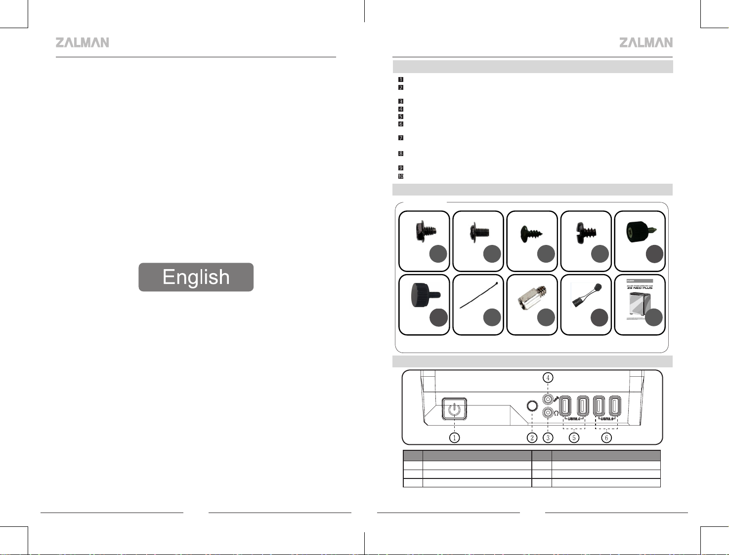
. Components
2
Components
. Top I/O Ports
3
8EA
Bolt A
Bolt B
Cable Tie
18EA
Bolt C
5EA
Stand off
# Part # Part
① Power Button ② Reset Button
③ Headphones ④ Mic
⑤ USB 2.0 ⑥ USB 3.0
2 3
6EA
3EA
Bolt D
12EA
Bolt E
1EA
Manual
Page 3
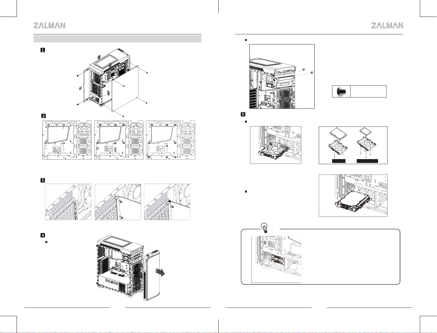
. Installation
4
Side Panel Removal
ODD Installation
BoltB
Motherboard Installation
M-ITX
There are 6 Stand-offs preinstalled. Please refer to the diagrams below for additional
Stand Off positions (based on motherboard type).
M-ATX ATX
VGA Card Installation
Unfasten the Hand Screw holding the PCI Cover and disassemble the cover.
Remove the PCI Slot Cover. Install the VGA Card and fasten with a fixing screw.
5.25” Drive Installation
Front Cover Removal
PULL
3.5”, 2.5” HDD Installation
Install the Drive on HDD tray
then remove the HDD Tray as
shown in the figure.
Install the Drive on HDD tray
Tip
3.5" HDD 2.5" SSD/HDD
Install the tray on the drive.
※ When transporting an assembled system,
Please secure the HDD whte Bolt as shown
above
4 5
Page 4
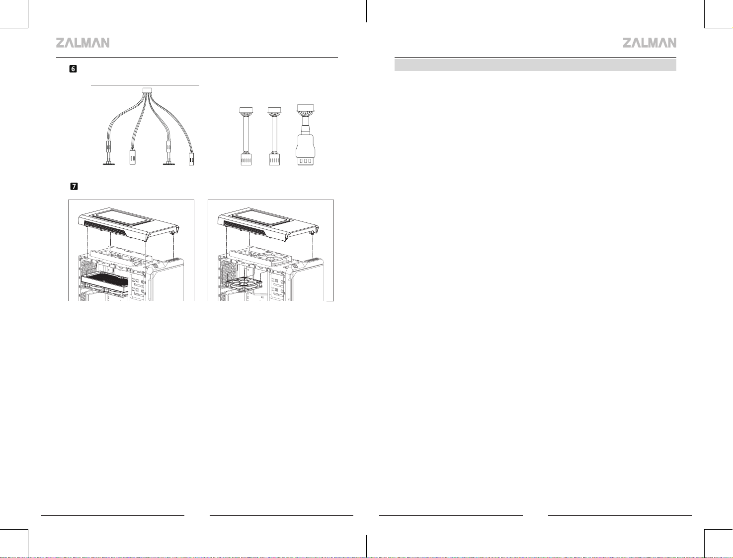
Cable Connection
Power Button
Power LED Reset Power HDD LED HD Audio USB 2.0 USB 3.0
How to Install the Cooler
As shown in the picture, install the cooler on the top of the case using bolts
I/O Port
. Warranty Information
5
Zalman Tech products come with the following limited warranties:
■
1 Year Warranty
CPU coolers (All CNPS series, Reserator 3 Max series, LQ3xx series), computer
cases, keyboards, mice, laptop coolers, case fans, hardware enclosures
(including VE series), audio devices, and all other accessories not specified below.
■
3 Year Warranty
HQ series AIO CPU coolers
■
7 Year Warranty
EBT series Power Supply Units
Zalman USA has the right to change availability of limited warranty at its
own discretion and any changes will not be retroactive.
■
The limited warranty does not cover…
1. Non-Zalman brand products and accessories.
2. Problems resulted from external causes such as accident, abuse, misuse,
and/or problems with electrical power.
3. Any service not authorized by Zalman USA.
4. Usage that is not in accordance with product instructions.
5. Failure to follow the product instructions and/or failure to perform preventive
maintenance.
6. Problems caused by using accessories, parts, and/or components not supplied
by Zalman.
7. Products with missing, altered Service Tags and/or serial numbers.
■
For United States and Canada
Technical support and warranty related inquiries: support.usa@zalmanusa.com
Toll free customer service: 1-888-925-6266
■
For all other regions
Send e-mail to techsupport@zalman.co.kr
For detailed warranty information, please visit www.zalman.com.
6 7
Page 5

. 주의사항
2EA
2EA
Bolt F
4EA
1EA
Speacker
1
설치 전 설명서를 숙독하십시오.
설치 전 제품과 구성품을 반드시 확인 후 이상이 있을 경우 구입처에 교환/환불 조치
받으십시오.
제품 설치 시 사고 예방을 위해 장갑을 착용하고 취급하십시오.
시스템 장착 시 치명적 손상이 발생할 수 있으므로 무리한 힘을 가하지 마십시오.
케이블을 잘못 연결하면 합선으로 인한 화재 우려가 있어 필히 설명서를 참고하여 연결하십시오.
시스템 사용시 제품의 통풍구가 막히지 않도록 주의 하십시오.
직사광선, 물, 습기, 기름, 먼지가 많은 곳을 피하고 공기가 잘 통하는 곳에서 보관/사용 하십시오.
화학약품 등으로 제품의 표면을 닦지 마십시오. (알코올 또는 아세톤 등 유기용제)
동작 중에는 인체나 제품에 해를 끼칠 수 있으므로 손이나 물체를 넣지 마십시오.
어린이의 손이 닿지 않는 곳에서 보관/사용하십시오.
정해진 용도 외의 사용 및 소비자 부주의로 발생한 문제는 당사에서 책임지지 않습니다.
제품의 외관 디자인 및 규격은 품질 향상을 위해 소비자에게 예고 없이 변경될 수 있습니다.
. 구성품
2
공용구성품
8EA
Bolt A
Bolt B
Cable Tie
18EA
Bolt C
5EA
Stand off
. 상면 I/O 포트
3
# 명칭 # 명칭
① 전원 버튼 ② 리셋버튼
③ 헤드폰 ④ 마이크
⑤ USB 2.0 ⑥ USB 3.0
8 9
6EA
3EA
Bolt D
12EA
Bolt E
A1E
Manual
Page 6

. 설치방법
4
사이드 커버 분리
마더보드 설치
ODD 설치
BoltB
3.5” & 2.5” HDD 설치
HDD 트레이에 드라이브 설치
기본 6개의 Stand-Off가 장착되어 있으며, 메인보드 장착 볼트 위치를 참조하여 마더보드 타입에 따
M-ITX
라 Stand-Off를 추가로 끼우고 마더보드를 케이스에 장착합니다.
M-ATX ATX
그래픽 카드 설치
PCI 커버를 고정하는 볼트를 풀고 커버를 분리한 후 PCI 커버를 제거합니다.
그래픽 카드를 설치하고 고정나사로 고정합니다.
5.25" 드라이브 설치
전면 커버 제거
PULL
10 11
HDD Tray를 그림과 같이 분리합니다. 트레이에 드라이브를 장착합니다.
3.5" HDD 2.5" SSD/HDD
HDD 트레이에 HDD 장착
Tip
※ 조립후시스템을 이동할 때는 해당위치에
나사로 HDD를 고정해 주시기바랍니다
케이블 연결
전원 버튼
Power LED Reset Power HDD LED HD Audio USB 2.0 USB 3.0
I/O Port
Page 7

쿨러, 팬 장착방법
그림과 같이 케이스 상단 장착 홀에 맞추어 볼트를 이용하여 장착 할 수 있습니다.
. 품질보증 및 A/S 안내
5
1. 품질 보증기간 : 제품 구입일로부터 1년 (단, 구입영수증이 있을 때)
2. 무상 A/S : 품질 보증기간 내에 제품 자체 성능상의 하자 및 불량 발생시
3. 유상 A/S : 품질 보증기간 이후에 제품 사용상의 문제 발생시. 단, 아래와 같은 사항에 대해서는
품질 보증기간 이내라도 무상 A/S 처리가 되지 않으며 소비자 부담으로 처리됩니다.
☞ 본 사용 설명서에 명시된 설치 전 주의사항 및 유의사항을 지키지 않은 경우
☞ 사용자의 고의나 과실 및 부주의로 인하여 변형, 파손/파괴된 경우
☞ 사용자의 임의 개조에 의한 변형 및 고장이 발생된 경우
☞ 품질 보증 스티커가 제거 또는 회손 되었을 경우
☞ 천재 지변으로 인해 고장이 발생된 경우
4. A/S
1) 운영시간 : 평일- 09:00~18:00 (공휴일,토.일요일 휴무)
2) 접수 방법
① 방문 접수 : 직접 방문할 경우 사전 연락 후 방문해 주시기 바랍니다.
② 택배 접수 : 택배(우편)를 이용하실 경우 성함, 주소, 연락처 및 불량 증상을 적은 메모지를
넣어서 보내주십시오.
※ A/S 의뢰 시 제품 박스가 필요하오니 보관하여 주십시오.
3) 접수처
◆ 고객지원센터 - ☏ 1588-3936
※ A/S 의뢰 시 제품은 A/S접수처로 보내시는 것을 원칙으로 합니다.
5. 제품 운송비용
1) 무상 A/S의 경우 : 무상 기간 내의 택배 운임비는 1회(선불) 고객 부담을 원칙으로 합니다.
2) 유상 A/S 및 보증기간 이후 : 왕복 비용 모두 고객 부담입니다.
12 13
Page 8

. Précautions
2EA
2EA
Bolt F
4EA
1EA
Speacker
1
Assurez-vous d'être bien informé du manuel du produit avant son installation.
Assurez-vous de vérifier l'état des composants et des produits, et s'il vous plaî consulter
votre revendeur quand il y a une erreur.
Assurez-vous de porter des gants pour éviter les blessures ou les accidents lors de la
manipulation de ce produit.
il y a un risque d'incendie dû à un court-circuit si vous les connectez incorrectement.
Veillez à ne pas bloquer les aérations à l'avant et à l'arrière du produit.
Installez le produit dans des endroits aérés, plats, et exempt de vibrations sans lumière
solaire directe, chaleur générée par le chauffage, éclaboussures d'eau (pluie),ou
beaucoup d'humidité et d'huile.
Ne pas nettoyer le produit avec des produits chimiques (produits chimiques, cirages
industrielles, alcool, dissolvant, lubrifiant, détergent etc.)
Ne pas mettre la main ou des objets dans le produit actif. Cela peut nuire au corps
humain et au produit.
Nous ne prenons aucune responsabilité pour les problèmes qui se produisent en
raison d'une utilisation autre que l'usage prévu
La conception ou les spécifications sont sujettes à modification sans préavis aux
clients afin d'améliorer la qualité du produit.
. Precauciones
1
Antes de instalar, leer rápidamente las insturcciones del producto.
Antes de instalar, verificar el estado del productos y los componentes y en caso de quehaya anomalías
consulte con el departamento de compras.
Para prevención de accidentes y heridas durante el manejo de este producto, usar guantes de
seguridad
Al conectar los cables, conecte los cables después de verficar el manual. En caso demal coneccion hay
peligro de fuego por corto circuito.
Precaucion en que el ventilador de la parte frontera y trasera del producto no este obstruido.
Evitar lugares que hay calor como lugares con rayo de sol directo o alrededor de calefacciones, lugares
que salpica agua (lluvia), lugares con mucho aceite o humedad e instalar en lugares que conduzca
mucho aire, plano y que no haya vibraciones.
No limpiar la superficie del producto con medicamentos químicos. (Medicamentos químicos, barniz
industrial, cera, benceno,alcohol, diluyente, medicamento para lubricante etc.)
No introducir las manos u objetos en los productos en movimiento. Puede causardanos al producto o
al cuerpo.
La compañía no será responsable sobre los problemas ocurridos por el usoademás del uso
determinado
El diseño exterior y el modelo del producto puede ser cambiado sin aviso previo al consumidor para
el mejoramiento de calidad del producto..
. Precauções
1
Verifique as instruções antes da instalação
Verifique o estado do produto e seus componentes antes da instalação caso exista algum defeito,
entre em contato com o vendedor para solicitar substituição / reembolso
Use as luvas quando instalar este produto para evitar acidentes
Não utilize força excessiva sobre o produto, pois isso pode causar o dano fisico
As conexões de cabo de forma incorreta podem provocar curto-circuito com riscos de incêndio,
consulte o manual antes da conexão
Não bloqueie a entrada de ventilação da frente ou a saída de ar traseira
Mantenha este produto longe da luz direta do sol, água, umidade, óleo e poeira e coloque-o em área
bem ventilada
Não limpe a superfície do produto com produtos químicos (solventes orgânicos, tais como álcool ou
acentona)
Não insira objetos ou as mãos no produto em funcionamento para evitar o dano ao produto e
prevenir lesões
Mantenha este produto longe do alcance de crianças
Zalman Tech S.A.R.L. não é responsável por quaisquer problemas que possam ocorrem devido ao
uso inadequado
O desenho e as especificações do produto podem estar sujeitos a alterações para melhoria da
qualidade e desempenho sem aviso prévio ao consumidor
. Composants, Precauciones, Precauções
2
Composants / Precauciones / Precauções
8EA
Bolt A
. Top I/O Ports, Puerto de I/O en superficie, Porta I/O de superfície
3
Bolt B
Cable Tie
18EA
5EA
Bolt C
Stand off
6EA
3EA
12EA
Bolt D
# Part Name # Part Name
①
③ Casque / Audífonos / Fone de ouvido ④ Mic
⑤ USB 2.0 ⑥ USB 3.0
Bouton d'alimentation
/ Botón de Potencia
/Botão de alimentação
②
Bouton de réinitialisation
/ Botón de Reinicio
/Botão de reset
Bolt E
A1E
Manual
14 15
Page 9

. Installation
4
Side Panel Removal / Retrait du panneau latéral / Remoção da tampa lateral
Motherboard Installation / Installation de la carte mère / Instalação de placa-mãe
M-ITX
There are 6 Stand Offs preinstalled. Please refer to the diagrams below for additional
Stand Off positions (based on motherboard type).
Il ya 6 Offs de stands préinstallés. S'il vous plaît se référer aux schémas ci-dessous pour
Stand Off postes supplémentaires (selon le type de carte mère).
Há seis isoladores impasse pré-instalados. Consulte a figura abaixo para montar um isolador
impasse adicional e instalar a placa-mãe para o caso de acordo com o tipo de placa-mãe
M-ATX ATX
Assemblage de la carte graphique / Ensamblaje de tarjeta grafica
/ Instalação do cartão VGA
Installation des lecteurs de 5.25” / Instalación de unidades de 5.25” / Instalação da
unidade de 5,25 "
Séparation de couvercle avant / Remover tapa frontal / Remoção da tampa frontal
PULL
Installation de l’ODD / Instalar ODD / Instalação de ODD
BoltB
Montage de HDD de 3.5”, 2.5” / Instalar bandeja 3.5”,2.5” / Instalar bandeja
3.5”,2.5”
Installer le lecteur sur le plateau de disque dur / Instale la unidad en la bandeja de
la unidad de disco duro / Instalação do HD na bandeja do módulo
Desserrer la vis à la main qui fixe le couvercle de PCI et séparer le couvercle. Retirer le couvercle du
logement PCI. Installer la carte graphique et la fixer avec vis de fixation.
Separar el cubierto desarmando el tornillo de mano que fija el cubierto PCI. Remover el cubierto de la
ranura PCI. Instalar la tarjeta grafica y fijar con tornillo.
o parafuso de mão que fixa a tampa de PCI e desmonte a tampa Retire a tampa do PCI Instale o
cartão VGA e aperte com o parafuso de ajuste
16 17
retirer le plateau de disque dur
comme illustré sur la figure.
Retire la bandeja
Remova a bandeja
3.5" HDD 2.5" SSD/HDD
Installation du disque sur le plateau
Equipar disco de bandeja
Instale o HD na bandeja conforme gura.
Page 10

Installation de HDD Tray /Instalar HDD
Tray / Instalação do módulo
Tip
※ Lorsque vous déplacez le système
à l'ensemble à sa place Vis A pour écuriser
le disque dur s'il vous plaît.
※ Al mover el sistema a la asamblea en
su lugar Tornillos A para asegurar la
unidad de disco duro, por favor.
※ Quando transportar um sistema
montado, por favor garantir o HDD com
Parafuso A como mostrado cima.
onnexion des câbles / Cable Connection / cabo de Conexão
Power Button
I/O Port
Montage du refroidisseur / Instalación del enfriador / Instalando o refrigerador
Fixer le refroidisseur avec les boulons pour s'adapter aux trous de montage sur le dessus du boîtier
comme indiqué dans la gure.
Encaje el enfriador en el orificio de instalación de la parte superior de la caja y luego instálelo con el
tornillo como se muestra en la figura
Furos de montagem, como mostrado na figura em cima do caso, utilizando os parafusos de
montagem para se adequar.
Power LED Reset Power HDD LED HD Audio USB 2.0 USB 3.0
18 19
Page 11

 Loading...