


※ For other language versions please visit our website.

English
English Edition
www.zalman.co.kr www.zalmanusa.com
◈ Please read before installation.
◈ Visit our website and watch the TNN500AF installation video first to make
your installation easier.

English
TNN 500AF
▣ Welcome
Congratulations on your purchase of ZALMAN Tech’s TNN 500AF.
With TNN500AF, you are now in the world of silent computing. TNN
500AF is the ultimate answer to every computer user’s dream of
creating a silent computing environment with total system stability.
▣ Contents
1. Safety Notices
2. Features
3. Patents
4. Components
5. Optional Components
6. Specifications
7. Operational Notes
8. Installation Guide
9. Trademarks and Copyright Notice
3
4
11
12
15
15
19
20
47

3
English
1. Safety Notices
TNN 500AF
1) Keep this unit away from heat sources and direct sunlight.
2) This unit should be placed on a flat, level, and solid surface.
3) Always shut down the operating system and switch the AC OFF before disassembling.
4) Keep this unit in an upright position when the AC power is ON.
5) Do not place or spill liquids on this unit.
6) Avoid inserting any objects into the system while it is ON.
7) Lower the caster stops to immobilize the unit before using the system.
8) If this unit is to be transported a long distance, place it in the original packing box or a custom
made hard case.
9) Do not drop or expose this unit to shock while it is in transit.
10) Store and use out of the reach of children.
11) Check the condition of the product and its components before installation.
If there is a problem with the product and/or its components, please contact the Retailer
immediately.
◈
Disclaimer
Zalman Tech Co., Ltd. Is not responsible for any damages due to external causes, including
but not limited to, improper use, problems with electrical power, accident, neglect, alteration,
repair, improper installation, or improper testing.
1
Safety Notices
TNN 500AF is the world’s first truly noiseless high-end computer case, developed with heatpipe
technology, HSC(Heat Source Contact) power technology, High Capacity Extrusion technique,
and FMS (Flexible Mounting Structure) design technology by ZALMAN Tech Co., Ltd. The
TNN 500AF package contains a high performance aluminum computer case with an absolutely
noiseless cooling solution for the CPU, VGA Card, Power Supply, and Northbridge free of fans,
making it ideal for storage servers, workstations, high-end home systems, and sound studio
computer systems.
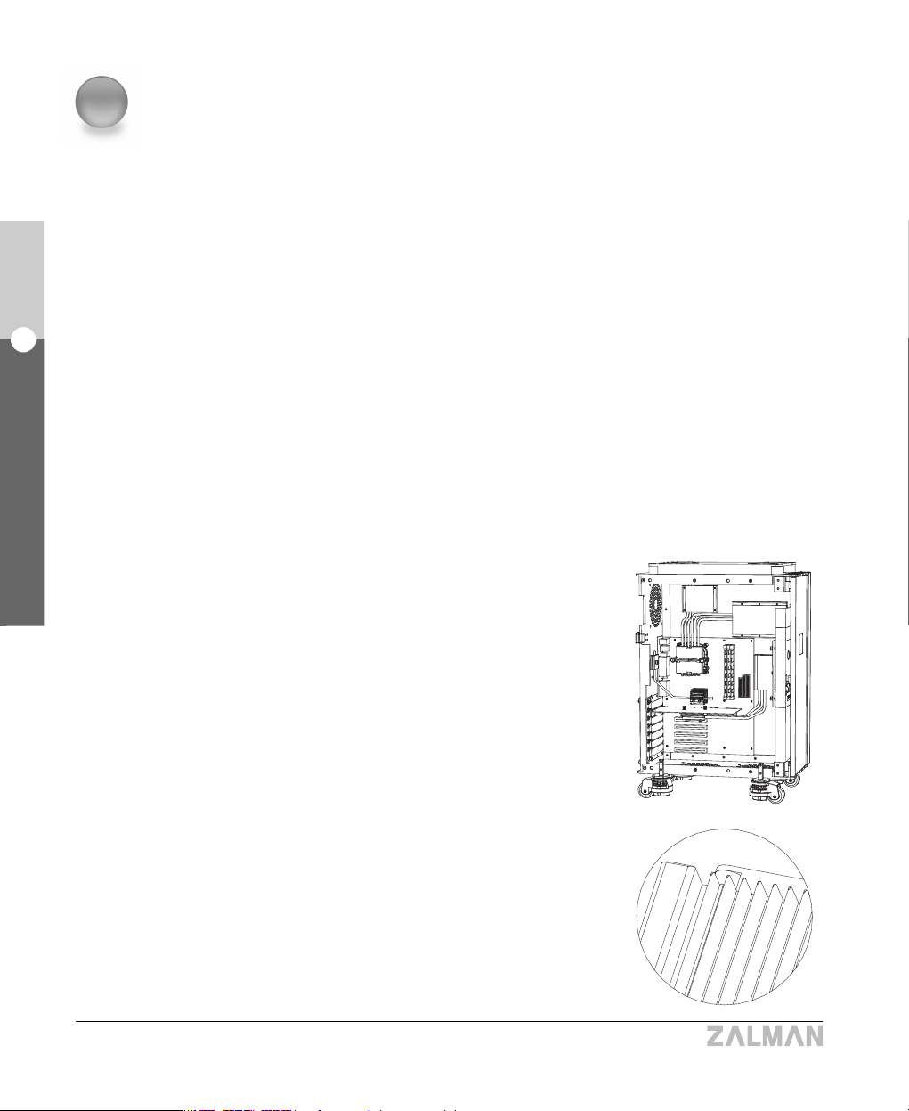
1) Complete Silence
The cooling system does not generate any noise because it does not utilize any fans. Even
the HDD noise is blocked out by the sturdy aluminum plates 5 to 7mm thick, achieving
completely silent computing.
2) Stability
①
No Fans in the System
The majority of heat generated inside the system is
transferred through heatpipes to the heatsink plates
where it is dissipated via natural convection, reducing
inflow of dust dramatically. Consequently, this
prevents system crashes caused by dust buildup and
fan failures (fans last around 20,000 to 50,000 hours).
② High-Capacity Aluminum Heatsink Plates for
Natural Convection
Two large aluminum heatsink plates cool heat
generating components, such as the CPU and VGA
Chipset, through natural convection. Without any
moving parts, the TNN 500AF is virtually free of the
need for mechanical maintenance, and it is 100%
recyclable, making it environmentally friendly.
2
Features
4
English
2. Features
TNN 500AF
English
2. Features
TNN 500AF
5
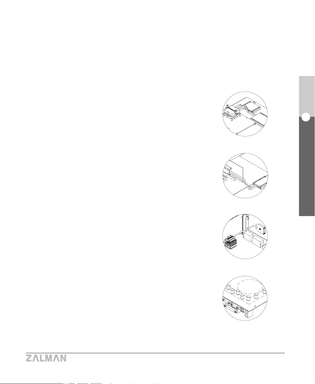
③
Heat Transfer via Heatpipes
Virtually ever-lasting heatpipes transfer heat away
from the CPU, VGA chipset, and Northbridge chipset
preventing system crashes due to over heating.
- CPU Heatpipes
Heat from the CPU is transferred to the heatsink plate
through 6 heatpipes each 6 millimeters in diameter.
The six heatpipes can transfer up to 150W of heat
from the CPU - sufficient for the hottest CPUs on the
market. The CPU Block Base is made of pure copper
to ensure the highest cooling performance.
- VGA Card Heatpipes
Heat from the VGA Card is transferred to the heatsink
plate through 3 heatpipes each 6 millimeters in
diameter. The three heatpipes can transfer up to 75W
of heat from the VGA chipset - sufficient for the hottest
VGA cards on the market.
- Northbridge Heatpipe
Heat from the Northbridge chipset is transferred to the
heatsink plate through a single heatpipe, 5 millimeters
in diameter. This heatpipe can transfer up to 20W of
heat.
③
Heat Transfer via Rear-mount Thermal Blocks
When the Rear-mount Thermal Blocks are installed on
the back-side of the motherboard in line with the
position of the FETs (Field Effect Transistor) and the
Northbridge chipset, each can lower the FET
temperature by 10 to 30
°C
and the Northbridge chipset
by 5 to 10
°C
.
CPU Heatpipes
VGA Card Heatpipes
Northbridge Heatpipe
Rear-mount Thermal Blocks
6
English
2. Features
TNN 500AF
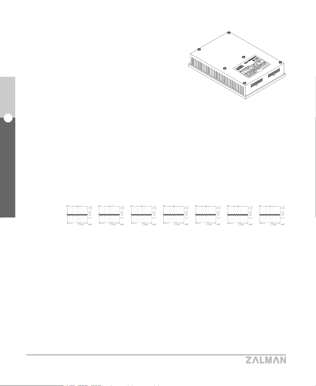
⑤
High-Efficiency, Fanless Power Supply
The power supply uses high-efficiency FET
components and Heat Source Contact (HSC)
technology, eliminating the need for a fan, and
has a 10% higher power conversion efficiency
(80%) rating than conventional power supplies.
Heat from the power supply is transferred
directly to the high-capacity heatsink plates,
where it is dissipated by natural convection,
making the power supply free of noise and
vibration.
- High-capacity active PFC inductors, separate switching transformers for each power rail
(+12V, +5V, +3.3V), and 2-FET forward converter design all work to create a superior
level of stable power quality.
- Conventional power supplies tend to have lower output voltage due to line-dropping
phenomenon. The TNN Power Supply extends the output voltage sensors up to the
motherboard connection for +3.3V, +5V, and +12V rails to prevent this, enhancing
output voltage accuracy and assuring system stability.
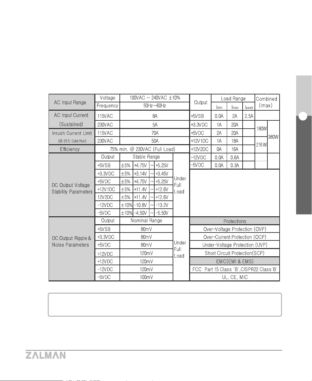
※
Data above were measured according to INTEL ATX v2.03/ATX12V power supply specs.
Measurement specifications : For each DC output, a bypass made up of one 0.1μF
ceramic capacitor and one 10μF electrolytic capacitor is connected and measured with
an oscilloscope (input impedance 1MΩ) at a frequency bandwidth of 20MHz. The
waveforms may differ under different measurement conditions.
■ Ripple and noise waveforms at DC output
a)+5VDC
(21.4mVp-p)
b)+3.3VDC
(42.2mVp-p)
c)+12V1DC
(80.8mVp-p)
d)+12V2DC
(88.4mVp-p)
e)-12VDC
(98.4mVp-p)
f)-5VDC
(56mVp-p)
g)+5VsdDC
(31.8mVp-p)
3) Electricity Conservation
Since TNN 500AF is equipped with a high-efficiency power supply and does not use any
fans, it utilizes 10 to 15% less power compared to a conventional computer system under the
same configuration.
7
English
2. Features
TNN 500AF
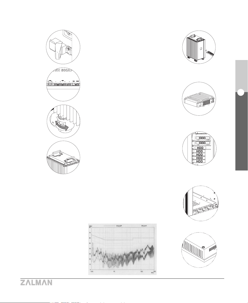
4) Ease of Use
① A latch is installed to prevent component
theft.
② The Remote Control enables the user to
conveniently experience multimedia
content and control the PC.
③ Various I/O ports are provided (Audio,
USB, IEEE-1394, 1394B)
④ Heatpipe HDD Cooler dissipates heat
from the hard disk and reduces vibration
transferred to the case.
⑤ Four casters (wheels) withstand up to four
metric tons of weight in total, and have
skid prevention / height adjustment
features built in.
⑥ The case is structured to easily house up
to two ODDs and five HDDs.
⑦ Retractable handles are attached for
short-range transportation.
5) Shielding from EMI (Electro-Magnetic
Interference)
The sturdy, thick (5 to 7mm) aluminum case and the EMI Interception
Block effectively contain EMI. Even the power supply housing is designed
with EMI shielding.
EMI Interception Block
EMI Interception Design
EMI Measurement Data Graphs
❶❷
❸
❹
❺
❼
❻
8
English
2. Features
TNN 500AF
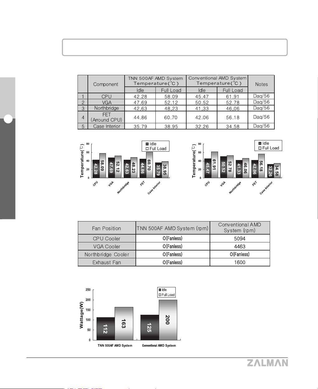
※
Test Results
▶ AMD AMD64 Athlon64 System
① Thermal Test (Room Temperature : 25
℃)
TNN 500AF AMD System Conventional AMD System
※ Fan rpm at Full Load
② Power Consumption Test
9
English
2. Features
TNN 500AF
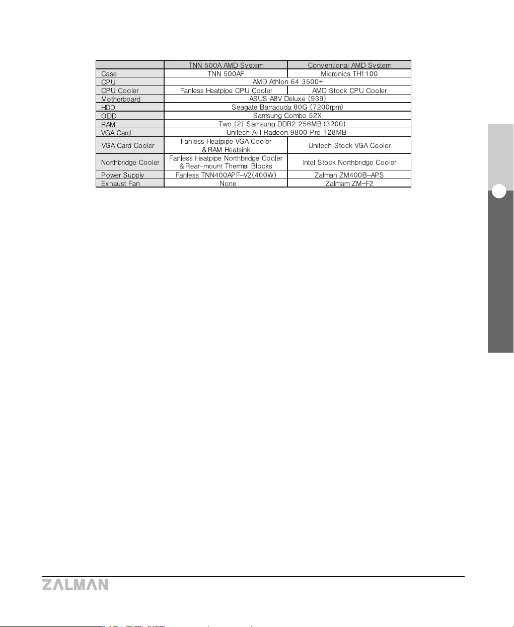
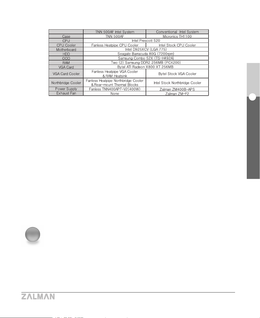
③
Configuration of Systems for Testing
④ Testing Equipment and Programs
▣▣
CPU Loading Program
CPU Burm (47, High)
▣▣
Measurement Instrument
Personal Daq/56 (Iotech, Inc.) KIKUSUI PCR 1000L
▣▣
Temperature Measurement Program
DaqView (Iotech, Inc.)
10
English
2. Features
TNN 500AF
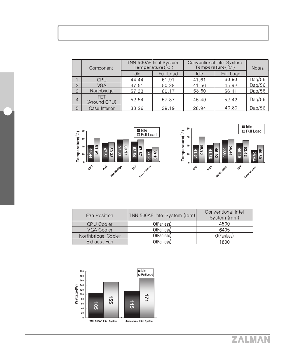
※ Fan rpm at Full Load
▶ Intel P4 Prescott System
① Thermal Test (Room Temperature : 25
℃)
② Power Consumption Test
TNN 500AF Intel System Conventional Intel System
11
English
3. Patents
TNN 500AF
◈ Korean Patent Application #04-82817
◈ Korean Patent Application #03-30358
◈ Korean Design Application #03-19970
◈ International patent applications pending in the EU, USA, Japan and 30+ other countries
3
Patents
③ Configuration of Systems for Testing
④ Testing Equipment and Programs
▣▣
CPU Loading Program
Maximum Power Program for the Prescott Processor Rev. 1.2
▣▣
Measurement Instrument
Personal Daq/56 (Iotech, Inc.) KIKUSUI PCR 1000L
▣▣
Temperature Measurement Program
DaqView (Iotech, Inc.)
※ Caution
1) If the CPU has a higher Thermal Design Power (TDP) rating than an Intel Prescott or
an AMD Athlon64 3500+, the Heatpipe Northbridge Cooler and a Rear-mount Thermal
Blocks (ZM-RTB1) MUST be installed to cool the Northbridge.
2) To use CPUs with a 100W or higher TDP rating, Rear-mount thermal Blocks Must be
installed (one for each FET) on the backside of the motherboard in-line with each FET.
4
Components
12
English
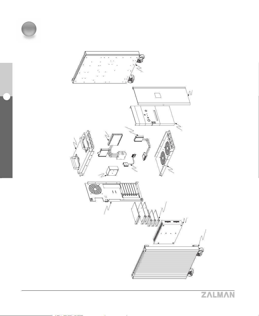
4. Components
TNN 500AF
Right Heatsink Plate
Front Door
Swithch & Front
Aux. Panel
Top Plate & Cover
CPU Cooler Parts
Power Inlet
Bottom Plate
ODD/FDD/HDD
Bracket
Fanless
Power Supply
Left Heatsink Plate
Rear Plate
Northbridge
Cooler Parts
VGA Cooler
Parts

13
English
4. Components
TNN 500AF
1) Heatpipe CPU Cooler Parts [One(1) Bag]
1) Components for Intel Pentium 4 (Socket 478)
2) Components for Intel Pentium 4 (Socket 775)
3) Components for AMD Amd64 (Socket 478)
One (1) Socket 478 CPU Clip
Four(4) PH M4X22 bolts
Two (2) Socket 478 Finger Bolts (M3X52)
Two (2) Socket 478 Clip Supports
One(1) Socket 775 Clip Support
One(1) Socket 754 Back Plate
Two Socket 754 Finger Bolts (#6-32X40)
Two (2) Socket 754 AMD Nipples
Two (2) Socket 775 Finger Bolts (M3X49)
Four (4) PH M3X22 Bolts
2) Heatpipe VGA Cooler Parts [One(1) Bag]
VGA Block A/B & Cover [one(1) Each]
Four (4) VGA Finger Bolts A (M2.5)
Eight (8) Ram Heatsinks
Four (4) VGA Springs
Four (4) VGA Finger Bolts B (M3)
Paper Washers
3) Heatpipe Northbridge Cooler Parts [One(1) Bag]
Block Base
Block Cover
Thermal Pad Two (2) Common Finger Bolts
4) Heatpipe HDD Cooler
One (1) ZM-2HC2 Set
5) Rear-mount Thermal Blocks
One(1) ZM-RTB1 Set (8 Blocks)
6) HDD Set [One(1) Bag]
Five (5) Ground Wires Twenty Four (24) FH #6-32X7 Bolts

14
English
4. Components
TNN 500AF
※
Interpreting the Bolt Abbreviations
PH M4X20 : PH(Pan Head) Type, Meter Screw, 4mm in Diameter, 20mm in Length
FH #6-32X8 : FH(Flat Head) Type, Screw #6, 32 Pitches per Inch, 8mm in Length
Pan Head Pan-Washer Head Flat Head Socket Head
7) ODD/FDD Bolts
[One(1) Bag]
Twelve (12) PH M3X10 Bolts
8) Motherboard Bolts
[One(1) Bag]
Ten (10) PWH M3X5 Bolts
9) Thermal Grease
2.5 ml
10) ATA 133 Cable
[One(1) Bag]
One (1) ATA 133 Cable
11) Power Cord [One(1) Bag]
One (1) Power Cord
12) Latch Key
[One(1) Bag]
Two (2) Latch Keys
14)
Motherboard Power Cable [One(1) Bag]
15)
TNN 500AF User’s Guide (1Copy)
One(1) TNN 500AF
User’s Guide
16) Spare Parts
[One(1) Bag]
Length
Length
Length Length
13) Remote Control Set
One(1) Remote Control
Two(2) AAA Batteries
One(1) Motherboard Power Cable
(24 pin -> 20pin)
One(1)
Installation CD
One(1) iMON & Multi-Median
User’s Guide

15
English
5. Optional Components
TNN 500AF
5
Optional Components
6
Specifications
1) Model : TNN 500AF
2) Dimensions : 400(L) x 286(W) x 597(H) mm
3) Weight : 26Kg
4) Compatible CPUs : All Intel Pentium 4 CPUs and AMD AMD64
CPUs Supported
※ NOTE : When the Thermal Design Power rating of the CPU is 100W or higher, a quiet 120mm
case fan MUST be installed and operated at 1000~1200rpm, and Rear-mount Thermal
Blocks (ZM-RTB1) must be installed on the backside of the motherboard. Refer to page 22.
1) CPUs that require a quiet case fan and Rear-mount Thermal Blocks(ZM-RTB1)
(As of Oct. 30, 2004)
(※ Before using one of the latest CPUs, check our website for usage guidelines and
information regarding compatibility.)
CPU
Intel Pentium 4
AMD AMD64
Prescott 3.2E GHz
Prescott 550 (3.2 GHz)
Athlon 64 FX 55 (2.6 GHz)
Socket
478
775
939
TDP
103W
115W
104W
Heatpipe HDD Cooler (ZM-2HC2)

16
English
6. Specifications
TNN 500AF
※ Notes
1. NVIDIA PCX Series VGA Cards are not supported. Replace with a Zalman-recommended
VGA card.
2. If the VGA card does not install normally due to physical incompatibility with the case, stop
installation and replace with a Zalman-recommended VGA card listed on the following website.
(www.zalman.co.kr/product/TNN500AF)
2) CPUs with Thermal Design Power ratings under 100W. (As of Oct. 30, 2004)
(
All CPUs that are slower than those mentioned above have Thermal Design Power ratings under 100W.
)
3. Refer to the following website for more information regarding CPU compatibility.
(www.zalman.co.kr/product/TNN500AF.html)
CPU
Intel Pentium 4
AMD AMD64
Northwood 3.4 GHz
Prescott 3.0E GHz
Prescott 540 (3.2 GHz)
Athlon 64 4000 + (2.4 GHz)
Athlon 64 FX 53 (2.4 GHz)
Opteron 150 (2.4 GHz)
Socket
478
478
775
775
939
940
TDP
89W
89W
84W
89W
89W
84W
5) Compatible VGA Cards
All AGP / PCI Express VGA cards that have heatsink mounting holes
(As of Oct. 30, 2004)
Manufacturer
ATI
nVidia
Matrox
Model
Up to X 800 XT
Up to geForce 6800
All Parhelia Series
Heatsink Mounting Hole
17
English
6. Specifications
TNN 500AF
List of compatible motherboards, HDDs, and ODDs for building a TNN 500AF system is
available at the following website (www.zalman.co.kr/product/TNN500AF.html).
6) Thermal Transfer Capacity
① CPU Heatpipe (ZMC-6HB) : 150W
② VGA Card Heatpipe (ZMV-3HA) : 75W
③ Northbridge Heatpipe (ZMN-1HB) : 20W
7) Power Supply Output Capacity : 400W
8) Power Supply Electrical Specifications (Model : TNN400APF - V2)

18
English
6. Specifications
TNN 500AF
9) Output Power Cable
Motherboard Power
(20-Pin)
Motherboard Power
(24-Pin)
Remote Control
Standby Power
VGA Card Auxiliary
Power
Motherboard
Auxiliary Power
HDD/ODD Power
FDD Power
VGA Card
Auxiliary Power
HDD/ODD Power
Serial ATA HDD
Power

19
English
7. Operational Notes
TNN 500AF
7
Operational Notes
1) Operating Environment
Recommended Room Temperature : 15~28
℃℃
Operation in comfortable room temperature is recommended.
2) Precautionary Notes on Booting
When booting the computer, it may automatically power down after an alarm sound is
generated to indicate that the rotation of the CPU fan is slow by a system monitoring
program. If this happens, connect the fan on the stock CPU Cooler to the 3-pin connector for
the CPU Cooler on your motherboard. Boot the system and set “CPU Fan Detected”to
“Disabled”in the BIOS settings. Turn the system off, remove the CPU Cooler fan, and
reboot.
NOTES)
1. Some motherboards do not boot if the rotation of the CPU fan is not detected. There
might not be a "CPU Fan Detected“ setting in the BIOS setup, but updating the BIOS could
solve this problem. For more information on updating the BIOS, please refer to your
motherboard manufacturer’s website.
2. When using an Intel motherboard, if you remove the motherboard from an existing
system and attach it to the TNN 500AF, the system’s Active Monitor may generate an
alarm sound with a warning that there is no CPU fan. Remove Active Monitor from
Add/Remove Programs applet in Control Panel and reinstall.
3) Compatible Components
A list of compatible components for building a TNN 500AF system is available at the following
website (www.zalman.co.kr/product/TNN500AF.html).
※ NOTE
Only use motherboards recommended by Zalman.[Certain motherboards have unusually
high power consumption and/or are not compatible with the Rear-mount Thermal Blocks
(ZM-RTB1). Refer to Page 22.]

8
Installation Guide
20
English8. Installation Guide
TNN 500AF
1) Opening and Disassembling the TNN500AF Case
① As shown in the diagram, lay the TNN500AF down on a flat surface and open the front door.
② Open the latch with the key.
③ Unscrew four bolts (PH M5x15-S) on the Left Heatsink Plate and open the plate as shown.
④ Remove the blocks and Heatpipes in an orderly fashion using a screwdriver and store them
in a safe place.
The Bushings and the bolts separated at the
time of the CPU Block’s removal are simply
for packaging purposes and are not used for
the actual assembly of the system.
Left Heatsink Plate
Front Door
Bolt (PH5x15-S)
Latch
CPU Block
Bolt
(PH M3x60)
Bushing
(34mm)
}
Packing
Parts
21
English
8. Installation Guide
TNN 500AF
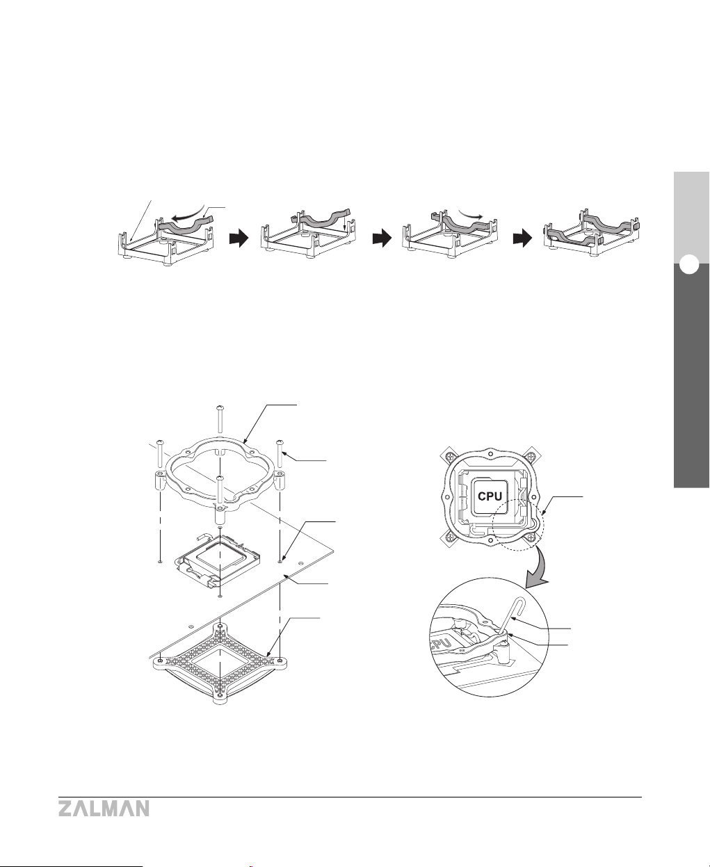
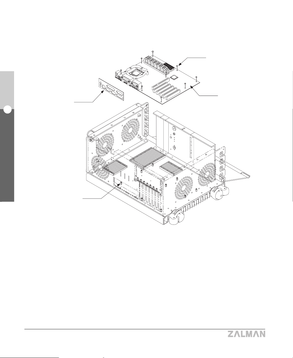
2) Installing the CPU Clip Support and Motherboard
① Choose the correct Clip Support & bolts for the CPU type being used.
▶ For Intel Pentium 4 Socket 478 Motherboards
Place two Socket 478 Clip Supports on the notches of the Retention Guide.
▶ For Intel Pentium 4 Socket 775 Motherboards
Align the Socket 775 Clip Support and the Socket 775 Back Plate with the mounting
holes on the motherboard and fasten with bolts (PH M3x22).
NOTE) The Lever Slot on the Clip Support should be properly oriented on the hinged side
of the Socket Lever when installing.
Retention Guide
Socket 478
Clip Supports
Socket 775
Clip Support
Bolt(PH M3x22)
Hole
M/B
Socket 775
Back Plate
Installation for Intel P4 Socket 478 Motherboards
Installation for Intel P4 Socket 775 Motherboards
Lever slot
Socket Lever
Lever slot

▶ For AMD AMD64 Motherboards
Insert the Socket 754 AMD Nipples into the holes on the Retention Frame and fasten
the Socket 754 Back Plate .
22
English
8. Installation Guide
TNN 500AF
Socket 754 AMD Nipple
Retention Frame
M/B
Socket 754 Back Plate
3) Installing the Rear-mount Thermal Blocks
Caution)
1) Motherboards with a Northbridge that has integrated video capability is not recommended.
If such Northbridge is used, the Rear-mount Thermal Blocks MUST be installed.
2) Zalman Tech does not recommend using a motherboard with a fan on the Northbridge
Cooler. If the fan is removed, the Rear-mount Thermal Blocks MUST be installed.
3) If the CPU has a higher Thermal Design Power (TDP) rating than an Intel Prescott or an
AMD Athlon64 3500+, the Heatpipe Northbridge Cooler and a Rear-mount Thermal Block
MUST be installed to cool the Northbridge.
4) To use CPUs with a 100W or higher TDP rating, Rear-mount Thermal Blocks MUST be
installed (one for each FET) on the backside of the motherboard in-line with each FET.
5) If interference occurs between components or any problems appear, visit Zalman’s
website for a list of recommended motherboards, and replace before installation.
(www.zalman.co.kr/product/TNN500AF.html)
6) The Rear-mount Thermal Blocks are proprietary components of Zalman’s TNN series cases.
Do not use with other cases!
Installation for AMD AMD64 Socket 754 Motherboard

23
English
8. Installation Guide
TNN 500AF
① Determine the points that correspond to the location of the FETs and Northbridge chipset on
the back side of the motherboard.
② Clean the surface of the point where the block will be attached.
③ Peel off the Film from the Thermal Pad on both ends of the block.
④ Firmly attach the blocks on the determined points.
NOTES : 1) To prevent short circuiting the motherboard, avoid soldered points, and any exposed
wiring or circuitry when installing the Rear-mount Thermal Blocks.
2) Thermal Pads lose adhesiveness after it has been used once. Try to attach it properly
on the first attempt.
3) Do not touch the Thermal Pad with your hands.
Film
Thermal Pad
Northbridge Chipset Area
CPU Area
Film
Rear-Mount
Thermal Block
FET Area
M/B
24
English
8. Installation Guide
TNN 500AF
⑤ Install the motherboard using the bolts (PWH M3x5).
NOTES
1) To prevent short-circuiting the motherboard, nipples that are not required for motherboard
installation must be removed first.
2) Fix the motherboard to the TNN using all of the motherboard’s mounting holes.
3) Be careful to not let the Rear-mount Thermal Blocks fall off from the back of the motherboard.
Bolt (PWH M3x5)
M/B
I/O Shield
M/B Nipple

25
English
8. Installation Guide
TNN 500AF
4) Installing the Heatpipe
Northbridge Cooler
NOTES
1) The Heatpipe Northbridge Cooler can be
installed only when the Northbridge is located in
the appropriate area as shown in the diagram.
2) If the Northbridge chipset is located in the
inappropriate area, it should be cooled with a
Rear-mount Thermal Blocks(Refer to page 22).
If the CPU’s Thermal Design Power rating is
lower than an AMD Opteron 3500+ or Intel
Prescott, it is not necessary to install a Rearmount Thermal Block for the Northbridge, for
the Heatpipe Northbridge Cooler is sufficient.
Appropriate
installation
area
inappropriate
installation
Area
① Check what type of Stock Northbridge Heatsink is on the motherboard and determine the
method of Northbridge Block installation.
※※
Notes on Installation of the Adhesive Type
1. The Thermal Tape must be adhered to the bottom of the Northbridge Block.
2. Remove the film from the Thermal Tape before adhering the Northbridge Block to the
Stock Northbridge Heatsink.
Northbridge
Block
Northbridge
Stock Heatsink
Thermal
Tape Film
Sliding Adhesive Type
26
English
8. Installation Guide
TNN 500AF
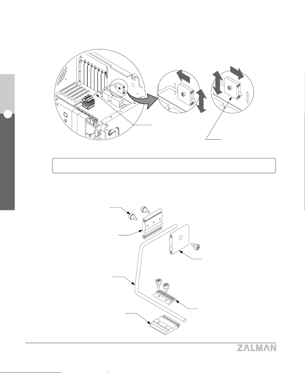
② Determine the installation point of the Northbridge Case Block and the Northbridge Heatpipe.
The Position of the Northbridge Case Block can be adjusted horizontally as well as vertically.
Northbridge
Heatpipe
Common Finger Bolt
Northbridge Case Block Base
Northbridge Heatpipe
Northbridge Block Base
Northbridge Case
Block
The position of the Northbridge Case Block can be adjusted horizontally as well as vertically.
③ Assemble and install the Northbridge Cooler as shown in the Diagram.
Northbridge Case Block Cover
Northbridge Block Cover

27
English
8. Installation Guide
TNN 500AF
5) Installing the Heatpipe CPU Cooler
① Refer to the diagram below to check the appropriate layout of the CPU Heatpipes for each
general location of the CPU.
NOTES
1)If the CPU Heatpipes interfere with certain
components, turn the Heatpipes upside down or
adjust the CPU Case Block Base A vertically and
try installing again.
2) If the CPU is located beyond the appropriate area
and the Cooler is deemed uninstallable, stop and
replace the motherboard with a Zalman-recommended
model (www.zalman.co.kr/product/TNN500AF.html)
Appropriate
Area
CPU Case Block Base A
CPU Heatpipes
28
English
8. Installation Guide
TNN 500AF
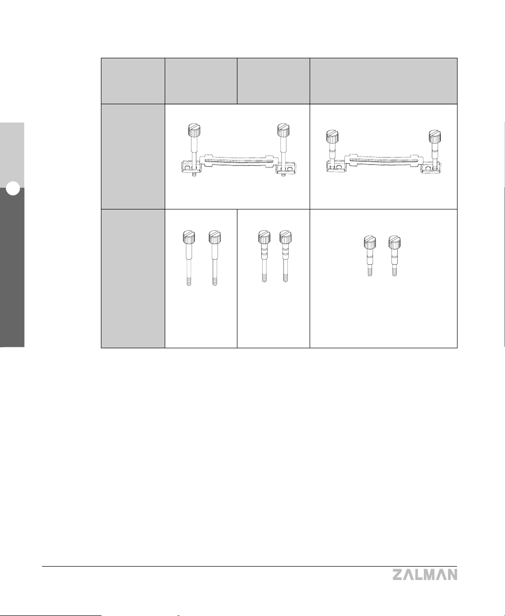
② Determine the appropriate CPU Finger Bolts & clip holes.
NOTES
1) Apply a generous quantity of thermal grease (1mm or 0.04 inches in height) on the
CPU core, and install the CPU Block Base (gold colored).
2) Apply thermal grease on the grooves of the CPU Block Base and the CPU Case Block
Base where the CPU Heatpipes come in contact.
3) The CPU Case Block Base already has thermal grease coated underneath, so it
should not be taken off under normal circumstances.
4) Use a coin or a screwdriver to firmly tighten the CPU Finger Bolts.
Intel
Socket 478
TYPE
Appropriate
Installation
Holes
Finger Bolts
To Use
Intel
Socket 775
AMD
Socket 775
(Inner Holes) (Outer Holes)
Socket 478
Finger Bolts
(M3x52)
Socket 775
Finger Bolts
(M3x49)
Socket 754
Finger Bolts
(#6-32x40)

29
English
8. Installation Guide
TNN 500AF
CPU Finger Bolt
Clip
Bolt(PH M4x20)
CPU Block Cover
CPU Heatpipe
CPU Block Base
Thermal Grease
Bolt(PH M3x15)
CPU Case Block Cover
CPU Case Block Base
Thermal Grease
③ Install the Heatpipe CPU Cooler as shown in the diagram.

30
English
8. Installation Guide
TNN 500AF
6) Installing the Heatpipe VGA Cooler
NOTE) If the VGA card interferes with certain components of the case, stop and refer to the
following website (www.zalman.co.kr/product/TNN500AF.html), and replace the VGA
card with one that is recommended.
As you install the VGA card, move the VGA Case Block Base vertically as needed to
accommodate the VGA card.
VGA Case
Block Base
① Remove the Stock VGA Cooler on the VGA card and clean off the exposed contact surface
completely.
NOTE) Be extremely careful when taking off the Stock VGA Cooler. Zalman is not responsible
for any damages Due to user negligence during the Cooler’s removal.
TYPE VGA Block Base A VGA Block Base B
Block
ATI
Nvidia
Matrox
ATI Radeon Series
GeForce4 Ti Series
GeForce3 MX Series
-
FX 5900 Series
GeForce 6800 Series
Parhelia

31
English
8. Installation Guide
TNN 500AF
② Peel off the Film from the Thermal Tape on the bottom of the RAM Heatsinks.
③ Stick the RAM Heatsinks onto the VGA RAM chips. Press the RAM Heatsinks firmly with
your finger for proper adhesion.
NOTE : 1) The bending strength of the Thermal Tapes reaches 90% after 24 hours of curing.
Do not put excessive force on the RAM heatsinks during this period.
2) Avoid getting grease or any kind of stain on the surface of the Thermal Tape.
The Thermal Tape may not stick. Clean the surface of the RAM with acetone or
alcohol before attaching.
1) If there are more than 8 VGA RAM chips on your VGA card, purchase additional RAM
Heatsinks (ZM-RHS1).
2) Thermal Tape loses adhesiveness after it has been used once. Thermal Tape cannot be
reused after it has been detached from a surface. If you need more, purchase it separately.
Thermal Tape
Thermal Tape Film
RAM Heatsink
VGA RAM
VGA Chipset

32
English
8. Installation Guide
TNN 500AF
NOTE) The VGA Case Block Base already has thermal grease coated underneath, and
should not be taken off under normal circumstances.
④ Apply a thin layer of thermal grease on the VGA chipset.
NOTE) Most VGA chipsets on the VGA card have a concave curvature towards the middle and
need more thermal grease at the center.
⑤ Make sure the VGA Block Base is level and firmly installed onto the VGA chipset using the
Paper Washers, the VGA springs, and the VGA Finger Bolts A(M2.5).
⑥ Apply thermal grease evenly onto the grooves on the VGA Case Block Base that come in
contact with the VGA Heatpipes, and install the VGA card on the motherboard.
VGA Finger Bolt A (M2.5)
VGA Spring
Paper Washer
VGA Chipset
Thermal Grease
Thermal Grease
VGA Block Base
VGA Block Base
VGA Case Block Base
M/B
33
English
8. Installation Guide
TNN 500AF
NOTES
1) There are many types of VGA cards and the VGA Heatpipes may not fit the grooves on the VGA
Case Block very well. In this case, the user needs to modify the VGA Heatpipes to fit the grooves.
2) If the VGA Heatpipes must bend below the datum line, the VGA Heatpipes will not function
properly and the VGA chipset may get damaged. Check if this is the case before proceeding.
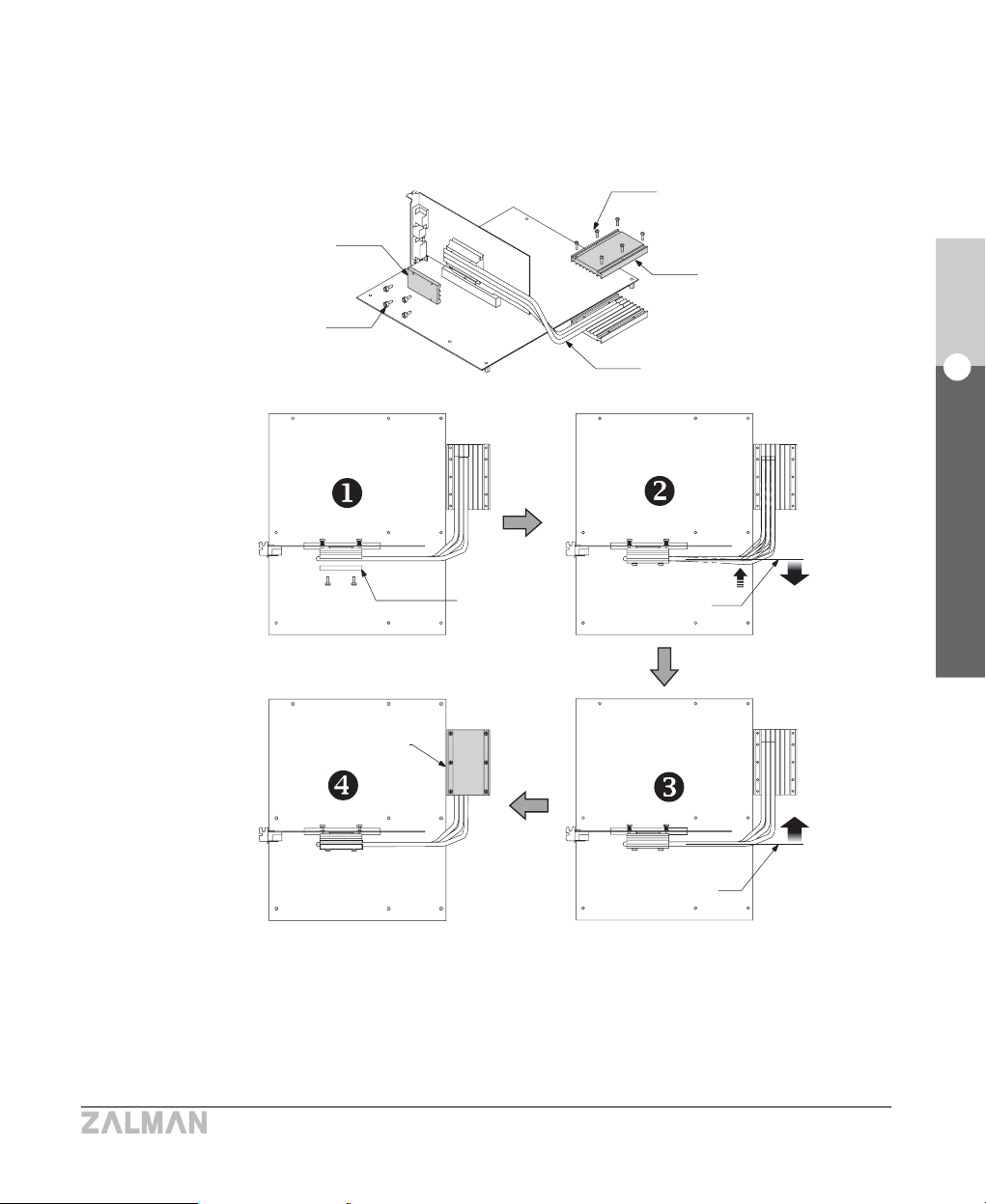
⑦ Install the VGA Heatpipes in sequence and fix the Block Cover over them using the VGA
Finger Bolts B(M3). Then, fix the VGA Case Block Cover using bolts (PH M3x15).
Bolt(PH M3x15)
VGA Case Block Cover
VGA Heatpipe
VGA Block Cover
VGA Finger
Bolt B (M3)
VGA Block
Cover
VGA Case
block Cover
Datum Line
Datum Line
NO
OK
34
English
8. Installation Guide
TNN 500AF
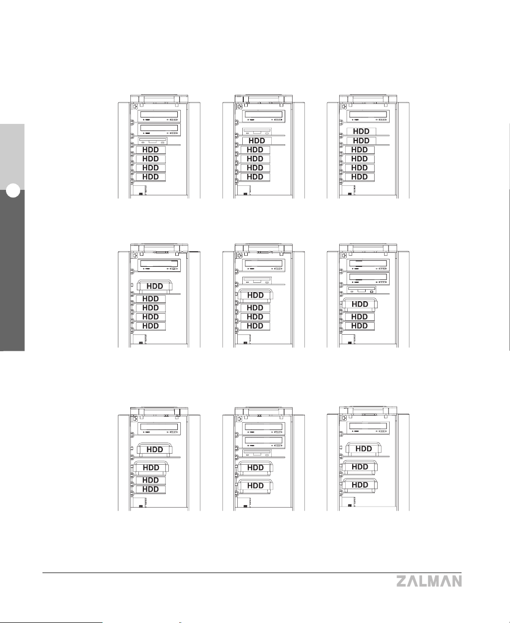
7) Installing the ODD/FDD/HDD
① The ODD/HDD/FDD can be installed as shown in the diagrams below.
ODD 2EA
FDD 1EA
HDD 4EA
❶
ODD 1EA
FDD 1EA
HDD 5EA
❷
ODD 1EA
HDD 6EA
❸
ODD 1EA
HDD Cooler 1EA
HDD 4EA
❹
ODD 1EA
FDD 1EA
HDD Cooler 1EA
HDD 3EA
❺
ODD 2EA
FDD 1EA
HDD Cooler 1EA
HDD 2EA
❻
ODD 1EA
HDD Cooler 2EA
HDD 2EA
❼
ODD 2EA
FDD 1EA
HDD Cooler 2EA
❽
ODD 1EA
HDD Cooler 3EA
❾

35
English
8. Installation Guide
TNN 500AF
② Loosen the bolts (PH M4x12) on the left heatsink slightly and remove the ODD/FDD/HDD
Brackets.
③ Install the Heatpipe HDD Cooler as shown in the diagram.
NOTES) The ground wire MUST be connected to Both the HDD and the Damper as shown.
Brackets
Bolt (PH M4x12)
Left Heatsink
Plate
Brackets
Bolt (FH #6-32X13)
Damper
Bolt (PH #6-32X7)
ZM-2HC2
Ground Wire
Bracket
36
English
8. Installation Guide
TNN 500AF
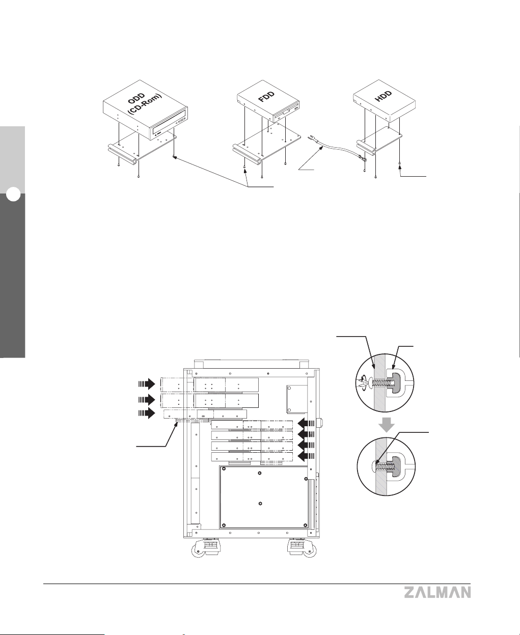
④ Install the ODD/FDD/HDD on the Brackets.
⑤ Insert the ODD/FDD/HDD installed Brackets in the direction shown in the diagram, and re-fasten
the Bracket fixing bolts (PH M4x12) on the Left Heatsink Plate completely.
NOTE) Remember to connect the Ground Wire to the HDD.
Bolt(PH M3X10)
Left Heatsink Plate
Ground Wire
Bolt
(PH #6-32X7)
ODD/FDD/HDD
installed Brackets
Bracket
Bolt
(PH M4x12)

37
English
8. Installation Guide
TNN 500AF
⑥ Connect the Ground Wire to the right heatsink.
Common Finger Bolt
Ground Wire
8) Installing PCI Cards
Insert the PCI cards into the PCI slots and fix them firmly in place using the card fixing bolts.

38
English
8. Installation Guide
TNN 500AF
9) Connecting the Power & Data Cables
① Check whether the power connector on the motherboard is a 24 pin or 20 pin type connector and
connect the appropriate Motherboard Power Cable.
② Connect the various power and data cables as needed.
Sensor Connector
Motherboard Power
Cable (24 Pin)
Motherboard Power
Cable (20 Pin)
Power
Supply

39
English
8. Installation Guide
TNN 500AF
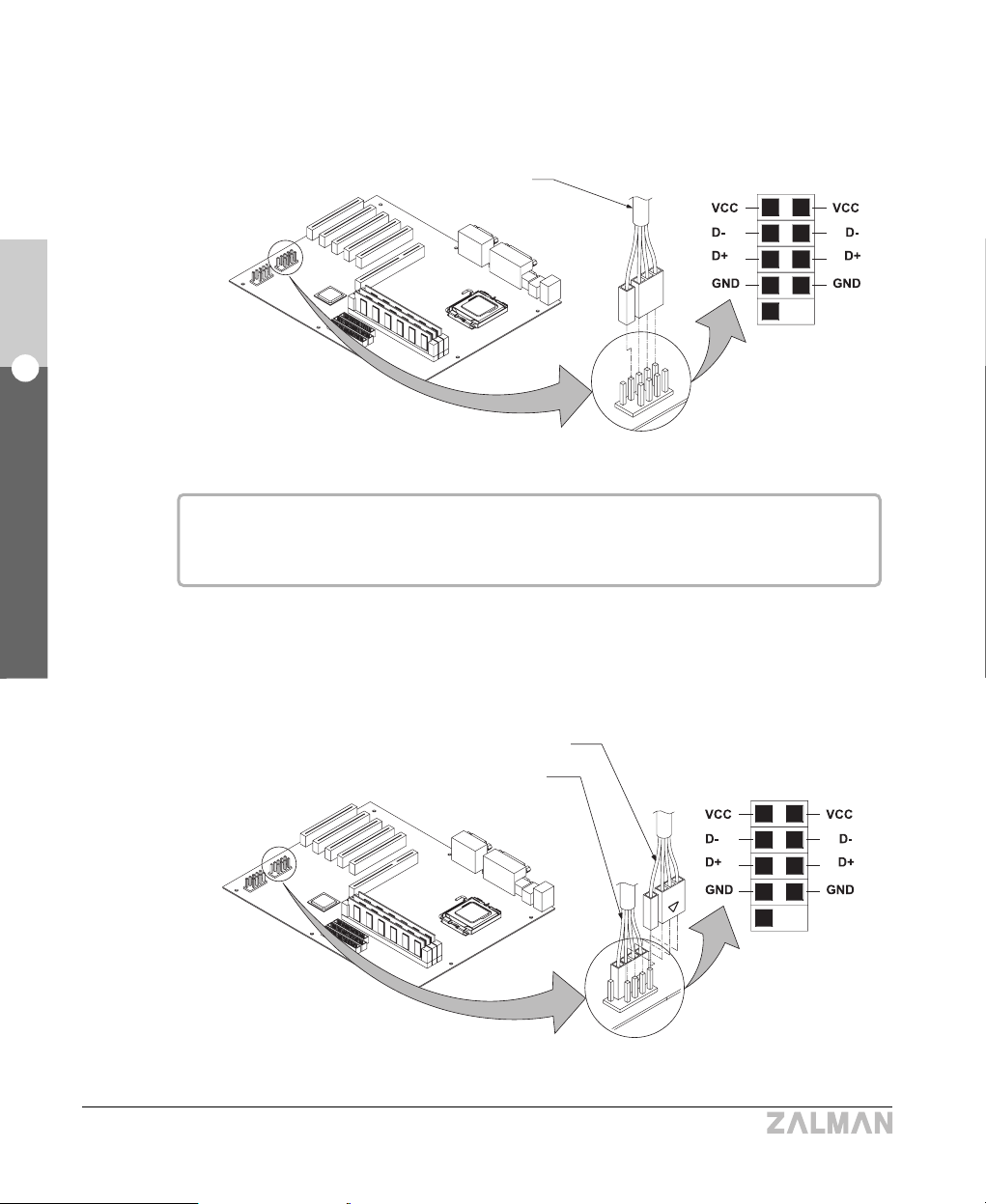
10) Connecting the Remote Control receiver and USB Cables
① To Use the Remote Control Function
- Plug the Dual USB-A Connector into the Dual USB Port on the motherboard(M/B).
▶ Two Available Dual USB Port on the Motherboard
Note)
1) As shown below, there are two types of USB cables (USB-A & USB-B).
Please connect the cables according to the instructions in this guide.
2) Verify the location and the layout of the USB headers from the motherboard manual.
M/B Dual
USB Port
M/B
Dual USB-A Connector
Dual USB-A Cable Dual USB-B Cable
40
English
8. Installation Guide
TNN 500AF
M/B
- Plug the Remote Control USB Connectors into the Dual USB Port on the motherboard.
- Next to where the Remote Control USB Connectors have been connected, on the same Dual
USB Port, connect the Single USB-B Connectors that have the ‘△’marking.
Remote Control USB Connectors
M/B Dual
USB Port
Color codes
VCC : red (yellow), D- : white (orange), D+ : green (blue), GND : black
‘△’Single USB-B Connector
Remote Control USB Connectors
M/B Dual
USB Port
M/B

41
English
8. Installation Guide
TNN 500AF
- Plug in the Dual USB-A and USB-B Connectors into their respective ports on the back of the
Switch Panel.
USB ports #1 through #3 (see diagram) can be used in this configuration.
Dual USB-A Connector
Dual USB-B
Connector
Switch Panel
Back Side
(0) (0) (0) (X)
Front Side
② To Sacrifice the Remote Control Function
- Plug the Dual USB-A Connector and the Dual USB-B Connectors into each of the Dual USB
Ports on the motherboard.
M/B Dual
USB Port
M/B Dual
USB Port
M/B
Dual USB-A Connector
Dual USB-B
Connectors
1) Verify the location and the layout of the USB headers from the motherboard manual.
2) Color codes
VCC : red (yellow), D- : white (orange), D+ : green (blue), GND : black

42
English
8. Installation Guide
TNN 500AF
- Plug in the Dual USB-A and USB-B Connectors into their respective ports on the back of the
Switch Panel.
All of the USB ports (see diagram) can be used in this configuration.
Dual USB-A Connector
Dual USB-B
Connector
Switch Panel
Back Side
(0) (0) (0) (0)
Front Side
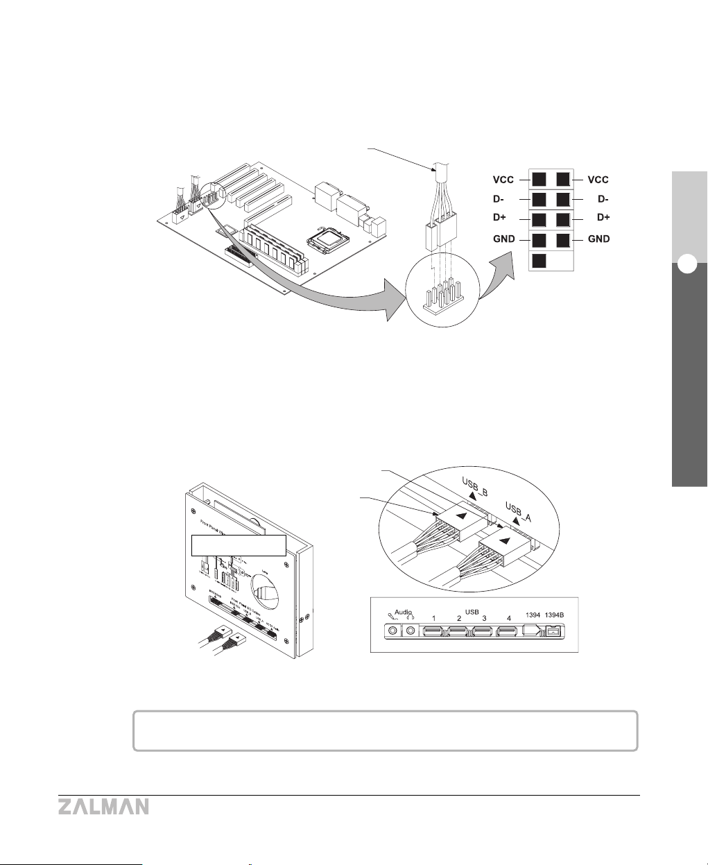
① Plug the Dual USB-A Connector and the Dual USB-B Connectors into each of the Dual
USB Ports on the motherboard.
M/B Dual
USB Port
M/B Dual
USB Port
M/B
Dual USB-A Connector
Dual USB-B
Connectors
1) Verify the location and the layout of the USB headers from the motherboard manual.
2) Color codes : VCC : red (yellow), D- : white (orange), D+ : green (blue), GND : black
▶ Three Available Dual USB Port on the Motherboard
43
English
8. Installation Guide
TNN 500AF
② In the remaining Dual USB Port on the motherboard, connect the Remote Control USB
Connectors.
③ Plug in the Dual USB-A and USB-B Connectors into their respective ports on the back
of the Switch Panel.
Remote Control USB Connectors
M/B Dual
USB Port
M/B
Dual USB-A Connector
Dual USB-B
Connector
Switch Panel
Back Side
(0) (0) (0) (0)
Front Side
All of the USB ports (see diagram) can be used in this configuration.
44
English
8. Installation Guide
TNN 500AF
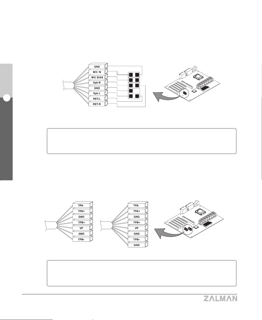
11) Connecting Audio I/O, IEEE1394, and IEEE1394B Cables
① Plug the Audio I/O Connectors onto the Audio Port on the motherboard.
Caution : The audio headers arrangement may differ among motherboards.
Check the motherboard’s manual for correct header arrangement First.
② Plug the IEEE1394/IEEE1394B Connectors onto the IEEE1394/IEEE1394B Port on the
motherboard.
Caution : The IEEE1394 / IEEE1394B headers arrangement may differ among motherboards.
Check the manual for correct header arrangement first.
Color codes :
GND : Black, MIC : Orange, MIC BIAS : Red, Spk-R : Green,
Spk-L : Yellow, RET-L : Brown, RET-R : Blue
Color codes :
TPA - : Green, TPA + : Red, GND : Black, VP : White,
TAPB + : Orange, TAPB - : Blue
Audio I/O
Connectors
Audio Port
M/B
IEEE1394 Connectors
IEEE1394B Connectors
IEEE1394 / IEEE1394B Ports
M/B
45
English
8. Installation Guide
TNN 500AF
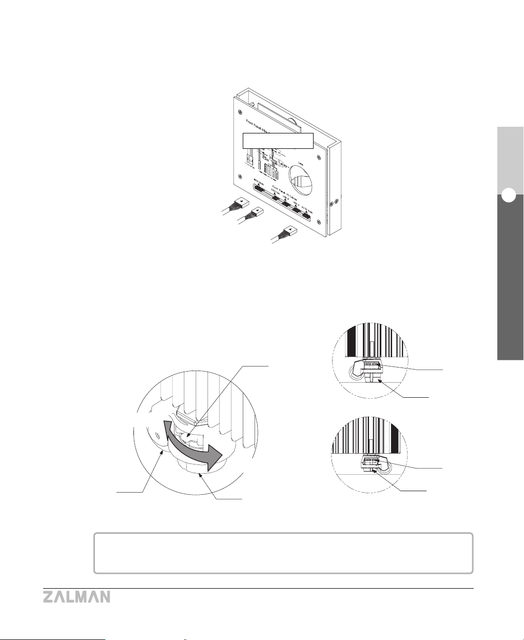
③ Plug the other end of the audio I/O, IEEE1394 & 1394B cables into the back side of the
Switch Panel. Note the arrows for orientation.
12) Use Casters
The Casters’ level can be adjusted to either fix the TNN500AF in place or make it move freely.
Leveler
Mount
Wheel
Leveler
Mount
Leveler
Mount
1. Fix
2. Move
Fix
Move
Switch Panel
If the TNN500AF cannot be installed on a flat surface, the leveler can be used to make it
level; doing so also reduces noise from vibration.

46
English
8. Installation Guide
TNN 500AF
13) Using the Remote Control
Refer to the iMON & Multi-Median User’s Guide for Details.

47
English
9. Trademarks and Copyright Notice
TNN 500AF
9
Trademarks and Copyright Notice
All trademarks are the properties of their respective owner’s.
- ZALMAN and TNN are registered trademarks of ZALMAN Tech Co., Ltd.
- Intel, Pentium, and Prescott are registered trademarks of Intel Corporation.
- Microsoft, and Microsoft Windows 95/98/Me/2000/NT/XP are registered trademarks of Microsoft
Corporation.
- AMD, AMD64, and AMD Athlon64 are registered trademarks of AMD Corporation.
- PS/2, and VGA are registered trademarks of International Business Machines Corporation (IBM).
- NVDIA, GeForce, GeForce2, GeForce3-MX, GeForce-Ti, GeForceFX, GeForce PCX are
registered trademarks of NVIDIA Corporation.
- PCI Express is a registered trademark of PCI-SIG Corporation.
- Matrox, and Parhelia are registered trademarks of Matrox Graphics Inc.
- ATI, and ATI Radeon are registered trademarks of ATI Technologies Inc.
- Unitech is a registered trademark of Unitech Corporation.
- Bytel is a registered trademark of Bytel Electronics, Co., Ltd.
- ASUS is a registered trademark of ASUSTek Computer Inc.
- Samsung is a registered trademark of Samsung Corporation.
- Seagate is a registered trademark of Seagate Technology LLC.
2004 by Zalman Tech Co., Ltd.
Copying or publishing this user’s guide without consent of Zalman Tech Co., Ltd.
is prohibited.
 Loading...