

Page 1

YASKAWA
Auto Transfer File Creation Tool for MP2000 Series Machine Controller
MPLoad Maker
USER'S MANUAL
TYPE: CPMC-MPL710
YASKAWA
MANUAL NO. SIEP C880781 02B
Page 2

Copyright © 2006 YASKAWA ELECTRIC CORPORATION
All rights reserved. No part of this publication may be reproduced, stored in a retrieval system,
or transmitted, in any form, or by any means, mechanical, electronic, photocopying, recording,
or otherwise, without the prior written permission of Yaskawa. No patent liability is assumed
with respect to the use of the information contained herein. Moreover, because Yaskawa is constantly striving to improve its high-quality products, the information contained in this manual is
subject to change without notice. Every precaution has been taken in the preparation of this
manual. Nevertheless, Yaskawa assumes no responsibility for errors or omissions. Neither is
any liability assumed for damages resulting from the use of the information contained in this
publication.
Page 3

Contents
1 Introduction to MPLoad Maker - - - - - - - - - - - - - - - - - - - - - - - - 4
1.1 Overview - - - - - - - - - - - - - - - - - - - - - - - - - - - - - - - - - - - - - - - - - - - - - - -4
1.2 Features - - - - - - - - - - - - - - - - - - - - - - - - - - - - - - - - - - - - - - - - - - - - - - -4
1.3 Specifications - - - - - - - - - - - - - - - - - - - - - - - - - - - - - - - - - - - - - - - - - - -5
2 Installing MPLoad Maker - - - - - - - - - - - - - - - - - - - - - - - - - - - - 6
3 Starting and Exiting MPLoad Maker - - - - - - - - - - - - - - - - - - - - 7
3.1 Starting MPLoad Maker - - - - - - - - - - - - - - - - - - - - - - - - - - - - - - - - - - - -7
3.2 Exiting MPLoad Maker - - - - - - - - - - - - - - - - - - - - - - - - - - - - - - - - - - - - -7
4 Creating Auto_MPLCD - - - - - - - - - - - - - - - - - - - - - - - - - - - - - 8
4.1 Communications Settings for Target PC - - - - - - - - - - - - - - - - - - - - - - - - -8
4.2 Creating Auto_MPL - - - - - - - - - - - - - - - - - - - - - - - - - - - - - - - - - - - - - - 11
4.3 Creating Auto_MPLCD - - - - - - - - - - - - - - - - - - - - - - - - - - - - - - - - - - - - 16
4.4 Starting Auto_MPL - - - - - - - - - - - - - - - - - - - - - - - - - - - - - - - - - - - - - - - 17
5 Creating .BAT File Executable from HDD - - - - - - - - - - - - - - - - -20
5.1 Communications Settings for Target PC - - - - - - - - - - - - - - - - - - - - - - - - 20
5.2 Creating .BAT File - - - - - - - - - - - - - - - - - - - - - - - - - - - - - - - - - - - - - - -20
5.3 Copying .BAT File to Target PC - - - - - - - - - - - - - - - - - - - - - - - - - - - - - - 26
5.4 Starting .BAT File - - - - - - - - - - - - - - - - - - - - - - - - - - - - - - - - - - - - - - - -26
A Creating a .Mal File (Compressed File) for MPE720 Ver.5
Application - - - - - - - - - - - - - - - - - - - - - - - - - - - - - - - - - - - - - -28
A.1 Creating a .Mal File for Batch Transfer - - - - - - - - - - - - - - - - - - - - - - - - -28
A.2 Creating a .Mal File for Individual Transfer - - - - - - - - - - - - - - - - - - - - - - 31
B Transfer Setting for Project File Created Using MPE720 Ver.6 -34
C Error Messages and Troubleshooting - - - - - - - - - - - - - - - - - - -35
C.1 Error Messages Displayed on a PC with MPLoad Maker installed - - - - -35
C.2 Error Messages Displayed on the Target PC - - - - - - - - - - - - - - - - - - - - 35
Revision History
Related Manuals
■
The following table lists the manuals relating to the MPLoad Maker. Refer to these manuals as required.
Manual Name Manual Number Contents
Machine Controller MP900/MP2000 Series
MPE720 Software for Programming Device
User’s Manual
Engineering Tool for
MP2000 Series Machine Controller
MPE720 Version6 User’s Manual
Copyrights
■
SIEP C880700 05
SIEP C880700 30
Describes how to install and operate the MP900/
MP2000 Series programming system (MPE720
Ve r. 5 ).
Describes how to install and operate the MP2000
Series Engineering Tool (MPE720 Ver.6).
• Windows and Windows XP are registered trademarks of the Microsoft Corporation.
• Pentium is a registered trademark of the Intel Corporation.
• Other product names and company names are the trademarks or registered trademarks of the respective company. “TM”
and the
mark do not appear with product or company names in this manual.
®
3
Page 4
Introduction to MPLoad Maker
MP2300
YASKAWA
RDY
ALM
TX
RUN
ERR
BAT
BATTERY
SW1
OFFޓޓޓON
M-I/II
CPUޓI/O
POWER
DC24V
DC0V
STOP
SUP
INIT
CNFG
MON
TEST
218IF-01
ERR
COL
RX
RUN
STRX
TX
INIT
TEST
ONOFF
PORT
10Base-T
LIO-04
FURUN
CN1
CN2
SVB-01
TX
ERRRUN
SPD
SIZE
M/S
ON
OFF
10
1
M-I/II
CN1
CN2
MP2000-series Machine Controllers
Target PC
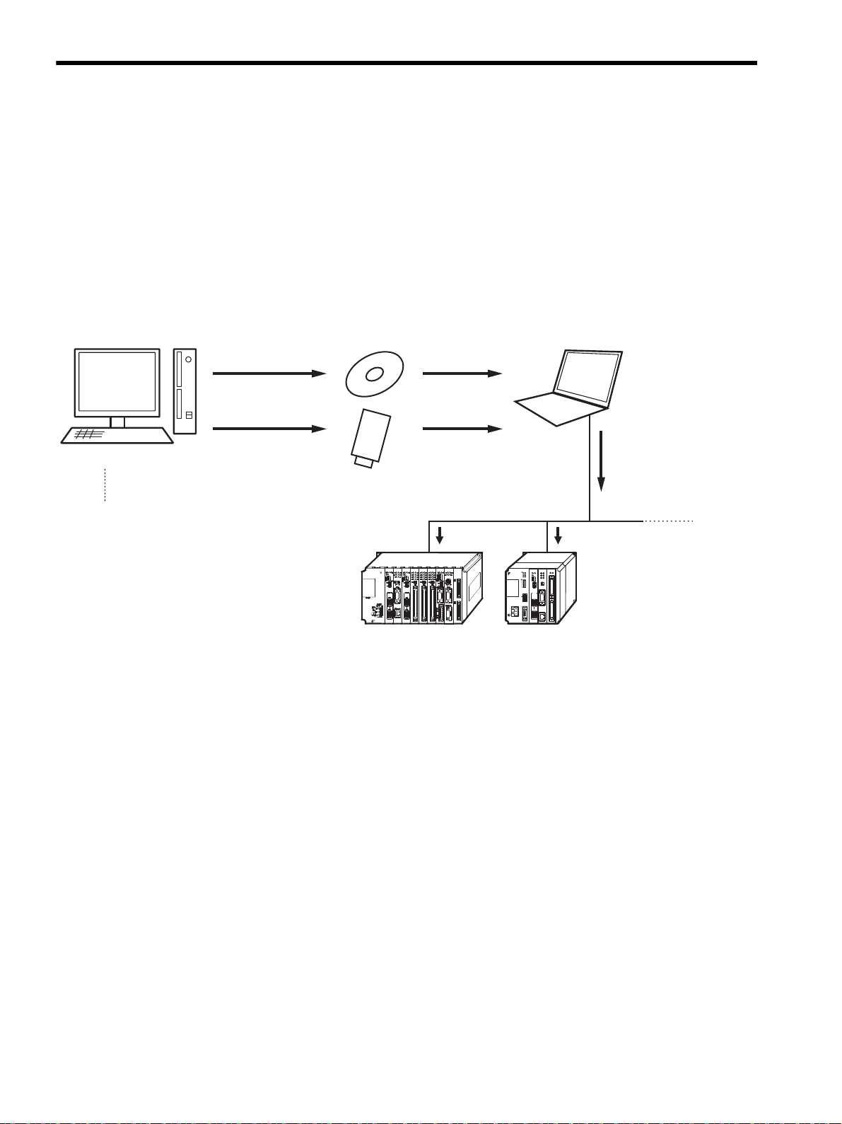
Auto_MPLCD
PC with MPLoad Maker
Write the Auto-MPL
onto a CD-ROM.
Insert the Auto_MPLCD
into the CD-ROM drive.
Write onto a general-purpose
flash memory card (USB).
Copy
㧔MPLoad Maker㧕
RS-232C communications,
Ethernet communications, or
USB commnications
Create the Auto-MPL (auto start file)
using the application for MP2000-series
Machine Controller.
Auto-MPL automatically
starts to transfer the
application.
MP2200
MBU-01
POWER
SVB-01
SVB-01
218F-01
LIO-02
LIO-01
LIO-01
217F-01
EXIOIF
260F-01
Y
ASKAWA
1
Overview
1.1
1 Introduction to MPLoad Maker
1.1 Overview
MPLoad Maker is a tool which allows the user to create an auto start file (Auto_MPL) using the application data for the
MP2000-series Machine Controller created by the Personal Computer (PC). When the created Auto_MPL is written
on the CD-ROM and the CD-ROM (hereinafter referred to as MPLCD) is inserted into the CD-ROM drive of the PC
connected to a Machine Controller (hereinafter referred to as target PC), AUTO_MPL will open the application
automatically and transfer the application to the target Machine Controller.
Instead of using Auto_MPL written on the CD-ROM, you can use the .BAT file writen on other media or on the HDD.
The application is transferred as illustrated below.
1.2 Features
MPLoad Maker features the following:
4
MPLoad Maker can not be used to reuse rewritable disks. A CD-RW device or driver is required to write the
Auto_MPL onto a CD-ROM.
• Application transfer without installing a tool such as MPE720 or MPLoader in the Target PC.
• Application transfer to multiple Machine Controllers using a single Auto_MPLCD.
• As the functions of Auto_MPL are limited to opening and transfering the application, the application will not
be overwritten adversely in the Target PC.
Page 5

1.3 Specifications
The following table provides the specifications of MPLoad Maker.
Applicable Machine Controllers MP2100, MP2100M, MP2200 (with CPU-01/02), and MP2300
CPU Pentium II 400 MHz min.
Minimum Required RAM 128 MB
Minimum Required Display
Resolution
Supported Operating Systems
Supported Communications
Interfaces or Modules
Transferable File Types
Application Continuous Transfer
Function
Memory Required for Installation 30 MB None (Installation is not necessary.)
Hard Drive Space Required for
Create/Transfer
Introduction to MPLoad Maker
1
Item PC with MPLoad Maker Target PC
800×600
Windows 98SE
・
Windows 2000
(Japanese or English version)
Windows 2000
・
(Japanese or English version)
Windows XP
・
(Japanese or English version)
−
.MAL file (compressed MAL file of MPE720 Ver.5 application)
.YMW file (MPE720 Ver. 6 project file)
−
25 MB +
*2 (per Auto_MPL)
α
・
(Japanese or English version)
Windows XP
・
(Japanese or English version)
Serial communications interface
217IF-01
218IF-01
260IF-01
261IF-01
215AIF-01
Ethernet communications interface
218IF-01
USB interface
MP2200 (with CPU-02 Module)
MP2100 interface
MP2100
MP2100M
Provided
1 MB +
ically at completion of transfer.)
*1
*1
*1
*2
(Data will be deleted automat-
α
Specifications
1.3
* 1. The relay setting is not supported.
* 2. Depends on the size of application to be transferred.
5
Page 6
Installing MPLoad Maker
2
Specifications
1.3
2 Installing MPLoad Maker
Use the following procedure to install MPLoad Maker on the PC.
Insert the MPLoad Maker installation CD-ROM into the CD-ROM drive of the PC.
1.
Open the ENG folder and then MPLOADMAKER folder in the CD-ROM using Explorer. Double-click
2.
Setup.exe file in the folder.
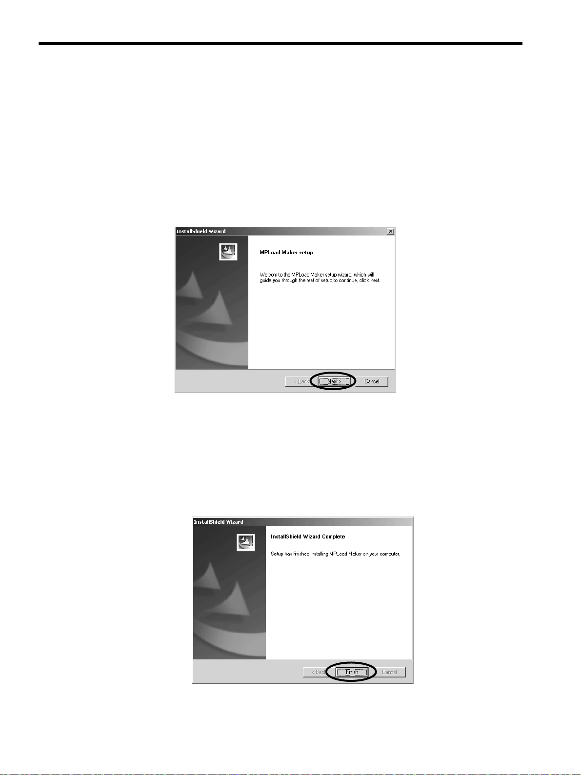
The MPLoad Maker Installer will start. The InstallShield Wizard following the Title Window will then be displayed.
Click the Next Button if you are using the default settings of the installation destination folder and
3.
program folder.
Installation will start. When the installation completes, the InstallShield Wizard Complete message will be displayed.
Default setting: Installation destination folder “C:\YeTools,” Program folder “YE_Applications”
Click the Finish Button.
4.
MPLoad Maker has now been installed. Remove the installation CD-ROM from the CD-ROM drive.
6
Page 7
3 Starting and Exiting MPLoad Maker
Use the following procedures to start and exit the MPLoad Maker.
3.1 Starting MPLoad Maker
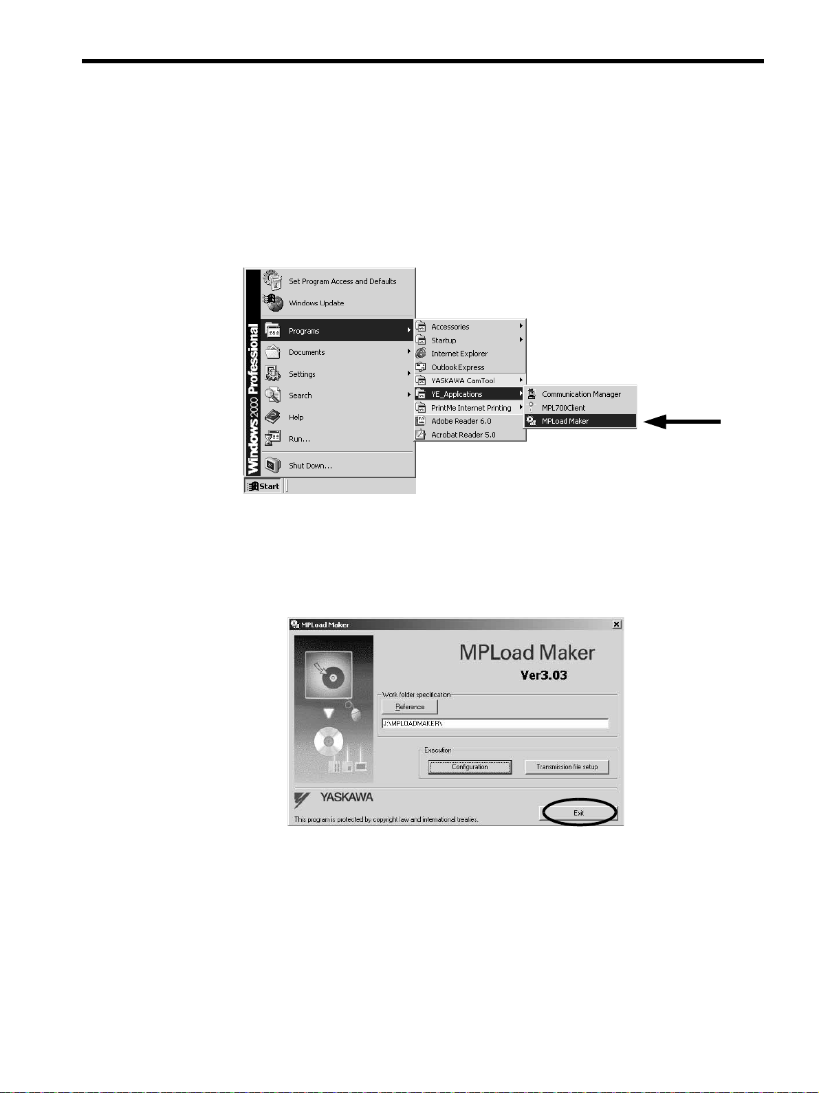
Click the Start Button and select Programs - YE_Applications - MPLoad Maker.
1.
Starting and Exiting MPLoad Maker
3
Starting MPLoad Maker
3.1
MPLoad Maker will start and the main window will be displayed.
3.2 Exiting MPLoad Maker
Click the Exit Button in the main window.
1.
7
Page 8
Creating Auto_MPLCD
4
Communications Settings for Target PC
4.1
4 Creating Auto_MPLCD
This chapter explains how to create the Auto_MPL file using MPLoad Maker and write it onto a CD-ROM to create
the Auto_MPLCD.
4.1 Communications Settings for Target PC
Start MPLoad Maker to make the communications settings for the Target PC. A serial communications interface, 218
communications module (Ethernet), MP2100 interface, or USB can be used for communications between the Target
PC and the Machine Controllers.
Check the following before setting: Target PC IP address, serial port (COM port) number used for communications
between Target PC and Machine Controllers, and CP number where the MP2100 Module is mounted when using a
MP2100 Module.
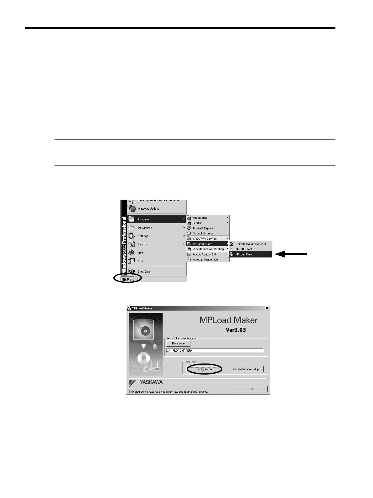
Click the Start Button and select Programs - YE_Applications - MPLoad Maker to start MPLoad
1.
Maker.
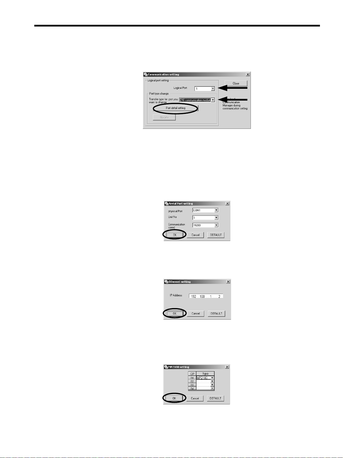
Click the Configuration Button.
2.
The Communication Setting Dialog Box will be displayed.
Refer to 4.2 Creating Auto_MPL on page 11 for details on Work folder specification.
8
Page 9
Creating Auto_MPLCD
4
Communications Settings for Target PC
4.1
Select the logical port number and port type (communications type) used for communications between
3.
the Target PC and Machine Controllers, and then click the Port detail setting Button.
The setting dialog box for the selected port type will be displayed.
Selecting the port type will enable the Port detail setting Button.
When USB is selected as the port type, the Port detail setting Button will be invalid. Proceed to Step 5.
Make the communications settings for the selected port.
4.
<When Serial is selected as the port type>
The Serial Port setting Dialog Box will be displayed. Select the physical port, unit No., and communications speed, and then click the OK Button.
<When the 218 communication module is selected as the port type>
The Ethernet setting Dialog Box will be displayed. Type the IP address of the Target PC, and then
click the OK Button.
<When MP2100 is selected as the port type>
The MP2100 setting Dialog Box will be displayed. Click the arrow ▼ next to the CP number (set by
the dip switch of MP2100) of the transfer destination MP2100 board, select MP2100 from the Typ e
Box, and then click the OK Button.
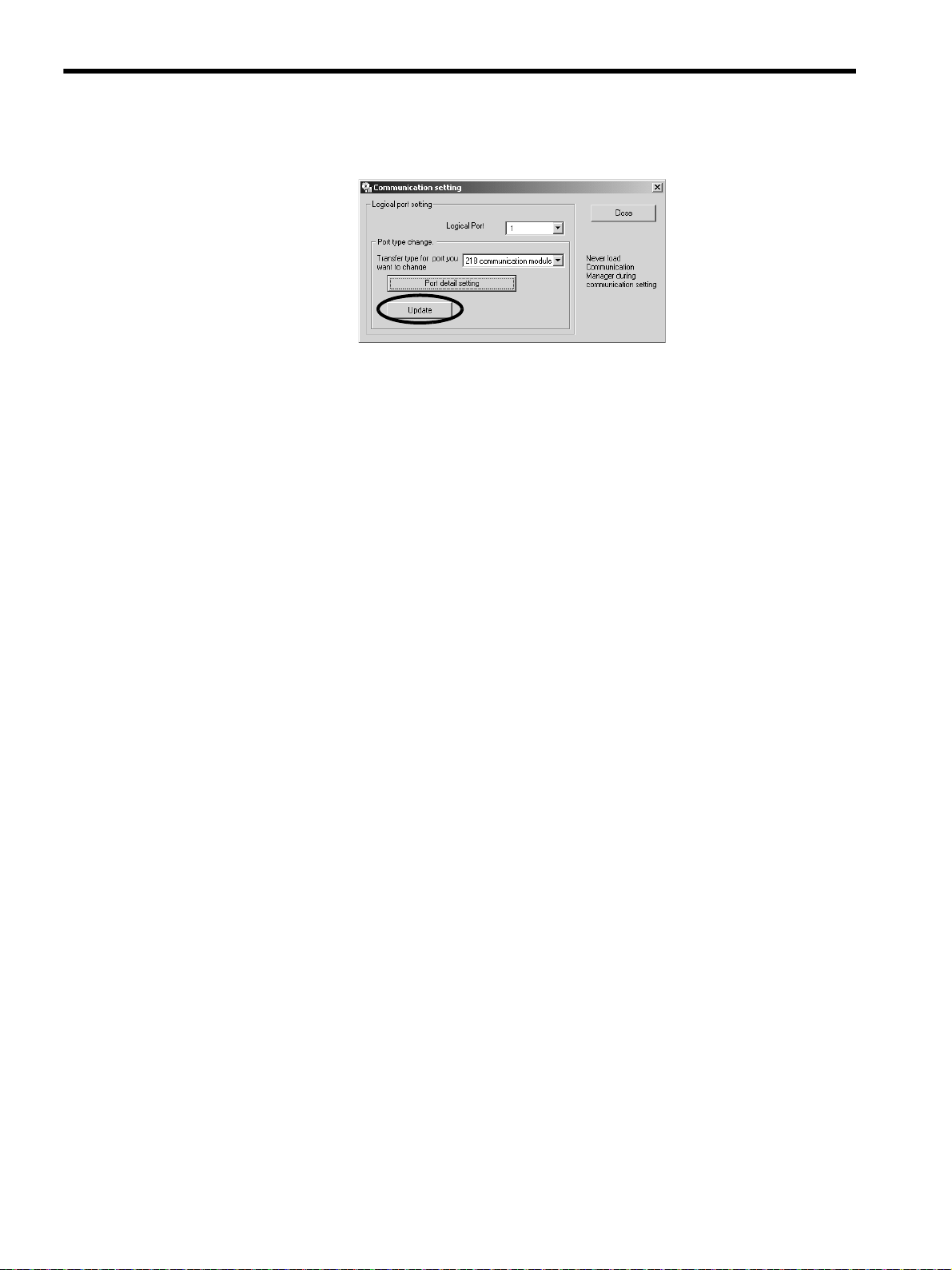
The Communication setting Dialog Box will be displayed again and the Update Button will be enabled.
9
Page 10
Creating Auto_MPLCD
4
Communications Settings for Target PC
4.1
Click the Update Button. A confirmation message will appear. Click the OK Button.
5.
When using more than one port, repeat Steps 3 through 5 to make communications settings for each
6.
port.
Click the Close Button to close the Communication setting Dialog Box.
7.
10
Page 11
4.2 Creating Auto_MPL
Specify the .mal file or .ymw file to be transferred using MPLoad Maker and create the Auto_MPL.
Create a folder (with a desired folder name) to store the Auto_MPL on the hard drive. The Auto_MPL (containing
four sets of data) in one folder will be written into one Auto_MPLCD.
When transferring the MPE720 Ver.5 application, it is necessary to compress the application to create the .mal file.
Refer to A Creating a .Mal File (Compressed File) for MPE720 Ver.5 Application on page 28 for information on how
to create a .mal file.
When transferring the MPE720 Ver. 6 application, the settings for the compression and transfer function of the
MPLoader tool must be made in advance. Refer to B Transfer Setting for Project File Created Using MPE720 Ver.6
on page 34 for information on how to set the compression and transfer function.
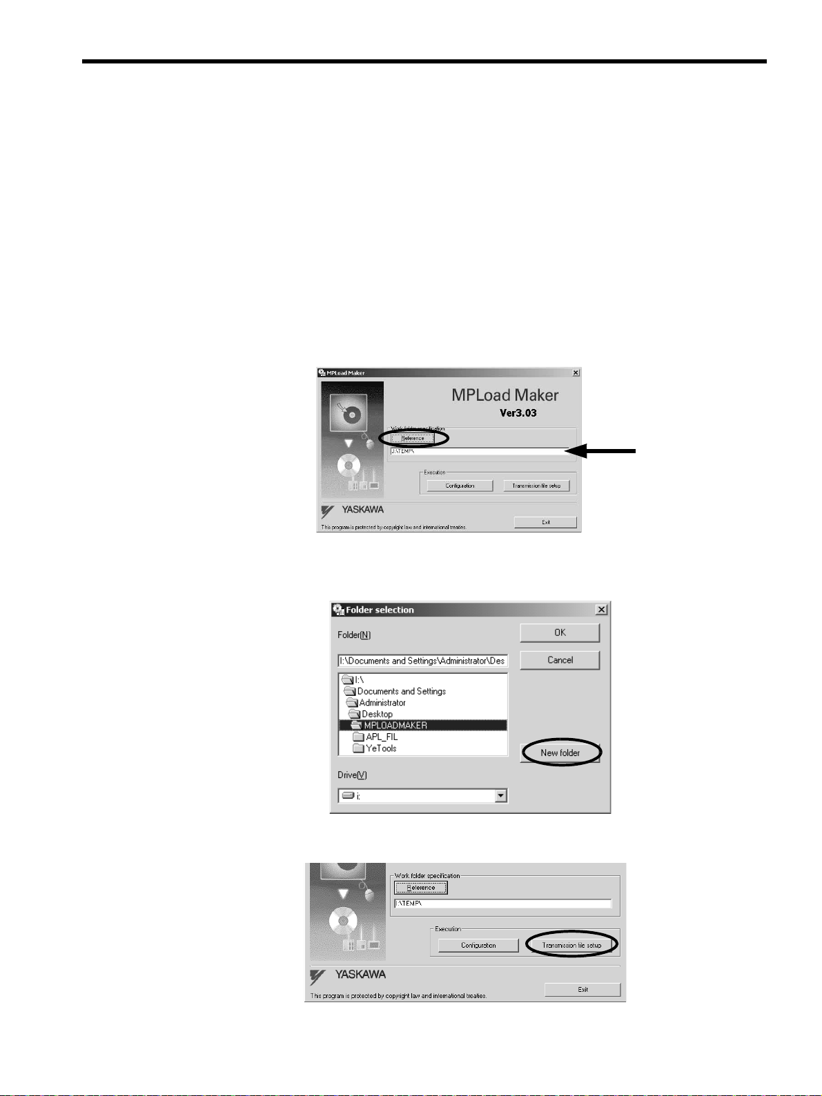
Specify the folder to store the Auto_MPL in the MPLoad Maker main window.
1.
Click the Reference Button under Work folder specification to select the work folder in the Folder
Selection Dialog Box, or type the work folder path into the input field.
Creating Auto_MPLCD
4
Creating Auto_MPL
4.2
When selecting the work folder in the Folder selection Dialog Box, double-click the relevant work
folder and then click the OK Button.
If a work folder has not yet been created, click the New folder Button to create a work folder.
Click the Transmission file setup Button.
2.
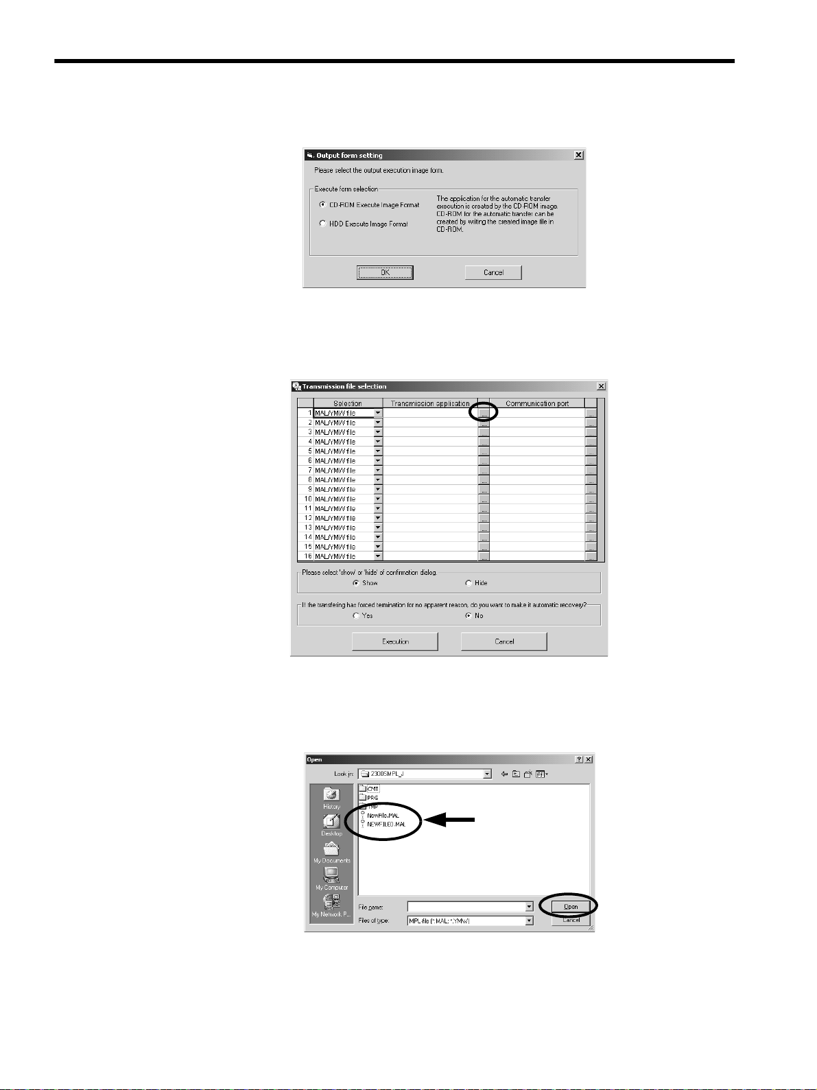
The Output form setting Dialog Box will be displayed.
11
Page 12
Creating Auto_MPLCD
Select only one file.
4
Creating Auto_MPL
4.2
3.
4.
Select the CD-ROM Execute Image Format Option, and then click the OK button.
The Transmission file selection Dialog Box will be dispalyed.
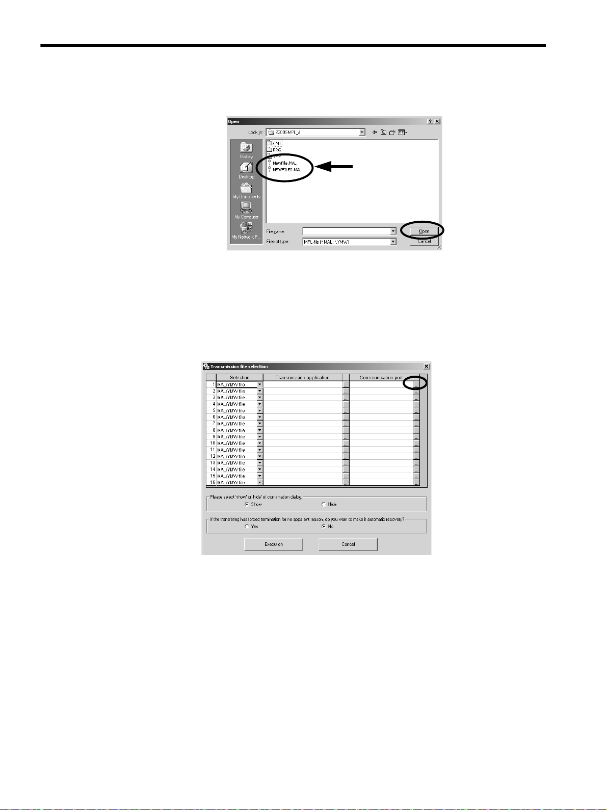
Click the button to the right of the Transmission application column.
12
The Open Dialog Box will be displayed.
Select one .mal or .ymw file to be transferred, and then click the Open Button.
5.
The Transmission file selection Dialog Box will be displayed again.
Page 13

Creating Auto_MPLCD
4
Creating Auto_MPL
4.2
Check the .mal or .ymw file path displayed in the Transmission application column, and then click
6.
the button to the right of the Communication port column.
When the file path is too long to be displayed, drag the frame of the display field. A scroll bar will be displayed
on the bottom of the frame to scroll the display.
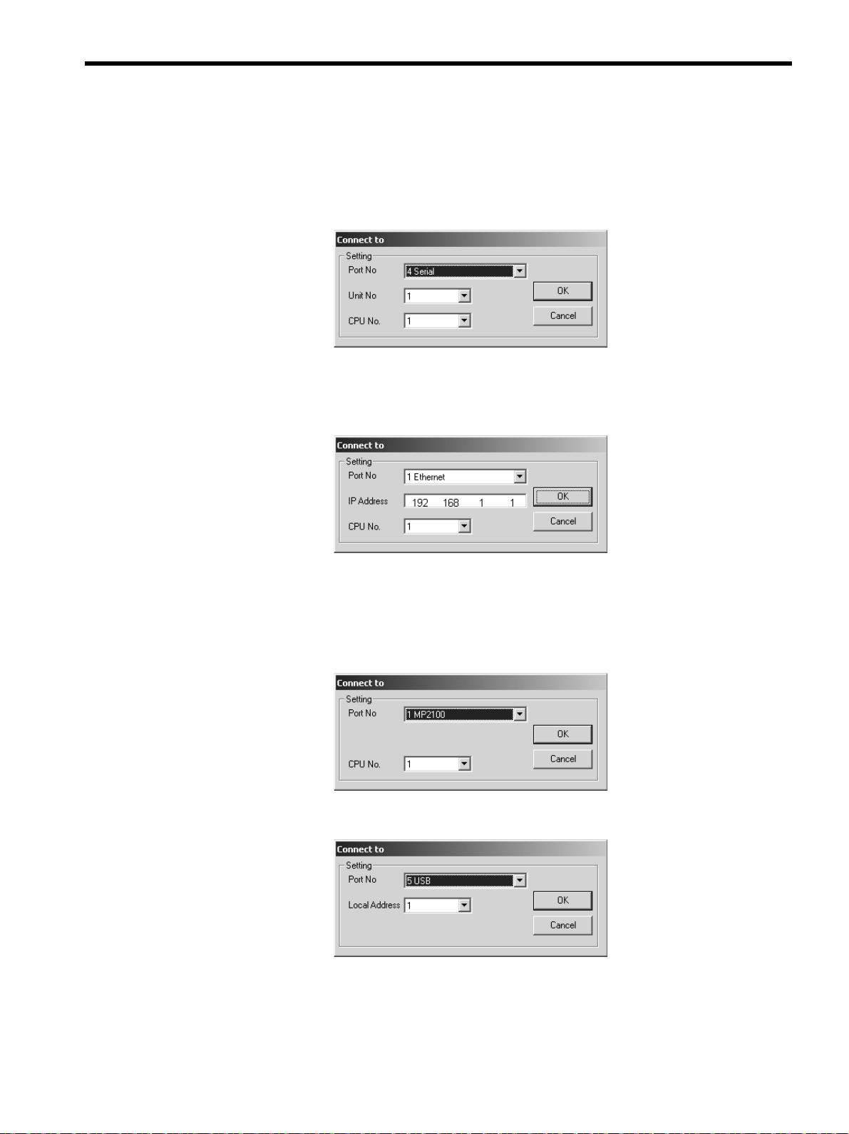
The Connect to Dialog Box will be displayed.
Select the logical port number used for transfer in the Target PC from the Port No Box.
7.
The items to be set will differ depending on the selected port type.
Set the transfer destination Machine Controller (Module).
8.
< When Serial is selected as Port No. >
Unit No.:
Box is displayed. It is possible to change the value
CPU No:
The value set in the setting dialog box of the port type selected in the Communication setting Dialog
.
Select 1
.
< When the 218 communication module is selected as Port No. >
IP Address:
The default setting 192 168 1 1 is displayed. Change the setting to the IP address of the transfer
destination 218IF Module.
CPU No.:
Select 1
.
< When MP2100 is selected as Port No. >
CPU No.: Select the CPU number of the transfer destination Machine Controller. Select a CPU number from the
CP numbers (CPU numbers) in the setting dialog box of the MP2100 (port type) selected in the
Dialog Box.
setting
Selecting a CPU number other than those in the Communication setting Dialog Box will generate an alarm at
execution of transfer.
Communication
13
Page 14

Creating Auto_MPLCD
4
Creating Auto_MPL
4.2
< When USB is selected as Port No. >
Local Address : Select the USB port address of the transfer destination Machine Controller.
Click the OK Button to complete the settings. The
Transmission file selection
Dialog Box will be displayed
again.
The selected logical port number and the contents assigned to the port are displayed in the Communication
port column.
Repeat Steps 3 through 8 to set all the applications to be transferred and the transfer destinations.
9.
Also repeat Steps 3 through 8 (file selection to communications port settings) when setting one application to
multiple transfer destinations.
Do not close the Transmission file selection Dialog Box until the application selection and communications
port settings have been completed and the Auto_MPL has been created by clicking the Execution Button.
Closing the Dialog Box before clicking the Execution Button will delete all the information set for the applica-
tion.
When you have finished selecting all of the applications to be transferred and completed all communi-
10.
cations port settings, click the Execution Button.
When the Show Option is selected under Please select ‘show’ or ‘hide’ of confirmation dialog, the
Confirmation Dialog Box will be displayed when the Auto_MPLCD is inserted in the CD-ROM drive of the
Target PC to check the transfer file names and communications port settings.
If the auto start CD-ROM is forcibly terminated by Windows Task Manager or the Target PC power supply is
turned OFF in the Target PC where the MPE720 is installed, the MPE720 may not be able to run any more.
When the Yes Option is selected under If the transfering has forced termination for no apparent reason,
do you want to make it automatic recovery?, a backup file will be created to restore the original environments so that the MPE720 will start properly in the above case.
14
Page 15

Creating Auto_MPLCD
4
Creating Auto_MPL
4.2
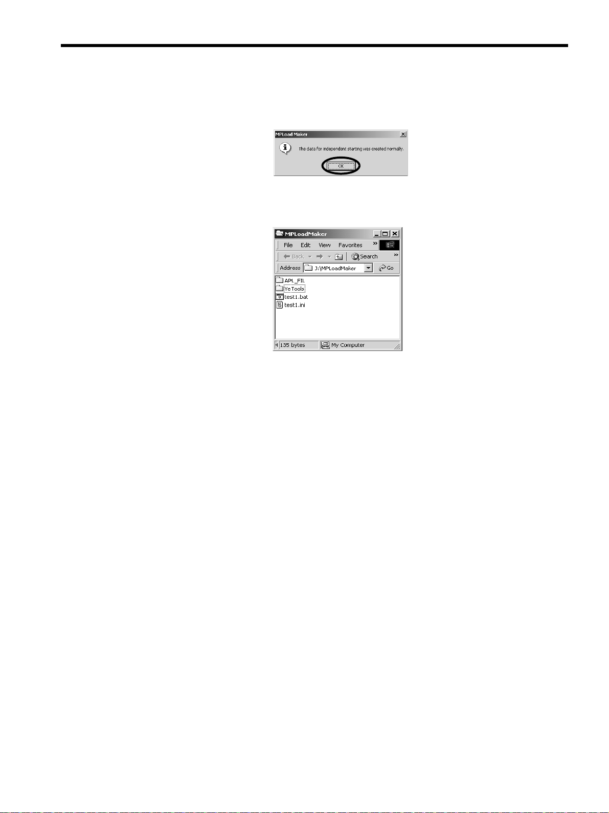
The MPLoad Maker will start creating an Auto_MPL. When the Auto_MPL has been created, the following
message will be displayed. Click the OK Button.
Open the work folder specified in Step 1 and confirm that the folders and files shown below have been
11.
created.
15
Page 16

Creating Auto_MPLCD
4
Creating Auto_MPLCD
4.3
4.3 Creating Auto_MPLCD
Use a CD-RW device or driver to write the created Auto_MPL (shown below) onto a CD-ROM. The Auto_MPL written onto the CD-ROM is called Auto_MPLCD.
Write four sets of data in the work folder onto a CD-ROM.
MPLoad Maker can not be used to reuse rewritable disks.
When writing the Auto_MPL onto a CD-ROM, a message for directory level may appear. If the writing operation is
interrupted, change the settings. For example, change the write directory level to a level higher than 10.
If the created Auto_MPLCD is left in the CD-ROM drive, the Auto_MPL will automatically start running. Be sure to
remove the Auto_MPLCD from the CD-ROM drive when writing is completed.
16
Page 17

4.4 Starting Auto_MPL
When the created Auto_MPLCD is inserted into the CD-ROM drive of the Target PC, Auto_MPL will
automatically launch, and the application will be extracted and transferred to the Machine Controller.
If the Communication Manager (Communication Process) has been installed in the Target PC, close it before insert-
ing Auto_MPLCD into the CD-ROM drive. If the Communication Manager is open when Auto_MPLCD is inserted
into the CD-ROM drive, the following message will appear and an error will occur.
Check the task bar for the Communication Manager Icon. If the Communication Manager Icon is displayed, the
Communication Manager is open. Right-click the Communication Manager Icon and select Exit. A confirmation
message will appear. Click the Yes Button.
Creating Auto_MPLCD
4
Starting Auto_MPL
4.4
Inserting the created Auto_MPLCD into the CD-ROM drive of the Target PC will automatically open Auto_MPL. The
program or project file in Auto_MPL will be automatically decompressed and transferred to the Machine Controllers.
During the transfer, the
Clicking the Cancel Button on the above dialog box will abort the transfer.
MPL700 Client 2: File Transfer
Dialog Box will be displayed.
When the transfer is complete, the following list will be displayed. Check to confirm if the transfer was completed successfully or failed.
17
Page 18

Creating Auto_MPLCD
4
Starting Auto_MPL
4.4
The transfer will fail in the following cases.
・
・
・
・
・
The actual IP address is different from the address set when creating the Auto_MPL.
The actual serial port (COM port) number is different from the number set when creating the Auto_MPL.
The actual CPU number is different from the number set when creating the Auto_MPL.
The actual USB address is different from the address set when creating the Auto_MPL.
The Target PC is not connected to the transfer destination Machine Controllers.
18
Page 19
Creating Auto_MPLCD
4
Starting Auto_MPL
4.4
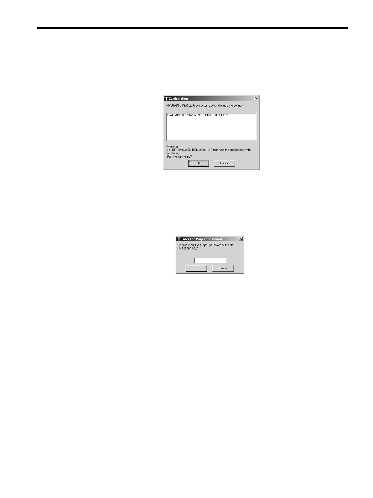
If Displaying the Confirmation Dialog Box
If the Show option is selected under Please select ‘show’ or ‘hide’ confirmation dialog in the Transmission file
selection Dialog Box when creating the Auto_MPL, the Confirmation Dialog Box will be displayed to check the
transfer contents when inserting the created Auto_MPLCD into the CD-ROM drive of the Target PC.
OK Button:
Cancel Button:
If a Password Has Been Set for .Ymw File
If a project password has been set for the .ymw file, the following dialog box will be displayed when inserting the created Auto_MPLCD into the CD-ROM drive of the Target PC, and you will be prompted to type the project password.
Type the correct password and click the OK Button. The transfer will begin.
Click the Cancel Button to cancel the transfer.
If Optional Setting of Writing onto Flash Memory after Transfer Is Made for .Mal or .Ymw File
If the Write in flash memory after transfer Check Box was selected when creating created the .mal file using the
MPE720 Ver.5 or if the The flash saving is executed after transfer Check Box was selected in the detail setting window opened by selecting Transfer - MPLoader from the tree in the Environment Setting Dialog Box for the .ymw
file (project file) created using the MPE720 Ver.6, the data transferred to the Machine Controller will be saved in the
flash memory of the Machine Controller.
Click this button to continue the transfer
Click this button to cancel the transfer
.
.
19
Page 20

Creating .BAT File Executable from HDD
5
Communications Settings for Target PC
5.1
5 Creating .BAT File Executable from HDD
This chapter explains how to create a .BAT file that is executable from the HDD using MPLoad Maker.
Create a folder (with a desired folder name) to store the .BAT file on the hard drive.
When transferring the MPE720 Ver.5 application, it is necessary to compress the application to create the .mal file.
Refer to A Creating a .Mal File (Compressed File) for MPE720 Ver.5 Application on page 28 for information on how
to create a .mal file.
When transferring the MPE720 Ver. 6 application, the settings for the compression and transfer function of the
MPLoader tool must be made in advance. Refer to B Transfer Setting for Project File Created Using MPE720 Ver.6
on page 34 for information on how to set the compression and transfer function.
5.1 Communications Settings for Target PC
Refer to
4.1 Communications Settings for Target PC
5.2 Creating .BAT File
Specify the .mal file or .ymw file to be transferred using MPLoad Maker and create the .BAT file.
Specify the folder to store the .BAT file in the MPLoad Maker main window.
1.
Click the Reference Button under Work folder specification to select the work folder in the Folder
Selection Dialog Box, or type the work folder path into the input field.
When selecting the work folder in the Folder selection Dialog Box, double-click the relevant work
folder and then click the OK Button.
If a work folder has not yet been created, click the New folder Button to create a work folder.
on page 8
.
20
Page 21

Creating .BAT File Executable from HDD
5
Creating .BAT File
5.2
Click the Transmission file setup Button.
2.
The Output form setting Dialog Box will be displayed.
Select the HDD Execute Image Format Option, input the .BAT file name (test1 in the example below),
3.
then click the OK Button.
Click the button to the right of the Transmission application column.
4.
The Open Dialog Box will be displayed.
21
Page 22
Creating .BAT File Executable from HDD
Select only one file.
5
Creating .BAT File
5.2
Select one .mal or .ymw file to be transferred, and then click the Open Button.
5.
The Transmission file selection Dialog Box will be displayed again.
Check the .mal or .ymw file path displayed in the Transmission application column, and then click
6.
the button to the right of the Communication port column.
When the file path is too long to be displayed, drag the frame of the display field. A scroll bar will be displayed
on the bottom of the frame to scroll the display.
22
The Connect to Dialog Box will be displayed.
Select the logical port number used for transfer in the Target PC from the Port No Box.
7.
The items to be set will differ depending on the selected port type.
Page 23
Set the transfer destination Machine Controller (Module).
8.
< When Serial is selected as Port No. >
Unit No.:
Box is displayed. It is possible to change the value
CPU No:
The value set in the setting dialog box of the port type selected in the Communication setting Dialog
.
Select 1
.
< When the 218 communication module is selected as Port No. >
IP Address:
The default setting 192 168 1 1 is displayed. Change the setting to the IP address of the transfer
destination 218IF Module.
CPU No.:
Select 1
.
Creating .BAT File Executable from HDD
5
Creating .BAT File
5.2
< When MP2100 is selected as Port No. >
CPU No.: Select the CPU number of the transfer destination Machine Controller. Select a CPU number from the
CP numbers (CPU numbers) in the setting dialog box of the MP2100 (port type) selected in the
Dialog Box.
setting
Selecting a CPU number other than those in the Communication setting Dialog Box will generate an alarm at
execution of transfer.
Communication
< When USB is selected as Port No. >
Local Address : Select the USB port address of the transfer destination Machine Controller.
23
Page 24

Creating .BAT File Executable from HDD
5
Creating .BAT File
5.2
Click the OK Button to complete the settings. The
Transmission file selection
Dialog Box will be displayed
again.
The selected logical port number and the contents assigned to the port are displayed in the Communication
port column.
Repeat Steps 3 through 8 to set all the applications to be transferred and the transfer destinations.
9.
Also repeat Steps 3 through 8 (file selection to communications port settings) when setting one application to
multiple transfer destinations.
Do not close the Transmission file selection Dialog Box until the application selection and communications
port settings have been completed and the .BAT file has been created by clicking the Execution Button. Closing the Dialog Box before clicking the Execution Button will delete all the information set for the application.
When you have finished selecting all of the applications to be transferred and completed all communi-
10.
cations port settings, click the Execution Button.
When the Show Option is selected under Please select ‘show’ or ‘hide’ of confirmation dialog, the
Confirmation Dialog Box will be displayed when the .BAT file is opened in the Target PC to check the transfer
file names and communications port settings.
If the auto start .BAT file is forcibly terminated by Windows Task Manager or the Target PC power supply is
turned OFF in the Target PC where the MPE720 is installed, the MPE720 may not be able to run any more.
When the Yes Option is selected under If the transfering has forced termination for no apparent reason,
do you want to make it automatic recovery?, a backup file will be created to restore the original environments so that the MPE720 will start properly in the above case.
24
Page 25
Creating .BAT File Executable from HDD
5
Creating .BAT File
5.2
The MPLoad Maker will start creating a .BAT file. When the .BAT file has been created, the following message
will be displayed. Click the OK Button.
Open the work folder specified in Step 1 and confirm that the folders and files shown below have been
11.
created.
25
Page 26

Creating .BAT File Executable from HDD
5
Copying .BAT File to Target PC
5.3
5.3 Copying .BAT File to Target PC
Use media such as the commercial USB memory, and copy files and subfolders under the work folder to batch copy to
a target PC.
5.4 Starting .BAT File
Double-click the .BAT file in the folder copied to the target PC. The file will automatically launch, and the application
will be extracted and transferred to the Machine Controller.
Double-click the .BAT file to start the file automatically.
1.
The confirmation Dialog Box will be displayed.
2. Click the OK Button. The display will change in the following manner.
26
Page 27

Creating .BAT File Executable from HDD
5
Starting .BAT File
5.4
A confirmation message is displayed. Click the OK Button to quit the operation.
3.
The transfer will fail in the following cases.
The actual IP address is different from the address set when creating the .BAT file.
・
The actual serial port (COM port) number is different from the number set when creating the .BAT file.
・
The actual CPU number is different from the number set when creating the .BAT file.
・
The actual USB address is different from the address set when creating the .BAT file.
・
The Target PC is not connected to the transfer destination Machine Controllers.
・
If a Password Has Been Set for .Ymw File
If a project password has been set for the .ymw file, the following dialog box will be displayed when inserting the created Auto_MPLCD into the CD-ROM drive of the Target PC, and you will be prompted to type the project password.
Type the correct password and click the OK Button. The transfer will begin.
Click the Cancel Button to cancel the transfer.
If Optional Setting of Writing onto Flash Memory after Transfer Is Made for .Mal or .Ymw File
If the Write in flash memory after transfer Check Box was selected when creating created the .mal file using the
MPE720 Ver.5 or if the The flash saving is executed after transfer Check Box was selected in the detail setting window opened by selecting Transfer - MPLoader from the tree in the Environment Setting Dialog Box for the .ymw
file (project file) created using the MPE720 Ver.6, the data transferred to the Machine Controller will be saved in the
flash memory of the Machine Controller.
(Writing in flash memory is executed automatically as step 2.)
27
Page 28

Creating a .Mal File (Compressed File) for MPE720 Ver.5 Application
A
Creating a .Mal File for Batch Transfer
A.1
A Creating a .Mal File (Compressed File) for MPE720 Ver.5 Application
This section explains how to compress an application using the MPE720 Ver.5 to create the .mal file. The procedure
for creating a .mal file for batch transfer is different from that for individual transfers.
A.1 Creating a .Mal File for Batch Transfer
Log onto the PLC folder whose Auto_MPL is to be created in the file manager of MPE720 Ver.5.
1.
Select File - Transfer - All Files - From MPE720 to Another Drive.
The Execute Dialog Box will be displayed.
Click the Change Button next to the Destination data field. The Change Transfer drive Dialog Box
2.
will be displayed. Set the .mal file name and storage destination folder, and then click the OK Button.
The Execute Dialog Box will be displayed again.
Select the Compression transmission Check Box, and then click the Detail Button.
3.
28
The Compression transmission Dialog Box will be displayed.
Page 29

Creating a .Mal File (Compressed File) for MPE720 Ver.5 Application
A
Creating a .Mal File for Batch Transfer
A.1
Select the optional settings, and then click the OK Button.
4.
Write in flash memory after transfer Check Box:
When this check box is selected, data is transferred from the Target PC to the Machine Controller and then saved
in the flash memory.
Backup the CPU data before file transfer Check Box:
Invalid for MPLoad Maker. Available only for MPLoader.
The Execute Dialog Box will be displayed again.
Click the OK Button.
5.
The transfer will start. When the transfer is complete, the All MPE720 to Media Dialog Box will be displayed.
Click the close-window button.
6.
29
Page 30

Creating a .Mal File (Compressed File) for MPE720 Ver.5 Application
A
Creating a .Mal File for Batch Transfer
A.1
Open the transfer destination folder to confirm that the .mal file has been created.
7.
30
Page 31

Creating a .Mal File (Compressed File) for MPE720 Ver.5 Application
A
A.2 Creating a .Mal File for Individual Transfer
Log onto the PLC folder whose Auto_MPL is to be created in the file manager of MPE720 Ver.5.
1.
Select File - Transfer - Selected Files - From MPE720 to Another Drive.
The Individual MPE720 to Media Dialog Box will be displayed.
Click the Change Button next to the Destination data field. The Change Transfer drive Dialog Box
2.
will be displayed. Set the .mal file name and storage destination folder, and then click the OK Button.
Creating a .Mal File for Individual Transfer
A.2
The Individual MPE720 to Media Dialog Box will be displayed again.
Select the check boxes (DWG to Symbol Data Base Check Boxes) of the data to be transferred.
3.
For check boxes with a Details Button, click this button to set the details of the data to be transferred.
31
Page 32

Creating a .Mal File (Compressed File) for MPE720 Ver.5 Application
Transfer start Icon
A
Creating a .Mal File for Individual Transfer
A.2
Select the Compression transmission Check Box and click the Detail Button.
4.
The Compression transmission Dialog Box will be displayed.
Select the optional settings, and then click the OK Button.
5.
6.
Write in flash memory after transfer Check Box:
When this check box is selected, data is transferred from the Target PC to the Machine Controller and then
saved in the flash memory.
Don’t stop the CPU in Individual File Transfer Check Box:
When this check box is selected, the application will be transferred individually from the Target PC to the
Machine Controller with the Machine Controller’s CPU in Run status.
Backup the CPU data before file transfer Check Box:
Invalid for MPLoad Maker. Available only for MPLoader.
Click the OK Button to return to the Individual MPE720 to Media Dialog Box.
Click the transfer start Icon.
32
A confirmation message will be displayed. Click the Ye s Button to start transfer. When the transfer is complete,
the Individual MPE720 to Media Dialog Box will be displayed again.
Page 33

Creating a .Mal File (Compressed File) for MPE720 Ver.5 Application
A
Creating a .Mal File for Individual Transfer
A.2
Click the close-window button.
7.
Open the transfer destination folder to confirm that the .mal file has been created.
8.
33
Page 34

Transfer Setting for Project File Created Using MPE720 Ver.6
B
B Transfer Setting for Project File Created Using MPE720 Ver.6
To compress and transfer a project file (.ymw file) created using MPE720 Ver.6, set the transfer settings of the
MPLoader tool by the following procedure:
The MPLoader tool setting is possible for MPE720 Ver.6.02 or later.
Start MPE720 Ver.6 and create a project file. Create the data to be transferred such as ladder
1.
program, and store them in the project file.
Refer to Engineering Tool for MP2000 Series Machine Controller: MPE720 Version 6 User’s Manual (SIEP
C880700 30) for information such as the procedure to start MPE720 Ver.6, to create a project file, and to edit
the ladder program.
Open the project file to be transferred. Select File - Environment Setting from the Main Manu. The
2.
Environment Setting Dialog Box will be displayed.
Select Transfer - MPLoader from the tree in the Environment Setting Dialog Box.
3.
The detail setting window for the transfer using MPLoader tool will be displayed.
)
Select the required items, and then click the OK Button.
4.
Transfer Specification of Register data:
Select the check boxes of the registers to be transferred.
Clear the memory of Controller:
Select the Not clear the memory Option to overwrite the transferred data in the Machine Controller RAM.
Select the Clear the memory Option to clear the Machine Controller RAM before executing the automatic
transfer.
Transfer Specification of Others:
Backup the controller’s data before transfer Check Box:
Invalid for MPLoad Maker. Available only for MPLoader.
The flash saving is executed after transfer Check Box:
When this check box is selected, data is transferred from the Target PC to the Machine Controller and then
saved in the flash memory.
34
Select File - Save Project or Save Project file as from the Main Menu to save the settings.
5.
Page 35

Error Messages and Troubleshooting
C
Error Messages Displayed on a PC with MPLoad Maker installed
C.1
C Error Messages and Troubleshooting
The error messages displayed on the PC with MPLoad Maker installed and those displayed on the Target PC are listed
below, along with causes and corrective actions.
C.1 Error Messages Displayed on a PC with MPLoad Maker installed
Error Messages Causes Corrective Actions
The selected folder contains
invalid controller data. Please
choose a MAL/YMW file created
by MPL700 Server or MPE720.
The communication port is not
specified.
The specified path is invalid.
Please reenter an valid
pathname.
The file selected from the Open Dialog
Box opened from the Transmission file
selection Dialog Box is not a valid .mal
or .ymw file.
The Execution Button was clicked without having specified the communications
port in the Transmission file selection
Dialog Box.
Invalid characters are used in the path to
Work Folder Specification, or an
unknown folder is specified.
• Specify the correct .mal or .ymw file.
• The .mal or .ymw file may be corrupt.
Contact the file provider or recreate the file.
Select the communications port.
Type the correct path.
C.2 Error Messages Displayed on the Target PC
Error Messages Causes Corrective Actions
Transfer error has occurred.
The file transfer has not been
completed to the end.
This file isn’t type of MPL/MAL/
YMW-file!!
File construction is corrupt!!
Failure in extracting from file!!
File transfer was incomplete.
Can’t logon CPU
Please create communication
setting for logical port you like.
Username or Password you input
is corrupt.
If you use MPL/MAL/YMW-file, retry logon with correct Username
or Password.
Fail in file abstraction. The
program is interrupted.
Displayed if an error occurs during data
transfer.
Displayed if transfer is interrupted
before completion.
Displayed if a file specified to be read is
not an .mal or .ymw file.
Displayed if an .mal or .ymw file is
corrupt.
Displayed if an .mal or .ymw file cannot
be extracted.
Displayed after error information when
transfer cannot be completed normally.
Displayed if logon is not performed
normally.
Displayed if nothing is set for the logical
port.
Displayed if an invalid character is set
for the user name or password.
Displayed if logon is not performed
normally when loading .mal or .ymw
files.
Displayed if .mal or .ymw data cannot be
extracted due to a system error and the
auto start CD-ROM created by MPLoad
Maker cannot operate properly.
• Check that the computer and Controller are
properly connected.
• Repeat the data transfer procedure.
• Check that the computer and Controller are
properly connected.
• Repeat the data transfer procedure.
• Specify the correct .mal or .ymw file.
• The .mal or .ymw file may have been corrupted.
Contact the file provider.
The .mal or .ymw file may have been corrupted.
Contact the file provider.
Repeat the procedure for reading .mal or .ymw files.
An error occurred during transfer. Take
countermeasures according to the error information
display.
Check the status of the connection between the
computer and the PLC.
Set the logical port.
Reset the user name or password using valid
characters.
• Check that the type of PLC connected corresponds
to the .mal or .ymw files.
act the provider of the .mal or .ymw files.
t
• Con
Restart the auto start CD-ROM.
35
Page 36

Error Messages and Troubleshooting
C
Error Messages Displayed on the Target PC
C.2
Error Messages Causes Corrective Actions
Can’t find port information file in
your system. You may have to
install this application once again.
This program can’t go on any
more!! This program is to be concluded.
The FLASH write operation was
unsuccessful.
Confirm whether application has
been installed correctly.
Failure in reading in system
registry data.
Can’t find PortInfo.dat. Please
create PortInfo.dat with Communication setting.
Can’t get information of
transferring from MAL/YMW file.
Available disk space is not
enough for loading of
MPL700Client.
Environment parameter mismatch
with controller.
Failed in initializing for work
folder.
Can’t connect to the communication COM Port is not set correclty,
or there is some trouble connecting to the controller
Can’t call the communication
manager
Can’t find the communication
manager
Communication timeout
Displayed if the Communications Manager (Communications Process) settings
for the auto start CD-ROM are incorrect.
Displayed if auto start CD-ROM
operation becomes unstable due to a
system error.
Displayed if the procedure for writing to
flash memory is not performed normally.
Displayed if the auto start CD-ROM
cannot be started.
Displayed if an error occurs during auto
start CD-ROM startup.
Displayed if there is no communications
settings file.
Displayed if the specified auto start CDROM file is corrupt.
Displayed if an attempt is made to
launch MPLoad Maker with less than 25
Mbytes of space available on the drive
where the auto start CD-ROM is executed.
Displayed if the type of PLC connected
and the PLC type specified with the
MPLoad Maker are different.
Displayed if the auto start CD-ROM’s
work folder is not initialized normally.
Displayed if the communications
settings are incorrect, or if there is a
problem in the connection between the
computer and the PLC.
Displayed if there is an error on the created auto start CD-ROM or the
computer.
Displayed if the created auto start CDROM is corrupt.
Displayed if communications with the
PLC are not possible.
(cont’d)
Set the Communications settings using MPLoad
Maker, and create the transfer file again. Then,
recreate the auto start CD-ROM.
• Restart the auto start CD-ROM.
• Reboot the Target PC. Then, execute again.
• Check the status of the connection between the
computer and the PLC.
• Repeat the procedure for writing to flash memory.
Create the transfer file using MPLoad Maker again.
Then, recreate auto start CD-ROM.
Create the transfer file using MPLoad Maker again.
Then, recreate auto start CD-ROM.
• Correctly make the Communications Port settings.
• Create the transfer file using MPLoad Maker
again. Then, recreate auto start CD-ROM.
Create the transfer file using MPLoad Maker again.
Then, recreate auto start CD-ROM.
Ensure that there are at least 25 Mbytes of space
available on the drive where the auto start CD-ROM
is executed.
• Check that the correct PLC is connected.
• Check that the .mal or .ymw file is correct.
• Create the transfer file using MPLoad Maker
again. Then, recreate auto start CD-ROM.
• Contact your YASKAWA representative.
• Check the status of the connection between the
computer and the PLC.
• Set the Communications settings using MPLoad
Maker, and create the transfer file again. Then,
recreate auto start CD-ROM.
• Execute the auto start CD-ROM after rebooting
the Target PC.
• Create the transfer file using MPLoad Maker
again. Then, recreate auto start CD-ROM.
Create the transfer file using MPLoad Maker again.
h
en, recreate auto start CD-ROM.
T
Check the status of the connection between the
computer and the PLC.
36
Page 37
Revision History
MANUAL NO.ޓSIEP C880781 02B
Published in Japan January 2008 ޓ06-6
Date of
publication
Date of original
publication
Revision number
1
1
This revision dates and numbers of the revised manuals are given on the bottom of the back cover.
Date of
Publication
June 2006
January 2008 All chapters Revision: Software version updated from Ver.3.01 to 3.03
Rev.
No.
−
Section Revised Contents
First edition
Chapter 5 New chapter added: Creating .BAT File Executable from HDD
Back cover Revision: Address
Page 38

Auto Transfer File Creation Tool for MP2000 Series Machine Controller
MPLoad Maker
USER'S MANUAL
IRUMA BUSINESS CENTER (SOLUTION CENTER)
480, Kamifujisawa, Iruma, Saitama 358-8555, Japan
Phone 81-4-2962-5696 Fax 81-4-2962-6138
YASKAWA ELECTRIC AMERICA, INC.
2121 Norman Drive South, Waukegan, IL 60085, U.S.A.
Phone 1-847-887-7000 Fax 1-847-887-7370
YASKAWA ELETRICO DO BRASIL LTDA.
Avenida Fagundes Filho, 620 Sao Paulo-SP CEP 04304-000, Brazil
Phone 55-11-3585-1100 Fax 55-11-5581-8795
YASKAWA ELECTRIC EUROPE GmbH
Am Kronberger Hang 2, 65824 Schwalbach, Germany
Phone 49-6196-569-300 Fax 49-6196-569-312
YASKAWA ELECTRIC UK LTD.
1 Hunt Hill Orchardton Woods Cumbernauld, G68 9LF, United Kingdom
Phone 44-1236-735000 Fax 44-1236-458182
YASKAWA ELECTRIC KOREA CORPORATION
7F, Doore Bldg. 24, Yeoido-dong, Youngdungpo-Ku, Seoul 150-877, Korea
Phone 82-2-784-7844 Fax 82-2-784-8495
YASKAWA ELECTRIC (SINGAPORE) PTE. LTD.
151 Lorong Chuan, #04-01, New Tech Park 556741, Singapore
Phone 65-6282-3003 Fax 65-6289-3003
YASKAWA ELECTRIC (SHANGHAI) CO., LTD.
No.18 Xizang Zhong Road. Room 1702-1707, Harbour Ring Plaza Shanghai 200001, China
Phone 86-21-5385-2200 Fax 86-21-5385-3299
YASKAWA ELECTRIC (SHANGHAI) CO., LTD. BEIJING OFFICE
Room 1011A, Tower W3 Oriental Plaza, No.1 East Chang An Ave.,
Dong Cheng District, Beijing 100738, China
Phone 86-10-8518-4086 Fax 86-10-8518-4082
YASKAWA ELECTRIC TAIWAN CORPORATION
9F, 16, Nanking E. Rd., Sec. 3, Taipei, Taiwan
Phone 886-2-2502-5003 Fax 886-2-2505-1280
YASKAWA ELECTRIC CORPORATION
YASKAWA
In the even t t hat the en d u ser of this prod uct is to be the mi lit ar y and s aid pr odu ct is to b e
emp loyed in any we apo ns systems or th e m anufacture the reo f, t he expo rt wi ll fall under
the relevan t r egulations as st ipu lated in t he Fore ign Ex cha nge and Foreig n Trade
Reg ulation s. Th ere fore, be su re to foll ow all pro ced ure s and subm it all re levan t
doc umentat ion ac cor din g to an y a nd all ru les, re gul ations and laws that may ap ply.
Spe cificat ion s a re sub ject to ch ang e w ith out not ice
for ong oing pr odu ct mod ifi cations an d i mpr ovem ents.
© 20 06-2008 YASKAWA E LECTRIC CO RPO RATION . All ri ght s r ese rve d.
MANUAL NO. SIEP C880781 02B
Published in Japan January 2008 06-6
07-11-9
1 -0
 Loading...