

Page 1

MOTOMAN-MH80
1 of 77
INSTRUCTIONS
TYPE: YR-MH00080-A00 (STANDARD SPECIFICATION)
TYPE: YR-MH00080
Upon receipt of the product and prior to initial operation, read these instructions thoroughly, and retain
for future reference.
MOTOMAN INSTRUCTIONS
MOTOMAN-MH80 INSTRUCTIONS
DX100 INSTRUCTIONS
DX100 OPERATOR’S MANUAL
DX100 MAINTENANCE MANUAL
The DX100 operator’s manual above corresponds to specific usage.
Be sure to use the appropriate manual.
-A01 (WITH LIMIT SWITCHES FOR SLU-AXES)
Part Number: 158813-1CD
Revision: 002
MANUAL NO.
HW1480080
2
Page 2

MH80 Manipulator
2 of 77
158813-1CD
Copyright © 2015, Yaskawa America, Inc. All Rights Reserved.
ii
HW1480080
Page 3
158813-1CD
MANDATORY
CAUTION
3 of 77
MH80 Manipulator
• This instruction manual is intended to explain operating instructions
and maintenance procedures primarily for the MOTOMAN-MH80.
• General items related to safety are listed in Chapter 1: Safety of the
DX100 Instructions. To ensure correct and safe operation, carefully
read the DX100 instructions before reading this manual.
• Some drawings in this manual are shown with the protective covers
or shields removed for clarity. Be sure all covers and shields are
replaced before operating this product.
• The drawings and photos in this manual are representative
examples and differences may exist between them and the
delivered product.
• YASKAWA may modify this model without notice when necessary
due to product improvements, modifications, or changes in
specifications. If such modification is made, the manual number will
also be revised.
• If your copy of the manual is damaged or lost, contact a YASKAWA
representative to order a new copy. The representatives are listed
on the back cover. Be sure to tell the representative the manual
number listed on the front cover.
• YASKAWA is not responsible for incidents arising from unauthorized
modification of its products. Unauthorized modification voids your
product’s warranty.
iii
HW1480080
Page 4
MH80 Manipulator
DANGER
WARNING
CAUTION
MANDATORY
PROHIBITED
NOTE
4 of 77
Notes for Safe Operation
Read this manual carefully before installation, operation, maintenance, or
inspection of the MOTOMAN-MH80.
In this manual, the Notes for Safe Operation are classified as “DANGER”,
“WARNING”, “CAUTION”, “MANDATORY”, or “PROHIBITED”.
158813-1CD
Indicates an imminent hazardous
situation which, if not avoided, could
result in death or serious injury to
personnel.
Indicates a potentially hazardous
situation which, if not avoided, could
result in death or serious injury to
personnel.
Indicates a potentially hazardous
situation which, if not avoided, could
result in minor or moderate injury to
personnel and damage to equipment.
It may also be used to alert against
unsafe practices.
Always be sure to follow explicitly the
items listed under this heading.
Must never be performed.
Even items described as “CAUTION” may result in a serious accident in
some situations. At any rate, be sure to follow these important items.
To ensure safe and efficient operation at all times, be sure
to follow all instructions, even if not designated as
“DANGER”, “WARNING” and “CAUTION”.
DANGER
• Maintenance and inspection must be performed by specified
personnel.
Failure to observe this caution may result in electric shock or injury.
• For disassembly or repair, contact your Yaskawa representative.
• Do not remove the motor, and do not release the brake.
Failure to observe these safety precautions may result in death or
serious injury from unexpected turning of the manipulator's arm.
iv
HW1480080
Page 5

158813-1CD
WARNING
TURN
5 of 77
MH80 Manipulator
• Before operating the manipulator, check that servo power is turned
off when the emergency stop buttons on the front door of the DX100
and programming pendant are pressed.
When the servo power is turned OFF, the SERVO ON LED on the
programming pendant is turned OFF.
Injury or damage to machinery may result if the emergency stop circuit
cannot stop the manipulator during an emergency. The manipulator
should not be used if the emergency stop buttons do not function.
Figure 1: Emergency Stop Button
• Once the emergency stop button is released, clear the cell of all
items which could interfere with the operation of the manipulator.
Then turn ON the servo power.
Injury may result from unintentional or unexpected manipulator motion.
Figure 2: Release of Emergency Stop
• Observe the following precautions when performing teaching
operations within the P-point maximum envelope of the
manipulator:
– Be sure to use a lockout device to the safeguarding when going
inside. Also, display the sign that the operation is being
performed inside the safeguarding and make sure no one closes
the safeguarding.
– View the manipulator from the front whenever possible.
– Always follow the predetermined operating procedure.
– Ensure that you have a safe place to retreat in case of
emergency.
Improper or unintended manipulator operation may result in injury.
• Confirm that no persons are present in the P-point maximum
envelope of the manipulator and that you are in a safe location
before:
– Turning ON the DX100 power.
– Moving the manipulator with the programming pendant.
– Running check operations.
– Performing automatic operations.
Injury may result if anyone enters the P-point maximum envelope of the
manipulator during operation. Always press an emergency stop button
immediately if there is a problem. The emergency stop button is
located on the right of front door of the DX100 and the programming
pendant.
v
HW1480080
Page 6
MH80 Manipulator
CAUTION
6 of 77
158813-1CD
• Perform the following inspection procedures prior to conducting
manipulator teaching. If problems are found, repair them
immediately, and be sure that all other necessary processing has
been performed.
– Check for problems in manipulator movement.
– Check for damage to insulation and sheathing of external wires.
• Always return the programming pendant to the hook on the DX100
cabinet after use.
The programming pendant can be damaged if it is left in the P-point
maximum envelope of the manipulator, on the floor, or near fixtures.
• Read and understand the Explanation of Warning Labels in the
DX100 instructions before operating the manipulator.
Definition of Terms Used Often in This Manual
The MOTOMAN is the YASKAWA industrial robot product.
The MOTOMAN usually consists of the manipulator, the controller, the
programming pendant, and manipulator cables.
In this manual, the equipment is designated as follows:
Equipment Manual Designation
DX100 controller DX100
DX100 programming pendant Programming pendant
Cable between the manipulator and the
controller
Manipulator cable
Registered Trademark
In this manual, names of companies, corporations, or products are
trademarks, registered trademarks, or brand names for each company or
corporation. The indications of (R) and TM are omitted.
vi
HW1480080
Page 7

158813-1CD
Warning Label B
WARNING
Do not enter
robot
work area.
Warning Label ANameplate
WARNING
Moving parts
may cause
injury
WARNING Label A
WARNING Label B
Nameplate
NJ3247
MADE IN JAPAN
YASKAWA ELECTRIC CORPORATION
Kitakyushu 806-0004 Japan
2-1 Kurosakishiroishi, Yahatanishi-ku,
SERIAL NO.
PAYLOAD
kg
TYPE
MASS
DATE
ORDER NO.
kg
MOTOMAN
MOTOMAN-
MODEL
7 of 77
MH80 Manipulator
Explanation of Warning Labels
The following warning labels are attached to the manipulator.
Always follow the warnings on the labels.
Also, an identification label with important information is placed on the
body of the manipulator. Prior to operating the manipulator, confirm the
contents.
Figure 3: Warning Labels Location
vii
HW1480080
Page 8

158813-1CD
8 of 77
MH80 Manipulator
Table of Contents
Table of Contents
1 Product Confirmation ...................................................................................................................... 1-1
1.1 Contents Confirmation ....................................................................................................... 1-1
1.2 Order Number Confirmation............................................................................................... 1-2
2 Transport......................................................................................................................................... 2-1
2.1 Transporting Method.......................................................................................................... 2-1
2.1.1 Using a Crane....................................................................................................... 2-2
2.1.2 Using a Forklift...................................................................................................... 2-3
2.2 Shipping Bolts and Brackets .............................................................................................. 2-4
3 Installation....................................................................................................................................... 3-1
3.1 Installation of Safeguarding ............................................................................................... 3-2
3.2 Mounting Procedures for Manipulator Base....................................................................... 3-2
3.2.1 Mounting the Manipulator on the Baseplate ......................................................... 3-3
3.2.2 Mounting the Manipulator on the Floor ................................................................. 3-4
3.3 Types of Mounting ............................................................................................................. 3-5
3.3.1 S-axis Operating Range ....................................................................................... 3-5
3.3.2 Fixing the Manipulator Base ................................................................................. 3-5
3.3.3 Precautions to Prevent the Manipulator from Falling............................................ 3-5
3.4 Notes in Mounting the Manipulators on the Ceiling ........................................................... 3-6
3.6 IP (International Protection) ............................................................................................... 3-8
3.7 Location ............................................................................................................................. 3-8
4 Wiring.............................................................................................................................................. 4-1
4.1 Grounding .......................................................................................................................... 4-1
4.2 Manipulator Cable Connection........................................................................................... 4-2
4.2.1 Connection to the Manipulator.............................................................................. 4-2
4.2.2 Connection to the DX100...................................................................................... 4-2
viii
HW1480080
Page 9

158813-1CD
9 of 77
MH80 Manipulator
5 Basic Specifications ........................................................................................................................ 5-1
5.1 Basic Specifications........................................................................................................... 5-1
5.2 Part Names and Working Axes.......................................................................................... 5-2
5.3 Manipulator Base Dimensions ........................................................................................... 5-2
5.4 Dimensions and P-Point Maximum Envelope.................................................................... 5-3
5.5 Alterable Operating Range ................................................................................................ 5-4
6 Allowable Load for Wrist Axis and Wrist Flange ............................................................................. 6-1
6.1 Allowable Wrist Load ......................................................................................................... 6-1
6.2 Wrist Flange....................................................................................................................... 6-2
7 System Application ......................................................................................................................... 7-1
7.1 Peripheral Equipment Mounts ........................................................................................... 7-1
Table of Contents
7.2 Internal User I/O Wiring Harness and Air Lines................................................................. 7-2
8 Electrical Equipment Specification.................................................................................................. 8-1
8.1 Position of Limit Switch...................................................................................................... 8-1
8.1.1 Specification of Limit Switch ................................................................................. 8-1
8.1.2 Location of Limit Switches .................................................................................... 8-1
8.1.3 Setting of Operation Range .................................................................................. 8-2
8.1.3.1 S-Axis Operation Range.......................................................................... 8-2
8.1.3.2 L-Axis Operation Range .......................................................................... 8-2
8.1.3.3 Setting Range of LU-Axes Interference Angle ........................................ 8-3
8.2 Internal Connections.......................................................................................................... 8-4
9 Maintenance and Inspection ........................................................................................................... 9-1
9.1 Inspection Schedule .......................................................................................................... 9-1
9.2 Notes on Maintenance Procedures ................................................................................... 9-6
9.2.1 Battery Pack Replacement ................................................................................... 9-6
9.3 Notes on Grease Replenishment/Exchange Procedures .................................................. 9-8
9.3.1 Grease Replenishment/Exchange for S-Axis Speed Reducer ............................. 9-8
9.3.1.1 Grease Replenishment............................................................................ 9-8
9.3.1.2 Grease Exchange ................................................................................... 9-9
9.3.2 Grease Replenishment/Exchange for L-Axis Speed Reducer............................ 9-11
9.3.2.1 Grease Replenishment.......................................................................... 9-11
9.3.2.2 Grease Exchange ................................................................................. 9-12
ix
HW1480080
Page 10

158813-1CD
10 of 77
MH80 Manipulator
9.3.3 Grease Replenishment/Exchange for U-Axis Speed Reducer ........................... 9-13
9.3.3.1 Grease Replenishment.......................................................................... 9-13
9.3.3.2 Grease Exchange.................................................................................. 9-14
9.3.4 Grease Replenishment/Exchange for R-Axis Speed Reducer ........................... 9-16
9.3.4.1 Grease Replenishment.......................................................................... 9-16
9.3.4.2 Grease Exchange.................................................................................. 9-17
9.3.5 Grease Replenishment/Exchange for B- and T-Axis Speed Reducers
and Gears ........................................................................................................... 9-18
9.3.5.1 Grease Replenishment.......................................................................... 9-18
9.3.5.2 Grease Exchange.................................................................................. 9-19
9.3.6 Notes for Maintenance........................................................................................ 9-20
9.3.6.1 Battery Pack Connection for Motors...................................................... 9-20
10 Recommended Spare Parts........................................................................................................ 10-1
11 Parts List ..................................................................................................................................... 11-1
Table of Contents
11.1 S-Axis Unit ..................................................................................................................... 11-1
11.2 L-Axis Unit...................................................................................................................... 11-3
11.3 U-Axis Unit ..................................................................................................................... 11-5
11.4 R-, B-, T-Axis Unit.......................................................................................................... 11-7
11.5 Wrist Unit ..................................................................................................................... 11-10
x
HW1480080
Page 11

158813-1CD
CAUTION
11 of 77
MH80 Manipulator
1 Product Confirmation
1.1 Contents Confirmation
1 Product Confirmation
• Confirm that the manipulator and the DX100 have the same order
number. Special care must be taken when more than one
manipulator is to be installed.
If the numbers do not match, manipulators may not perform as
expected and cause injury or damage.
1.1 Contents Confirmation
Confirm the contents of the delivery when the product arrives.
Standard delivery includes the following four items (Information for the
content of optional goods is given separately):
• Manipulator
• DX100
• Programming Pendant
• Manipulator cables
(2 cables, between the DX100 and the manipulator)
1-1
HW1480080
Page 12

MH80 Manipulator
THE MANIPULATOR AND THE CONTROLLER
SHOULD HAVE SAME ORDER NUMBER.
ORDER NO.
Check that the manipulator
and the DX100 have the
same order number.
Label (Enlarged View)
(a) DX 100 (Front View) (b) Manipulator (Side View)
X 8 1
PROGRAMMING PENDANT
Y
C
E
G
N
O
T
P
M
E
E
S
R
ON
TRIPPED
RESET
OFF
AVERAGE
PEAK
kVA
kA
INTERRUPT CURRENT
ERDR-
POWER SUPPLY
TYPE
DX100
kVA
3PHASE
NJ2960-1
60Hz
SERIAL No.
DATE
AC220V
MADE IN JAPAN
50/60HzAC200V
ORDER NO.
NJ1529
12 of 77
158813-1CD
1 Product Confirmation
1.2 Order Number Confirmation
1.2 Order Number Confirmation
Check that the order number of the manipulator corresponds to the
DX100. The order number is indicated on a label as shown below.
Fig. 1-1: Location of Order Number Label
1-2
HW1480080
Page 13

158813-1CD
CAUTION
NOTE
13 of 77
MH80 Manipulator
2 Transport
2 Transport
2.1 Transporting Method
• Sling and crane or forklift operations must be performed by
authorized personnel only.
Failure to observe this caution may result in injury or damage.
• Avoid excessive vibration or shock during transport.
The system consists of precision components. Failure to observe this
caution may adversely affect performance.
2.1 Transporting Method
• The mass of the manipulator is approximately 585 kg
including the shipping bolts and brackets. Use a wire rope
strong enough to withstand the mass.
• The attached eyebolts are designed to support the
manipulator mass. Never use them for anything other
than transporting the manipulator.
• Mount the shipping bolts and brackets before transporting
the manipulator.
• With any transportation equipment, make sure to avoid
external force on the arm or motor unit when transporting
the manipulator.
2-1
HW1480080
Page 14
MH80 Manipulator
Shipping bolts and bracket
(Fixed to the manipulator
before shipment.)
Hexagon head screw
M12 (8 screws)
14 of 77
158813-1CD
2 Transport
2.1 Transporting Method
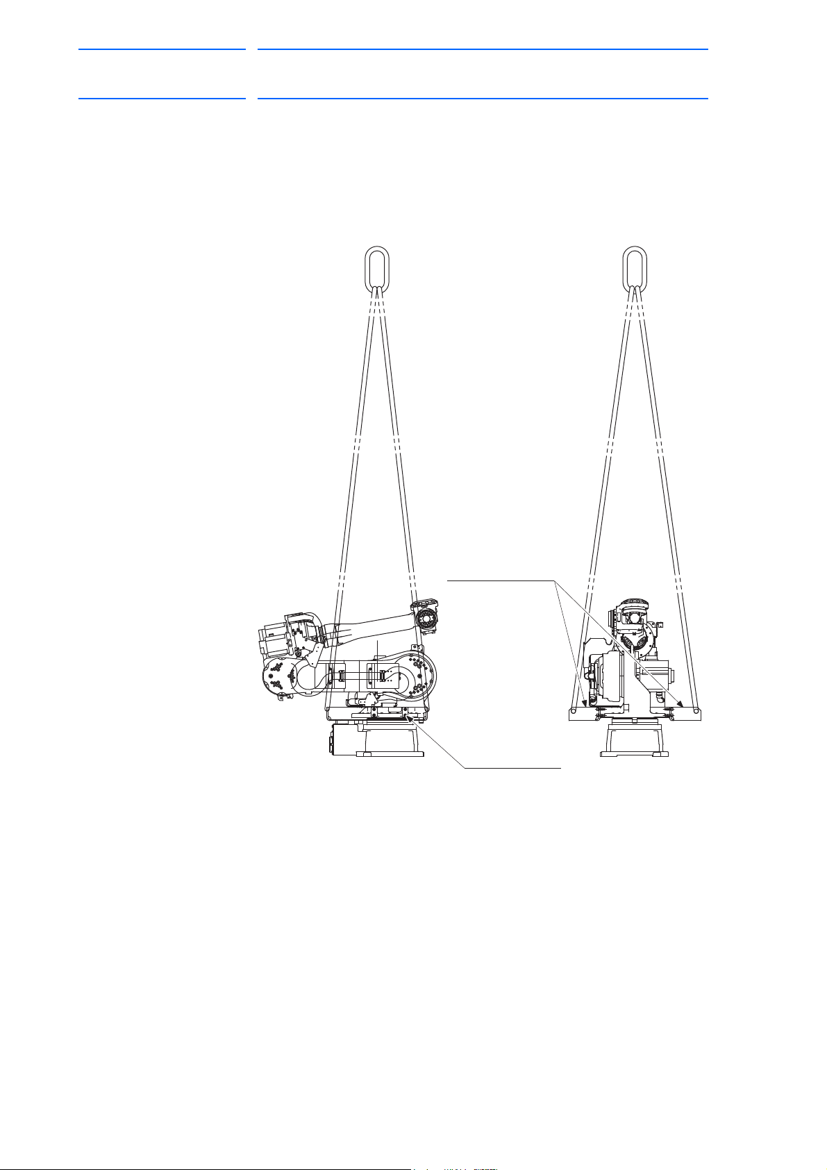
2.1.1 Using a Crane
As a rule, when uncrating the manipulator and moving it, a crane should
be used. Lift the manipulator with a four-leg bridle sling using the shipping
bolts and brackets. Be sure that the manipulator is fixed with the shipping
bolts and brackets before transport, and lift it in the posture as shown in
Fig. 2-1 “Transport Using a Crane”.
Fig. 2-1: Transport Using a Crane
2-2
HW1480080
Page 15

158813-1CD
Pallet
Shipping bolts and bracket
(Fixed to the manipulator
before shipment.)
Screw M20
(8 screws)
Forklift claw entries
15 of 77
MH80 Manipulator
2 Transport
2.1 Transporting Method
2.1.2 Using a Forklift
When using a forklift, the manipulator should be fixed on a pallet with
shipping bolts and brackets as shown in
Insert claws into the folklift claw entries of the pallet and lift it. The pallet
must be strong enough to support the manipulator.
Transport the manipulator slowly with due caution in order to avoid
overturn or slippage.
Fig. 2-2: Transport Using a Forklift
Fig. 2-2 “Transport Using a Forklift”.
2-3
HW1480080
Page 16

MH80 Manipulator
NOTE
16 of 77
158813-1CD
2 Transport
2.2 Shipping Bolts and Brackets
2.2 Shipping Bolts and Brackets
The manipulator is provided with shipping bolts and brackets at positions
as shown in the figures in section 2.1 “Transporting Method” on page 2-1,
to protect its driving units from various external force during transport.
The shipping brackets are painted yellow.
Before turning ON the power, check to be sure that the
shipping bolts and brackets have been removed. The
shipping bolts and brackets then must be stored for future
use, in the event that the manipulator must be moved again
for relocation.
2-4
HW1480080
Page 17

158813-1CD
WARNING
CAUTION
17 of 77
MH80 Manipulator
3 Installation
3 Installation
• Install the safeguarding.
Failure to observe this warning may result in injury or damage.
• Install the manipulator in a location where the manipulator’s tool or
the workpiece held by the manipulator will not reach the wall,
safeguarding, or DX100 when the arm is fully extended.
Failure to observe this warning may result in injury or damage.
• Do not start the manipulator or even turn ON the power before it is
firmly anchored.
The manipulator may overturn and cause injury or damage.
• Do not install or operate a manipulator that is damaged or lacks
parts.
Failure to observe this caution may cause injury or damage.
• Before turning ON the power, check to be sure that the shipping
bolts and brackets explained in section 2.2 “Shipping Bolts and
Brackets” on page 2-4 are removed.
Failure to observe this caution may result in damage to the driving
parts.
3-1
HW1480080
Page 18

MH80 Manipulator
18 of 77
158813-1CD
3 Installation
3.1 Installation of Safeguarding
3.1 Installation of Safeguarding
To insure safety, be sure to install the safeguarding. They prevent
unforeseen accidents with personnel and damage to equipment. The
following is quoted for your information and guidance.
Responsibility for Safeguarding (ISO 10218)
The user of a manipulator or robot system shall ensure that safeguarding
is provided and used in accordance with Sections 6, 7, and 8 of this
standard. The means and degree of safeguarding, including any
redundancies, shall correspond directly to the type and level of hazard
presented by the robot system consistent with the robot application.
Safeguarding may include but not be limited to safeguarding devices,
barriers, interlock barriers, perimeter guarding, awareness barriers, and
awareness signals.
3.2 Mounting Procedures for Manipulator Base
The manipulator should be firmly mounted on a baseplate or foundation
strong enough to support the manipulator and withstand repulsion forces
during acceleration and deceleration. Construct a solid foundation with
the appropriate thickness to withstand maximum repulsion force of the
manipulator. (Refer toTable 3-1 "Maximum Repulsion Force of the
Manipulator at Emergency Stop" andTable 3-2 "Endurance Torque in
Operation".)
A baseplate flatness must be kept at 0.5 mm or less: insufficient flatness
of installation surface may deform the manipulator shape and affect its
functional abilities.
For installation, refer to Fig. 3-1 “Mounting the Manipulator on the
Baseplate” or Fig. 3-2 “Mounting the Manipulator on the Floor”.
Table 3-1:
Maximum torque in horizontal rotation
(S-axis moving direction)
Maximum torque in vertical rotation
(LU-axis moving direction)
Maximum Repulsion Force of the Manipulator at Emergency Stop
24500 N·m
(2500 kgf·m)
45080 N·m
(4600 kgf·m)
Table 3-2: Endurance Torque in Operation
Endurance torque in horizontal operation
Endurance torque in vertical operation
6125N·m
(625 kgf·m)
11270 N·m
(1150 kgf·m)
3-2
HW1480080
Page 19

158813-1CD
Flatness: 0.5mm or less
Baseplate
Anchor bolt (M20 or more)
Manipulator base
Hexagon head screw
M20 (8 screws)
Spring washer
Washer
Baseplate
50 30
19 of 77
MH80 Manipulator
3 Installation
3.2 Mounting Procedures for Manipulator Base
3.2.1 Mounting the Manipulator on the Baseplate
The baseplate should be rugged and durable to withstand maximum
repulsion force of the manipulator and to ensure that the manipulator and
fixture are in the correct relative position. The thickness of the baseplate
is 50 mm or more and an M20 size or larger anchor bolt is recommended.
After anchoring the baseplate firmly on the floor, fix the manipulator base
to the baseplate with the hexagon head screw M20 (8 screws, length of
70 mm or more is recommended) using mounting holes on the
manipulator base. The manipulator base is tapped for eight mounting
holes. Tighten the hexagon head bolts and anchor bolts securely so that
they will not work loose during operation. For details, refer to Fig. 3-1
“Mounting the Manipulator on the Baseplate”.
Fig. 3-1: Mounting the Manipulator on the Baseplate
3-3
HW1480080
Page 20
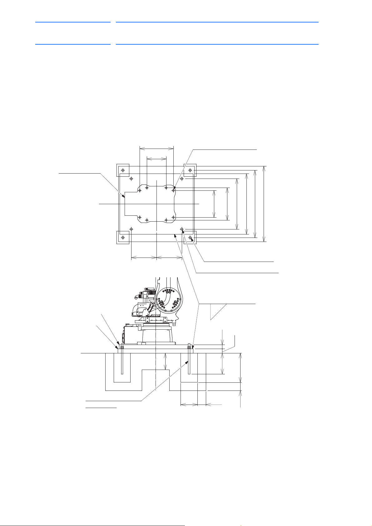
MH80 Manipulator
28 dia.hole (4 holes) (Base B)
28 dia.hole (4 holes) (Base A)
Base B
Base A
Level the floor.
JA-type anchor bolt M24
Weld here after installation
and adjustment .
Units: mm
Screw A: Screw M20 (length: 70) (8 screws); spring washer, flat washer
Screw B: Screw M24 (length: 70) (4 screws); spring washer
The fixing screws and bases are to be prepared by customer.
(length: 315)
Tapped hole M20 (8 holes);
Manipulator base
Tapped hole M24 (4 holes) (Base B);
Screw B
Screw A
600
900
800
720
385
320
300300
400
230
FL
32
36250
350
200
100
100
200
10
20 of 77
3 Installation
3.2 Mounting Procedures for Manipulator Base
3.2.2 Mounting the Manipulator on the Floor
The floor should be strong enough to support the manipulator. Construct
a solid foundation with the appropriate thickness to withstand maximum
repulsion force of the manipulator shown in Table 3-1 "Maximum
Repulsion Force of the Manipulator at Emergency Stop" . As a rough
standard, if there is a concrete thickness (floor) of 200 mm or more, the
manipulator base can be fixed directly to the floor with anchor bolts M20.
Before mounting the manipulator, however, check that the floor is level
and that all cracks, etc. are repaired. Any thickness less than 200 mm is
insufficient for mounting, even if the floor is concrete.
Fig. 3-2: Mounting the Manipulator on the Floor
158813-1CD
3-4
HW1480080
Page 21

158813-1CD
NOTE
Manipulator base
Support for fall prevention
Hexagon socket head cap
screw M20 (8 screws)
(Tensile strength: 1200 N/mm
2
or more)
21 of 77
MH80 Manipulator
3 Installation
3.3 Types of Mounting
3.3 Types of Mounting
The MOTOMAN-MH80 is available in three ways: floor-mounted
(standard), wall-mounted and ceiling-mounted way. For wall-mounted and
ceiling-mounted ways, the three points listed below are different from the
floor-mounted way.
• S-axis Operating Range
• Fixing the Manipulator Base
• Precautions to Prevent the Manipulator from Falling
3.3.1 S-axis Operating Range
For wall-mounted way, the S-axis operating range is ±30°.
(The range is adjusted prior to the shipment.)
3.3.2 Fixing the Manipulator Base
For wall- and ceiling-mounted ways, be sure to use eight hexagon socket
head cap screws M20 (tensile strength: 1200 N/mm
2
or more) when fixing
the manipulator base. Use a torque of 402 N•m (41 kgf•m) when
tightening the screws.
3.3.3 Precautions to Prevent the Manipulator from Falling
For the wall- or ceiling-mounted ways, take appropriate measures to avoid
the falling of the manipulator in case of emergency. Refer to Fig. 3-3
“Precaution Against Falling” for details.
Fig. 3-3: Precaution Against Falling
In case of using the wall-/ceiling-mounted way, inform
Yaskawa of the matter when placing an order. Be sure to
contact your Yaskawa representative (listed on the back
cover of this instruction manual) to perform a wall/ceiling
installation on site.
3-5
HW1480080
Page 22
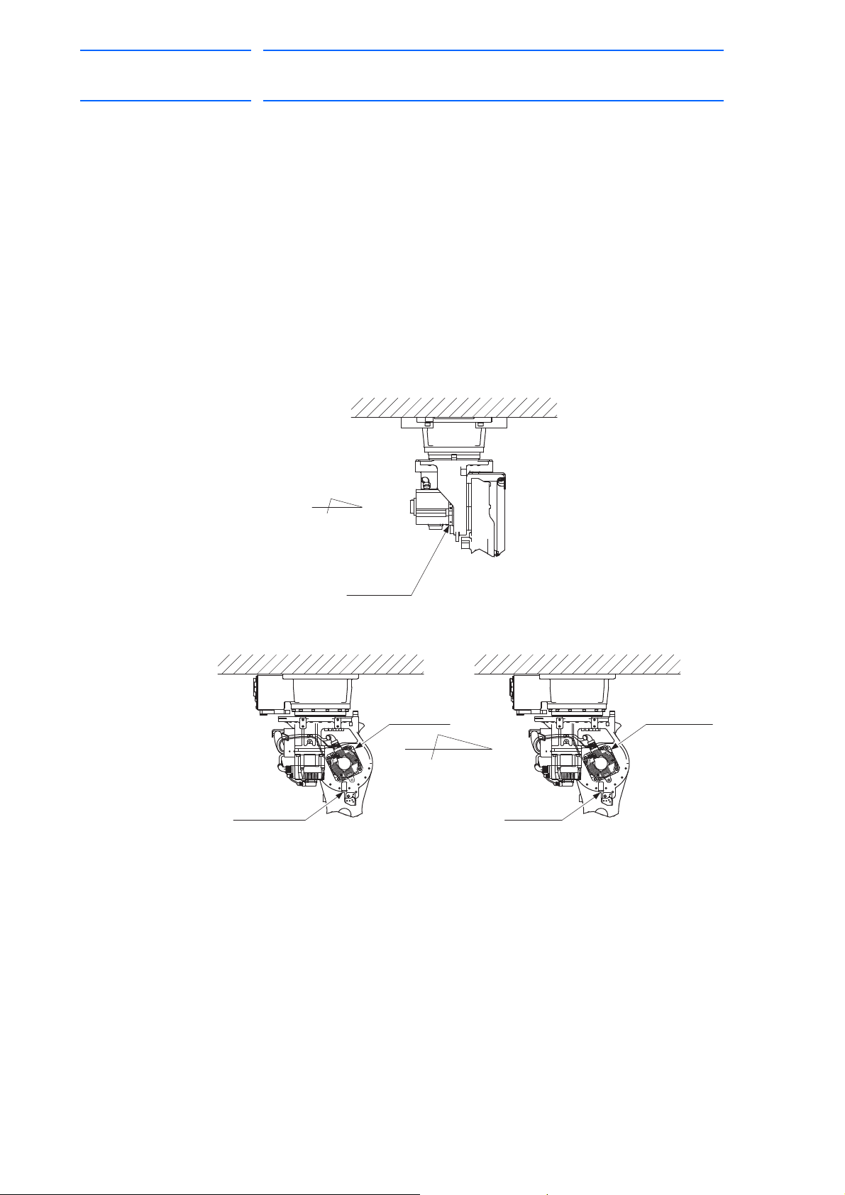
MH80 Manipulator
(After)
View A
(Before)
Air Breather
Air Breather
Grease Cap
Grease Cap
Motor base
A
22 of 77
158813-1CD
3 Installation
3.4 Notes in Mounting the Manipulators on the Ceiling
3.4 Notes in Mounting the Manipulators on the Ceiling
In the case if the manipulator shipped is the floor-mounted way, yet is to
be mounted on the ceiling, mounting positions of each part on the view A
in the figure below should be changed after installing the manipulator on
the ceiling, to prevent a grease leakage from an air breather.
Change the mounting positions of the parts as shown in the figure below.
After installing the manipulator on the ceiling, replace the positions of the
parts installed in the L-axes motor base, by switching the positions of the
grease cap and the air breather.
Replace the positions of the grease cap and the air breather promptly, to
prevent the grease leakage from a hole where a grease cap is to be
installed.
Fig. 3-4: Parts Positions for Ceiling Mounted Manipulator
3-6
HW1480080
Page 23

158813-1CD
NOTE
(After)
View A
(Before)
Air Breather
Grease Cap
Air Breather
Grease Cap
Motor base
Connector base
A
23 of 77
MH80 Manipulator
3 Installation
3.4 Notes in Mounting the Manipulators on the Ceiling
3.5 Notes in Mounting the Manipulators on the Wall
In the case if the manipulator shipped is the floor-mounted way, yet is to
be mounted on the wall, mounting positions of each part on the view A in
the figure below should be changed after installing the manipulator on the
wall, to prevent a grease leakage from an air breather.
Change the mounting positions of the parts as shown in the figure below.
After installing the manipulator on the wall, replace the positions of the
parts installed in the motor base, by switching the positions of the grease
cap and the air breather.
Replace the positions of the grease cap and the air breather promptly, to
prevent the grease leakage from a hole where a grease cap is to be
installed.
When used in the wall mounted position, install the
manipulator so that a connector base becomes the top.
Fig. 3-5: Parts Positions for Wall Mounted Manipulator
3-7
HW1480080
Page 24

MH80 Manipulator
24 of 77
3 Installation
3.6 IP (International Protection)
3.6 IP (International Protection)
For the standard type, environmental resistance for main part of the
manipulator conforms to IP54; the wrist part conforms to IP67.
However, for wall-mounted or ceiling mounted ways, environmental
resistance for main part of the manipulator does not conform to IP54;
environmental resistance for IP65 is optionally available.
3.7 Location
When installing the manipulator, satisfy the following environmental
conditions.
• Ambient temperature: 0° to 45°C
• Humidity: 20 to 80%RH at constant temperature
• Free from exposure to water, oil, or dust
• Free from corrosive gas or liquid, or explosive gas or liquid
• Free from excessive vibration (Vibration acceleration: 4.9 m/s
[0.5 G] or less)
158813-1CD
2
• Free from large electrical noise (plasma)
• Flatness for installation is 0.5 mm or less
3-8
HW1480080
Page 25

158813-1CD
WARNING
CAUTION
NOTE
5.5mm2 or more
Screw M8 (for grounding)
(Delivered with the manipulator)
View A
A
2
25 of 77
MH80 Manipulator
4Wiring
4 Wiring
4.1 Grounding
• Ground resistance must be 100Ω or less.
Failure to observe this warning may result in fire or electric shock.
• Before wiring, make sure to turn OFF the primary power supply, and
put up a warning sign. (ex. DO NOT TURN THE POWER ON.)
Failure to observe this warning may result in fire or electric shock.
• Wiring must be performed by authorized or certified personnel.
Failure to observe this caution may result in fire or electric shock.
4.1 Grounding
Follow local regulations for grounding line size. A line of 5.5 mm2 or more
is recommended. Refer to Fig. 4-1 “Grounding Method” to connect the
ground line directly to the manipulator.
Fig. 4-1: Grounding Method
• Do not use this line sharing with other ground lines or
grounding electrodes for other electric power, motor
power, welding devices, etc.
• Where metal ducts, metallic conduits, or distributing racks
are used for cable laying, ground in accordance with local
electric equipment technical standards.
4-1
HW1480080
Page 26

MH80 Manipulator
26 of 77
158813-1CD
4 Wiring
4.2 Manipulator Cable Connection
4.2 Manipulator Cable Connection
Two manipulator cables are delivered with the manipulator: an encoder
cable (1BC) and a power cable (2BC). Refer to Fig. 4-2 “Manipulator
Cables” on page 4-3. Connect these cables to the connectors on the
manipulator connector base and the DX100 board connectors.
4.2.1 Connection to the Manipulator
Before connecting the manipulator cables to the manipulator, verify the
connector numbers: both the cables and the connectors on the
manipulator base are marked with 1BC and 2BC. Connect the cables in
the order of 2BC, 1BC, referring to Fig. 4-3(a) "Manipulator Cable
Connection (To the Manipulator)" on page 4-4. When connecting, insert
each cable connector adjusting its position to the main keys on the
connector base of the manipulator, and then depress the lever until it
clicks.
4.2.2 Connection to the DX100
Before connecting the manipulator cables to the DX100, verify the
connector numbers: both the cables and the connectors on the DX100 are
marked with X11 and X21. Connect the cables in the order of X21, X11,
referring to Fig. 4-3(b) "Manipulator Cable Connection (To the DX100)" on
page 4-4. When connecting, insert each cable connector adjusting its
position to the main keys on the DX100, and then depress the lever until it
clicks.
4-2
HW1480080
Page 27

158813-1CD
2BC
1BC
Power Cable
DX100 Manipulator
DX100 Manipulator
Encoder Cable
X11
1BC
X21
2BC
X11
1BC
X21 2BC
27 of 77
MH80 Manipulator
4 Wiring
4.2 Manipulator Cable Connection
Fig. 4-2: Manipulator Cables
4-3
HW1480080
Page 28

MH80 Manipulator
AIR
1BC
2BC
AIR
1BC
2BC
X11
X21
28 of 77
158813-1CD
4 Wiring
4.2 Manipulator Cable Connection
Fig. 4-3(a): Manipulator Cable Connection (To the Manipulator)
Fig. 4-3(b): Manipulator Cable Connection (To the DX100)
4-4
HW1480080
Page 29

158813-1CD
29 of 77
MH80 Manipulator
5 Basic Specifications
5.1 Basic Specifications
5 Basic Specifications
5.1 Basic Specifications
Table 5-1: Basic Specifications
Item Model MOTOMAN-MH80
Configuration Vertically Articulated
Degree of Freedom 6
Payload 80 kg
Repeatability
Range of Motion
Maximum Speed S-axis 2.97 rad/s, 170°/s
Allowable Moment
Allowable Inertia (GD
Approx. Mass 555 kg
Ambient
Conditions
Power Capacity 4.5 kVA
1 Conformed to ISO9283
2 For the limit switch specification (type: MOTOMAN-MH00080-A01),
the range of motion is limited with limit switch before shipment.
3 Refer to Table 6-1 "Allowable Total Moment of Wrist" on page 6-1" for details
on the allowable moment of inertia.
Note: SI units are used in this table. However, gravitational unit is used in ().
1)
2)
3)
S-axis (turning) -180° - +180°
L-axis (lower arm) -90° - +135°
U-axis (upper arm) -170° - +251°
R-axis (wrist roll) -360° - +360°
B-axis (wrist pitch/yaw) -125° - +125°
T- axis (wrist twist) -360° - +360°
L-axis 2.44 rad/s, 140°/s
U-axis 2.79 rad/s, 160°/s
R-axis 4.01 rad/s, 230°/s
B-axis 4.01 rad/s, 230°/s
T-axis 6.11 rad/s, 350°/s
2.97 rad/s, 170°/s 392 N•m (40 kgf•m)
2.44 rad/s, 140°/s 392 N•m (40 kgf•m)
2.79 rad/s, 160°/s 196 N•m (20 kgf•m)
2
/4) R-Axis 28 kg•m
B-Axis 28 kg•m
T-Axis 11 kg•m
Temperature 0°C to 45°C
Humidity 20 to 80% RH at constant temperature
Vibration Acceleration Less than 4.9 m/s
Others Free from corrosive gas or liquid, or explosive gas.
±0.07 mm
2
2
2
2
(0.5G)
Free from water, oil, or dust.
Free from excessive electrical noise (plasma).
5-1
HW1480080
Page 30

MH80 Manipulator
(S-head)
Base
(U-arm)
Wrist flange
Wrist
S+
S-
L+L-
U-
U+
R+
R-
B-
B+
T+
T-
Rotary head
(L-arm)
Lower arm
Upper arm
22 dia. hole
(8 holes)
12 dia. hole
(2 holes)
+0.018
0
View A
30
A
153
455
608
455
±
0.1
195
385
320
±
0.1
195
±
0.1
195
±
0.1
230
±
0.1
195
400
230
230±
0.1
Manipulator Base Dimensions
30 of 77
158813-1CD
5 Basic Specifications
5.2 Part Names and Working Axes
5.2 Part Names and Working Axes
Fig. 5-1: Part Names and Working Axes
5.3 Manipulator Base Dimensions
Fig. 5-2: Manipulator Base Dimensions
5-2
HW1480080
Page 31

158813-1CD
P-point maximum
envelope
P-point
R377
234 234
40 223.5
57
55
°
90
°
135
°
3578
1751025145
3832
R2061
R543
120
°
1807
187540 870
210
343
265
105105
0
118
1369
453
170
°
0
437
925
2456
460
1121
0
2061
543
530
87
213
605
1056
1771
248
A
View A
31 of 77
MH80 Manipulator
5 Basic Specifications
5.4 Dimensions and P-Point Maximum Envelope
5.4 Dimensions and P-Point Maximum Envelope
Fig. 5-3: Dimensions and P-Point Maximum Envelope
5-3
HW1480080
Page 32

MH80 Manipulator
32 of 77
5 Basic Specifications
5.5 Alterable Operating Range
5.5 Alterable Operating Range
The operating range of the S-axis can be altered according to the
operating conditions as shown in Fig. 5-2 “S-Axis Operating Range”. If
alteration is necessary, contact your Yaskawa representative in advance.
Table 5-2: S-Axis Operating Range
Item Specifications
S-Axis Operating Range -180° - +180°
158813-1CD
(standard)
-165° - +165°
-150° - +150°
-135° - +135°
-120° - +120°
-105° - +105°
-90° - +90°
-75° - +75°
-60° - +60°
-45° - +45°
-30° - +30°
-15° - +15°
5-4
HW1480080
Page 33

158813-1CD
P-point
R-, T-axis center of rotation
B-axis center of rotation
LT(mm)
LT(mm)
600
400
200
400
200
400 800
LB(mm)
80kg
70kg
60kg
50kg
33 of 77
MH80 Manipulator
6 Allowable Load for Wrist Axis and Wrist Flange
6.1 Allowable Wrist Load
6 Allowable Load for Wrist Axis and Wrist Flange
6.1 Allowable Wrist Load
The allowable wrist load is 80 kg; however, consider the limitations shown
in Table 6-1 "Allowable Total Moment of Wrist" to fulfill this condition. If
force is applied to the wrist instead of the load, the forces on R-, B-, and TAxes should be within the values shown in Table 6-1.
Table 6-1: Allowable Total Moment of Wrist
Axis Moment N•m (kgf•m)
R-Axis 392 (40) 28
B-Axis 392 (40) 28
T-Axis 196 (20) 11
1 ( ): Gravitational unit
1)
2
/4 Total Moment of Inertia kg•m
GD
2
When the volume load is small, refer to the moment arm rating shown in
Fig. 6-1 “Moment Arm Rating”.
The allowable total inertia is calculated when the moment is at the
maximum. Contact your Yaskawa representative when only inertia, or
load moment is small and inertia is large. Also, when the load mass is
combined with an outside force, contact your Yaskawa representative.
Fig. 6-1: Moment Arm Rating
6-1
HW1480080
Page 34

MH80 Manipulator
P.C.D.80
42
40
6
6
10
Alignment mark
Units: mm
+0.015
0
8 dia. hole
(depth: 14)
+0.012
0
6 dia. hole
(depth: 10)
Tapped hole M8
(depth: 14) (pitch: 1.25) (6 holes)
0
-0.022
100 dia.
+0.025
0
50 dia. hole
NOTE
34 of 77
158813-1CD
6 Allowable Load for Wrist Axis and Wrist Flange
6.2 Wrist Flange
6.2 Wrist Flange
The wrist flange dimensions are shown in Fig. 6-2 “Wrist Flange”. To
make the alignment mark visible and to enable an easy grease exchange
for the B- and T-axis gears, mount the attachment inside the fitting. Fitting
depth of inside and outside fittings must be 5 mm or less.
Fig. 6-2: Wrist Flange
Wash off anti-corrosive paint (Yellow) on the wrist flange
surface with thinner or light oil before mounting the tools.
6-2
HW1480080
Page 35

158813-1CD
(pitch:1.25)(4 holes)
Tapped hole M8(depth:16)
(pitch:1.75)(4 holes)
Tapped hole M12(depth:18)
(pitch:1.25)(4 holes)
Tapped hole M8(depth:16)
Mount the peripheral
equipment within this range.
A
B
A
C
View A
Peripheral Equipment Mounuts and Tapped hole
10
57
187
22440
105105
200 513
100
50
100
180
60
100 98.5
50
50
60
60
35 of 77
MH80 Manipulator
7 System Application
7.1 Peripheral Equipment Mounts
7 System Application
7.1 Peripheral Equipment Mounts
The peripheral equipment mounts are fixed on the upper arm for easier
installation of the user's system application as shown in Fig. 7-1 “Installing
Peripheral Equipment”. Observe the conditions in the figure and table
below in mounting the peripheral equipment on the U-axis.
Fig. 7-1: Installing Peripheral Equipment
Table 7-1: Conditions for Installation
Section Application Note
A Cabling Up to 80 kg for attaching load
B Cabling
mass including wrist load.
Up to 10 kg.
N•m (5 kgf•m) max. for
49
Valve mounting
increased moment amount of
upper arm
C Transformer, etc. mounting 30 kg or less
7-1
HW1480080
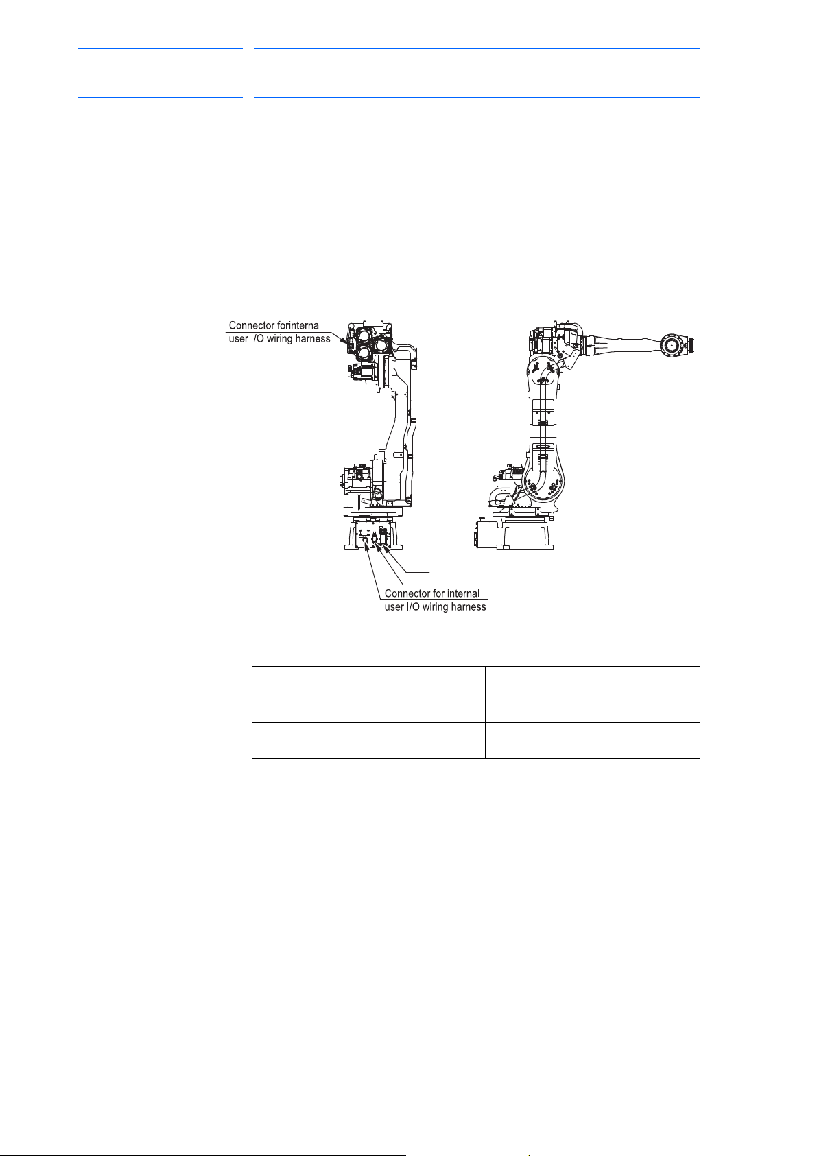
Page 36

MH80 Manipulator
AIR
1BC
2BC
A
B
Connector for internal user I/O wiring harness:
Prepare pin connector JL05-6A24-28P
JL05-2A24-28SC(socket connector with a cap)
Tapped hole PT3/8 with a pipe plug
Air inlet
Air inlet
Tapped hole PT3/8 with a pipe plug
View B
View A
Connector for internal user I/O wiring harness:
JL05-2A24-28PC(socket connector with a cap)
Prepare pin connector JL05-6A24-28S
Pin Details for Internal User I/O Wiring Harness
Pin Used
Internal user I/O wiring harness:
0.5mm
2
, 23 wires
8
4
9
6517
23
14
19
20
15
17
11 121813
21 22 23
10
16
P
P
P
P
P
P
P
P
P
P
P
1
6
5
3
4
2
7
8
9
10
15
14
13
12
11
20
19
17
18
16
22
23
21
36 of 77
7 System Application
7.2 Internal User I/O Wiring Harness and Air Lines
7.2 Internal User I/O Wiring Harness and Air Lines
Internal user I/O wiring harness (0.5 mm2 x 23 wires) and an air line are
incorporated in the manipulator for the drive of peripheral devices
mounted on the upper arm as shown in Fig. 7-2 “Connectors for Internal
User I/O Wiring Harness and Air Lines”
The Fig. 7-2 “Connectors for Internal User I/O Wiring Harness and Air
Lines” also shows the connector pin (1 to 23) assignment. Perform wiring
referring to the figure and the conditions below.
Items Conditions
The allowable current for internal user I/
O wiring harness
The maximum pressure for the air line 490 kPa (5 kgf/cm
Fig. 7-2: Connectors for Internal User I/O Wiring Harness and Air Lines
5.1A or less per a wire.
The total current value for pins 1 to 23
must be 34.5A or less.
(The air line inside diameter: 8 mm.)
2
) or less
158813-1CD
The same numbered pins (1 to 23) of the two connectors are connected
with a single lead wire of 0.5mm
2
.
7-2
HW1480080
Page 37

158813-1CD
NOTE
S-axis overrun limit switch
(For limit switch specification YR-MH00080-A01)
L-axis overrun limit switch
(For limit switch specification YR-MH00080-A01)
LU-axis interference limit switch
AIRAIR
1BC1BC
2BC2BC
37 of 77
MH80 Manipulator
8 Electrical Equipment Specification
8.1 Position of Limit Switch
8 Electrical Equipment Specification
8.1 Position of Limit Switch
8.1.1 Specification of Limit Switch
1. The interference limit switch at S-, L- and U-axes electrically limit the
operating range of respective axes by adjusting the position of the dog
using the limit switch.
The positions of the mechanical limits (mechanical stoppers) at S-, Land U-axes are changeable.
When the limit switch is activated, the power supply to the manipulator
is interrupted, then the manipulator makes an emergency stop as a
result. Refer to section 8.9 “Overrun/Tool Shock Sensor Releasing” in
“DX100 INSTRUCTIONS” for releasing the status of this overrun.
2. The range of S-, L- and U-axes limit switches are set to the maximum
operating range before shipping.
In case of re-adjusting the operating range of each subject
axis, it is also required to change the dog location and limit
values in software. Contact your Yaskawa representative if
re-adjustment is required.
Fig. 8-1: location of Limit Switches
8.1.2 Location of Limit Switches
Limit switches are optional. The limit switches (the S- and L-axis overrun
limit switches and the LU-axes interference limit switch) can be mounted
only if the manipulator type is YR-MH00080-A01. For each location, refer
to Fig. 8-1 “location of Limit Switches”.
8-1
HW1480080
Page 38

MH80 Manipulator
Negative side
Positive side
38 of 77
8.1.3 Setting of Operation Range
8.1.3.1 S-Axis Operation Range
8.1.3.2 L-Axis Operation Range
8 Electrical Equipment Specification
8.1 Position of Limit Switch
By the S-axis limit switch, S-axis operation range can be set to those
ranges mentioned in Table 5-2 "S-Axis Operating Range" on page 5-4.
By the L-axis limit switch, the L-axis operation range can be set to any
angles within -91° to +136° as mentioned in the figure below.
Fig. 8-2: L-Axis Overrun Limit Switch Setting Range
158813-1CD
8-2
HW1480080
Page 39

158813-1CD
39 of 77
MH80 Manipulator
8.1.3.3 Setting Range of LU-Axes Interference Angle
8 Electrical Equipment Specification
8.1 Position of Limit Switch
L- and U-axes interference limit switches are designed to check the
interference angle of L- and U-axes.
As shown in Fig. 8-3 “LU-Axes Interference Angle”, the operation range of
U-axis can be set to any angles within +9° to +297° as the interference
angle with L-axis.
Fig. 8-3: LU-Axes Interference Angle
8-3
HW1480080
Page 40
MH80 Manipulator
AIR
1BC
2BC
1BC
2BC
40 of 77
158813-1CD
8 Electrical Equipment Specification
8.2 Internal Connections
8.2 Internal Connections
Highly reliable connectors are equipped on each connection part of the
manipulator to enable easy removal and installation for maintenance and
inspection.
For the numbers, types, and locations of connectors, see Fig. 8-4
“Location of Connectors” and Fig. 8-1 “List of Connector Types”.
Diagrams for internal connections of the manipulator are shown in
Fig. 8-5(a) "Internal Connection Diagram" on page 8-5 and Fig. 8-5(b)
"Internal Connection Diagram" on page 8-6.
Fig. 8-4: Location of Connectors
Table 8-1: List of Connector Types
Name Type of Connector
Connector for internal user I/O wiring
harness on base connector
Connector for internal user I/O wiring
harness on U-arm
JL05-2A24-28PC
Prepare JL05-6A24-28S (optional)
JL05-2A24-28SC
Prepare JL05-6A24-28P (optional)
8-4
HW1480080
Page 41

158813-1CD
S-AXIS OVERRUN L.S. Connected to A1
SLU-axes with Limit Switch Specification
S-axis with Limit Switch Specification
L- AND U-AXES INTERFERENCE L.S. Connected to A3
L-AXIS OVERRUN L.S. Connected to A2
S-AXIS OVERRUN L.S. Connected to B1
L-AXIS OVERRUN L.S. Connected to B2
L AND U-AXES INTERFERENCE L.S. Connected to B3
S-AXIS OVERRUN L.S. Connected to B1
S-AXIS OVERRUN L.S. Connected to A1
<Notes>
1.For the limit switch specification, the connection of the section A B are changed as follows:
S-axis
L-axis
U-axis
R-axis
B-axis
T-axis
Lamp (option)
CASINGBASE
41 of 77
MH80 Manipulator
Fig. 8-5(a): Internal Connection Diagram
8 Electrical Equipment Specification
8.1 Internal Connections
8-5
HW1480080
Page 42

MH80 Manipulator
S-axis
L-axis
U-axis
R-axis
B-axis
T-axis
42 of 77
158813-1CD
8 Electrical Equipment Specification
8.1 Internal Connections
Fig. 8-5(b): Internal Connection Diagram
8-6
HW1480080
Page 43

158813-1CD
DANGER
WARNING
CAUTION
NOTE
43 of 77
MH80 Manipulator
9 Maintenance and Inspection
9.1 Inspection Schedule
9 Maintenance and Inspection
• Maintenance and inspection must be performed by specified
personnel.
Failure to observe this caution may result in electric shock or injury.
• For disassembly or repair, contact your Yaskawa representative.
• Do not remove the motor, and do not release the brake.
Failure to observe these safety precautions may result in death or
serious injury from unexpected turning of the manipulator's arm.
• Before maintenance or inspection, be sure to turn the main power
supply OFF, and put up a warning sign. (ex. DO NOT TURN THE
POWER ON.)
Failure to observe this warning may result in electric shock or injury.
• The battery pack must be connected before removing detection
connector when maintenance and inspection.
Failure to observe this caution may result in the loss of home position
data.
9.1 Inspection Schedule
Proper inspections are essential not only to assure that the mechanism
will be able to function for a long period, but also to prevent malfunctions
and assure safe operation. Inspection intervals are classified into six
levels as shown in Table 9-1 "Inspection Items" on page 9-2. Conduct
periodical inspections according to the inspection schedule in the table.
In Table 9-1 "Inspection Items" on page 9-2, the inspection items are
categorized by three types of operations: operations which can be
performed by personnel authorized by the user, operations which can be
performed by personnel being trained, and operations which can be
performed by service company personnel. Only specified personnel are
to do the inspection work.
• The inspection interval depends on the total servo
operation time.
• If axes are used very frequently (in handling applications,
etc.), inspections may be required at shorter intervals.
Contact your Yaskawa representative.
9-1
HW1480080
Page 44

Table 9-1: Inspection Items
44 of 77
1)
Items
1 Alignment marks
Schedule Method Operation Inspection
Charge
Daily
1000HCycle
6000HCycle
12000HCycle
24000HCycle
36000HCycle
••••••
Visual Check alignment mark accordance at the home position.
Check for damage.
Specified Personnel
Licensee
•••
MH80 Manipulator 9.1 Inspection Schedule
9 Maintenance and Inspection
Service Company
2 External cables
9-2
3 Working area
and whole exterior of
manipulator
4 SLURBT-axis motors
5 Baseplate mounting bolts
6 Cover mounting screws
HW1480080
7 SLURBT-axis motor
connectors
8 Connector base
••••••
••••••
••••••
••••••
••••••
••••••
••••••
Visual Check for damage and deterioration.
Visual Clean the work area if dust or spatter is present. Check for
damage and outside cracks.
Visual Check for grease leakage.
Wrench Tighten loose bolts. Replace if necessary.
Screwdriver,
Wrench
Manual Check for loose connectors and tighten if necessary.
Manual Check for loose connectors.
Tighten loose bolts. Replace if necessary.
2)
•••
•••
•••
•••
•••
•••
•••
158813-1CD
Page 45

Table 9-1: Inspection Items
45 of 77
1)
Items
Schedule Method Operation Inspection
Charge
158813-1CD
MH80 Manipulator 9.1 Inspection Schedule
9 Wire harness in manipulator
9-3
HW1480080
10 Limit switches and dogs
(For SLU-axes)
11 Battery pack in manipulator
12 S-axis speed reducer,
13 LU-axis speed reducers
Daily
1000HCycle
6000HCycle
12000HCycle
24000HCycle
36000HCycle
••••••
Visual,
Multimeter
Check for conduction between the main connector of base
and intermediate connector by manually shaking the wire.
Check for wear of protective spring.
3)
Specified Personnel
Licensee
Service Company
•••
•••••• • ••
••••••
••••••
••••••
••••••
Screwdriver,
Wrench,
Multimeter
Grease Gun Check for malfunction. (Replace if necessary.)
Grease Gun Check for malfunction. (Replace if necessary.)
Check for dirt, damage, malfunction.
Tighten loose bolts.
Replace the battery pack when the battery alarm occurs or
when the manipulator has been operated for 36000H.
4)
Supply grease 5) (6000H cycle).
Exchange grease 4) (12000H cycle).
See section 9.3.1 on page 9-8.
5)
Supply grease4) (6000H cycle).
Exchange grease4) (12000H cycle).
See section 9.3.2 on page 9-11 and
section 9.3.3 on page 9-13.
•••
•••
•••
•••
9 Maintenance and Inspection
Page 46

Table 9-1: Inspection Items
46 of 77
1)
Items
MH80 Manipulator 9.1 Inspection Schedule
Schedule Method Operation Inspection
Charge
14 R-axis speed reducer
15 BT-axis speed
reducers and gears
9-4
16 Overhaul
1 Inspection numbers correspond to the numbers in Fig. 9-1 “Inspection Parts and Inspection Numbers” on page 9-5.
2 The occurrence of a grease leakage indicates the possibility that grease has seeped into the motor. This can cause a motor
breakdown. Contact your Yaskawa representative.
3 When checking for conduction with multimeter, connect the battery to “BAT” and “OBT” of connectors on the motor side for each
axis, and then remove connectors on detector side for each axis from the motor. Otherwise, the home position may be lost. (Refer
HW1480080
to section 9.3.6 “Notes for Maintenance” on page 9-20)
4 For the grease, refer to Table 9-2 "Inspection Parts and Grease Used" on page 9-6.
5 The application that requires highly frequent operation such as handling may cause grease leakage of air breather or the internal
pressure rise of speed reducer. Contact your Yaskawa representative.
Daily
1000HCycle
6000HCycle
12000HCycle
24000HCycle
36000HCycle
••••••
••••••
Grease Gun Check for malfunction. (Replace if necessary.)
Supply grease4) (6000H cycle).
Exchange grease4) (12000H cycle).
See section 9.3.4 on page 9-16.
Grease Gun Check for malfunction. (Replace if necessary.)
Supply grease 4) (6000H cycle).
Exchange grease4) (12000H cycle).
See section 9.3.5 on page 9-18.
5)
5)
Specified Personnel
Licensee
Service Company
•••
•••
•••••• • ••
9 Maintenance and Inspection
158813-1CD
Page 47

158813-1CD
AIR
1BC
2BC
U-axis
1
6
13
6
11
9
7
7
14
15
6
6
6
4
12
5
10
8
6
2
6
13
L-axis
1
T-axis
B-axis
R-axis
S-axis
1
1
1
1
47 of 77
MH80 Manipulator
9 Maintenance and Inspection
9.1 Inspection Schedule
Fig. 9-1: Inspection Parts and Inspection Numbers
9-5
HW1480080
Page 48

MH80 Manipulator
Battery pack
Connector base
(length: 8mm) (4 screws)
Cross head APS bolt M6
Cross head APS bolt M4
(length: 12mm) (8 bolts)
(HW0470360-A)
AIR
1BC
2BC
(a) Back View
(b) Top View
48 of 77
158813-1CD
9 Maintenance and Inspection
9.2 Notes on Maintenance Procedures
Table 9-2: Inspection Parts and Grease Used
No. Grease Used Inspected Parts
13, 14, 15, 16 Molywhite RE No.00 Speed reducers for all axes
B-, T-axis gears
Inspection numbers correspond to the numbers in Fig. 9-1 “Inspection
Items” on page 9-2.
9.2 Notes on Maintenance Procedures
9.2.1 Battery Pack Replacement
The battery packs (type: HW0470360-A) are attached in the two locations
as shown in Fig. 9-2 “Battery Location”.
Fig. 9-2: Battery Location
9-6
HW1480080
Page 49

158813-1CD
Connector
Battery pack before replacement
See step 5 below.
See step 4 below.
New battery pack (HW0470360-A)
Circuit Board
(Type: SGDR-EFBA02A)
NOTE
NOTE
49 of 77
MH80 Manipulator
Fig. 9-3: Battery Connection
9 Maintenance and Inspection
9.2 Notes on Maintenance Procedures
1. Turn OFF the DX100 main power supply.
2. Remove the cover plate fastening screws M4 and from the connector
base and pull out the battery pack to replace with a new battery pack.
3. Remove the old battery pack from the battery holder.
4. Connect the new battery pack to the unoccupied connector on the
circuit boa
5. Remove the old battery pack from the circuit board.
6. Mount the new battery pack to the battery holder.
7. Reinstall the plate and fix it with the plate fastening screws M4.
rd.
Connect the new battery pack before removing the old one
so that the encoder absolute data does not disappear.
Be sure not to pinch the cable when putting the plate back
into place.
9-7
HW1480080
Page 50

MH80 Manipulator
NOTE
S-axis speed reducer
(Hexagon socket head plug PT1/4)
Grease inlet
(Hexagon socket head plug PT3/8)
Grease exhaust port
AIR
1BC
2BC
AIR
1BC
2BC
NOTE
50 of 77
158813-1CD
9 Maintenance and Inspection
9.3 Notes on Grease Replenishment/Exchange Procedures
9.3 Notes on Grease Replenishment/Exchange Procedures
Make sure to follow the instructions listed below at grease replenishment/
exchange. Failure to observe the following notes may result in damage to
motor and speed reducer.
• If grease is added without removing the plug/screw from
the grease exhaust port, grease will leak inside a motor or
an oil seal of a speed reducer will come off, which may
result in damage to the motor. Make sure to remove the
plug/screw.
• Do not install a joint, a hose, etc. to the grease exhaust
port. Failure to observe this instruction may result in
damage to the motor due to coming off of an oil seal.
• Make sure to use a grease pump to inject grease. Set air
supply pressure to the grease pump at 0.3 MPa or less,
and the grease injection rate at 8 g/s or less.
9.3.1 Grease Replenishment/Exchange for S-Axis Speed Reducer
Fig. 9-4: S-Axis Speed Reducer
• Make sure to fill hoses, which are joined to the grease
inlet, with grease beforehand to prevent air from intruding
into the speed reducer.
9.3.1.1 Grease Replenishment
(Refer to Fig. 9-4 “S-Axis Speed Reducer”.)
1. Remove the hexagon socket head plug PT1/8 from the grease
exhaust port.
• If grease is injected with the plug on, the grease will go
inside the motor and may cause a damage. Make sure to
remove the plug before the grease injection.
• Do not install a joint, a hose, etc. to the grease exhaust
port. Failure to observe this instruction may result in
damage to the motor due to coming off of an oil seal.
9-8
HW1480080
Page 51

158813-1CD
NOTE
51 of 77
MH80 Manipulator
9 Maintenance and Inspection
9.3 Notes on Grease Replenishment/Exchange Procedures
2. Remove the hexagon socket head plug PT1/4 from the grease inlet
and install the grease zerk PT1/4. (The grease zerk is delivered with
the manipulator.)
3. Inject grease into the grease inlet using a grease gun.
– Grease type: Molywhite RE No. 00
–
Amount of grease: 520 cc
(1040 cc for 1st supply)
– Air supply pressure of grease pump: 0.3 MPa or less
– Grease injection rate: 8 g/s or less
4. Move the S-axis for a few minutes to discharge excess grease.
5. Wipe the discharged grease with a cloth and reinstall the plug PT1/8
on
the grease exhaust port. Apply Three Bond 1206C to the thread
part of the plug, and tighten the plug with a tightening torque of 4.9
·m (0.5 kgf·m).
N
6. Remove the grease zerk from the grease inlet and reinstall the plug
PT1/4
. Apply Three Bond 1206C to the thread part of the plug, and
tighten the plug with a tightening torque of 12 N
·m (1.2 kgf·m).
9.3.1.2 Grease Exchange
r to Fig. 9-4 “S-Axis Speed Reducer”.)
(Refe
1. Remove the hexagon socket head plug PT1/8 from the grease
exhaust port.
• If grease is injected with the plug on, the grease will go
inside the motor and may cause a damage. Make sure to
remove the plug before the grease injection.
• Do not install a joint, a hose, etc. to the grease exhaust
port. Failure to observe this instruction may result in
damage to the motor due to coming off of an oil seal.
2. Remove the hexagon socket head plug PT1/4 from the grease inlet
an
d install the grease zerk PT1/4. (The grease zerk is delivered with
the manipulator.)
3. Inject grease into the grease inlet using a grease gun.
– Grease type: Molywhite RE No. 00
–
Amount of grease: 2600 cc
– Air supply pressure of grease pump: 0.3 MPa or less
– Grease injection rate: 8 g/s or less
4. The grease exchange is completed when new grease appears in the
exha
ust port. The new grease can be distinguished from the old
grease by color.
5. Move the S-axis for a few minutes to discharge excess grease.
9-9
HW1480080
Page 52

MH80 Manipulator
NOTE
52 of 77
158813-1CD
9 Maintenance and Inspection
9.3 Notes on Grease Replenishment/Exchange Procedures
6. Wipe the discharged grease with a cloth and reinstall the plug PT1/8
on the grease exhaust port. Apply Three Bond 1206C to the thread
part of the plug, and tighten the plug with a tightening torque of 4.9
N·m (0.5 kgf·m).
If the plug is installed while the grease is being exhausted,
the grease will go inside the motor and may cause a
damage. Ensure that the grease has been completely
exhausted before installing the plug.
7. Remove the grease zerk from the grease inlet and reinstall the plug
1/4.
PT
9-10
HW1480080
Page 53

158813-1CD
(Hexagon socket head plug PT3/8)
Grease exhaust port
L-axis speed reducer
(Hexagon socket head plug PT1/8)
Grease Inlet
NOTE
53 of 77
MH80 Manipulator
9.3.2 Grease Replenishment/Exchange for L-Axis Speed Reducer
Fig. 9-5: L-Axis Speed Reducer
9.3.2.1 Grease Replenishment
9 Maintenance and Inspection
9.3 Notes on Grease Replenishment/Exchange Procedures
(Refer to Fig. 9-5 “L-Axis Speed Reducer”.)
1. Tilt the L-arm vertical to the ground.
2. Remove the hexagon socket head plug PT1/8 from the grease
exhaust port.
• If grease is injected with the plug on, the grease will go
inside the motor and may cause a damage. Make sure to
remove the plug before the grease injection.
• Do not install a joint, a hose, etc. to the grease exhaust
port. Failure to observe this instruction may result in
damage to the motor due to coming off of an oil seal.
3. Remove the hexagon socket head plug PT1/8 from the grease inlet
d install the grease zerk PT1/8. (The grease zerk is delivered with
an
the manipulator.)
4. Inject grease into the grease inlet using a grease gun.
– Grease type: Molywhite RE No. 00
–
Amount of grease: 250 cc
(500 cc for 1st supply)
– Air supply pressure of grease pump: 0.3 MPa or less
– Grease injection rate: 8 g/s or less
5. Move the L-axis for a few minutes to discharge excess grease.
6. Wipe the discharged grease with a cloth and reinstall the plug PT1/8
on
the grease exhaust port. Apply Three Bond 1206C to the thread
part of the plug, and tighten the plug with a tightening torque of 4.9
·m (0.5 kgf·m).
N
7. Remove the grease zerk from the grease inlet and reinstall the plug
PT1/8
. Apply Three Bond 1206C to the thread part of the plug, and
tighten the plug with a tightening torque of 4.9 N
·m (0.5 kgf·m).
9-11
HW1480080
Page 54

MH80 Manipulator
NOTE
NOTE
54 of 77
9.3.2.2 Grease Exchange
158813-1CD
9 Maintenance and Inspection
9.3 Notes on Grease Replenishment/Exchange Procedures
(Refer to Fig. 9-5 “L-Axis Speed Reducer”.)
1. Tilt the L-arm vertical to the ground.
2. Remove the hexagon socket head plug PT1/8 from the grease
exhaust port..
• If grease is injected with the plug on, the grease will go
inside the motor and may cause a damage. Make sure to
remove the plug before the grease injection.
• Do not install a joint, a hose, etc. to the grease exhaust
port. Failure to observe this instruction may result in
damage to the motor due to coming off of an oil seal.
3. Remove the hexagon socket head plug PT1/8 from the grease inlet
nd install the grease zerk PT1/8. (The grease zerk is delivered with
a
the manipulator.)
4. Inject grease into the grease inlets using a grease gun.
– Grease type: Molywhite RE No. 00
–
Amount of grease: 1650 cc
– Air supply pressure of grease pump: 0.3 MPa or less
– Grease injection rate: 8 g/s or less
5. The grease exchange is completed when new grease appears in the
e
xhaust port. The new grease can be distinguished from the old
grease by color.
6. Move the L-axis for a few minutes t
7. Wipe the discharged grease with a clo
on the grease exhaust port. Apply Three Bond 1206C to the thread
part of the plug, and tighten the plug with a tightening torque of 4.9
·m (0.5 kgf·m).
N
If the plug is installed while the grease is being exhausted,
the grease will go inside the motor and may cause a
damage. Ensure that the grease has been completely
exhausted before installing the plug.
8. Remove the grease zerk from the grease inlet and reinstall the plug
1/8. Apply Three Bond 1206C to the thread part of the plug, and
PT
tighten the plug with a tightening torque of 4.9 N
o discharge excess grease.
th and reinstall the plug PT1/8
·m (0.5 kgf·m).
9-12
HW1480080
Page 55

158813-1CD
U-arm
(Hexagon socket head plug PT1/8)
(Hexagon socket head plug PT3/8)
Grease inlet
Grease exhaust port
U-axis speed reducer
NOTE
55 of 77
MH80 Manipulator
9.3.3 Grease Replenishment/Exchange for U-Axis Speed Reducer
Fig. 9-7: U-Axis Speed Reducer
9 Maintenance and Inspection
9.3 Notes on Grease Replenishment/Exchange Procedures
Fig. 9-6: U-Arm Posture in Grease Replenishment/Exchange for U-Axis
Speed Reducer
9.3.3.1 Grease Replenishment
(Refer to Fig. 9-7 “U-Axis Speed Reducer”.)
1. Tilt the U-arm horizontal to the ground. (Refer to Fig. 9-6 “U-Arm
Posture in Grease Replenishment/Exchange for U-Axis Speed
Reducer”.)
2. Remove the hexagon socket head plug PT1/8 from the grease
exhaust port.
3. Remove the hexagon socket head plug PT1/8 from the grease inlet
an
the manipulator.)
• If grease is injected with the plug on, the grease will go
inside the motor and may cause a damage. Make sure to
remove the plug before the grease injection.
• Do not install a joint, a hose, etc. to the grease exhaust
port. Failure to observe this instruction may result in
damage to the motor due to coming off of an oil seal.
d install the grease zerk PT1/8. (The grease zerk is delivered with
9-13
HW1480080
Page 56

MH80 Manipulator
NOTE
56 of 77
158813-1CD
9 Maintenance and Inspection
9.3 Notes on Grease Replenishment/Exchange Procedures
4. Inject grease into the grease inlet using a grease gun.
– Grease type: Molywhite RE No. 00
–
Amount of grease: 140 cc
(280 cc for 1st supply)
– Air supply pressure of grease pump: 0.3 MPa or less
– Grease injection rate: 8 g/s or less
5. Move the U-axis for a few minutes to discharge excess grease.
9.3.3.2 Grease Exchange
6. Wipe the discharged grease with a clo
on the grease exhaust port. Apply Three Bond 1206C to the thread
part of the plug, and tighten the plug with a tightening torque of
·m (0.5 kgf·m).
4.9 N
7. Remove the grease zerk from the grease inlet and reinstall the plug
PT
1/8. Apply Three Bond 1206C to the thread part of the plug, and
tighten the plug with a tightening torque of 4.9 N
Refer to Fig. 9-7 “U-Axis Speed Reducer”.)
(
1. Tilt the U-arm horizontal to the ground. (Refer to Fig. 9-6 “U-Arm
Posture in Grease Replenishment/Exchange for U-Axis Speed
Reducer”.)
2. Remove the hexagon socket head plug PT1/8 from the grease
ex
haust port.
• If grease is injected with the plug on, the grease will go
inside the motor and may cause a damage. Make sure to
remove the plug before the grease injection.
• Do not install a joint, a hose, etc. to the grease exhaust
port. Failure to observe this instruction may result in
damage to the motor due to coming off of an oil seal.
th and reinstall the plug PT1/8
·m (0.5 kgf·m).
3. Remove the hexagon socket head plug PT1/8 from the grease inlet
nd install the grease zerk PT1/8. (The grease zerk is delivered with
a
the manipulator.)
4. Inject grease into the grease inlet using a grease gun.
– Grease type: Molywhite RE No. 00
–
Amount of grease: 700 cc
– Air supply pressure of grease pump: 0.3 MPa or less
– Grease injection rate: 8 g/s or less
5. The grease exchange is completed when new grease appears in the
g
rease exhaust port. The new grease can be distinguished from the
old grease by color.
6. Move the U-axis for a few minutes to discharge excess grease.
9-14
HW1480080
Page 57

158813-1CD
NOTE
57 of 77
MH80 Manipulator
9 Maintenance and Inspection
9.3 Notes on Grease Replenishment/Exchange Procedures
7. Wipe the discharged grease with a cloth and reinstall the plug PT1/8
on the grease exhaust port. Apply Three Bond 1206C to the thread
part of the plug, and tighten the plug with a tightening torque of
·m (0.5 kgf·m).
4.9 N
If the plug is installed while the grease is being exhausted,
the grease will go inside the motor and may cause a
damage. Ensure that the grease has been completely
exhausted before installing the plug.
8. Remove the grease zerk from the grease inlet and reinstall the plug
. Apply Three Bond 1206C to the thread part of the plug, and
PT1/8
tighten the plug with a tightening torque of 4.9 N
·m (0.5 kgf·m).
9-15
HW1480080
Page 58

MH80 Manipulator
R-axis speed reducer
(Hexagon socket head plug PT3/8)
(Hexagon socket head plug PT1/8)
Grease exhaust port
Grease inlet
U-arm
NOTE
58 of 77
9.3.4 Grease Replenishment/Exchange for R-Axis Speed Reducer
9.3.4.1 Grease Replenishment
9 Maintenance and Inspection
9.3 Notes on Grease Replenishment/Exchange Procedures
Fig. 9-8: R-Axis Speed Reducer
158813-1CD
(Refer to Fig. 9-8 “R-Axis Speed Reducer”.)
1. Remove the hexagon socket head plug 1/8 from the grease exhaust
port.
• If grease is injected with the plug on, the grease will go
inside the motor and may cause a damage. Make sure to
remove the plug before the grease injection.
• Do not install a joint, a hose, etc. to the grease exhaust
port. Failure to observe this instruction may result in
damage to the motor due to coming off of an oil seal.
2. Remove the hexagon socket head plug PT1/8 from the grease inlet
and install the grease zerk PT1/8. (The grease zerk is delivered with
the manipulator.)
3. Inject grease into the grease inlet using a grease gun.
– Grease type: Molywhite RE No. 00
–
Amount of grease: 700 cc
(1400 cc for 1st supply)
– Air supply pressure of grease pump: 0.3 MPa or less
– Grease injection rate: 8 g/s or less
4. Move the R-axis for a few minutes to discharge excess grease.
5. Wipe the discharged grease with a clo
on the grease exhaust port. Apply Three Bond 1206C to the thread
part of the plug, and tighten the plug with a tightening torque of 4.9
N·m (0.5 kgf·m).
6. Remove the grease zerk from the grease inlet and reinstall the plug
1/8. Apply Three Bond 1206C to the thread part of the plug, and
PT
tighten the plug with a tightening torque of 4.9 N·m (0.5 kgf·m).
9-16
th and reinstall the plug PT1/8
HW1480080
Page 59

158813-1CD
NOTE
NOTE
59 of 77
MH80 Manipulator
9.3.4.2 Grease Exchange
9 Maintenance and Inspection
9.3 Notes on Grease Replenishment/Exchange Procedures
(Refer to Fig. 9-8 “R-Axis Speed Reducer”
1. Remove the hexagon socket head plug PT1/8 from the grease
exhaust port.
• If grease is injected with the plug on, the grease will go
inside the motor and may cause a damage. Make sure to
remove the plug before the grease injection.
• Do not install a joint, a hose, etc. to the grease exhaust
port. Failure to observe this instruction may result in
damage to the motor due to coming off of an oil seal.
2. Remove the hexagon socket head plug PT1/8 from the grease inlet
and install the grease zerk PT1/8. (The grease zerk is delivered with
the manipulator.)
3. Inject grease into the grease inlet using a grease gun.
– Grease type: Molywhite RE No. 00
–
Amount of grease: 3500 cc
– Air supply pressure of grease pump: 0.3 MPa or less
– Grease injection rate: 8 g/s or less
4. The grease exchange is completed when new grease appears from
the g
rease exhaust port. The new grease is distinguished from the old
grease by color.
5. Move the R-axis for a few minutes to discharge excess grease.
6. Wipe the discharged grease with a cloth and reinstall the plug PT1/8
on
the grease exhaust port. Apply Three Bond 1206C to the thread
part of the plug, and tighten the plug with a tightening torque of 4.9
N·m (0.5 kgf·m).
If the plug is installed while the grease is being exhausted,
the grease will go inside the motor and may cause a
damage. Ensure that the grease has been completely
exhausted before installing the plug.
7. Remove the grease zerk from the grease inlet and reinstall the plug
. Apply Three Bond 1206C to the thread part of the plug, and
PT1/8
tighten the plug with a tightening torque of 4.9 N·m (0.5 kgf·m).
9-17
HW1480080
Page 60

MH80 Manipulator
B-axis speed reducer and gear
T-axis speed reducer and gear
(Hexagon socket head plug PT1/8)
(Hexagon socket head plug PT1/8)
Grease exhaust port
Grease inlet
NOTE
60 of 77
9.3.5 Grease Replenishment/Exchange for B- and T-Axis Speed Reducers
9.3.5.1 Grease Replenishment
9 Maintenance and Inspection
9.3 Notes on Grease Replenishment/Exchange Procedures
and Gears
Fig. 9-9: B- and T-Axis Speed Reducers and Gears
(Refer to Fig. 9-9 “B- and T-Axis Speed Reducers and Gears”.)
158813-1CD
1. Remove the hexagon socket head set screw M6 from the grease
exhaust port.
• If grease is injected with the set screw on, the grease will
go inside the motor and may cause a damage. Make sure
to remove the plug before the grease injection.
• Do not install a joint, a hose, etc. to the grease exhaust
port. Failure to observe this instruction may result in
damage to the motor due to coming off of an oil seal.
2. Remove the hexagon socket head plug PT1/8 from the grease inlet
and install the grease zerk PT1/8. (The grease zerk is delivered with
the manipulator.)
3. Inject grease into the grease inlet using a grease gun.
– Grease type: Molywhite RE No. 00
–
Amount of grease: 300 cc
(600 cc for 1st supply)
– Air supply pressure of grease pump: 0.3 MPa or less
– Grease injection rate: 8 g/s or less
4. Move the B-axis for a few minutes to discharge excess grease.
5. Wipe the discharged grease with a cloth and reinstall the set screw M6
o
n the grease exhaust port. Apply Three Bond 1206C to the thread
part of the set screw, and tighten the set screw with a tightening torque
of 3.9 N·m (0.4 kgf·m).
6. Remove the grease zerk from the grease inlet and reinstall the plug
1/8. Apply Three Bond 1206C to the thread part of the plug, and
PT
tighten the plug with a tightening torque of 4.9 N·m (0.5 kgf·m).
9-18
HW1480080
Page 61

158813-1CD
NOTE
NOTE
61 of 77
MH80 Manipulator
9.3.5.2 Grease Exchange
9 Maintenance and Inspection
9.3 Notes on Grease Replenishment/Exchange Procedures
(Refer to Fig. 9-9 “B- and T-Axis Speed Reducers and Gears”.)
1. Remove the hexagon socket head set screw M6 from the grease
exhaust port.
• If grease is injected with the set screw on, the grease will
go inside the motor and may cause a damage. Make sure
to remove the plug before the grease injection.
• Do not install a joint, a hose, etc. to the grease exhaust
port. Failure to observe this instruction may result in
damage to the motor due to coming off of an oil seal.
2. Remove the hexagon socket head plug PT1/8 from the grease inlet
and install the grease zerk PT1/8. (The grease zerk is delivered with
the manipulator.)
3. Inject grease into the grease inlet using a grease gun.
– Grease type: Molywhite RE No. 00
–
Amount of grease: 1500 cc
– Air supply pressure of grease pump: 0.3 MPa or less
– Grease injection rate: 8 g/s or less
4. The grease exchange is completed when new grease appears from
the g
rease exhaust port. The new grease is distinguished from the old
grease by color.
5. Move the B-axis for a few minutes to discharge excess grease.
6. Wipe the discharged grease with a cloth and reinstall the set screw M6
on
the grease exhaust port. Apply Three Bond 1206C to the thread
part of the set screw, and tighten the set screw with a tightening torque
of 3.9 N·m (0.4 kgf·m).
If the plug is installed while the grease is being exhausted,
the grease will go inside the motor and may cause a
damage. Ensure that the grease has been completely
exhausted before installing the plug.
7. Remove the grease zerk from the grease inlet and reinstall the plug
. Apply Three Bond 1206C to the thread part of the plug, and
PT1/8
tighten the plug with a tightening torque of 4.9 N·m (0.5 kgf·m).
9-19
HW1480080
Page 62

MH80 Manipulator
NOTE
NOTE
b
a
a
b
0BT
BAT
BAT*
0BT*
Motor
Connector for battery backup
HW9470932-A (Battery pack)
Motor power connector
Connector for the motor encoder
a: Crimped contact-pin (pin)
b: Crimped contact-pin (socket)
62 of 77
9 Maintenance and Inspection
9.3 Notes on Grease Replenishment/Exchange Procedures
9.3.6 Notes for Maintenance
When performing maintenance such as replacement of a
wire harness in the manipulator, the encoder connector may
be necessary to be removed. In this case, be sure to
connect the battery pack to the battery backup connector
before removing the encoder connector.
Removing the encoder connector without connecting the
battery pack leads to disappearance of the encoder
absolute data.
For the battery pack connection, refer to Fig. 9-10 “Battery
Pack Connection for Motors”.
9.3.6.1 Battery Pack Connection for Motors
The connectors (crimped contact-pin) for battery backup are installed at
the end point of each motor (marked as BAT and OBT). Connect the
battery pack according to the following procedure.
158813-1CD
1. Remove a cap attached to battery backup connectors of the motor.
2. Connect a battery pack (HW9470932-A) to the battery backup
connectors (BAT and OBT are marked) located at the end point of an
encoder cable. With the battery pack connected to the battery backup
connectors, perform maintenance check.
3. After the maintenance check, confir
m all connectors are connected
and remove the battery pack. Reinstall the cap onto the battery
backup connectors of the motor.
Do not remove battery pack in the connector base.
Fig. 9-10: Battery Pack Connection for Motors
9-20
HW1480080
Page 63

158813-1CD
NOTE
63 of 77
MH80 Manipulator
10 Recommended Spare Parts
10 Recommended Spare Parts
It is recommended to keep the parts and components in the following table
in stock as spare parts for the MOTOMAN-MH80. Product performance
can not be guaranteed when using spare parts from any company other
than Yaskawa. The spare parts are ranked as follows:
• Rank A: Expendable and frequently replaced parts
• Rank B: Parts for which replacement may be necessary as a result of
frequent operation
• Rank C: Drive Unit
To replace parts in Rank B or Rank C, contact your
Yaskawa representative.
Table 10-1: Spare Parts for the MOTOMAN-MH80 (Sheet 1 of 2)
Rank Parts
A 1 Grease Molywhite RE No. 00 Yaskawa 16 kg - For all axis
A 2 Liquid Gasket Three Bond 1206C ThreeBond Co.,
A 3 Battery Pack HW9470932-A Yaskawa 1 1 For replacing
A 4 Battery Pack HW0470360-A Yaskawa 1 1
B5S-axis
B 6 S-axis Input Gear HW0313741-1 Yaskawa 1 1
B7L-axis
B 8 L-axis Input Gear HW0409103-1 Yaskawa 1 1
B9U-axis
B 10 U-axis Input Gear HW0313740-1 Yaskawa 1 1
B 11 R-axis
B 12 B-axis
B13T-axis
C 14 AC Servomotor
Name Type Manufacturer Qty Qty
No.
Ltd.
HW0387752-A Yaskawa 1 1
Speed Reducer
Speed Reducer
Speed Reducer
Speed Reducer
Speed Reducer
Speed Reducer
for S-axis
HW1382898-A Yaskawa 1 1 For the
HW9381465-A Yaskawa 1 1
HW0387753-A Yaskawa 1 1
HW0387754-A Yaskawa 1 1
HW0387737-B Yaskawa 1 1
HW0389043-A Yaskawa 1 1
SGMRV-30ANA-YR1*
HW0388669-A
Yaskawa 1 1
Remarks
per
Unit
speed reducers
and wrist units
--
the wire harness
in the
manipulator
manipulator
assembled after
Apr.2, 2014
10-1
HW1480080
Page 64

MH80 Manipulator
64 of 77
10 Recommended Spare Parts
Table 10-1: Spare Parts for the MOTOMAN-MH80 (Sheet 2 of 2)
158813-1CD
Rank Parts
C 15 AC Servomotor
C 16 AC Servomotor
C 17 AC Servomotors
C 18 Wire Harness in
C 19 Connector base
C 20 Limit switch set
C 21 Limit switch set
C 22 Limit switch set
C 23 Circuit Board SGDR-EFBA02A Yaskawa 1 1
Name Type Manufacturer Qty Qty
No.
for L-axis
for U-axis
for R-, B-, and Taxes
Manipulator
Unit
for S-axis
for L-axis
for U-axis
SGMRV-44ANA-YR2*
HW0388671-A
SGMRV-20ANA-YR1*
HW0388668-A
SGMRV-09ANA-YR1*
HW0388665-A
HW0174688-A Yaskawa 1 1
HW0374034-B Yaskawa 1 1
HW0472853-B Yaskawa 1 1 Treatment of
HW0472854-A Yaskawa 1 1 Treatment of
HW0472854-B Yaskawa 1 1 Treatment of
Yaskawa 1 1
Yaskawa 1 1
Yaskawa 1 3
Remarks
per
Unit
-A01 lead
terminal is done
-A01 lead
terminal is done
-A01 lead
terminal is done
10-2
HW1480080
Page 65

158813-1CD
1019
1001
1002
1003
1004
1005
1007
1009
1008
1010
1011
1013
1014
1016
1018
1020
1017
1021
1022
1025
1026
1028
1023
1024
1012
1030
1033
1029
1032
1031
1034
65 of 77
MH80 Manipulator
11 Parts List
Fig. 11-1: S-Axis Unit
11 Parts List
11.1 S-Axis Unit
11.1 S-Axis Unit
11-1
HW1480080
Page 66

MH80 Manipulator
66 of 77
158813-1CD
11 Parts List
11.1 S-Axis Unit
Table 11-1: S-Axis Unit
No. DWG No. Name Pcs
1001 HW0387752-A Speed reducer 1
HW1382898-A
(For the manipulator assembled
after Apr.2, 2014)
1002 SGMRV-30ANA-YR1* Motor 1
1003 HW9404486-1 Shaft 1
1004 HW0400405-1 Stopper 1
1005 6310 Bearing 1
1007 M8X45 Socket screw 1
1008 2H-8 Spring washer 1
1009 HW0102237-2 S head 1
1010 M12X45 Socket screw 15
M12X45
(For the manipulator assembled
after Apr.2, 2014)
1011 2H-12 Spring washer 15
2H-12
(For the manipulator assembled
after Apr.2, 2014)
1012 C-30-SG-22A Glomet 1
1013 M12X55 Socket screw 3
1014 2H-12 Spring washer 3
1016 STW-50 Retaining Ring-C
1017 M8X100 Socket screw 1
1018 2H-8 Spring washer 1
1019 PT3/8
(STAINLESS coating)
1020 MSTH10-25 Parallel pin 1
1021 M12X55 Socket screw 12
1022 2H-12 Spring washer 12
1023 HW9405875-1 Coller 1
1024 M20X40 Socket screw 1
1025 HW0102236-1 Base 1
1026 KQ2L10-01S Elbow 1
1028 NB-1075-0.43 Tube 1
1029 HW0314010-1 M base 1
1030 Y507212.5 Oil seal 1
1031 M6X20 Socket screw 2
1032 2H-6 Spring washer 2
1033 HW0313741-1 Gear 1
1034 M12X35
(For the manipulator assembled
after Apr.2, 2014)
Speed reducer 1
Socket screw 16
Spring washer 16
1
type
Plug 1
GT-SAbolt 2
11-2
HW1480080
Page 67

158813-1CD
2002
2005
2016
2004
2003
2026
2009
2008
2006
2007
2026
2027
2027
2027
2017
2011
2013
2014
2010
2019
2020
1009
2001
2021
2022
2024
2023
2018
2012
2025
2025
67 of 77
MH80 Manipulator
11 Parts List
11.2 L-Axis Unit
11.2 L-Axis Unit
Fig. 11-2: L-Axis Unit
11-3
HW1480080
Page 68

MH80 Manipulator
68 of 77
11 Parts List
11.2 L-Axis Unit
Table 11-2: L-Axis Unit
No. DWG No. Name Pcs
2001 SGMRV-44ANA-YR2* Motor 1
2002 HW0102644-1 L arm 1
2003 M12X55 Socket screw 16
2004 2H-12 Spring washer 16
2005 HW9381465-A Speed reducer 1
2006 M10X40 Socket screw 18
2007 2H-10 Spring washer 18
2008 M16X45 Socket screw 6
2009 2H-16 Spring washer 6
2010 HW9481343-A Shaft 1
2011 HW0409103-1 Gear 1
2013 HW0483473-B Socket screw 1
2014 HW0408806-2 Spring washer 1
2016 G270 O ring 1
2017 EZ0094-A0 Air breather 1
2018 HW0314011-1 M base 1
2019 HW0312815-2 Shaft 1
2020 Y507212.5 Oil seal 1
2021 M12X65 Socket screw 4
2022 2H-12 Spring washer 4
2023 M6X30 Socket screw 2
2024 2H-6 Spring washer 2
2025 EZ5002A0 Cap 3
2026 PT3/8
(STAINLESS coating)
2027 PT1/8
(STAINLESS coating)
1009 HW0102237-2 S head 1
Plug 2
Plug 4
158813-1CD
11-4
HW1480080
Page 69

158813-1CD
2002
3014
3015
3028
3023
3024
3007
3027
3017
3022
3001
3016
3021
3026
3025
3018
3008
3011
3010
3005
3006
3020
3019
3002
3004
3003
3012
3013
69 of 77
MH80 Manipulator
11 Parts List
11.3 U-Axis Unit
11.3 U-Axis Unit
Fig. 11-3: U-Axis Unit
11-5
HW1480080
Page 70

MH80 Manipulator
70 of 77
158813-1CD
11 Parts List
11.3 U-Axis Unit
Table 11-3: U-Axis Unit
No. DWG No. Name Pcs
3001 SGMRV-20ANA-YR1* Motor 1
3002 HW0413914-1 Stopper 1
3003 M6X55 Socket screw 1
3004 2H-6 Spring washer 1
3005 M8X55 Socket screw 4
3006 2H-8 Spring washer 4
3007 HW0387753-A Speed reducer 1
3008 HW0313740-1 Gear 1
3010 M8X115 Socket screw 1
3011 2H-8 Spring washer 1
3012 M12X30 Socket screw 12
3013 SW-2H-12 Washer 12
3014 M10X30 Socket screw 6
3015 2H-10 Spring washer 6
3016 HW9405257-1 Collar 1
3017 HW0102239-2 Casing 1
3018 Y426012.5 Oil seal 1
3019 M6X30 Socket screw 2
3020 2H-6 Spring washer 2
3021 HW0314012-1 M base 1
3022 G195 O ring 1
3023 M10X40 Socket screw 16
3024 2H-10 Spring washer 16
3025 TSH6-01M Union 2
3026 UB-0640-0.1C Tube 2
3027 PT1/8
(STAINLESS coating)
2028 PT3/8
(STAINLESS coating)
2002 HW0102425-1 L arm 1
Plug 1
Plug 1
11-6
HW1480080
Page 71

158813-1CD
4029
4030
4001
R axis
B axis
T axis
4003
4004
4005
4006
4007
4008
4009
4010
4011
4012
4013
4014
4015
4016
4017
4018
4019
4021
4022
4023
4024
4025
4026
4027
4028
4031
4031
4031
4033
4035
4034
4048
4036
4037
4037
4039
4038
4040
4041
4043
4042
4044
4046
4047
4049
4050
4045
3017
4007
4031
4020
4002
4046
4047
4046
4047
4002
4002
4049
4050
71 of 77
MH80 Manipulator
11.4 R-, B-, T-Axis Unit
Fig. 11-4: R-, B-, T-Axis Unit
11 Parts List
11.4 R-, B-, T-Axis Unit
11-7
HW1480080
Page 72

MH80 Manipulator
72 of 77
158813-1CD
11 Parts List
11.4 R-, B-, T-Axis Unit
Table 11-4: R-, B-, T-Axis Unit
No. DWG No. Name Pcs
4001 HW0387754-A Speed reducer 1
4002 SGMRV-09ANA-YR1* Motor 3
4003 AC1306-G00X6 Oil seal 1
4004 AE1017Q0 Oil seal 1
4005 ISTW-17 Retaining Ring 1
4006 HR32913J Bearing 1
4007 HR32005XJ Bearing 2
4008 HR32909J Bearing 1
4009 6003 Bearing 1
4010 HW0312823-1 Gear 1
4011 HW0312822-1 Gear 1
4012 HW0312824-1 Gear 1
4013 HW0312826-1 Gear 1
4014 HW0404196-8 Washer 1
4015 HW0312821-1 Gear 1
4016 MSTH8-20 Parallel pin 1
4017 HW0312834-1 Shaft 1
4018 HW0312832-1 Shaft 1
4019 HW0312831-1 Gear 1
4020 HW0312833-1 Shaft 1
4021 HW0312835-1 Shaft 1
4022 HW0312838-1 Flange 1
4023 MSTH6-15 Parallel pin 1
4024 HW0200768-1 Shaft 1
4025 HW0312837-1 Housing 1
4026 HW9405662-1 Washer 1
4027 HW0312825-1 Gear 1
4028 HW0412720-1 B nut 1
4029 PT1/8
(STAINLESS coating)
4030 PT3/8
(STAINLESS coating)
4031 M5X16 GT-SA bolt 18
4033 M4X6 H set screw 1
4034 M6X25 Socket screw 1
4035 2H-6 Spring washer 1
4036 M8X25 Socket screw 18
4037 2H-8 Spring washer 19
4038 M6X20 Socket screw 1
4039 2H-6 Spring washer 1
4040 M6X25 Socket screw 6
4041 2H-6 Spring washer 6
4042 M6X50 Socket screw 1
4043 2H-6 Spring washer 1
Plug 1
Plug 1
11-8
HW1480080
Page 73

158813-1CD
73 of 77
MH80 Manipulator
11 Parts List
11.4 R-, B-, T-Axis Unit
Table 11-4: R-, B-, T-Axis Unit
No. DWG No. Name Pcs
4044 M6X35 GT-SA bolt 16
4045 M8X30 GT-SA bolt 8
4046 M8X25 Socket screw 10
4047 2H-8 Spring washer 10
4048 M8X20 Socket screw 1
4049 M4X6 Socket screw 2
4050 2H-4 Spring washer 2
3017 HW0102239-2 Casing 1
11-9
HW1480080
Page 74

MH80 Manipulator
5001
5002
5003
5004
5006
5007
5008
5009
5010
5013
5014
5047
5048
5053
5054
5055
5056
5057
5058
5060
5075
5082
5002A
5093
5094
5113
5015
5016
5027
5028
5029
5032
5033
5034
5035
5036
5037
5039
5039
5040
5041
5044
5046
5022
5095
5096
5002B
5108
5107
5112
5111
3017
5091
5090
5049
5099
5092
5092
5030
5038
5097
5098
5045
5068
5092
5011
5017
5012
5043
5110
5109
5059
5092
5031
5042
5093
5094
5105
5106
5035
5102
5100
5039
5005
5115
5005
5039
5114
5115
5115
74 of 77
Fig. 11-5: Wrist Unit
158813-1CD
11 Parts List
11.5 Wrist Unit
11.5 Wrist Unit
11-10
HW1480080
Page 75

158813-1CD
75 of 77
MH80 Manipulator
11 Parts List
11.5 Wrist Unit
Table 11-5: Wrist Unit
No. DWG No. Name Pcs
5001 HW0387737-B Speed reducer 1
5002 HW0389043-A Speed reducer 1
5002A HW0389043-A Washer 1
5002B HW0389043-A Fine U nut 1
5003 HW9405880-1 B cover 1
5004 HW9405445-1 B nut 1
5005 HW9405881-1 B nut 2
5006 HW9405882-1 B nut 1
5007 S34 O ring 1
5008 AE3092E2 Oil seal 1
5009 SC15247F585 Oil seal 1
5010 SC39528F585 Oil seal 1
5011 HW9405883-1 Coller 1
5012 HW9381667-A Gear 1
5013 HW9381668-A Gear 1
5014 HW9381669-A Gear 1
5015 HW9381672-A Gear 1
5016 WR60 Sirclip 1
5017 HW9405888-* Sim *
5022 HW9405885-* Sim *
5027 HW9482772-A Shaft 1
5028 HW9482765-A Shaft 1
5029 HW9381675-A Shaft 1
5030 RTW42 Retaining Ring 1
5031 STW-25 Retaining Ring-C type 1
5032 ISTW40 Retaining Ring 1
5033 HW9405891-1 Housing 1
5034 PT3/8 Plug 2
5035 PT1/8(STAINLESS
coating)
5036 HW9405892-1 Flange 1
5037 HW9481234-A Bearing 1
5038 6004LBD2PX24V1 Bearing 1
5039 HW9480086-A Bearing 4
5040 6912DU Bearing 1
5041 6808LLU Bearing 2
5042 6905 Bearing 1
5043 HW9405901-1 Washer 1
5044 BG3000-15X19 Ring 1
5045 HW0312827-1 Gear 1
5046 HW0312828-1 Gear 1
5047 HW0312830-1 Gear 1
5048 HW0312829-1 Gear 1
5049 HW0201159-A Shaft 1
Plug 3
11-11
HW1480080
Page 76

MH80 Manipulator
76 of 77
158813-1CD
11 Parts List
11.5 Wrist Unit
Table 11-5: Wrist Unit
No. DWG No. Name Pcs
5053 HW0312773-1 Flange 1
5054 HW0312775-1 Flange 1
5055 HW9302630-3 Housing 1
5056 HW0102233-1 U arm 1
5057 HW0102491-1 Wrist 1
5058 HW0201226-1 Cover 1
5059 HW0414884-1 Cover 1
5060 HW0412694-* Sim *
5068 HW0412683-* Sim *
5075 HW0412695-* Sim *
5082 HW0412696-* Sim *
5090 M8X85 Socket screw 12
5091 2H-8 Spring washer 12
5092 M4X12 GT-SA bolt 17
5093 M5X16 Socket screw 10
5094 2H-5 Spring washer 10
5095 M5X35 Socket screw 6
5096 2H-5 Spring washer 6
5097 M4X25 Socket screw 6
5098 2H-4 Spring washer 6
5099 M4X6 H set screw 1
5100 M8X18 Socket screw 8
5102 M6X30 GT-SA bolt 10
5105 M6X25 Socket screw 16
5106 2H-6 Spring washer 16
5107 M8X25 Socket screw 12
5108 2H-8 Spring washer 20
5109 M6X16 Socket screw 1
5110 2H-6 Spring washer 1
5111 M8X20 Socket screw 16
5112 2H-8 Spring washer 16
5113 M4X14 Socket screw 4
5114 2H-4 Spring washer 4
5115 M5X7 Magic screw 6
3017 HW0102239-2 Casing 1
11-12
HW1480080
Page 77

MOTOMAN-MH80
77 of 77
INSTRUCTIONS
HEAD OFFICE
2-1 Kurosakishiroishi, Yahatanishi-ku, Kitakyushu 806-0004, Japan
Phone +81-93-645-7703 Fax +81-93-645-7802
YASKAWA America Inc. (Motoman Robotics Division)
100 Automation Way, Miamisburg, OH 45342, U.S.A.
Phone +1-937-847-6200 Fax +1-937-847-6277
YASKAWA Europe GmbHRobotics Divsion )
Yaskawastrasse 1, 85391 Allershausen, Germany
Phone +49-8166-90-100 Fax +49-8166-90-103
YASKAWA Nordic AB
Bredbandet 1 vån. 3 varvsholmen 392 30 Kalmar, Sweden
Phone +46-480-417-800 Fax +46-480-417-999
YASKAWA Electric (China) Co., Ltd.
22/F One Corporate Avenue No.222, Hubin Road, Huangpu District, Shanghai 200021, China
Phone +86-21-5385-2200 Fax 㧗86-21-5385-3299
YASKAWA SHOUGANG ROBOT Co. Ltd.
No7 Yongchang North Road, Beijing E&T Development AreaChina 100176
Phone
+86-10-6788-2858
Fax
+86-10-6788-2878
YASKAWA India Private Ltd. (Robotics Division)
#426, Udyog Vihar, Phase- IV,Gurgaon, Haryana, India
YASKAWA Electric Korea Co., Ltd
9F, KyoboSecuritiesBldg., 26-4, Yeouido-dong,Yeongdeungpo-gu, Seoul 150-737, Korea
Phone +82-2-784-7844 Fax +82-2-784-8495
YASKAWA Electric Taiwan Corporation
12F, No.207, Sec. 3, Beishin Rd., Shindian District, New Taipei City 23143, Taiwan
YASKAWA Electric (Singapore) PTE Ltd.
151 Lorong Chuan, #04-02A, New Tech Park, Singapore 556741
Phone +65-6282-3003 Fax +65-6289-3003
YASKAWA Electric (Thailand) Co., Ltd.
252/125-126 27th Floor, Tower B Muang Thai-Phatra Complex Building,
Rachadaphisek Road㧘Huaykwang, Bangkok 10320, Thailand
Phone
PT. YASKAWA Electric Indonesia
Secure Building-Gedung B Lantai Dasar & Lantai 1 JI. Raya Protokol Halim Perdanakusuma,
Jakarta 13610, Indonesia
+66-2693-2200
Fax +91-124-475-8542Phone +91-124-475-8500
Fax +886-2-8913-1513Phone +886-2-8913-1333
Fax
+66-2693-4200
Fax +62-21-2982-6741Phone +62-21-2982-6470
Specifications are subject to change without notice
for ongoing product modifications and improvements.
MANUAL NO.
HW1480080
2
 Loading...