

Page 1
Yaskawa AC Drive - Z1000 Bypass Network Protocol
®
Metasys N2
Technical Manual
Type: Z1B1
To properly use the product, read this manual thoroughly and retain
for easy reference, inspection, and maintenance. Ensure the end user
receives this manual.
MANUAL NO. TOEP YAICOM 12A
Page 2

This Page Intentionally Blank
Copyright © 2012 YASKAWA AMERICA, INC. All rights reserved.
All rights reserved. No part of this publication may be reproduced, stored in a retrieval system, or transmitted, in any form or
by any means, mechanical, electronic, photocopying, recording, or otherwise, without the prior written permission of Yaskawa.
No patent liability is assumed with respect to the use of the information contained herein. Moreover, because Yaskawa is
constantly striving to improve its high-quality products, the information contained in this manual is subject to change without
notice. Every precaution has been taken in the preparation of this manual. Yaskawa assumes no responsibility for errors or
omissions. Neither is any liability assumed for damages resulting from the use of the information contained in this publication.
2
YASKAWA TOEP YAICOM 12A Z1000 Bypass Network Protocol Metasys® N2 Technical Manual
Page 3

Table of Contents
1 PREFACE AND SAFETY.........................................................................................4
2 N2 SPECIFICATIONS AND CONFIGURATION......................................................7
3 CONNECTING TO A NETWORK.............................................................................8
4 N2 SETUP PARAMETERS....................................................................................10
5 BYPASS OPERATIONS BY N2.............................................................................12
6 COMMUNICATIONS TIMING.................................................................................16
7 METASYS N2 POINT DATABASE........................................................................17
8 MAILBOX FUNCTION............................................................................................20
9 REVISION HISTORY..............................................................................................21
YASKAWA TOEP YAICOM 12A Z1000 Bypass Network Protocol Metasys® N2 Technical Manual
3
Page 4
1 Preface and Safety
1 Preface and Safety
Yaskawa manufactures products used as components in a wide variety of industrial systems and equipment. The selection and
application of Yaskawa products remain the responsibility of the equipment manufacturer or end user. Yaskawa accepts no
responsibility for the way its products are incorporated into the final system design. Under no circumstances should any
Yaskawa product be incorporated into any product or design as the exclusive or sole safety control. Without exception, all
controls should be designed to detect faults dynamically and fail safely under all circumstances. All systems or equipment
designed to incorporate a product manufactured by Yaskawa must be supplied to the end user with appropriate warnings and
instructions as to the safe use and operation of that part. Any warnings provided by Yaskawa must be promptly provided to
the end user. Yaskawa offers an express warranty only as to the quality of its products in conforming to standards and
specifications published in the Yaskawa manual. NO OTHER WARRANTY, EXPRESS OR IMPLIED, IS OFFERED.
Yaskawa assumes no liability for any personal injury, property damage, losses, or claims arising from misapplication of its
products.
u
Applicable Documentation
The following manuals are available for the Z1000 Bypass:
Yaskawa AC Drive Z1000 Bypass Technical Manual for HVAC Fan and Pump (SIEPYAIZ1B01)
Read this manual first. This manual is packaged together with the product and contains basic information required to install
and wire the bypass. It also gives detailed information on fault diagnostics, parameter settings, and BACnet specifications.
The purpose of this manual is to prepare the Z1000 Bypass for a trial run with an application and for basic operation. This
manual is also available for download on the Yaskawa documentation website, www.yaskawa.com.
Z1000-Series AC Drive User Manual (TOEPC71061645)
This manual contains basic information required to install and wire the drive. It also gives detailed information on fault
diagnostics, parameter settings, and BACnet specifications. The purpose of this manual is to prepare the drive for a trial
run with an application and for basic operation. This manual is available for download on the Yaskawa documentation
website, www.yaskawa.com.
Z1000-Series AC Drive Programming Manual (SIEPC71061645)
This manual provides detailed information on parameter settings, drive functions, maintenance, and MEMOBUS/Modbus
specifications. Use this manual to expand drive functionality. This manual is available for download on the Yaskawa
documentation website, www.yaskawa.com.
Software Applicability
n
The Metasys N2 communication protocol is applicable in Z1000 drive software version VSE910000.
u
Terms
Note: Indicates supplemental information that is not related to safety messages.
Drive: Yaskawa Z1000-Series Drive
Bypass: Yaskawa Z1000 Bypass
u
Registered Trademarks
Metasys® N2 is a trademark of Johnson Controls, Inc.
All other trademarks are the property of their respective owners.
u
Supplemental Safety Information
Read and understand this manual before installing, operating, or servicing this option. The option must be installed according
to this manual and local codes.
The following conventions are used to indicate safety messages in this manual. Failure to heed these messages could result in
serious or possibly even fatal injury or damage to the products or to related equipment and systems.
WARNING
Read and understand this manual before installing, operating or servicing this drive. The drive must be installed according
to this manual and local codes.
4
YASKAWA TOEP YAICOM 12A Z1000 Bypass Network Protocol Metasys® N2 Technical Manual
Page 5
1 Preface and Safety
WARNING
The following conventions are used to indicate safety messages in this manual. Failure to heed these messages could result
in serious or fatal injury or damage to the products or to related equipment and systems.
DANGER
Indicates a hazardous situation, which, if not avoided, will result in death or serious injury.
WARNING
Indicates a hazardous situation, which, if not avoided, could result in death or serious injury.
WARNING! may also be indicated by a bold key word embedded in the text followed by an italicized safety message.
CAUTION
Indicates a hazardous situation, which, if not avoided, could result in minor or moderate injury.
CAUTION! may also be indicated by a bold key word embedded in the text followed by an italicized safety message.
NOTICE
Indicates a property damage message.
NOTICE: may also be indicated by a bold key word embedded in the text followed by an italicized safety message.
General Safety
n
General Precautions
• The diagrams in this manual may be indicated without covers or safety shields to show details. Replace the covers or shields before
operating the drive and run the drive according to the instructions described in this manual.
• Any illustrations, photographs, or examples used in this manual are provided as examples only and may not apply to all products to
which this manual is applicable.
• The products and specifications described in this manual or the content and presentation of the manual may be changed without notice
to improve the product and/or the manual.
• When ordering a new copy of the manual due to damage or loss, contact your Yaskawa representative or the nearest Yaskawa sales
office and provide the manual number shown on the front cover.
• If nameplate becomes worn or damaged, order a replacement from your Yaskawa representative or the nearest Yaskawa sales office.
DANGER
Heed the safety messages in this manual.
Failure to comply will result in death or serious injury.
The operating company is responsible for any injuries or equipment damage resulting from failure to heed the warnings in
this manual.
Electrical Shock Hazard
Do not connect or disconnect wiring while the power is on.
Failure to comply will result in death or serious injury.
Failure to comply will result in death or serious injury. Before servicing, disconnect all power to the equipment. The internal
capacitor remains charged even after the power supply is turned off. The charge indicator LED will extinguish when the DC
bus voltage is below 50 Vdc. To prevent electric shock, wait for at least the time specified on the warning label once all
indicators are OFF, and then measure the DC bus voltage level to confirm it has reached a safe level.
YASKAWA TOEP YAICOM 12A Z1000 Bypass Network Protocol Metasys® N2 Technical Manual
5
Page 6

1 Preface and Safety
NOTICE
Observe proper electrostatic discharge procedures (ESD) when handling the drive and circuit boards.
Failure to comply may result in ESD damage to the drive circuitry.
Do not perform a withstand voltage test on any part of the drive.
Failure to comply could result in damage to the sensitive devices within the drive.
Do not operate damaged equipment.
Failure to comply could result in further damage to the equipment.
Do not connect or operate any equipment with visible damage or missing parts.
Do not expose the drive to halogen group disinfectants.
Failure to comply may cause damage to the electrical components in the drive.
Do not pack the drive in wooden materials that have been fumigated or sterilized.
Do not sterilize the entire package after the product is packed.
6
YASKAWA TOEP YAICOM 12A Z1000 Bypass Network Protocol Metasys® N2 Technical Manual
Page 7
Z1000 Z1000 Z1000
Bypass Bypass Bypass
N2
Metasys Field
Controller
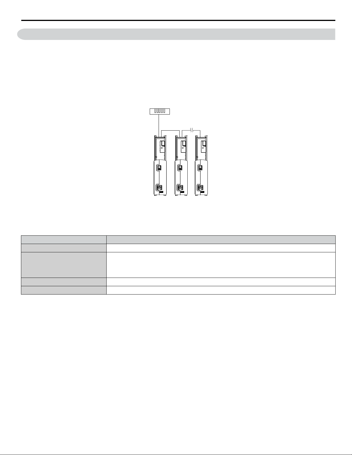
2 N2 Specifications and Configuration
2 N2 Specifications and Configuration
The bypasses can be monitored and controlled by a controller on a Metasys N2 network (N2) using RS-485 technology. The
bypass act as slaves on the N2 network.
Up to 255 bypasses can communicate on a single N2 network. If more bypasses or N2 devices are required, another N2 network
is required.
The N2 node address is configurable by a parameter in the bypass. This defines the physical address of the bypass on the N2
network.
Once the addressing is set, a controller can initiate communication to the bypass. The bypass will perform the specified function
and then send a response back to the controller.
Figure 1 Connecting Multiple Bypasses to a Metasys N2 Network
N2 specifications appear in the following table:
Item Specifications
Interface RS-485
Communication Speed: 9600 bps
Communication Parameters
Protocol Metasys N2
Max Number of Drives 255 per N2 Network Segment
Data Length: 8-bit (fixed)
Parity: None
Stop Bit: 1-bit (fixed)
YASKAWA TOEP YAICOM 12A Z1000 Bypass Network Protocol Metasys® N2 Technical Manual
7
Page 8
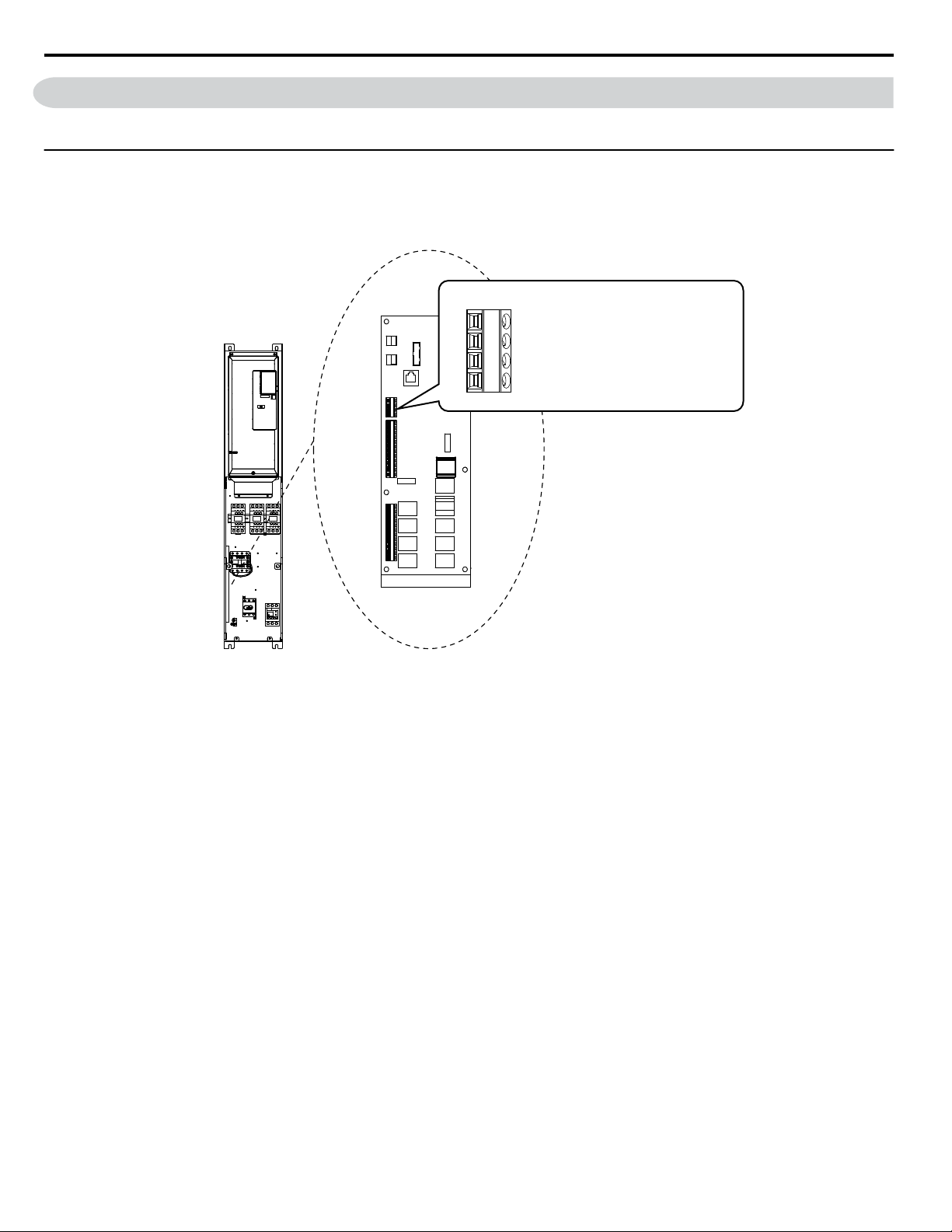
TB3
4
3
2
1
SHLD
TXRX-
TXRX+
IG5
Shield
Transmit/Receive (-)
Transmit/Receive (+)
Isolated Ground Reference
3 Connecting to a Network
3 Connecting to a Network
This section explains how to connect the drive to an N2 network and the network termination required for a connection.
u
Network Cable Connection
Follow the instructions below to connect the bypass to a N2 network.
With the power shut off, connect the communications cable to the bypass controller and the master. Use terminal TB3
1.
for N2.
Figure 2 Serial Communications Cable Connection Terminal (TB3)
Note: Separate the communications cables from the main circuit cables and other wiring and power cables. Use shielded cables for
2.
3.
4.
5.
6.
7.
the communications cables, and properly shielded clamps to prevent problems caused by electrical interference.
Check or set the termination resistor selection at all slaves. Refer to the description in the Network Termination
section for details on the termination resistor.
Switch the power on.
Set the parameters needed for serial communications (Z3-01 through Z3-11) using the digital operator.
Shut the power off and wait until the display on the digital operator goes out completely.
Turn the power back on.
The bypass is now ready to begin communicating with the master.
8
YASKAWA TOEP YAICOM 12A Z1000 Bypass Network Protocol Metasys® N2 Technical Manual
Page 9

u
CONTROLLER
1
2
3
4
+
-
SHLD
Bypass
Bypass
Controller
S1
OFF
TB3
SHLD
TXRX-
TXRX+
IG5
1
2
3
4
Bypass
Bypass
Controller
S1
OFF
TB3
SHLD
TXRX-
TXRX+
IG5
ON
1
2
3
4
Bypass
Bypass
Controller
S1
SHLD
TXRX-
TXRX+
IG5
Wiring Diagram for Multiple Connections
Figure 3 explains the wiring diagrams for multiple connections using N2 communication.
RS-485 Interface
n
3 Connecting to a Network
Figure 3 RS-485 Interface
Note: Turn on DIP switch S1 on the bypass that is located at the end of the network. If S1 is missing, then an external 120 ohm resistor must be
placed across terminals TXRX+ and TXRX-. All other slave devices must have this DIP switch set to the OFF position (or if S1 is missing,
no external resistor must be used).
u
Network Termination
The two ends of the network line must be terminated with a 120 ohm resistor between the TXRX+ and TXRX- signals. The
Z1000 Bypass has a built in termination resistor that can be enabled or disabled using DIP switch S1. If a bypass is located at
the end of a network line, enable the termination resistor by setting DIP switch S1 to the ON position. Disable the termination
resistor on all slaves that are not located at the network line end.
Note: Some bypass controllers do not have DIP switch S1. in such cases an external 120 ohm resistor must be placed across the
TXRX+ and TXRX- signals if the bypass controller is at the end of a network line.
YASKAWA TOEP YAICOM 12A Z1000 Bypass Network Protocol Metasys® N2 Technical Manual
9
Page 10

4 N2 Setup Parameters
4 N2 Setup Parameters
u
N2 Serial Communication
This section describes parameters necessary to set up N2 communications.
Z3-01: Serial Communications Protocol Select
n
Selects the communications protocol.
No. Name Setting Range Default
Z3-01 Serial Communications Protocol Selection 0 to 3 0
Setting 0: MEMOBUS/Modbus
Setting 1: N2
Setting 2: P1
Setting 3: BACnet
Z3-02: Serial Communications Node Address Select
n
Sets the drive slave address used for communications.
Note: Cycle the power after changing this parameter to enable the new setting.
No. Name Setting Range Default
Z3-02 Serial Communications Node Address Select 0 to FFH 1FH
Each slave drive must be assigned a unique slave address for serial communications to work. Slave addresses do not need to
be assigned in sequential order, but no two drives may share the same address.
Z3-03: Serial Communications Baud Rate Select
n
Sets the communication speed.
Note: 1. Cycle the power after changing this parameter to enable the new setting.
No. Name Setting Range Default
Z3-03 Serial Communications Baud Rate Select 0 to 8 3
Z3-03 Communication Speed Z30 Z3–03 Communication Speed
0 1200 bps 4 19200 bps
1 2400 bps 5 38400 bps
2 4800 bps 6 57600 bps
3 9600 bps 7 76800 bps
– – 8 115200 bps
Z3-04: Serial Communications Parity Select
n
Sets the parity used for communications.
Note: Cycle the power after changing this parameter to enable the new setting.
No. Name Setting Range Default
Z3-04 Serial Communications Parity Select 0 to 2 0
Setting 0: No parity
Setting 1: Even parity
Setting 2: Odd parity
Z3-05: Serial Communications Fault Select
n
Selects the action to take when a serial communications fault is selected. If communications is lost for more than the time
programmed in Z3-06, then a communication fault is detected.
Note: Cycle the power after changing this parameter to enable the new setting.
10
YASKAWA TOEP YAICOM 12A Z1000 Bypass Network Protocol Metasys® N2 Technical Manual
Page 11

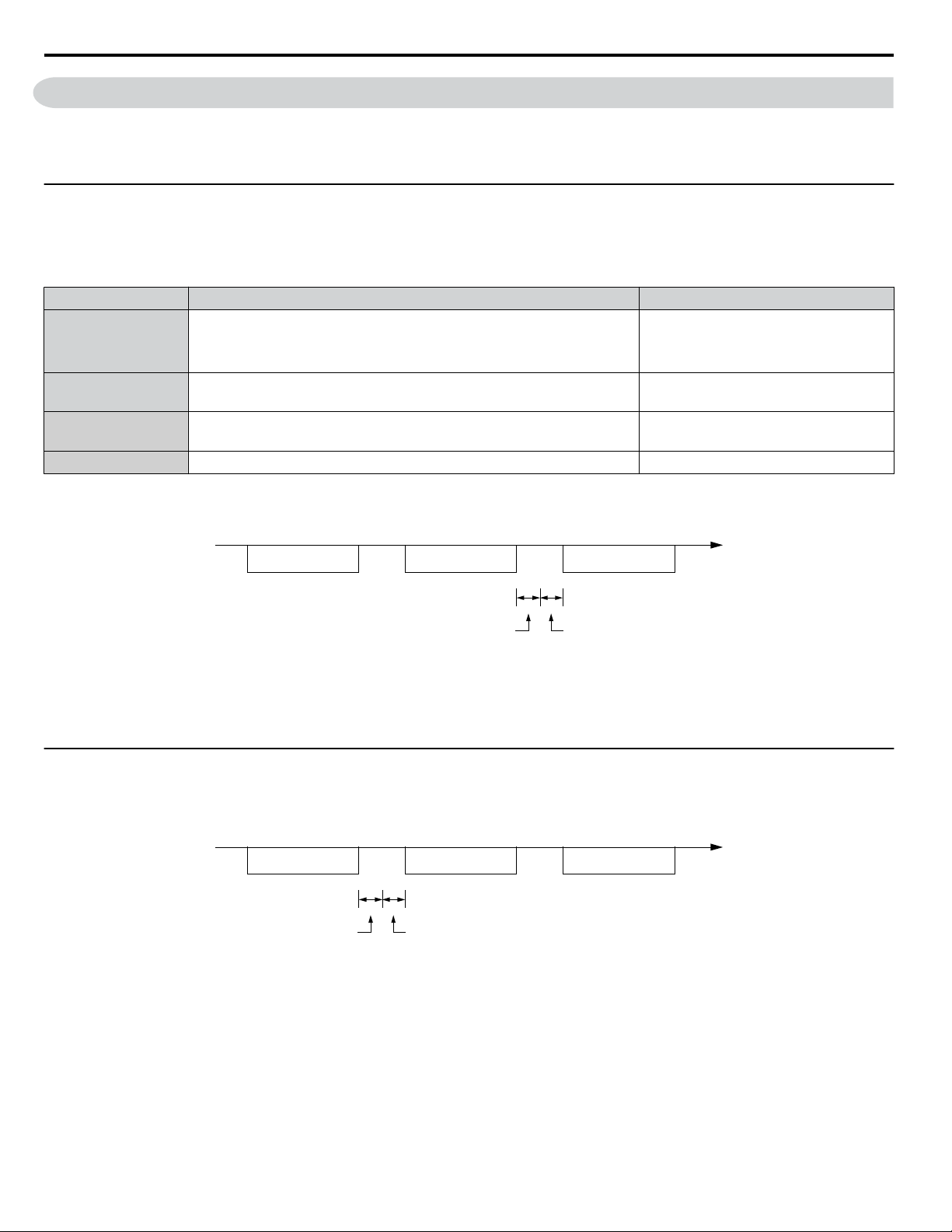
Command message Response message Command message
Controller→Bypass →Bypass
→
Time
24-bit length
Z3-07 setting
Bypass Controller
Controller
4 N2 Setup Parameters
No. Name Setting Range Default
Z3–05 Serial Communications Fault Select 0 to 4 1
Setting 0: Ignore
Setting 1: Alarm
Setting 2: Fault with EF0.
Fault FB14 will display in the operator and an EF0 fault will be sent to the drive.
Setting 3: Fault with EF0 and Open Bypass Contactor K3.
Fault FB14 will display in the operator, an EF0 fault will be sent to the drive, and bypass contactor K3 will be opened.
Setting 4: Alarm and run at preset speed set in Z3-10.
Alarm AL14 will display in the operator.
Z3-06: Serial Communications Fault Time Select
n
Sets the time allowed to elapse since receiving serial communications before triggering a communications fault. A value of
0.0 means to never time out.
No. Name Setting Range Default
Z3-06 Serial Communications Fault Detection Time 0.0 to 99.9 s 2.0 s
Z3-07: Serial Communications Receive to Transmit Wait Time
n
Sets the time to delay a serial communications response to a serial communications command.
No. Name Setting Range Default
Z3-07 Serial Communications Receive to Transmit Wait Time 0 to 99 ms 5 ms
Figure 4 Serial Communications Receive to Transmit Wait Time Setting
Z3-10: Cable Loss Pre-set Speed
n
When a serial communicaions fault is detected and Z3-05=4, the value here will become the frequency reference.
No. Name Setting Range Default
Z3-10 Cable Loss Pre-set Speed 0.0 to 60.0 Hz 0.0 Hz
Z3-11: Serial Communication Fault Detection Selection
n
Enables or disables the serial communications fault detection.
No. Name Setting Range Default
Z3-11 Serial Communication Fault Detection Selection 0 or 1 1
Setting 0: Disabled
No communication error detection. Ignore setting in Z3-05.
Setting 1: Enabled
If the bypass does not receive data from the master for longer than the time set to Z3-06, then a FB14 Serial Communicaions
fault will be triggered and the bypass will operate as determined by parameter Z3-05.
YASKAWA TOEP YAICOM 12A Z1000 Bypass Network Protocol Metasys® N2 Technical Manual
11
Page 12

5 Bypass Operations by N2
5 Bypass Operations by N2
The drive operations that can be performed by N2 communication depend on drive parameter settings. This section explains
the functions that can be used and related parameter settings.
u
Observing the Bypass Operation
A controller can perform the following actions with N2 communications at any time regardless of parameter settings (except
for Z3-oo parameters):
• Observe drive status and drive control terminal status from a controller
• Read and write parameters
• Set and reset faults
• Set multi-function inputs.
Note:
u
Controlling the Bypass
Select an external reference and adjust the parameters in Table 1 accordingly to start and stop the drive or set the frequency
reference using N2 communications.
Input settings from the input terminals So and from N2 communications are both linked by a logical OR operation.
Table 1 Setting Parameters for Bypass Control from N2
Reference Source Parameter Name Required Setting
External Reference 1
Z1-07 Frequency Reference Select 2
Z1-08 Run Command Select 2
Refer to the Z1000 Bypass Technical Manual for details on external reference parameter selections.
Z1000 Bypass Functions
n
Each of the following functions must be enabled during start-up:
Start and Stop the Bypass
Set the Run Forward Command (BO 1) to run the in the forward direction. Set the Run Reverse Command (BO 2) to run the
in the reverse direction. Run/Stop Monitor (BI 1) shows the current run status. Forward/Reverse Monitor (BI 2) shows the
current direction.
NOTICE: Damage to Equipment. Improper motor direction may damage HVAC equipment if parameter b1-04, Reverse Enable, is set to 0
(Enable).
Lock the Z1000 Bypass Panel
This function is not supported in the Z1000 Bypass.
Digital Inputs
Multi-Function Input S3 (BO 5) through Multi-Function Input S7 (BO 9) are physical digital inputs on the bypass. They can
be set either by external devices, such as limit or pressure switches, or by the network. Their function depends on how the
bypass has been programmed. Refer to the Z1000 Bypass Technical Manual section on Multi-Function Inputs (Z2-03 through
Z2-07) for detailed information on the use and programming of the multi-function inputs. The multi-function input status can
be monitored through Multi-Function Input 3 Monitor (BI 15) through Multi-Function Input 7 Monitor (BI 19). The MultiFunction Input # Monitor state is the logical OR of the serial command value (BO 5 through BO 9) and the state of the external
connection.
Note: The multi-function inputs can be set by both external devices or over the network. Use caution when connecting the multi-function inputs
Digital Outputs
to external devices to ensure correct system operation.
Multi-Function Output 7 (BI 10) through Multi-Function Output 9 (BI 12) are physical digital outputs on the bypass. Their
function depends on how the bypass is programmed. Refer to the Z1000 Bypass Technical Manual section on Multi-Function
Outputs (Z2-23 through Z2-25) for detailed information on the use and programming of the multi-function outputs.
Loop Gain
PI Proportional Gain (AO 4) and PI Integral Time (AO 5) are the gain and integral time parameters used by the Z1000. The
Z1000 PI loop is structured differently than the Metasys loop. Refer to the Z1000 Bypass Technical Manual section on PI for
information on Z1000 PI loop functions.
12
YASKAWA TOEP YAICOM 12A Z1000 Bypass Network Protocol Metasys® N2 Technical Manual
Page 13

5 Bypass Operations by N2
Reading and Resetting Faults
The Fault Monitor (BI 4) and Drive Ready Monitor (BI 3) show the current status of the bypass. The Fault Code (AI 10)
contains the code for the most current fault. The LST Fault Code (AI 19) contains the code for the previous drive fault. Refer
to Fault Trace / History Register Contents on page 14 for descriptions of the fault codes. The drive faults can be reset
through the Fault Reset Command (BO 4). The Fault Reset Command is only available when the Run Forward Command and
the Run Reverse Command are both OFF.
Cable Loss Configuration and Behavior
n
This section describes the configurable cable loss feature of the drive. This feature offers a user maximum flexibility in
determining drive response to a loss of communication.
Drive Behavior at Loss of Communication
The drive can be configured to respond to an interval without receipt of a message in one of the following methods:
• Continue at last speed
• Continue at last speed with alarm
• Continue at preset speed
• Ramp to Stop with FB14 fault
• Coast to Stop with FB14 fault
• Emergency Stop with FB14 fault
Metasys N2 I/O
Three Metasys N2 outputs are used to select the desired behavior:
• AO 21 – Cable Loss Timeout
• AO 22 – Cable Loss Speed
• BO 11 – Communication Fault Enable
Table 2 Cable Loss Behavior Summary
Behavior F6-03 Z3-05
Decelerate to stop (stop time in C1-02) FB14
Fault.
Note: In Bypass mode, bypass
contactor will open and motor
will coast to stop.
Coast to stop FB14 fault.
Note: In Bypass mode, bypass
contactor will open and motor
will coast to stop.
Fast stop (stop time in C1-09) FB14 fault.
Note: In Bypass mode, bypass
contactor will open and motor
will coast to stop.
Continue at last speed 3 0 0 X X
Continue at last speed with alarm 3 1 Timeout Interval X On
Continue at preset speed with alarm 3 4 Timeout Interval Preset speed On
Note: 1. Communication must first be established and then lost for these features to function as described. If a bypass is powered-up without a
cable connected or with the master controller offline, a communications timeout does not occur.
2. For modes that describe the bypass running after a communications timeout, a run command must have been issued (BO 1 = ‘On’ or
BO 2 = ‘On’) prior to loss of communications. For safety purposes, the drive will not automatically restart from a stopped condition. If
a user requires the drive to restart automatically, additional external wiring is required to accomplish this (consult factory).
3. Upon expiration of the communications timeout interval, the FAULT LED lights and remains lit until communication is restored.
0 3 Timeout Interval X On
1 3 Timeout Interval X On
2 3 Timeout Interval X On
Cable Loss Timeout
(AO 21)
Cable Loss Speed
(AO 22)
Communication Fault
Enable
(BO 11)
Continue at Last Speed
In this mode, Cable Loss Timeout (AO 21) is set to 0, disabling the cable loss feature. The other two settings Cable Loss Speed
(AO 22) and Communication Fault Enable (BO 11) are ignored. If communication is lost, the drive simply maintains its last
commanded state. The drive will not display an alarm or fault to indicate it has lost communication. This behavior can also
be achieved by setting parameter Z3–05 to “0”.
Continue at Last Speed with Alarm
YASKAWA TOEP YAICOM 12A Z1000 Bypass Network Protocol Metasys® N2 Technical Manual
13
Page 14

5 Bypass Operations by N2
For this condition, Communication Fault Enable (BO 11) must be enabled and Cable Loss Speed (AO 22) should be set to a
value other than 0. An AL14 Serial Communications Alarm is shown.
Continue at Preset Speed with Alarm
In this mode, Cable Loss Timeout (AO 21) is set to the desired interval, Cable Loss Speed (AO 22) is set to the desired preset
speed and Z3–05 is set to “4”. If the time between messages exceeds the timeout interval, the drive speed command (AO 1)
is set to the Cable Loss Speed (AO 22) and the drive continues running at this new speed. Communication Fault Enable (BO
11) must be set to ‘On’.
Stop with Fault (FB14)
Communication Fault Enable (BO 11) must be set to ‘On’. In this mode, Cable Loss Timeout (AO 21) is set to the desired
interval and parameter F6-03 is set to a value of 0,1 or 2. If the time between messages exceeds the timeout interval, the drive
will declare an EF0 fault and the drive speed command (AO 1) will be set to 0. The stopping method is determined by the
setting of F6-03.
• F6–03 = 0 selects Ramp to Stop. The deceleration time or the slope of the ramp is determined by the setting of drive parameter
C1-02
• F6–03 = 1 selects Coast to Stop. The drive does not attempt to control the rate of deceleration.
• F6–03 = 2 selects Emergency or Fast Stop. The deceleration time is determined by the setting of drive parameter C1-09.
Z1000 Bypass Fault Numbers
n
Table 3 Fault Trace / History Register Contents
Fault Code Fault Name
0002H Undervoltage (Uv1)
0003H Control Power Supply Undervoltage (Uv2)
0004H Soft Charge Circuit Fault (Uv3)
0006H Ground Fault (GF)
0007H Overcurrent (oC)
0008H Overvoltage (ov)
0009H Heatsink Overheat (oH)
000AH Heatsink Overheat (oH1)
000BH Motor Overload (oL1)
000CH Drive Overload (oL2)
000DH Overtorque Detection 1 (oL3)
0010H Braking Resistor Overheat (rH)
0011H External Fault at Input Terminal S3 (EF3)
0012H External Fault at Input Terminal S4 (EF4)
0013H External Fault at Input Terminal S5 (EF5)
0014H External Fault at Input Terminal S6 (EF6)
0015H External Fault at Input Terminal S7 (EF7)
001BH Input Phase Loss (PF)
001CH Output Phase Loss (LF)
001DH Motor Overheat (PTC input) (oH3)
001EH Digital Operator Connection (oPr)
001FH EEPROM Write Error (Err)
0020H Motor Overheat (PTC input) (oH4)
0021H MEMOBUS/Modbus Communication Error (CE)
0022H Option Communication Error (bUS)
0027H Option External Fault (EF0)
0028H PI Feedback Loss (FbL)
0029H Undertorque Detection 1 (UL3)
002BH High Slip Braking Overload (oL7)
0030H Hardware Fault (including oFx)
0036H Output Current Imbalance (LF2)
0037H Pullout Detection (Sto)
Fault Code Fault Name
003BH Too Many Speed Search Restarts (SEr)
0041H PI Feedback Loss (FbH)
0042H External Fault 1, Input Terminal S1 (EF1)
0043H External Fault 2, Input Terminal S2 (EF2)
0046H Current Offset Fault (CoF)
0047H PLC Detection Error 1 (PE1)
0048H PLC Detection Error 2 (PE2)
004DH Output Voltage Detection Fault (voF)
0052H Node Setup Fault (nSE)
005AH Motor Underload Protection (UL6)
0083H A/D Conversion Error (CPF02)
0084H PWM Data Fault (CPF03)
0087H EEPROM Memory Data Error (CPF06)
0088H Terminal Board Connection Error (CPF07)
0089H EEPROM Serial Communication Fault (CPF08)
008CH RAM Fault (CPF11)
008DH Flash Memory Circuit Exception (CPF12)
008EH Watchdog Circuit Exception (CPF13)
008FH Control Circuit Fault (CPF14)
0091H Clock Fault (CPF16)
0092H Timing Fault (CPF17)
0093H Control Circuit Fault (CPF18)
0094H Control Circuit Fault (CPF19)
0095H Hardware Fault at Power Up (CPF20)
0096H Hardware Fault at Communication Start Up (CPF21)
0097H A/D Conversion Fault (CPF22)
0098H PWM Feedback Fault (CPF23)
0099H Drive Unit Signal Fault (CPF24)
009AH Terminal Board is Not Properly Connected. (CPF25)
009BH ASIC BB Circuit Error (CPF26)
009CH ASIC PWM Setting Register Error (CPF27)
009DH ASIC PWM Pattern Error (CPF28)
14
YASKAWA TOEP YAICOM 12A Z1000 Bypass Network Protocol Metasys® N2 Technical Manual
Page 15

5 Bypass Operations by N2
Fault Code Fault Name
009EH ASIC On-delay Error (CPF29)
009FH ASIC BBON Error (CPF30)
00A0H ASIC Code Error (CPF31)
00A1H ASIC Start-up Error (CPF32)
00A2H Watch-dog Error (CPF33)
00A3H ASIC Power/Clock Error (CPF34)
00A4H External A/D Converter Error (CPF35)
00A9H Control Circuit Error (CPF40)
00AAH Control Circuit Error (CPF41)
00ABH Control Circuit Error (CPF42)
00ACH Control Circuit Error (CPF43)
00ADH Control Circuit Error (CPF44)
00AEH Control Circuit Error (CPF45)
0101H Option Compatibility Error (oFA00)
0102H Option Not Properly Connected (oFA01)
0106H A/D Conversion Error (oFA05)
0107H Option Response Error (oFA06)
0111H Option RAM Fault (oFA10)
0112H Option Operation Mode Fault (SLMOD) (oFA11)
0113H Drive Receive CRC Error (oFA12)
0114H Drive Receive Frame Error (oFA13)
0115H Drive Receive Abort Error (oFA14)
0116H Option Receive CRC Error (oFA15)
0117H Option Receive Frame Error (oFA16)
0118H Option Receive Abort Error (oFA17)
0131H Comm. ID Error (oFA30)
0132H Model Code Error (oFA31)
0133H Sumcheck Error (oFA32)
0134H
0135H MEMOBUS Timeout (oFA34)
Comm. Option Timeout Waiting for Response
(oFA33)
Fault Code Fault Name
0136H Drive Timeout Waiting for Response (oFA35)
0137H CI Check Error (oFA36)
0138H Drive Timeout Waiting for Response (oFA37)
0139H Control Command Selection Error (oFA38)
013AH Drive Timeout Waiting for Response (oFA39)
013BH Control Response Selection 1 Error (oFA40)
013CH Drive Timeout Waiting for Response (oFA41)
013DH Control Response Selection 2 Error (oFA42)
013EH Control Response Selection Error (oFA43)
0401H Time Not Set (TIM)
0402H Operator Battery Low (bAT)
0403H Time Data Error (TdE)
0404H Time Interval Error (TiE)
0405H Overvoltage 2 (ov2)
0407H External Fan Fault (Fn1)
1389H Safety Open
138AH BAS InterLock Open
138BH External Fault (EFB)
138CH Not Used
138DH Motor Overload
138EH Ext Motor1 Overload
138FH Ext Motor2 Overload
1390H PL Brownout
1391H PL Blackout
1392H No Bypass to Drive Communications
1393H Bypass Board Hardware Error
1394H Option Board Communication Fault
1395H Loss of Load
1396H Serial Communications Timeout
YASKAWA TOEP YAICOM 12A Z1000 Bypass Network Protocol Metasys® N2 Technical Manual
15
Page 16
Command message Response message Command message
Controller→Bypass Controller→BypassBypass →Controller
24 bit length
Master Send
Wait Time
Time
Time
Command message Response message Command message
→ →→
24 bit length
Z3-07 setting
Controller Bypass
Bypass Controller
Controller Bypass
6 Communications Timing
6 Communications Timing
To prevent a communications overrun in the slave drive, the master should wait a certain time between sending messages to
the same drive. In the same way, the slave drive must wait before sending response messages to prevent an overrun in the
master. This section explains the message timing.
u
Command Messages from Master to Bypass
The master must wait for a specified time between receiving a response and resending the same type of command to the same
slave bypass to prevent overrun and data loss. The minimum wait time depends on the command as shown in Table 4.
Table 4 Minimum Wait Time for Sending Messages
Command Type Example Minimum Wait Time
• Control command (Run, Stop)
1
• Set inputs/outputs
• Read monitors and parameter values
2 Write parameters
3 Save changes using an Enter command
H5-11 = 0: 50 ms
H5-11 = 1: 200 ms
200 ms to 2 s, depending on the number
of parameters that were changed
4 Enter with storage to drive EEPROM after initialization 5 s
<1> If the bypass receives command type 1 data during the minimum wait time, it will perform the command and then respond. However, if it receives
a command type 2 or 3 during that time, either a communication error will result or the command will be ignored.
5 ms
<1>
<1>
<1>
Figure 5 Minimum Wait Time for Sending Messages
Set a timer in the master to check how long it takes for the slave bypass units to respond to the master. If no response is received
within a certain amount of time, the master should try resending the message.
u
Response Messages from Bypass to Master
If the bypass receives a command from the master, it will process the data received and wait for the time set in Z3-07 until it
responds. Increase Z3-07 if the drive response causes overrun in the master.
Figure 6 Minimum Response Wait Time
16
YASKAWA TOEP YAICOM 12A Z1000 Bypass Network Protocol Metasys® N2 Technical Manual
Page 17

7 Metasys N2 Point Database
7 Metasys N2 Point Database
This section describes the Metasys N2 point database. This database features 100 logical points: 38 Analog Inputs (AI), 32
Analog Outputs (AO), 19 Binary Inputs (BI) and 11 Binary Outputs (BO). These points configure, control, and monitor the
operation of the drive.
u
Metasys N2 Analog Input (AI) Summary
Table 5 Metasys N2 Analog Input Summary (Bypass to Metasys N2)
Object ID Object Name Units Bypass Parameter
AI 1 Speed Reference 0.01 Hz U1-01
AI 2 Output Speed 0.01 Hz U1-02
AI 3 Output Current 0.1 A U1-03/UB-01 in Drive/Bypass Mode
AI 4 kWatt Hour Meter kWh U4-10
AI 5 Output Power 0.1 kWh U1-08
AI 6 Drive Temperature
AI 7 PI Feedback 0.01% U5-01
AI 8 AC Output Voltage 0.1 Vac U1-06
AI 9 DC Bus Voltage 1 Vdc U1-07
AI 10 Fault Code – U2-01/UB-09. Reads UB-09 first and if 0 returns U2-01
AI 11 Elapsed Time - Hours 1 hour U4-01
AI 12 Elapsed Time - 10K Hours 10K hours U4-01
AI 13 MWatt Hour meter MWh U4-11
AI 14 Drive Rated Current A n9-01
AI 15 Communication Error Code – Not supported. Always returns 0
1 °C
U4-08
AI 16 PI Deviation 0.01% U5-02
AI 17 PI Output Capacity 0.01% U5-03
AI 18 PI Reference 0.01% U5-04
AI 19 Last Fault Code – U2-02
AI 20 Freq Ref @ Fault 0.01 Hz U2-03
AI 21 Output Freq @ Fault 0.01 Hz U2-04
AI 22 Output Current @ Fault 0.1 A U2-05
AI 23 Out Volt Ref @ Fault 0.1 Vac U2-07
AI 24 DC Bus Volts @ Fault 1 Vdc U2-08
AI 25 Output Power @ Fault 0.1 kW U2-09
AI 26 Input Term Status @ Fault – U2-11
AI 27 Output Term Status @ Fault – U2-12
AI 28 Operation Status @ Fault – U2-13
AI 29 Elapsed Operation Time @ Fault 1 hour U2-14
AI 30 Most Recent Fault – U3-01
AI 31 2nd Most Recent Fault – U3-02
AI 32 3rd Most Recent Fault – U3-03
AI 33 4th Most Recent Fault – U3-04
AI 34 Elapsed Time @ Current Fault 1 hour U3-11
AI 35 Elapsed Time @ 2nd Fault 1 hour U3-12
AI 36 Elapsed Time @ 3rd Fault 1 hour U3-13
AI 37 Elapsed Time @ 4th Fault 1 hour U3-14
AI 38 Read Parameter Data – –
YASKAWA TOEP YAICOM 12A Z1000 Bypass Network Protocol Metasys® N2 Technical Manual
17
Page 18

7 Metasys N2 Point Database
u
Metasys N2 Analog Output (AO) Summary
Table 6 Metasys N2 Analog Output Summary (Bypass to Metasys N2)
Object ID Object Name Units Default Value Bypass Parameter
AO 1 Speed Command 0.01 Hz – –
AO 2 Acceleration Time seconds 30.0 C1-01
AO 3 Deceleration Time seconds 30.0 C1-02
AO 4 PI Proportional Gain – 2.00 b5-02
AO 5 PI Integral Time seconds 5.0 b5-03
AO 6 Stall Prevention Level – Run % 120 L3-06
AO 7 Stall Prevention Level – Accel % 120 L3-02
AO 8 Frequency Reference Selection – 0 Z1-07
AO 9 Run Command Selection – 1 Z1-08
AO 10 PI Mode Select – 0 b5-01
AO 11 Frequency Command Upper Limit % of Max 100.0 d2-01
AO 12 Frequency Command Lower Limit % of Max 0.0 d2-02
AO 13 Motor Rated Current A Motor model dependent E2-01
AO 14 Jump Frequency 1 0.1 Hz 0.0 d3-01
AO 15 Jump Frequency 2 0.1 Hz 0.0 d3-02
AO 16 Jump Frequency 3 0.1 Hz 0.0 d3-03
AO 17 Jump Frequency Bandwidth 0.1 Hz 1.0 d3-04
AO 18 Number of Auto Restarts – 0 L5-01
AO 19 Operator Display Mode – 0 o1-03
AO 20 Power Loss Ride-Thru seconds Drive model dependent L2-02
AO 21 Cable Loss Timeout seconds 2.0 Z3-06
AO 22 Cable Loss Speed 0.01 Hz 0.00 Z3-10
AO 23 PI Integral Limit 0.1% 100.0 b5-04
AO 24 PI Upper Limit Value 0.1 100.0 b5-06
AO 25 PI Offset Adjustment 0.1 0.0 b5-07
AO 26 PI Primary Delay Time 0.01 0.00 b5-08
AO 27
AO 28
AO 29
AO 30 Read Parameter Number – – –
AO 31 Write Parameter Number – – –
AO 32 Write Parameter Data – – –
PI Feedback Reference Missing
Detection Select
PI Feedback Reference Missing
Detection Level
PI Feedback Reference Missing
Detection Time
1 0 b5-12
1% 0 b5-13
0.1 s 1.0 b5-14
u
Metasys N2 Binary Input (BI) Summary
Table 7 Metasys N2 Binary Input Summary (Bypass to Metasys N2)
Object ID Object Name Default Off (0) State On (1) State
BI 1 Run/Stop Monitor 0 Stopped Running
BI 2 Forward/Reverse Monitor 0 Forward Reverse
BI 3 Drive Ready Monitor 0 Not Ready Ready
BI 4 Fault Monitor 0 Not Faulted Faulted
BI 5 Zero Speed 0 Not Zero Speed Zero Speed
BI 6 Speed Agree 0 Not Speed Agree Speed Agree
BI 7 Minor Fault 0 No Minor Fault Minor Fault
BI 8 Major Fault 0 No Major Fault Major Fault
BI 9 Drive Communication Error Monitor 0 No Error Error
18
YASKAWA TOEP YAICOM 12A Z1000 Bypass Network Protocol Metasys® N2 Technical Manual
Page 19

7 Metasys N2 Point Database
Object ID Object Name Default Off (0) State On (1) State
BI 10 Multi-Function Output 7 (Z2-23) 0 Off On
BI 11 Multi-Function Output 8 (Z2-24) 0 Off On
BI 12 Multi-Function Output 9 (Z2-25) 0 Off On
BI 13 Safety Interlock Monitor 0 Safety Clear Safety Set
BI 14 HAND/AUTO Reference Monitor 0 AUTO or OFF HAND
BI 15 Multi-Function Input 3 Monitor 0 Off On
BI 16 Multi-Function Input 4 Monitor 0 Off On
BI 17 Multi-Function Input 5 Monitor 0 Off On
BI 18 Multi-Function Input 6 Monitor 0 Off On
BI 19 Multi-Function Input 7 Monitor 0 Off On
u
Metasys N2 Binary Output (BO) Summary
Table 8 Metasys N2 Binary Output Summary (Bypass to Metasys N2)
Object ID Object Name Default Off (0) State On (1) State
BO 1 Run Forward Command 0 Stop Forward
BO 2 Run Reverse Command 0 Stop Reverse
BO 3 External Fault (EFB) Command 0 No Fault Fault (EFB)
BO 4 Fault Reset Command 0 No Reset Reset
BO 5 Multi-Function Input 3 (Z2-03) 0 Off On
BO 6 Multi-Function Input 4 (Z2-04) 0 Off On
BO 7 Multi-Function Input 5 (Z2-05) 0 Off On
BO 8 Multi-Function Input 6 (Z2-06) 0 Off On
BO 9 Multi-Function Input 7 (Z2-07) 0 Off On
BO10
BO 11 Communication Fault Enable 0 FB14 Not Activated if Cable Loss Occurs FB14 Activated if Cable Loss Occurs
Panel Lock
Note: Not supported
0 – –
YASKAWA TOEP YAICOM 12A Z1000 Bypass Network Protocol Metasys® N2 Technical Manual
19
Page 20

8 Mailbox Function
8 Mailbox Function
u
Reading Drive Parameters
Two points are defined for reading drive parameters:
• AO 30 – Specifies the parameter to be read from the bypass.
• AI 38 – Reports the value of the parameter specified in AO 30.
When this point is read, it retrieves data from the parameter and sends it to the controller
Example: Writing a value of 387 (183 hex) to AO 30 specifies drive parameter b1-04. Reading AI 38 returns the current setting
of parameter b1-04 to the controller.
u
Writing Drive Parameters
Two points are defined for writing to drive parameters:
• AO 31 – Specifies the parameter to be written to
• AO 32 – Entry location of the value to be written to the parameter specified in AO 31. When this point is written to, it will
write the value to the drive. An ENTER or ACCEPT command does not need to be sent for the data to be taken by the drive.
The behavior of the write is the same as with the digital operator. If the drive is running, there are a limited number of drive
parameters that can be written to.
Example: Writing a value of 387 (183 hex) to AO 31 specifies drive parameter b1-04. Writing a value of 1 to AO 32 sets b1-04
to 1 and disables the drive for reverse run.
20
YASKAWA TOEP YAICOM 12A Z1000 Bypass Network Protocol Metasys® N2 Technical Manual
Page 21

9 Revision History
The revision dates and the numbers of the revised manuals appear on the bottom of the back cover.
9 Revision History
Date of Publication
September 2012 - - First Edition.
Revision
Number
Section Revised Content
YASKAWA TOEP YAICOM 12A Z1000 Bypass Network Protocol Metasys® N2 Technical Manual
21
Page 22

9 Revision History
This Page Intentionally Blank
22
YASKAWA TOEP YAICOM 12A Z1000 Bypass Network Protocol Metasys® N2 Technical Manual
Page 23

Page 24

Yaskawa AC Drive - Z1000 Bypass Network Protocol
Metasys N2
Technical Manual
YASKAWA AMERICA, INC.
2121 Norman Drive South, Waukegan, IL 60085, U.S.A.
Phone: (800) YASKAWA (927-5292) or 1-847-887-7000 Fax: 1-847-887-7310
http://www.yaskawa.com
DRIVE CENTER (INVERTER PLANT)
2-13-1, Nishimiyaichi, Yukuhashi, Fukuoka, 824-8511, Japan
Phone: 81-930-25-3844 Fax: 81-930-25-4369
http://www.yaskawa.co.jp
YASKAWA ELECTRIC CORPORATION
New Pier Takeshiba South Tower, 1-16-1, Kaigan, Minatoku, Tokyo, 105-6891, Japan
Phone: 81-3-5402-4502 Fax: 81-3-5402-4580
http://www.yaskawa.co.jp
YASKAWA ELÉTRICO DO BRASIL LTDA.
®
Avenda Fagundes Filho, 620 Bairro Saude, São Paulo, SP04304-000, Brasil
Phone: 55-11-3585-1100
http://www.yaskawa.com.br
YASKAWA EUROPE GmbH
Hauptstrasse 185, 65760 Eschborn, Germany
Phone: 49-6196-569-300 Fax: 49-6196-569-398
http://www.yaskawa.eu.com
YASKAWA ELECTRIC UK LTD.
1 Hunt Hill Orchardton Woods, Cumbernauld, G68 9LF, United Kingdom
Phone: 44-1236-735000
http://www.yaskawa.co.uk
YASKAWA ELECTRIC KOREA CORPORATION
7F, Doore Bldg. 24, Yeoido-dong, Yeoungdungpo-gu, Seoul, 150-877, Korea
Phone: 82-2-784-7844
http://www.yaskawa.co.kr
YASKAWA ELECTRIC (SINGAPORE) PTE. LTD.
151 Lorong Chuan, #04-01, New Tech Park, 556741, Singapore
Phone: 65-6282-3003
http://www.yaskawa.com.sg
YASKAWA ELECTRIC (SHANGHAI) CO., LTD.
No. 18 Xizang Zhong Road, 17F, Harbour Ring Plaza, Shanghai, 200001, China
Phone: 86-21-5385-2200
http://www.yaskawa.com.cn
YASKAWA ELECTRIC (SHANGHAI) CO., LTD. BEIJING OFFICE
Room 1011, Tower W3 Oriental Plaza, No. 1 East Chang An Ave.,
Dong Cheng District, Beijing, 100738, China
Phone: 86-10-8518-4086
YASKAWA ELECTRIC TAIWAN CORPORATION
9F, 16, Nanking E. Rd., Sec. 3, Taipei, 104, Taiwan
Phone: 886-2-2502-5003
Fax: 55-11-5581-8795
Fax: 44-1236-458182
Fax: 82-2-784-8495
Fax: 65-6289-3003
Fax: 86-21-5385-3299
Fax: 86-10-8518-4082
Fax: 886-2-2505-1280
YASKAWA AMERICA, INC.
In the event that the end user of this product is to be the military and said product is to be employed in any weapons systems or the manufacture
thereof, the export will fall under the relevant regulations as stipulated in the Foreign Exchange and Foreign Trade Regulation s. Therefore, be sure
to follow all procedures and submit all relevant documentation according to any and all rules, regulations and laws that may apply.
Specifications are subject to change without notice for ongoing product modifications and improvements.
© 2012 YASKAWA AMERICA, INC. All rights reserved.
MANUAL NO. TOEP YAICOM 12A
Published in U.S.A. September 2012 12-9
 Loading...