


 Loading...
Command Link Plus
Multifunction
Color Gauge
OWNER’S MANUAL
U.S.A.Edition
 Read this manual carefully before using the Command Link Plus Multifunction Color Gauge.
LIT-18626-09-13 6Y9-2819U-E0
Read this manual carefully before using the Command Link Plus Multifunction Color Gauge. Keep this manual onboard in a waterproof bag when boating. This manual should stay with the Command Link Plus Multifunction Color Gauge if it is sold.
Important manual information
To the owner
Thank you for selecting the Command Link Plus Multifunction Color Gauge (hereinafter called the Multi-Display). This Owner's Manual contains information needed for proper operation. A thorough understanding of these simple instructions will help you obtain maximum enjoyment from your new Yamaha. If you have any question about the operation of the MultiDisplay, please consult a Yamaha dealer.
In this Owner's Manual particularly important information is distinguished in the following ways.
This is the safety alert symbol. It is used to alert you to potential personal injury hazards. Obey all safety messages that follow this symbol to avoid possible injury or death.
 WARNING
A WARNING indicates a hazardous situation which, if not avoided, could result in death or serious injury.
NOTICE
A NOTICE indicates special precautions that must be taken to avoid damage to the outboard motor or other property.
TIP:
A TIP provides key information to make procedures easier or clearer.
Information about the owner's manual
Yamaha continually seeks advancements in product design and quality. Therefore, while this manual contains the most current product information available at the time of printing, there may be minor discrepancies between your machine and this manual.
Command Link Plus Multifunction Color Gauge
OWNER'S MANUAL
©2010 by Yamaha Motor Corporation, U.S.A. 2nd Edition, March 2010
All rights reserved.
Any reprinting or unauthorized use without the written permission of Yamaha Motor Corporation, U.S.A. is expressly prohibited.
Printed in Japan
P/N LIT-18626-09-13
Safety information
Safety information
The Multi-Display will notify the operator when engine abnormalities occur by displaying a pop-up window and alert icons. A pop-up window will also be displayed when specific alert conditions occur.
When events requiring multiple pop-up windows occur, the pop-up window with the highest priority is displayed first. Press the “SET” button to display pop-up windows in order of priority.
There are 3 types of pop-up windows, “Alert Notifications,” “Maintenance Notifications,” and “Other Notifications,” each displayed with its own color.
Alert Notifications: Red Maintenance Notifications: Yellow Other Notifications: Sky blue
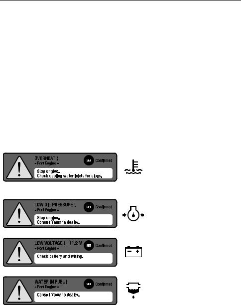
Alert Notifications
Follow the following instructions for responding to each specific alert. For further information, see page 11.
Overheat alert
Displayed when the engine temperature rises too high. Stop the engine and check the cooling water inlet.
Low oil pressure alert Displayed when the oil pressure drops too low. Stop the engine and consult a Yamaha dealer.
Low battery voltage alert Displayed when the battery voltage drops too low. Check the battery and battery connections.
Water in fuel alert
Displayed when water has accumulated in the water separator (fuel filter). Consult a Yamaha dealer.

Safety information
Engine trouble alert
Displayed when the engine malfunctions. Consult a Yamaha dealer.
Maintenance Notifications
Displayed when scheduled maintenance is overdue.
Carry out the maintenance and reset the maintenance schedule.
You can also specify individual maintenance intervals. For further information, see page 20.
Other Notifications
Displayed when an external memory (USB memory) is connected.
Displayed when water depth falls below a preset threshold. For further information, see page 6.
Displayed when water depth exceeds a preset threshold. For further information, see page 6.

List of abbreviations
List of abbreviations
The following are abbreviations displayed on this meter or used in this manual.
Abbreviation |
Description |
|
|
ABYC |
American Boat and Yacht Council |
|
|
AVAL |
Available fuel |
|
|
CL |
Command Link |
|
|
C PORT |
Center Port side |
|
|
C STBD |
Center Starboard side |
|
|
ECO, ECON |
Fuel Economy |
|
|
Eng |
Engine |
|
|
EUR |
Europe |
|
|
Ex. |
Exhaust |
|
|
F |
Forward |
|
|
FW |
Fresh Water tank |
|
|
GNRTR, GT |
Generator fuel tank |
|
|
GPS |
Global Positioning System |
|
|
INT |
Intake |
|
|
LAN |
Local Area Network |
|
|
Mfg./Dlr. |
Manufacturer/Dealer |
|
|
N |
Neutral |
|
|
NMEA |
National Marine Electronics Association |
|
|
No. |
Number |
|
|
Num. |
Number |
|
|
OPT |
Optional |
|
|
R |
Reverse |
|
|
R/C |
Remote Control |
|
|
STATS |
Status |
|
|
STD |
Standard |
|
|
SYNC |
Synchronization |
|
|
Temp |
Temperature |
|
|
TFT |
Thin Film Transistor |
|
|
USB |
Universal Serial Bus |
|
|
WASTE, WS |
Waste Water tank |
|
|
|
Table of contents/Specifications |
|
|
Table of contents |
|
Specifications......................................................................... |
|
1 |
Names and functions of parts............................................... |
2 |
|
Initialization ............................................................................ |
|
3 |
Meter display .......................................................................... |
|
7 |
Main screens....................................................................... |
|
7 |
Alert display ...................................................................... |
|
11 |
Condition display............................................................... |
|
12 |
Basic display ..................................................................... |
|
13 |
Specific selection .............................................................. |
|
15 |
Meter operation .................................................................... |
|
17 |
Switching the meter display .............................................. |
17 |
|
Menu screen ......................................................................... |
|
19 |
Operating the menu screen .............................................. |
19 |
|
Menu items and functions ................................................. |
20 |
|
Adjusting trolling engine speed ......................................... |
25 |
|
Trouble codes....................................................................... |
|
27 |
|
Specifications |
|
Field |
|
Specification |
Power source |
Rated voltage: 12 V |
|
|
Operating voltage range: 8–16 V |
|
Communications specificaInformation system LAN interface: |
||
tion |
The Multi-Display conforms to J1939-based Yamaha Net- |
|
|
work specifications. |
|
|
GPS Interface: |
|
|
The Multi-Display conforms to NMEA0183. |
|
Other interfaces |
Fuel sensor interface x 4 |
|
|
USB interface (Ver.1.1, 2.0) x 1 |
|
Display |
5-inch color TFT |
|
1
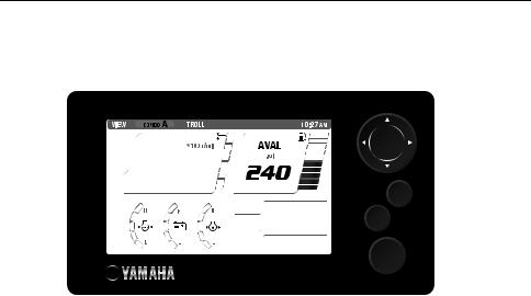
Names and functions of parts
Names and functions of parts
1
SET
CANCEL
MENU
2
3
4
5
6
|
Name |
Explanation of function |
1 |
Display |
Displays engine information, boat/environment information, |
|
|
setting menus, and so on. |
2 |
Directional keypad |
“LI” (Up/Down) buttons |
• Switches main screen
• Moves cursor (selects) on the menu screen
• Adjusts engine speed during trolling “HJ” (Left/Right) buttons
•Switches main screen
•Moves cursor (selects) on the menu screen
3 |
“SET” button |
• |
Set |
|
|
• |
Moves the menu screen cursor to the right |
|
|
• |
When on the main screen, moves to the “BRIGHTNESS” screen |
4 |
“CANCEL” button |
• |
Cancel |
|
|
• |
Moves from any setting screen to the menu screen |
|
|
• |
Moves from the menu screen to the main screen |
|
|
• |
Moves the menu screen cursor to the left |
|
|
• |
Cancels trolling mode |
|
|
• |
When on the main screen, moves to the “TRIP” screen |
5 |
“MENU” button |
• |
Moves from any screen to the top menu screen |
6 |
Status bar |
Displays the time and name of the main screen selected. |
|
|
|
Time will not be displayed if time information is not received |
|
|
|
from the network. |
|
2
Initialization
Initialization
The initialization screen is not normally displayed, except during installation.
TIP:
If it does appear, consult a Yamaha dealer.
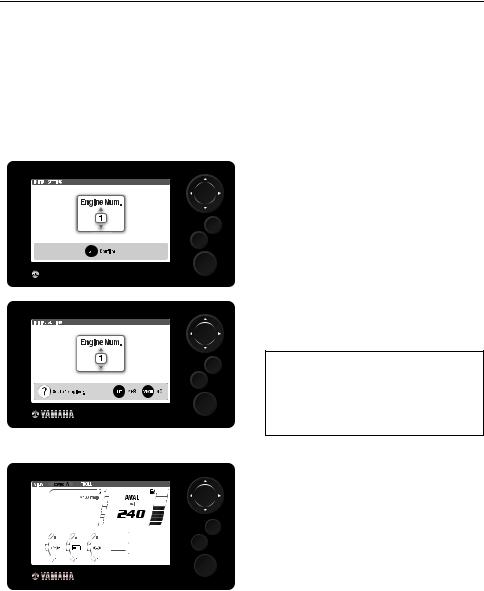
Configuring the number of outboard motors
1. Turn the engine switch to “ON.” The initialization screen is displayed.
SET
CANCEL
MENU
SET
CANCEL
MENU
SET
CANCEL
MENU
2.Use “LI” (Up/Down) buttons on the directional keypad to select the number of outboard motors on your boat.
1:Single-engine type
2:Twin-engine type
3:Triple-engine type
4P: Quadruple-engine type (PORT side) 4S: Quadruple-engine type (STBD side)
3.Set using the “SET” button.
4.The main screen is displayed.
3
Initialization
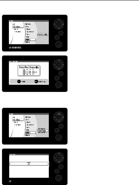
Configuring fuel tank parameters
1. Use the directional keypad and the “SET” button to display the “Fuel Capacity” in the menu screen.
SET
Fiel capacity
Tank Type
CANCEL
Factory Reset
MENU
2. Use the directional keypad to configure the total fuel capacity on your boat.
3. Set using the “SET” button.
SET
CANCEL
MENU
Configuring the tank sensors
1. Use the directional keypad and the “SET” button to display the “Tank Type” in the menu screen.
SET
CANCEL
MENU
2. Use the “HJ” (Left/Right) buttons on the directional keypad to select the “Tank No.”
3. Set using the “SET” button.
SET
CANCEL
MENU
4
Initialization
4. Use the directional keypad to select the sensor from the “Sensor” list.
5. Set using the “SET” button.
SET
CANCEL
MENU
Initializing trim angle
1. Fully trim the outboard motor down.
2. Use the directional keypad and the “SET” button to display the “Trim Level” in the menu screen.
SET
CANCEL
MENU
3. Check that the value displayed on the screen shows “0 %.”
SET
CANCEL
MENU
4. Use the “SET” button to reset the value if any value other than “0 %” is displayed.
SET
CANCEL
MENU
5
Loading...