


 Loading...
POWERED MONITOR SPEAKER


 HS80M/HS50M
SERVICE MANUAL


 ECF
ECF
PA 011806
HS80M: 200510-47250
HS50M: 200510-26250
■ CONTENTS |
|
HS80M SPECIFICATIONS ..................................... |
3 |
HS50M SPECIFICATIONS ..................................... |
4 |
DIMENSIONS ........................................................... |
5 |
PANEL LAYOUT ...................................... |
6 |
CIRCUIT BOARD LAYOUT .................. |
7 |
HS80M DISASSEMBLY PROCEDURE ................. |
8 |
HS50M DISASSEMBLY PROCEDURE ............... |
11 |
CIRCUIT BOARDS ........................................ |
14 |
HS80M INSPECTIONS ............................................... |
15 |
HS50M INSPECTIONS ............................................... |
16 |
BLOCK DIAGRAM |
|
OVERALL CIRCUIT DIAGRAM |
|
PARTS LIST |
|
HAMAMATSU, JAPAN
Copyright (c) Yamaha Corporation. All rights reserved. PDF 


 Printed in Japan ’05.12
HS80M/HS50M
IMPOR TANT NOTICE
This manual has been provided for the use of authorized Yamaha Retailers and their service personnel. It has been assumed that basic service procedures inherent to the industry, and more specifically Yamaha Products, are already known and understood by the users, and have therefore not been restated.
WARNING :
Failure to follow appropriate service and safety procedures when servicing this product may result in personal injury, destruction of expensive components and failure of the product to perform as specified. For these reasons, we advise all Yamaha product owners that all service required should be performed by an authorized Yamaha Retailer or the appointed service representative.
IMPORTANT :
This presentation or sale of this manual to any individual or firm does not constitute authorization, certification, recognition of any applicable technical capabilities, or establish a principal-agent relationship of any form.
The data provided is believed to be accurate and applicable to the unit (s) indicated on the cover. The research engineering, and service departments of Yamaha are continually striving to improve Yamaha products. Modifications are, therefore, inevitable and changes in specification are subject to change without notice or obligation to retrofit. Should any discrepancy appear to exist, please contact the distributor’s Service Division.
WARNING :
Static discharges can destroy expensive components. Discharge any static electricity your body may have accumulated by grounding yourself to the ground bus in the unit (heavy gauge black wires connect to this bus).
IMPORTANT :
Turn the unit OFF during disassembly and parts replacement. Recheck all work before you apply power to the unit.
WARNING: CHEMICAL CONTENT NOTICE!
The solder used in the production of this product contains LEAD. In addition, other electrical/electronic and/or plastic (Where applicable) components may also contain traces of chemicals found by the California Health and Welfare Agency (and possibly other entities) to cause cancer and/or birth defects or other reproductive harm.
DO NOT PLACE SOLDER, ELECTRICAL/ELECTRONIC OR PLASTIC COMPONENTS IN YOUR MOUTH FOR ANY REASON WHAT SO EVER!
Avoid prolonged, unprotected contact between solder and your skin! When soldering, do not inhale solder fumes or expose eyes to solder/flux vapor!
If you come in contact with solder or components located inside the enclosure of this product, wash your hands before handling food.
WARNING: THIS APPARATUS MUST BE EARTHED
IMPORTANT
T H E W I R E S I N T H I S M A I N S L E A D A R E C O L O U R E D I N ACCORDANCE WITH THE FOLLOWING CODE:
GREEN-AND-YELLOW : EARTH BLUE : NEUTRAL BROWN : LIVE
As the colours of the wires in the mains lead of this apparatus may not correspond with the coloured markings identifying the terminals in your plug, proceed as follows:
The wire which is coloured GREEN and YELLOW must be connected to the terminal in the plug which is marked by the letter E or by the safety earth symbol or coloured GREEN and YELLOW.
The wire which is coloured BLUE must be connected to the terminal which is marked with the letter N or coloured BLACK.
The wire which is coloured BROWN must be connected to the terminal which is marked with the letter L or coloured RED.
*This applies only to products distributed by YAMAHA KEMBLE MUSIC (U.K.) LTD.
■WARNING
Components having special characteristics are marked  and must be replaced with parts having specification equal to those originally installed.

2
HS80M/HS50M
HS80M
■ HS80M SPECIFICATIONS
General specifications
Type ................................................ |
Biamp 2-way Powered speaker |
Crossover Frequency ..................... |
2 kHz |
Overall Frequency Response ......... |
42 Hz-20 kHz (-10 dB) |
Dimensiones (W x H x D)............... |
250 x 390 x 332 mm (9-13/16” x 15-3/8” x 13-1/6”) |
Weight ............................................ |
11.3 kg |
Speaker Components
Speaker Components .................... |
LF: 8" Cone (Magnetic shielding Type) |
|
HF: 1" Dome (Magnetic shielding Type) |
Enclosure ....................................... |
Type: Bass-reflex Type |
|
Material: MDF |
Amp. unit
Output Power .................................. |
Total: 120 W (dynamic power) |
|
(LF: 75 W, 4 ohms, 1 kHz) |
|
(HF: 45 W, 8 ohms, 10 kHz) |
Input Sensitivity/Impedance ........... |
-10 dBu/ 10 k-ohms |
Input Connectors (parallel) ............ |
1: XLR-3-31 type (balanced) |
|
2: PHONE (balanced) |
Controls .......................................... |
LEVEL control (+4 dB/ center click) |
|
LOW CUT switch (FLAT/ 80/ 100 Hz, 12 dB/ octave) |
|
MID EQ switch (+/- 2 dB at 2 kHz) |
|
HIGH TRIM switch (+/- 2 dB at HF) |
|
ROOM CONTROL switch (0/ -2/ -4 dB under 500 Hz) |
Power Indicator .............................. |
Power ON: White LED |
Power Consumption ....................... |
60 W |
●
................................................ |
2 |
................... |
2 kHz |
.............................. |
42 Hz 20 kHz -10 dB |
W×H×D .............. |
250×390×332 mm |
................................................ |
11.3 kg |
●
....................... |
LF 20 cm |
|
HF 2.5 cm |
........................... |
|
|
MDF |
●
......................................... |
120 W |
|
LF 75 W 4 ohms 1 kHz |
|
HF 45 W 8 ohms 10 kHz |
/ ............... |
-10 dBu/ 10 k-ohms |
....................... |
1 XLR-3-31 |
|
2 |
.................................. |
LEVEL +4 dB/ center click |
|
LOW CUT FLAT/ 80/ 100 Hz 12 dB/ octave |
|
MID EQ +/- 2 dB at 2 kHz |
|
HIGH TRIM +/- 2 dB at HF |
|
ROOM CONTROL 0/-2/-4 dB under 500Hz |
.............................. |
ON LED |
......................................... |
60 W |
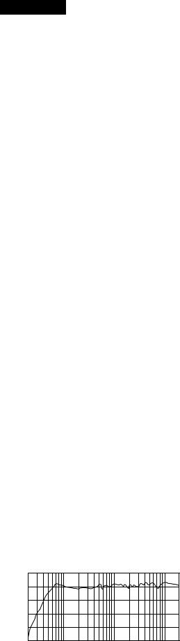
• Performance graph
RESPONSE (dB)
+10
0
-10
-20
-30
-40
20 |
100 |
1k |
10k |
FREQUENCY (Hz)
3

HS80M/HS50M
HS50M
■ HS50M SPECIFICATIONS
General specifications
Type ................................................ |
Biamp 2-way Powered speaker |
Crossover Frequency ..................... |
3 kHz |
Overall Frequency Response ......... |
55 Hz-20 kHz (-10 dB) |
Dimensiones (W x H x D) ............... |
165 x 268 x 222 mm (6-1/2” x 10-9/16” x 8-3/4”) |
Weight ............................................ |
5.8 kg |
Speaker Components
Speaker Components .................... |
LF: 5" Cone (Magnetic shielding Type) |
|
HF: 0.75" Dome (Magnetic shielding Type) |
Enclosure ....................................... |
Type: Bass-reflex Type |
|
Material: MDF |
Amp. unit
Output Power .................................. |
Total: 70 W (dynamic power) |
|
(LF: 45 W, 4 ohms, 1 kHz) |
|
(HF: 25 W, 8 ohms, 10 kHz) |
Input Sensitivity/Impedance ........... |
-10 dBu/ 10 k-ohms |
Input Connectors (parallel) ............ |
1: XLR-3-31 type (balanced) |
|
2: PHONE (balanced) |
Controls .......................................... |
LEVEL control (+4 dB/ center click) |
|
LOW CUT switch (FLAT/ 80/ 100 Hz, 12 dB/ octave) |
|
MID EQ switch (+/- 2 dB at 2 kHz) |
|
HIGH TRIM switch (+/- 2 dB at HF) |
|
ROOM CONTROL switch (0/ -2/ -4 dB under 500 Hz) |
Power Indicator .............................. |
Power ON: White LED |
Power Consumption ....................... |
45 W |
●
................................................ |
2 |
................... |
3 kHz |
.............................. |
55 Hz 20 kHz -10 dB |
W×H×D .............. |
165×268×222 mm |
................................................ |
5.8 kg |
●
....................... |
LF 13 cm |
|
HF 2.0 cm |
........................... |
|
|
MDF |
●
......................................... |
70 W |
|
LF 45 W 4 ohms 1 kHz |
|
HF 25 W 8 ohms 10 kHz |
....................... |
1 XLR-3-31 |
|
2 |
.................................. |
LEVEL +4 dB/ center click |
|
LOW CUT FLAT/ 80/ 100 Hz 12 dB/ octave |
|
MID EQ +/- 2 dB at 2 kHz |
|
HIGH TRIM +/- 2 dB at HF |
|
ROOM CONTROL 0/-2/-4 dB under 500Hz |
.............................. |
ON LED |
......................................... |
45 W |
• Performance graph
RESPONSE (dB)
+10
0
-10
-20
-30
-40
20 |
100 |
1k |
10k |
FREQUENCY (Hz)
4
HS80M/HS50M
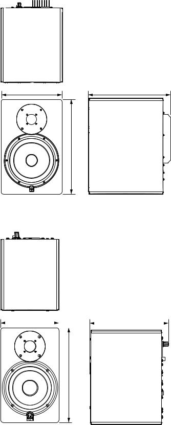
■ DIMENSIONS
• HS80M
250 (9-13/16") |
332 (13-1/16") |
390 (15-3/8")
Unit: mm (inch)
mm
• HS50M
165 (6-1/2") |
|
|
222 (8-3/4") |
||
|
|||||
|
|
|
|
|
|
268 (10-9/16")
Unit: mm (inch)
mm
5
HS80M/HS50M
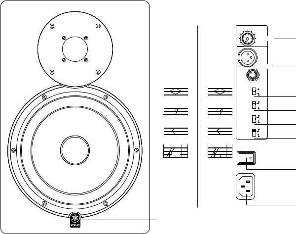
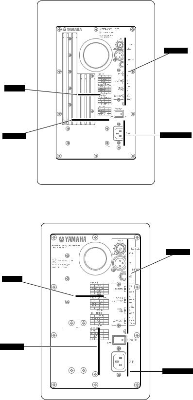
■ PANEL LAYOUT
+4dB
LEVEL
MIN
 -10dB
-10dB
1
INPUT
|
HS80M |
HS50M |
|
|
|
|
2 |
|||||||||||
MID EQ |
MID EQ |
|
|
|
|
|
|
|||||||||||
|
0dB |
+2dB |
|
|
0dB |
|
+2dB |
|
|
MID EQ |
|
|
|
+2dB |
||||
|
|
|
|
|
|
|
|
|
|
|
|
|
|
|
0 |
|||
|
|
-2dB |
|
|
|
|
-2dB |
|
|
|
|
|
|
|
-2dB |
|||
|
|
|
|
|
|
|
|
|
|
|
|
|
|
|||||
|
|
2kHz |
|
|
|
2kHz |
|
|
|
|
|
0 |
||||||
ROOM CONTROL |
ROOM CONTROL |
ROOM |
|
|
|
|||||||||||||
|
0dB |
|
|
|
0dB |
|
|
|
|
CONTROL |
|
|
|
-2dB |
||||
|
|
|
|
|
|
|
|
|
|
-4dB |
||||||||
|
-2dB |
|
|
|
-2dB |
|
|
|
|
|
|
|
|
|
||||
|
-4dB |
|
|
|
-4dB |
|
|
|
|
|
|
|
|
|
+2dB |
|||
|
|
|
|
|
|
|
|
|
|
|
|
|
HIGH |
|
|
|
|
|
|
|
500Hz |
|
|
500Hz |
TRIM |
|
|
|
|
0 |
|||||||
HIGH TRIM |
HIGH TRIM |
|
|
-2dB |
||||||||||||||
|
|
+2dB |
|
|
|
|
+2dB |
|
|
|
|
|
|
|
FLAT |
|||
|
|
|
|
|
|
|
|
|
|
|
|
|
|
|
|
|
|
|
|
0dB |
|
|
|
0dB |
|
|
|
|
|
|
|
|
|
||||
|
|
|
|
|
|
|
|
|
|
|
|
|
LOW CUT |
|
|
80Hz |
||
|
|
-2dB |
|
|
|
|
-2dB |
|
|
|
|
|
|
|
100Hz |
|||
|
|
2kHz |
|
|
3kHz |
|
|
|
|
|
|
|||||||
LOW CUT |
LOW CUT |
|
|
|
|
|
|
|||||||||||
|
FLAT |
|
|
FLAT |
|
|
|
|
|
|
|
|
|
|
||||
|
80Hz |
|
80Hz |
|
|
|
|
|
|
|
|
|
|
|||||
|
|
|
|
|
|
|
|
|
|
|
|
|
|
|
|
|||
|
|
100Hz |
|
|
100Hz |
|
|
|
|
|
|
|
||||||
POWER
OFF |
ON |
AC IN
9
1 |
POWER switch |
1 |
POWER |
2 |
LEVEL control |
2 |
LEVEL |
3 |
INPUT 1, 2 connector |
3 |
INPUT 1 2 |
4 |
MID EQ switch |
4 |
MID EQ |
5 |
ROOM CONTROL switch |
5 |
ROOM CONTROL |
6 |
HIGH TRIM switch |
6 |
HIGH TRIM |
7 |
LOW CUT switch |
7 |
LOW CUT |
8 |
AC IN Connector |
8 |
AC IN |
9 |
Power indicator |
9 |
Power |
2
3
4
5
6
7
1
8
6
HS80M/HS50M
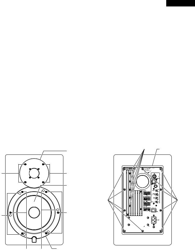
■ CIRCUIT BOARD LAYOUT
• HS80M
INPUT
(LF 3/4)
AMP
(LF 2/4)
TRANS |
AC INLET |
(LF 4/4) |
(LF 1/4) |
• HS50M
INPUT
(LF 3/4)
AMP
(LF 2/4)
TRANS
(LF 4/4)
AC INLET
(LF 1/4)
7
HS80M/HS50M
HS80M
■ HS80M DISASSEMBLY PROCEDURE
1.Woofer (Time required: about 1 minute)
1-1 Remove the six (6) screws marked [55]. The woofer ring can then be removed. (Fig. 1)
1-2 Remove the six (6) screws marked [40]. The woofer can then be removed. (Fig. 1)
2.Tweeter (Time required: about 1 minute)
Remove the four (4) screws marked [20]. The tweeter can then be removed. (Fig. 1)
3.Rear Panel Assembly (Time required: about
1 minute)
Remove the ten (10) screws marked [155]. The rear panel assembly can then be removed. (Fig. 2)
4.AMP Circuit Board
(Time required: about 2 minutes)
4-1 Remove the rear panel assembly.(See procedure 3.) 4-2 Remove the five (5) screws marked [90]. The AMP
unit can then be removed. (Fig. 2)
*At this time, be careful not to lose the spacer which also comes off.
Tweeter
[20] |
[20] |
|
Woofer |
|
|
[55]
[40]
1.1
1-1 55 61
1-2 40 6 1
2.1
20 41
3.Ass’y 1
155 10 Ass’y2
4.AMP 2
4-1 Ass’y 3
4-2 90 5 AMP
2
[90]
Rear Panel Assembly
Ass'y
[155] |
[155] |
|
[55] |
[40] |
Woofer Ring |
|
|
|
|
||
|
|
|
|
|
|
|
Fig. 1 1 |
|
Fig. 2 2 |
[20]: |
Hexagonal Socket Tapping Screw 4x20 (WG341100) 6 |
[90]: Bind Head Tapping Screw-S 3x16 (WG341600) |
||
|
TP1 |
|
|
S |
[40]: |
Bind Head Tapping Screw 4x16 (WG540200) |
[155]: Bind Head Tapping Screw 4x16 (WG540200) |
||
|
TP1 |
|
|
TP1 |
[55]: |
Hexagonal Socket Tapping Screw 4x20 (WG341100) 6 |
|
||
|
TP1 |
|
|
|
8

|
|
|
|
|
|
|
|
HS80M/HS50M |
|
HS80M |
|
|
|
|
|
||
4-3 Unsolder soldered parts (22 locations) on the pat- |
4-3 |
IC801 IC802 22 |
||||||
|
tern side of IC801 and IC802. (Photo. 1) |
|
1 |
|||||
4-4 Remove the two (2) screws marked [A] and remove |
4-4 |
A 2 IC801 IC802 |
||||||
|
the heat sink with IC801 and IC802. (Photo. 1) |
|
1 |
|||||
|
Remove the two (2) screws marked [B] and remove |
|
B 2 IC801 IC802 |
|||||
|
IC801 and IC802. (Photo. 1) |
|
|
1 |
||||
4-5 Remove the four (4) screws marked [C], remove the |
4-5 |
C 4 AMP AMP |
||||||
|
AMP mounting bracket. The AMP circuit board can |
|
1 |
|||||
|
then be removed. (Photo. 1) |
|
|
|
||||
|
|
|
|
|
[A] |
|
|
|
|
|
|
|
|
|
AMP mounting BRACKET |
|
|
|
HEAT SINK |
|
|
|
|
AMP |
|
|
|
|
|
|
|
|
|
||
|
|
IC802 |
[C] |
|
CASE PWB |
|||
|
SPACER |
|
|
|
PWB |
|||
|
IC801 |
|
|
|
||||
|
|
|
|
|||||
|
|
|
|
|||||
AMP mounting BRACKET |
|
|
|
|
||||
|
AMP |
|
|
|
INPUT Circuit Board |
|||
|
|
|
|
|
|
|
|
|
|
|
[B] |
|
|
|
INPUT |
||
|
|
|
|
|
|
|||
|
|
|
|
|
|
AMP circuit board |
|
|
|
[C] |
|
AMP |
|
|
|||
|
|
|
|
|
||||
|
|
|
|
|
Photo. 1 1 |
|
|
Photo. 2 2 |
|
|
|
|
|
<AMP Unit> |
|
|
<INPUT Assembly> |
|
|
|
|
|
AMP |
|
|
Input Ass’y |
5. INPUT Circuit Board |
|
5. |
INPUT 3 |
|||||
|
(Time required: about 3 minutes) |
5-1 |
Ass’y 3 |
|||||
5-1 Remove the rear panel assembly. (See procedure 3.) |
5-2 |
110 4 115 1 |
||||||
|
|
|||||||
5-2 Remove the four (4) screws marked [110] and the |
|
3 |
||||||
|
|
|||||||
|
screw marked [115]. (Fig. 3) |
|
5-3 LEVEL E D |
|||||
|
|
|
|
|||||
5-3 Remove the LEVEL knob, the hexagonal nut [E] and |
|
3 5 |
||||||
|
|
|||||||
|
washer [D]. (Fig. 3, Photo. 5) |
|
5-4 F |
|||||
|
|
|
|
|||||
5-4 Remove the hexagonal nut [F] on the phone type in- |
|
INPUT Ass’y 5 |
||||||
|
|
|||||||
|
put connector. The INPUT assembly can then be re- |
5-5 G 3 PWB INPUT |
||||||
|
|
|
||||||
|
moved. (Photo. 5) |
|
|
3 |
||||
|
|
|
|
|||||
5-5 Remove the three (3) screws marked [G] and remove |
|
PWB INPUT |
||||||
|
|
|||||||
the case PWB. (Photo. 3) |
|
|
|
The Input circuit board can then be removed. |
|
|
*The case PWB is not a component of the INPUT circuit board. When replacing the INPUT circuit board, remove the case PWB and reuse it.
[G]
Photo. 3 3 |
9 |
|
Loading...