


 Loading...
HD CAMCORDER
HDW-730 HDW-750 HDW-750P
OPERATION MANUAL [English] 1st Edition (Revised 1)

WARNING
To prevent fire or shock hazard, do not expose the unit to rain or moisture.
To avoid electrical shock, do not open the cabinet. Refer servicing to qualified personnel only.
AVERTISSEMENT
Afin d’éviter tout risque d’incendie ou d’électrocution, ne pas exposer cet appareil à la pluie ou à l’humidité.
Afin d’écarter tout risque d’électrocution, garder le coffret fermé. Ne confier l’entretien de l’appareil qu’à un personnel qualifié.
WARNUNG
Um Feuergefahr und die Gefahr eines elektrischen Schlages zu vermeiden, darf das Gerät weder Regen noch Feuchtigkeit ausgesetzt werden.
Um einen elektrischen Schlag zu vermeiden, darf das Gehäuse nicht geöffnet werden. Überlassen Sie Wartungsarbeiten stets nur qualifiziertem Fachpersonal.
For the customers in USA
This equipment has been tested and found to comply with the limits for a Class B digital device, pursuant to Part 15 of the FCC Rules. These limits are designed to provide reasonable protection against harmful interference in a residential installation. This equipment generates, uses, and can radiate radio frequency energy and, if not installed and used in accordance with the instructions, may cause harmful interference to radio communications. However, there is no guarantee that interference will not occur in a particular installation. If this equipment does cause harmful interference to radio or television reception, which can be determined by turning the equipment off and on, the user is encouraged to try to correct the interference by one or more of the following measures:
—Reorient or relocate the receiving antenna.
—Increase the separation between the equipment and receiver.
—Connect the equipment into an outlet on a circuit different from that to which the receiver is connected.
—Consult the dealer or an experienced radio/TV technician for help.
You are cautioned that any changes or modifications not expressly approved in this manual could void your authority to operate this equipment.
The shielded interface cable recommended in this manual must be used with this equipment in order to comply with the limits for a digital device pursuant to Subpart B of Part 15 of FCC Rules.
For the customers in Europe
This product with the CE marking complies with the EMC Directive (89/336/EEC) issued by the Commission of the European Community.
Compliance with this directive implies conformity to the following European standards:
•EN55103-1: Electromagnetic Interference (Emission)
•EN55103-2: Electromagnetic Susceptibility (Immunity) This product is intended for use in the following Electromagnetic Environment(s):
E1 (residential), E2 (commercial and light industrial), E3 (urban outdoors) and E4 (controlled EMC environment, ex. TV studio).
Pour les clients européens
Ce produit portant la marque CE est conforme à la Directive sur la compatibilité électromagnétique (EMC) (89/ 336/CEE) émise par la Commission de la Communauté européenne.
La conformité à cett directive implique la conformité aux normes européennes suivantes:
•EN55103-1: Interférences électromagnétiques (émission)
•EN55103-2: Sensibilité électromagnétique (immunité) Ce produit est prévu pour être utilisé dans les environnements électromagnétiques suivants:
E1 (résidentiel), E2 (commercial et industrie légère), E3 (urbain extérieur) et E4 (environnement EMC contrôlé, ex. studio de télévision).
Für Kunden in Europa
Dieses Produkt besitzt die CE-Kennzeichnung und erfüllt die EMV-Direktive (89/336/EEC) der EG-Kommission. Die Erfüllung dieser Direktive bedeutet Konformität für die folgenden Europäischen Normen:
•EN55103-1: Elektromagnetische Interferenz (Emission)
•EN55103-2: Elektromagnetische Empfindlichkeit (Immunität)
Dieses Produkt ist für den Einsatz unter folgenden elektromagnetischen Bedingungen ausgelegt:
E1 (Wohnbereich), E2 (kommerzieller und in beschränktem Maße industrieller Bereich), E3 (Stadtbereich im Freien) und E4 (kontrollierter EMVBereich, z.B. Fernsehstudio)

Table of Contents
Chapter 1 Overview
1-1 |
Features ..................................................................................... |
1-1 |
|
|
1-1-1 |
Camera Features ............................................................... |
1-1 |
|
1-1-2 |
VTR Features .................................................................... |
1-4 |
1-2 |
Precautions ................................................................................ |
1-7 |
|
1-3 |
Example of System Configuration .......................................... |
1-8 |
|
Chapter 2 Locations and Functions of Parts
and Controls
2-1 |
Power Supply ............................................................................ |
2-1 |
2-2 |
Accessory Attachments ............................................................ |
2-3 |
2-3 |
Audio Functions ........................................................................ |
2-5 |
2-4 Shooting and Recording/Playback Functions ...................... |
2-14 |
|
2-5 |
Menu Operating Section ........................................................ |
2-29 |
2-6 |
Time Code System .................................................................. |
2-33 |
2-7 |
Warnings and Indications ...................................................... |
2-39 |
2-8 Warnings and Indications on the Display Panel .................. |
2-42 |
|
2-9 Indicators on the Viewfinder ................................................. |
2-46 |
|
Chapter 3 Recording and Playback
3-1 |
About Cassettes ......................................................................... |
3-1 |
|
|
3-1-1 Loading and Unloading a Cassette .................................. |
3-1 |
|
|
3-1-2 |
Preventing Accidental Erasure ........................................ |
3-5 |
3-2 |
Recording .................................................................................. |
3-6 |
|
|
3-2-1 |
Basic Procedures ............................................................. |
3-6 |
|
3-2-2 |
Continuous Recording ................................................... |
3-12 |
|
3-2-3 Recording Good Shot Markers ...................................... |
3-15 |
|
|
3-2-4 Recording a Recording Start Marker ............................ |
3-20 |
|
|
3-2-5 |
Starting a Shoot with a Few Seconds of Pre-Stored |
|
|
|
Picture Data (Loop Rec Function) (When Using an |
|
|
|
HKDW-703 Extension Board) ...................................... |
3-20 |
|
|
(Continued) |
|
|
|
Table of Contents |
1 |

|
3-2-6 Shooting Pictures at Intervals (Interval Rec Function) |
|
|
|
|
(When Using an HKDW-703) ...................................... |
3-28 |
|
3-2-7 |
Continuous Recording on the Previous Cut .................. |
3-52 |
|
3-2-8 |
Searching for the Last Recorded Portion and Turning |
|
|
|
in the Recording Pause Mode (End Search Function) .. |
3-53 |
3-3 |
Checking the Recording — Playback ................................... |
3-55 |
|
|
3-3-1 |
Checking the Last Two Seconds of the Recording |
|
|
|
— Recording Review .................................................... |
3-55 |
|
3-3-2 |
Checking the Recording on the Color Video Monitor |
|
|
|
— Playback in Color ..................................................... |
3-56 |
3-4 |
Recording the Recording Start Time Code onto |
|
|
|
the Memory Label — Tele-File ............................................. |
3-58 |
|
3-5 |
Freezing a Picture during Playback ..................................... |
3-63 |
|
3-6 |
Setting the Stand-by off Timer During Rec-Pause .............. |
3-66 |
|
Chapter 4 Adjustments and Settings for Recording
4-1 Adjusting the Black Balance and the White Balance |
............ 4-1 |
||
|
4-1-1 Adjusting the Black Balance ........................................... |
4-2 |
|
|
4-1-2 Adjusting the White Balance .......................................... |
4-6 |
|
4-2 |
Setting the Electronic Shutter ............................................... |
4-12 |
|
|
4-2-1 |
Shutter Modes ............................................................... |
4-12 |
|
4-2-2 Selecting the Shutter Mode and Speed .......................... |
4-14 |
|
4-3 |
Changing the Reference Value for Automatic Iris |
|
|
|
Adjustment .............................................................................. |
4-21 |
|
4-4 |
Adjusting the Audio Level ..................................................... |
4-28 |
|
4-5 |
Setting the Time Data ............................................................. |
4-36 |
|
|
4-5-1 Setting the Time Code ................................................... |
4-36 |
|
|
4-5-2 |
Saving the Real Time in the Time Code ....................... |
4-38 |
|
4-5-3 |
Setting the User Bits ...................................................... |
4-39 |
|
4-5-4 |
Synchronizing the Time Code ....................................... |
4-41 |
2 Table of Contents

4-6 Menu Display on the Viewfinder Screen .............................. |
4-46 |
4-6-1 Menu Configuration ...................................................... |
4-46 |
4-6-2 Basic Use of the Menu .................................................. |
4-49 |
4-6-3 Editing the USER Menu ................................................ |
4-55 |
4-7 Status Display on the Viewfinder Screen ............................. |
4-64 |
4-7-1 Layout of the Status Display on the Viewfinder |
|
Screen ............................................................................ |
4-65 |
4-7-2 Selecting the Display Items ........................................... |
4-70 |
4-7-3 Display Mode and Setting Change and Adjustment |
|
Progress Messages ........................................................ |
4-73 |
4-7-4 Setting the Marker Display ........................................... |
4-75 |
4-7-5 Setting the Viewfinder .................................................. |
4-78 |
4-7-6 Recording Superimposed Shot Data in Color Bars ....... |
4-81 |
4-7-7 Setting the Shot ID ........................................................ |
4-84 |
4-7-8 Displaying the Status Confirmation Windows .............. |
4-90 |
4-7-9 Confirming the Image of the Return Video Signal |
|
on the Viewfinder .......................................................... |
4-94 |
4-8 Adjustments and Settings from Menus ................................ |
4-98 |
4-8-1 Setting the GAIN Selector Values ................................ |
4-98 |
4-8-2 Selecting the Output Signals ....................................... |
4-101 |
4-8-3 Setting the Color Temperature Manually .................... |
4-104 |
4-8-4 Specifying an Offset for the Auto White Balance |
|
Setting ......................................................................... |
4-106 |
4-8-5 Assigning Functions to ASSIGN 1/2 Switches ........... |
4-109 |
4-8-6 Setting the Date/Time of the Internal Clock ............... |
4-114 |
4-8-7 Selecting the Lens File ................................................ |
4-116 |
4-9 Saving/Loading User Menu Data to/from |
|
Memory Stick ........................................................................ |
4-118 |
4-9-1 Handling the Memory Stick ........................................ |
4-118 |
4-9-2 Saving/Loading User Menu Data to/from |
|
Memory Stick .............................................................. |
4-122 |
4-10 Resetting USER Menu Settings to the Standard |
|
Settings ................................................................................... |
4-133 |
(Continued) |
|
Table of Contents |
3 |

4-11 |
Using the Scene Files ............................................................ |
4-135 |
|
4-11-1 Storing Data in the Scene File ..................................... |
4-135 |
|
4-11-2 Loading Scene Files .................................................... |
4-145 |
|
4-11-3 Resetting the Settings of the Camcorder to |
|
|
the Standard Settings Saved in the Reference File ...... |
4-150 |
4-12 |
Jumping to a File-Related Menu Page When Inserting |
|
|
a Memory Stick ..................................................................... |
4-151 |
Chapter 5 Setting Up the Camcorder
5-1 |
Power Supply ............................................................................ |
5-1 |
|
|
5-1-1 Using a Battery Pack ....................................................... |
5-1 |
|
|
5-1-2 Avoiding Breaks in Operation Due to Dead Batteries .... |
5-4 |
|
|
5-1-3 Using an AC Adaptor ...................................................... |
5-5 |
|
|
5-1-4 Using the Anton Bauer Ultralight System ...................... |
5-6 |
|
5-2 |
Adjusting the Viewfinder ......................................................... |
5-7 |
|
|
5-2-1 Adjusting the Viewfinder Position .................................. |
5-7 |
|
|
5-2-2 Adjusting the Viewfinder Focus and Screen ................... |
5-9 |
|
|
5-2-3 |
Detaching the Viewfinder ............................................. |
5-10 |
|
5-2-4 |
Detaching the Eyepiece ................................................. |
5-12 |
5-3 |
Mounting the Lens .................................................................. |
5-14 |
|
5-4 |
Adjusting the Flange Focal Length ....................................... |
5-15 |
|
5-5 |
Audio Input System ................................................................ |
5-17 |
|
|
5-5-1 Using the Supplied Microphone .................................... |
5-17 |
|
|
5-5-2 Using an External Microphone ..................................... |
5-19 |
|
|
5-5-3 Attaching a UHF Portable Tuner (for a UHF Wireless |
|
|
|
|
Microphone System) ..................................................... |
5-24 |
|
5-5-4 Connecting Line Input Audio Equipment ..................... |
5-28 |
|
5-6 |
Tripod Mounting .................................................................... |
5-29 |
|
5-7 |
Attaching the Shoulder Strap ................................................ |
5-31 |
|
5-8 |
Adjusting the Shoulder Pad Position .................................... |
5-33 |
|
5-9 |
Putting On the Rain Cover .................................................... |
5-34 |
|
5-10 Connecting the Remote Control Unit ................................... |
5-36 |
||
4 Table of Contents

Chapter 6 Maintenance
6-1 |
Testing the Camcorder Before Shooting |
................................ 6-1 |
|
|
6-1-1 |
Preparations for Testing .................................................. |
6-1 |
|
6-1-2 |
Testing the Camera ......................................................... |
6-2 |
|
6-1-3 |
Testing the VTR .............................................................. |
6-5 |
6-2 |
Maintenance ............................................................................ |
6-11 |
|
|
6-2-1 Cleaning the Video Heads ............................................. |
6-11 |
|
|
6-2-2 |
Cleaning the Viewfinder ............................................... |
6-11 |
6-3 |
Operation Warnings ............................................................... |
6-14 |
|
Appendix
Specifications ..................................................................................... |
A-1 |
Video Camera Section ............................................................... |
A-2 |
VTR Section .............................................................................. |
A-3 |
Supplied Accessories ................................................................. |
A-6 |
Recommended Additional Equipment ...................................... |
A-6 |
Menu List ........................................................................................... |
A-9 |
OPERATION Menu List ........................................................... |
A-9 |
PAINT Menu List .................................................................... |
A-19 |
MAINTENANCE Menu List .................................................. |
A-31 |
FILE Menu List ....................................................................... |
A-46 |
DIAGNOSIS Menu List .......................................................... |
A-49 |
About a “Memory Stick” ................................................................ |
A-50 |
Index .................................................................................................... |
I-1 |
Table of Contents |
5 |
1-1 Features
The HDW-730/750/750P 1) HD Camcorder combines an HD color video camera, of which the effective picture elements are 1920(H) × 1080(V) and which uses 2/3-type Power HAD 2) sensor CCD 3) imagers with 2,000,000 picture elements, with an HDCAM portable videocassette recorder. Its excellent image quality, sensitivity, portability, and dustand water-proof construction make it ideal as a camcorder for ENG 4) and EFP 5) in the same way as the earlier BVW-400A/400AP. The introduction of a new integrated circuit technology (LSI) for processing HD digital signals improves the image quality even further and simplifies setup (initialization) operations.
1-1-1 Camera Features
The features of the HDW-730/750/750P camera are described below.
•2/3-type Power HAD sensor CCDs with 2,000,000 picture elements provide a compact and lightweight unit with excellent image quality. The HDW-750/750P uses FIT 6)-type CCDs and the HDW-730 uses IT 7)-type CCDs.
•Existing 2/3-inch lenses can be used.
•A new integrated circuit technology for digital signal processing has improved picture quality and functionability.
•A setup menu enables you to control features such as status displays, messages, and markers; to select various types of settings; to toggle
switches; and to operate a Memory Stick 8).
....................................................................................................................................
1)The HDW-730 can operate with either the 59.94I or the 50I format. The HDW750 operates with the 59.94I format. The HDW-750P can operate with either the 50I or the 25PsF format. The descriptions given in this manual apply to all models, any differences being clearly noted in the text.
2)Power HAD: Power Hole-Accumulated Diode
“Power HAD” is a registered trademark of Sony Corporation.
3)CCD: Charge-Coupled Device
4)ENG: Electronic News Gathering
5)EFP: Electronic Field Production
6)FIT: Frame Interline Transfer
7)IT: Interline Transfer
8)“Memory Stick” is a trademark of Sony Corporation.
Chapter 1 Overview 1-1
1
Overview

1 |
• Blur-free shooting is ensured by a built-in, high-performance electronic |
shutter that provides a variety of modes, such as ECS 1) mode which |
reduces flickering on the monitor screen, and EVS 2) mode for the HDW-730 and S-EVS 3) mode for the HDW-750/750P 4) which improve vertical resolution.
• Selectable video gain ensures a noise-free image.
• A simple switch operation enables automatic adjustment of the black set, black balance, and white balance. Memory functions make it easy to replicate the white balance setting appropriate for the lighting conditions.
• The ATW 5) function automatically adjusts the white balance for the varying lighting conditions during shooting.
• The “TruEye” 6) process is used to ensure naturally colored pictures even when shooting very bright subject.
• The video gain can be boosted to 42 dB instantly using the TURBO GAIN button.
• Character display functions on the viewfinder indicate switch settings, automatic black and white balance adjustment, status indications, and warnings.
• The warning system uses various types of warning indicators and sounds to inform you of VTR faults, end of tape, low battery, etc.
• The camcorder is equipped with a dual-wheel filter disk for adjusting the filter setting to the shooting and lighting conditions.
• Override function which makes fine adjustment of the reference value for brightness of automatic iris control is provided.
....................................................................................................................................
1)ECS: Extended Clear Scan
2)EVS: Enhanced Vertical definition System
3)S-EVS: Super Enhanced Vertical definition System
4)When the HDW-750P operates with the 25PsF format, neither S-EVS mode nor EVS mode is availabele
5)ATW: Auto Tracing White balance
6)TruEye: “TruEye” is a registered trademark of Sony Corporation.
1-2 Chapter 1 Overview
• A built-in circuit produces a color bar signal for easy adjustment of the |
|
1 |
color monitor. |
|
|
•The RM-B150 remote control unit (not supplied) controls camera functions and VTR functions.
•Setup data made on the USER menu, including the various marker settings, can be stored on a Memory Stick as a user file. After storage, it can be recalled.
•Setup data specified by video engineers, including the various detail settings, can be stored in the camcorder itself and on a Memory Stick as a reference file. After storage it can be loaded. This makes it possible to shorten setup time by duplicating the stored reference file to other cameras through the Memory Stick.
•Setup data specified by video engineers, including the video settings, can be stored in the camcorder itself and on a Memory Stick as a scene file. This makes it possible to load setup data appropriate for the scene.
•Correction values for lens extenders and individual lenses can be stored as a lens file. The values can then be recalled. This makes it possible to shorten adjustment time when the lens is replaced.
•A high-performance viewfinder is adjustable forward, backward, and sideways, and has a full range of auxiliary equipment.
•The camcorder is provided with the XLR 5-pin connector, which allows connection of a stereo microphone. The ASSIGN 1/2 switches allow microphone mode to be switched between stereo and monaural.
•The HD SDI output (corresponding to Embedded Audio) makes it possible to monitor the camera image and playback image.
•Attaching an HKDW-702 down converter (not supplied) (converting to a 525i/625i signal 1)) allows the camera image and playback image to be monitored on an NTSC/PAL monitor. This board makes it possible to output the SDI signal (corresponding to Embedded Audio).
....................................................................................................................................
1)When an HKDW-702 is attached to an HDW-750 or an HDW-730 which operates with the 59.94I format, the HD signal is down-converted to a 525i signal. When an HKDW-702 is attached to an HDW-750P or an HDW-730 with the 50I format, the HD signal is down-converted to a 625i signal.
Chapter 1 Overview 1-3

1 • Three down converter modes are available: SQUEEZE, LETTER BOX and CROP.
• The camcorder is provided with the LIGHT connector. This feeds power to the light from a battery or AC adaptor connected to the camcorder.
• The viewfinder supplied with NTSC/PAL type camcorders, such as the BVW-400A/400AP, can be attached to HDW-730/750/750P in emergencies (only when an HKDW-702 (not supplied) is attached). Some functions are not available with this viewfinder.
• The camcorder has the ASSIGN 1/2 switches, which can be assigned functions.
1-1-2 VTR Features
The VTR features of this camcorder are described below.
• Use of the HDCAM format allows high performance HD digital recording and playback while preserving the same ease of use as conventional camcorder equipment.
• The same cassette size (S size) as Digital BETACAM can be used to achieve a long recording time of approximately 40 minutes (for 59.94I format) and 48 minutes (for 50I/25PsF format).
• No playback adaptor is needed to see the color playback image on the monitor screen.
• The 4 times normal speed search function provides quick positioning of the tape.
• LTC 1) and VITC 2) recording and LTC playback can be performed.
• It is possible to record recording start markers and good shot markers on the tape while shooting, and search automatically for required cuts when editing.
....................................................................................................................................
1)LTC: Longitudinal Time Code
2)VITC: Vertical Interval Time Code
1-4 Chapter 1 Overview

• It is possible to automatically rewind and review the last 2 seconds of |
1 |
the recording on the tape for a quick check immediately after shooting. |
•Compatible with the Tele-File 1) Memory Label system.
By pressing the RET button on the lens while recording, the timecode valid when you pressed the button is recorded on a MLB-1M-100 memory label (not supplied) attached to the cassette. This is very helpful for management of the cassette tapes and to improve the efficiency of the tape editing.
•The built-in time code generator can be synchronized with an external generator.
•A lithium battery is the back-up power supply for the built-in time code generator enabling the time code to be held for approximately 5 years without charging the camcorder power supply.
•Optional long-life battery packs are available.
•Pressing the VTR START button on the camcorder or the VTR button on the lens ensures recording continuity from the very next frame.
•The time code is displayed in the LCD window screen even when the power is off. The automatic power shut-off function has three time code indication settings.
•The camcorder continuously stores a few seconds of the most recent picture data. Recording is started with this data when the REC button is pressed. This prevents the loss of picture data (Loop Rec function). (This feature is available when an HKDW-703 (not supplied) is attached.)
•The camcorder can shoot pictures at intervals. (This feature is available when an HKDW-703 (not supplied) is attached.)
•A slot-in UHF portable tuner WRR-855A/855B (not supplied) can be attached.
....................................................................................................................................
1)Tele-File
The Tele-File system is a non-contact data reading/writing system. It allows a variety of data to be stored on a 1/2-inch tape label with an non-contact IC memory.
Chapter 1 Overview 1-5

1 • Four channels of analog audio can be converted to 20-bit digital signals. The converted four channels of digital audio can then be recorded.
• Connecting an HDCA-901 camera adaptor (not supplied) allows the input of four audio channels. This also makes it possible for the HDSDI signal to be output.
• When connecting the audio cable to AUDIO IN CH-1/CH-2 connectors (XLR 3-pin), the audio signals input to the XLR 3-pin are recorded regardless of the AUDIO IN switch setting. This function is called the XLR connection automatic detection function.
• The AUDIO OUT connector (XLR 5-pin) allows the camcorder to output signals from two channels at the same time (stereo recording).
• The camcorder searches for the most recently recorded cut and records the new cut over it. (RE-TAKE function)
• The camcorder searches for the point most recently recorded on the tape and automatically switches to paused recording mode (rec pause). (End Search function)
• The camcorder can record GPS data with the video data on the tape. (This feature is available when an HKDW-704 GPS UNIT is attached.)
1-6 Chapter 1 Overview
1-2 Precautions
Use and Storage |
|
1 |
|
||
|
|
|
Do not subject the camcorder to severe shocks
The internal mechanism may be damaged or the body warped.
After use
Always turn off the power.
Before storing the camcorder for a long period
Remove the battery pack.
Use and storage locations
Store in a level, ventilated place. Avoid using or storing the camcorder in the following places.
•Places subject to temperature extremes
•Very damp places
•Places subject to severe vibration
•Near strong magnetic fields
•In direct sunlight or close to heaters for extended periods
To prevent electromagnetic interference from portable communications devices
The use of portable telephones and other communications devices near this unit can result in misoperations and interference with audio and video signals.
It is recommended that the portable communications devices near this unit be powered off.
Note on laser beams
Laser beams may damage the CCDs. If you shoot a scene that includes a laser beam, be careful not to let a laser beam become directed into the lens of the camera.
Chapter 1 Overview 1-7

|
1-3 |
Example of System Configuration |
|
|
|||
1 |
The diagram below shows a typical configuration of the camcorder for |
For more information about the fittings, connections, or use of additional |
|||||
ENG and EFP. |
|
|
equipment and accessories, see Chapter 5 as well as the operation manuals for |
||||
|
|
|
the connected equipment. |
|
|||
|
|
|
|
|
|
||
|
Viewfinder-related equipment |
|
|
|
|
|
|
|
|
|
|
|
|
|
Lens assembly b) (−2.8 D to +2.0 D) |
|
Fog-proof filter |
|
|
Camera adaptor |
|
(Part No. A-8262-537-A) |
|
|
(Part No. 1-547-341-11) |
|
Video monitor for |
HDCA-901 for the input of |
Lens assembly b) (−3.6 D to −0.8 D) |
||
|
|
|
BKDW-701 |
(Part No. A-8262-538-A) |
|||
|
|
|
color image check |
the audio channels 3 and |
|||
|
|
BKW-401 Viewfinder |
Servo filter unit |
Lens assembly b) (−3.6 D to +0.4 D) |
|||
|
|
4 and the HD-SDI output |
|||||
|
|
Rotation Bracket |
|
while shooting |
(Part No. A-8267-737-A) |
||
|
|
|
|
|
|
|
Lens assembly b) |
|
|
|
|
|
|
|
(3 × magnification) |
|
|
|
|
|
|
|
(−2.4 D to +0.5 D) |
|
|
|
|
|
|
|
(Part No. A-8314-798-A) |
|
Extension |
|
|
|
|
Audio signal source |
|
|
|
|
Power source |
|
|||
|
board |
|
|
External microphone |
|||
|
|
|
|
|
|
Battery |
|
|
HKDW-703 for |
|
|
|
C-74, etc. |
||
|
|
|
|
|
|||
|
picture cache |
|
|
AC power |
BC-L120/M50 |
CAC-12 Microphone |
|
|
HKDW-702 a) for |
Memory Stick |
supply c) |
Battery |
|||
|
converting the signal |
|
Charger |
Holder |
|||
|
to 525i/625i signal |
|
|
|
|
||
|
|
|
|
|
Audio equipment |
||
|
HKDW-704 for |
|
|
AC-550/ |
|
||
|
|
|
BP-L60A/ |
|
|||
|
recording the GPS |
Remote controll |
|
||||
|
550CE |
|
|||||
|
M50/M100 |
WRR810A/860A/862A/ |
|||||
|
data |
equipment |
|||||
|
AC Adaptor |
||||||
|
Battery Pack |
862B UHF Portable Tuner |
|||||
|
|
|
|
|
|||
|
|
|
|
|
|
||
|
|
|
RM-B150 Remote |
AC-DN2B |
|
WRR-855A/855B slot- |
|
|
|
|
Control Unit |
|
|||
|
|
|
|
in UHF portable tuner |
|||
|
|
|
AC Adaptor |
|
|||
|
|
|
|
|
|
||
|
|
|
|
|
|
|
|
|
|
|
|
|
|
|
CCXA-53 audio cable |
a)Be sure to attach the HKDW-702/1 or higher to the HDW-730/750P.
b)For more information, see “Viewfinder and related equipment” on page A-7.
c)120 V AC or 220 to 240 V AC
1-8 Chapter 1 Overview
2-1 |
Power Supply |
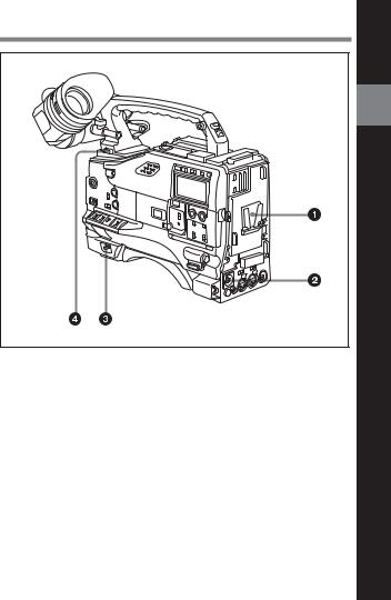
Power supply
1 Battery attachment
Attach a BP-L60A/M50/M100 battery pack.
Furthermore, by attaching an AC-DN2B AC Adaptor, you can operate the camcorder from AC power.
2 DC IN (external power input) connector (XLR type, 4-pin, male)
To operate the HDW-730/750/750P using an AC power supply, connect an AC-550/550CE AC Adaptor with the DC output cable supplied with the adaptor.
To use an external battery, connect its DC output cable to the DC IN connector.
Chapter 2 Locations and Functions of Parts and Controls |
2-1 |
2
Controls and Parts of Functions and Locations

3 POWER switch
This switch turns the main power supply on and off.
2 4 LIGHT switch
This switch selects the way in which a video light connected to the LIGHT connector is switched on and off.
AUTO: When the video light switch is turned on, starting recording with the VTR turns on the light.
MANUAL: The video light switch controls the light, turning it on and off manually.
2-2 Chapter 2 Locations and Functions of Parts and Controls
2-2 |
Accessory Attachments |
|
2 |
|
Lens cable clamp |
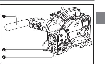
Accessory attachments
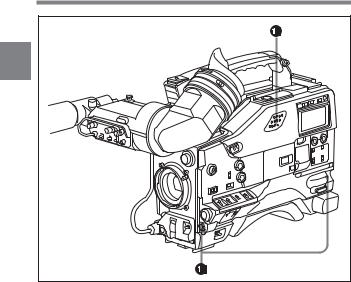
1 Shoulder strap posts
Attach the supplied shoulder strap to these posts.
2 Light shoe
Attach an optional accessory such as a video light to this shoe.
Chapter 2 Locations and Functions of Parts and Controls |
2-3 |

|
3 LIGHT connector (2-pin, female) |
|
|
Connect the cable of the Anton Bauer Ultralight System attached to the |
|
|
light shoe. The system operates with lights powered by 12 V, with a |
|
2 |
||
maximum power consumption of 50 W. |
||
|
|
4 Lens mount (special bayonet mount)
Use this for mounting the lens.
5 Lens locking lever
After inserting the lens in the lens mount, rotate the lens mount ring with this lever to lock the lens in position.
6 Lens mount cap
Remove this cap by pushing up on the lens locking lever. For protection from dust, always insert this cap when no lens is mounted.
7 LENS connector (12-pin)
Fit the lens cable to this connector. Contact your Sony representative for more information about the lens you are using.
8 Tripod mount
When using the unit on a tripod, attach the supplied tripod adaptor.
9 Shoulder pad
You can move the shoulder pad forwards or backwards by loosening the two screws. Do this to ensure the best balance when shooting with the camcorder on your shoulder.
Note
Do not remove screws instead of loosening them. If you have removed them, be sure to use the screws you removed, or screws of the same length (8 mm). If you fasten the shoulder pad using longer screws, they may damage parts inside the unit.
2-4 Chapter 2 Locations and Functions of Parts and Controls
2-3 |
Audio Functions |
|
2 |
Audio functions (1)
1 Microphone
This is a super-cardioid directional stereo microphone with an external power supply (+48 V) system.
If you assign the Front MIC MONO/STEREO function to either ASSIGN 1 or 2 switch, you can switch the monaural and stereo outputs.
2 MIC IN (microphone input) connector (XLR type, 5-pin, female)
You can connect a supplied stereo microphone with an external power supply system. The connector supplies power (+48 V) to the microphone.
3 MIC LEVEL knob
This knob adjusts the audio level of the microphone connected to the MIC IN connector.
Chapter 2 Locations and Functions of Parts and Controls |
2-5 |
2 |
Audio functions (2)
2-6 Chapter 2 Locations and Functions of Parts and Controls

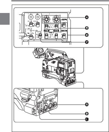
4LEVEL (CH-1/CH-2) (audio channel 1 and channel 2 recording level) controls
These controls adjust the audio levels of channels 1 and 2 when audio
input is from the AUDIO IN CH-1/CH-2 connectors and the AUDIO 2 SELECT switches are set to MANUAL.
5 AUDIO SELECT (CH-1/CH-2) (audio channel-1 and channel-2 adjustment method select) switches
These switches select the audio level adjustment method for each of audio channels 1 and 2.
AUTO: Select this setting for automatic adjustment. MANUAL: Select this setting for manual adjustment.
6AUDIO IN CH-1/CH-2 / CH-3/CH-4 (audio input select) switches
AUDIO IN CH-1/CH-2 switches
These switches select the audio input signals to be recorded for audio channels 1 and 2.
FRONT: The input signal source is the microphone connected to the MIC IN connector.
REAR: The input signal source is the audio equipment connected to the AUDIO IN CH-1/CH-2 connectors.
WIRELESS: The input signal source is a WRR-855A/855B UHF Synthesized Tuner Unit (not supplied).
CH-3/CH-4 switches
These switches select the audio input signals to be recorded for audio channels 3 and 4.
Note
To activate CH-3/CH-4 switches, set AUDIO CH3/4 MODE to SW on the VTR MODE 1 page of the MAINTENANCE menu.
F (FRONT): The input signal source is the microphone connected to the MIC IN connector.
R (REAR): The input signal source is the audio equipment connected to the AUDIO IN CH-1/CH-2 connectors.
Chapter 2 Locations and Functions of Parts and Controls |
2-7 |

W (WIRELESS): The input signal source is a WRR-855A/855B UHF Synthesized Tuner Unit (not supplied).
With the HDCA-901 (not supplied) connected to the camcorder, you can 2 record separate sounds in audio channels 3 and 4.
For detailed information, see “When the HDCA-901 camera adaptor is used” on page 4-35.
7 CUE IN (cue track input) switch
This switch selects the input signal to be recorded on the cue track. CH-1: Signal selected by the AUDIO IN CH-1 switch 6
MIX: Mixed signals selected by the AUDIO IN CH-1 and CH-2 switches 6
CH-2: Signal selected by the AUDIO IN CH-2 switch 6
8 AUDIO OUT (audio output) connector (XLR type, 5-pin, male)
This connector outputs the audio signals recorded to audio channels 1 and 2 or audio channels 3 and 4.
The MONITOR CH-1/2 / CH-3/4 switches qd allow you to select the audio signal to be played back.
Using a CCXA-53 Audio Cable (not supplied), you can convert from a 5-pin connection to two 3-pin connections.
9AUDIO IN CH-1/CH-2 (audio channel 1 and channel 2 input) connectors (XLR type, 3-pin, female) and LINE/MIC/+48 V ON (line input/microphone input/external power supply +48 V ON) switches
These are audio input connectors for channels 1 and 2 to which you can connect audio equipment or a microphone.
The LINE/MIC/+48V ON switches select the audio source of the audio input signals connected to each of these connectors.
LINE: Line input audio equipment
MIC: Microphone with an internal power supply
+48V ON: Microphone with an external power supply system
0 DC OUT (DC power output) connector
This connector supplies power for a WRR-810A/860A/862A/862B UHF Portable Tuner (not supplied). Do not connect any equipment other than the UHF portable tuner.
2-8 Chapter 2 Locations and Functions of Parts and Controls
2 |
Audio functions (3)
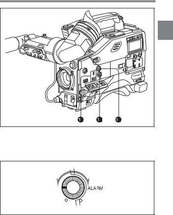
qa ALARM volume control
This control adjusts the speaker or earphone alarm volume. At the minimum position, no sound can be heard.
Minimum Maximum
ALARM volume control
Chapter 2 Locations and Functions of Parts and Controls |
2-9 |
The internal volume control can be adjusted so that the alarm is audible even if the ALARM volume control is at the minimum position.
For more information, refer to the Maintenance Manual (not supplied).
2
qs MONITOR volume control
This control adjusts the speaker or earphone volume for sounds other than the alarm sound. At the minimum position, no sound can be heard.
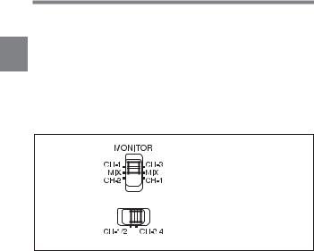
qd MONITOR (audio channel select) switch /CH-1/2 / CH-3/4 (audio channel 1/2 / audio channel 3/4 select) switch
MONITOR switch
CH-1/2 / CH-3/4 switch
MONITOR switch and CH-1/2 / CH-3/4 switch
CH-1/2 / CH-3/4 switch
This switch decides the audio channel to be selected by the MONITOR switch.
CH-1/2: Audio channels 1 and 2 CH-3/4: Audio channels 3 and 4
The following settings depend on the CH-1/2 / CH-3/4 switch setting:
•The signal output to the AUDIO OUT connector 8 is switched. CH-1/2: Audio channels 1 and 2
CH-3/4: Audio channels 3 and 4
•The audio signal indicated by the audio level meter in the display window is switched.
2-10 Chapter 2 Locations and Functions of Parts and Controls

MONITOR switch
This switch selects the audio output to the speaker or earphone.
|
|
|
|
2 |
CH-1/2 CH-3/4 |
MONITOR switch |
Audio output |
||
position |
position |
|
|
|
|
|
|
|
|
CH-1/2 |
CH-1 |
Audio channel 1 |
|
|
|
|
|
|
|
|
MIX |
Mix sound of channels 1 and 2 |
|
|
|
|
|
|
|
|
CH-2 |
Audio channel 2 |
|
|
|
|
|
|
|
CH-3/4 |
CH-3 |
Audio channel 3 |
|
|
|
|
|
|
|
|
MIX |
Mix sound of channels 3 and 4 |
|
|
|
|
|
|
|
|
CH-4 |
Audio channel 4 |
|
|
|
|
|
|
|
Chapter 2 Locations and Functions of Parts and Controls 2-11
2 |
Audio functions (4)
qf Built-in speaker
During recording, the speaker can be used for monitoring the E-E 1) sound, and during playback for monitoring playback sound. The speaker also sounds alarms to reinforce visual warnings.
If an earphone is plugged into to the EARPHONE jack, the speaker sound is automatically cut off.
See “6-3 Operation Warnings” on page 6-14 for information about alarms.
....................................................................................................................................
1)E-E sound (Electric-to-Electric sound)
The term E-E sound refers to an audio signal that has passed through the amplifier, but has not been recorded on the tape. In other words, you can directly monitor the recording input signal, as opposed to the simultaneous playback (output) signal.
2-12 Chapter 2 Locations and Functions of Parts and Controls
Loading...