

Yamaha DGX-620, YPG-625 Service manual
/
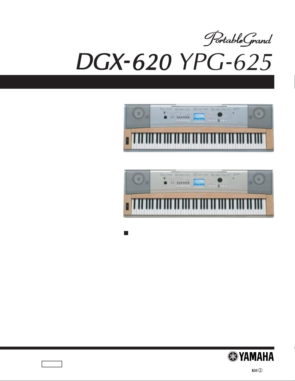
SERVICE MANUAL
DGX-620
YPG-625
CONTENTS
SPECIFICATIONS .................................................................... 3
PANEL LAYOUT........................................................................ 4
CIRCUIT BOARD LAYOUT & WIRING ..................................... 6
BLOCK DIAGRAM .................................................................... 8
DISASSEMBLY PROCEDURE ................................................. 9
LSI PIN DESCRIPTION .......................................................... 20
IC BLOCK DIAGRAM.............................................................. 23
CIRCUIT BOARDS ................................................................. 24
TEST PROGRAM ................................................................... 33
INITIALIZATION ...................................................................... 37
USER DATA BACKUP ............................................................. 38
MIDI IMPLEMENTATION CHART ........................................... 42
MIDI DATA FORMAT ............................................................... 43
PA RTS LIST
OVERALL CIRCUIT DIAGRAM
PK 001760
HAMAMATSU, JAPAN
Copyright (c) Yamaha Corporation. All rights reserved. PDF ’06.03
DGX-620/YPG-625
p
p
IMPORTANT NOTICE
This manual has been provided for the use of authorized Yamaha Retailers and their service personnel. It has been assumed that
basic service procedures inherent to the industry, and more specifically Yamaha Products, are already known and understood by the
users, and have therefore not been restated.
WARNING:
IMPORTANT:
The data provided is believed to be accurate and applicable to the unit(s) indicated on the cover. The research engineering, and
service departments of Yamaha are continually striving to improve Yamaha products. Modifications are, therefore, inevitable
and changes in specification are subject to change without notice or obligation to retrofit. Should any discrepancy appear to
exist, please contact the distributor's Service Division.
WARNING:
IMPORTANT:
Failure to follow appropriate service and safety procedures when servicing this product may result in personal injury, destruction of expensive components and failure of the product to perform as specified. For
these reasons, we advise all Yamaha product owners that all service required should be performed by an
authorized Yamaha Retailer or the appointed service representative.
This presentation or sale of this manual to any individual or firm does not constitute authorization certification, recognition of any applicable technical capabilities, or establish a principal-agent relationship of
any form.
Static discharges can destroy expensive components. Discharge any static electricity your body may have
accumulated by grounding yourself to the ground bus in the unit (heavy gauge black wires connect to
this bus.)
Turn the unit OFF during disassembly and parts replacement. Recheck all work before you apply power to
the unit.
WARNING: CHEMICAL CONTENT NOTICE!
The solder used in the production of this product contains LEAD. In addition, other electrical/electronic and/or plastic (Where
applicable) components may also contain traces of chemicals found by the California Health and Welfare Agency (and possibly
other entities) to cause cancer and/or birth defects or other reproductive harm.
DO NOT PLACE SOLDER, ELECTRICAL/ELECTRONIC OR PLASTIC COMPONENTS IN YOUR MOUTH FOR ANY REASON
WHAT SO EVER!
Avoid prolonged, unprotected contact between solder and your skin! When soldering, do not inhale solder fumes or expose eyes to
solder/flux vapor!
If you come in contact with solder or components located inside the enclosure of this product, wash your hands before handling food.
WARNING
Components having special characteristics are marked and must be replaced with parts having specification equal to those
originally installed.
SAVING DATA
Saving and backing up your data
The panel settings and some other types of data are not retained in memory when you turn off the power to the
instrument. Save data you want to keep to the Registration Memory.
Saved data may be lost due to malfunction or incorrect operation.
Be sure to
erform it
Save important data to a USB storage device/or other external device such as a computer.
Backing up the USB storage device/external media
To protect against data loss through media damage, we recommend that you save your important data onto two
USB storage devices/external media.
Be sure to
erform it
2

■ SPECIFICATIONS
Keyboards
• 88 Graded Hammer Standard keys (A-1–C7), with Touch
Response.
Display
• 320 x 240 dots LCD display (backlit)
Setup
• STANDBY/ON
• MASTER VOLUME: MIN–MAX
• LCD CONTRAST
Panel Controls
• SONG, VOICE, STYLE, EASY SONG ARRANGER,
P.A.T. ON/OFF, LESSON L, LESSON R, LESSON START,
METRONOME ON/OFF, PORTABLE GRAND, DEMO,
FUNCTION, MUSIC DATABASE, HARMONY ON/OFF,
DUAL ON/OFF, SPLIT ON/OFF, TEMPO/TAP, [0]–[9], [+],
[-], CATEGORY, Dial, REPEAT & LEARN (ACMP ON/OFF),
A-B REPEAT (INTRO/ENDING/rit.), PAUSE (SYNC START),
START/STOP, REW (MAIN/AUTO FILL), FF (SYNC STOP),
REGIST MEMORY ([MEMORY/BANK], [1], [2]),
SONG MEMORY (REC, [1]–[5], [A]), File Control [MENU],
File Control [EXECUTE], [EXIT], [LYRICS], [SCORE],
[CHORD FINGERING]
Realtime Control
• Pitch Bend Wheel
Voice
• 127 panel voices + 12 drum/SFX kits + 361 XGlite voices
• Polyphony: 32
• DUAL
• SPLIT
Style
• 150 Preset Styles + 1 User Style File
• Style Control: ACMP ON/OFF, SYNC STOP, SYNC START,
START/STOP, INTRO/ENDING/rit.,
MAIN/AUTO FILL
• Fingering: Multi Finger, Full Keyboard
• Style Volume
Music Database
• 267
Education Feature
• Dictionary
• Lesson 1–3, Repeat & Learn
Registration Memory
•8 banks x 2 types
Function
• VOLUME: Style Volume, Song Volume
• OVERALL: Tuning, Transpose, Split Point, Touch Sensitiv-
ity, Pitch Bend Range, Chord Fingering
• MAIN VOICE: Volume, Octave, Pan, Reverb Level,
Chorus Level
• DUAL VOICE: Volume, Octave, Pan, Reverb Level,
Chorus Level
• SPLIT VOICE: Volume, Octave, Pan, Reverb Level,
Chorus Level
• EFFECT: Reverb Type, Chorus Type, Master EQ Type,
Sustain
• HARMONY: Harmony Type, Harmony Volume
• Performance assistant technology:
Performance assistant technology Type
• PC: PC Mode
• MIDI: Local On/Off, External Clock, Initial Send,
Keyboard Out, Style Out, Song Out
• METRONOME: Time Signature Numerator, Time Signature
Denominator, Metronome Volume
• SCORE: Quantize
• LESSON: Lesson Track (R), Lesson Track (L), Grade
• UTILITY: Demo Cancel, Language
DGX-620/YPG-625
Effects
• Reverb: 9 types
• Chorus: 4 types
• Harmony: 26 types
Song
• 30 Preset Songs + 5 User Songs + Accessory CD-ROM Songs (70)
• Song Clear, Track Clear
• Song Volume
• Song Control: REPEAT & LEARN, A-B REPEAT, PAUSE,
Performance assistant technology
• Chord, Chord/Free, Melody, Chord/Melody
Recording
• Song
User Song: 5 Songs
Recording Tracks: 1, 2, 3, 4, 5, STYLE
MIDI
• Local On/Off • Initial Send • External Clock
• Keyboard Out • Style Out • Song Out
Auxiliary jacks
• PHONES/OUTPUT, DC IN 12V, USB TO HOST,
USB TO DEVICE, SUSTAIN
Ampli er
• 6W + 6W
Speakers
• 12cm x 2 + 3cm x 2
Power Consumption
• 22W
Power Supply
• Adaptor: Yamaha PA-5D AC power adaptor
Dimensions (W x D x H)
••1,398 x 457 x 153 mm (55-1/16" x 18" x 6")
with keyboard stand:
1,405 x 485 x 773 mm (55-1/3" x 19-1/8" x 30-3/8")
Weight
••18.0kg (39 lbs. 11 oz.)
with keyboard stand:
25.5kg (56 lbs. 3 oz.)
Supplied Accessories
•
Music Rest • Accessory CD-ROM
•
Keyboard Stand • Owner’s Manual • Footswitch FC5
•
AC Power adaptor (May not be included depending on your particular area.)
Optional Accessories
• Headphones: HPE-150
REW, FF, START/STOP
3
DGX-620/YPG-625
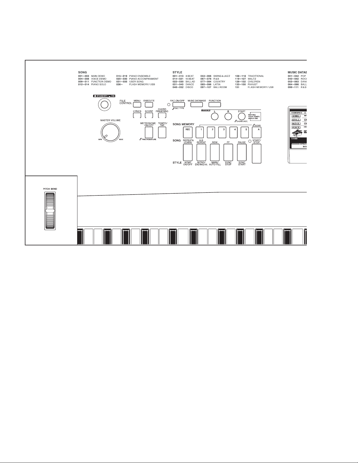
■ PANEL LAYOUT
• Front Panel
#4
q
w
e
r t y
!1 !2
u i o
!4 !5
!0
!3
!6 !7 !8 !9
• Front Panel
[STANDBY/ON] switch
q
[MASTER VOLUME control
w
e FILE CONTROL [MENU], [EXECUTE] button
[LYRICS] button
r
[SCORE] button
t
y [CHORD FINGERING] button
u [P.A.T. ON/OFF] button
i [MUSIC DATABASE] button
o
[FUNCTION] button
!0
LESSON [L],[R], [START] buttons
[METRONOME ON/OFF] button
!1
[TEMPO/TAP] button
!2
SONG MEMORY [REC], [1]-[5], [A] buttons
!3
[REPEAT & LEARN]/ [ACMP ON/OFF] button
!4
!5 [A-B REPEAT]/[INTRO/ENDING/rit.] button
[REW]/[MAIN/AUTO FULL] button
!6
!7 [FF]/[SYNC STOP] button
[PAUSE]/[SYNC START] button
!8
[START/STOP] button
!9
[SONG] button
@0
@1 [EASY SONG] ARRANGER] button
@2 [STYLE] button
@3 [VOICE] button
4
DGX-620/YPG-625
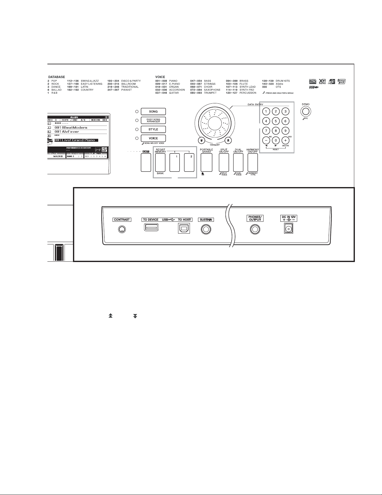
Rear Panel
@0
@1
@2
@3
@8
@9
#5 #6 #7 #8 #9
@4
@5
#0 #1 #2 #3
@6
@7
@4 Dial
@5 CATEGORY[ ] and [ ] buttons
@6 Number buttons [0]–[9],[+] and [-] buttons
[DEMO] button
@7
[EXIT] button
@8
REGIST MEMORY [MEMORY/BANK], [1], [2] buttons
@9
[PORTABLE GRAND] button
#0
[SPLIT ON/OFF] button
#1
[DUAL ON/OFF] button
#2
[HARMONY ON/OFF] button
#3
[PITCH BEND] wheel
#4
• Rear Panel
CONTRAST knob
#5
USB TO DEVICE, TO HOST terminals
#6
SUSTAIN jack
#7
PHONES/OUTPUT jack
#8
DC IN 12V jack
#9
5
DGX-620/YPG-625
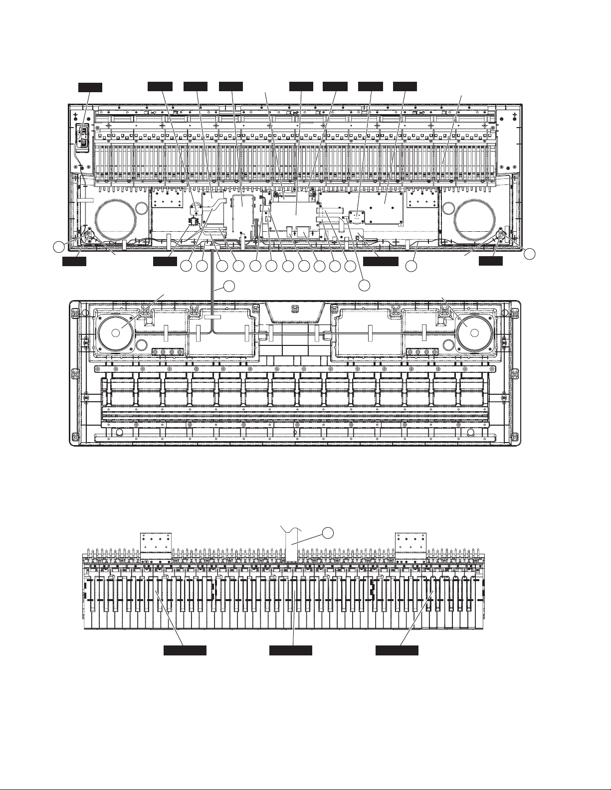
■ CIRCUIT BOARDS LAYOUT & WIRING
• Upper case
PB
MVR
PNL
AM
LCD unit
DM ENC PNR
MKO
Keyboard assembly
< Bottom view >
15
TW (L)
Speaker
(Tweeter (L))
PSW
• Lower case
• Keyboard assembly
< Top view >
13
10
Speaker
(Woofer (L))
15
7
9
12
3
8
1
6
2
5
5
4
DJACK
14
11
(Tweeter (R))
Speaker
(Woofer (R))
Speaker
TW (R)
GHL88L GHL88M GHL88H
6
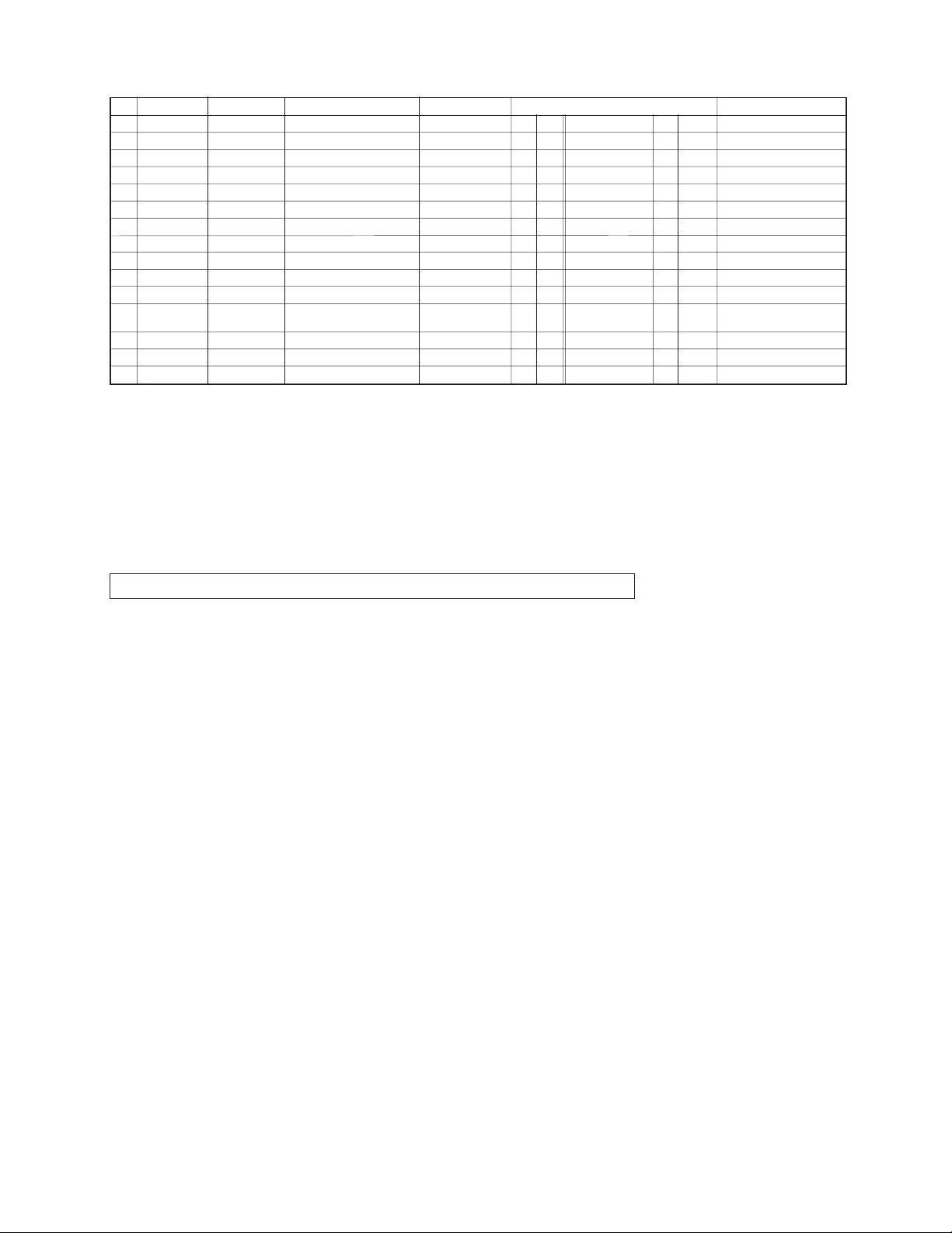
No.
Location Part No. Connector Assembly Destination Remarks
q
w
e
r
t
y
u
i
o
!0
!1
!2
!3
!4
!5
-- -- Flexible flat cable
240 WG317700
230 DM-CN601 *1 *4 PNL-CN01 *1 *4 12P
250 DM-CN602 *1 *4 PNR-CN02 *1 *4 15P
2 DM-CN701 *1 *4
260 DM-CN901 *1 *4 AM-CN104 *1 *4 19P
WG317600
WG317800
WG318100
WG317900
WH501 (WG45930) AM-CN101 *1 *5 PSW-CN501 *2 *5 4P
290 WB092100 AM-CN102 *1 *5 LCD *3 *6 2P
WH401 (WG46060) AM-CN103 *1 *5 PB-CN401 *2 *5 3P
WH201 (WG46040)
WH202 (WG46050)
Flexible flat cable
Flexible flat cable
Flexible flat cable
Flexible flat cable
Flexible flat cable
PSW
BL
PB
TWL
TWR
30 (WG45880) SP2 AM-CN203 *1 *9
WH601 (WG46070) MVR
WH901 (WB09270)
ENC PNR-CN03 *1 *5 ENC-CN901 *2 *5 3P
DM-CN201 *1 *4 LCD *3 *4 14P
DM-CN301 *1 *4 DJACK-CN301 *1 *4 14P
GHL88M-CN02
*1 *4 27P
AM-CN201 *2 *5 TW(L) *3 *6 2P
AM-CN202 *2 *5 TW(R) *3 *6 2P
Speaker Lch
Speaker Rch
*9
*3
*10
*3
AM-CN204 *1 *5 MVR-CN601 *2 *5 5P
-- -- -- Speaker *11 -- TW *3 *10 2P
* The parts with "( )" in "Part No." are not available as spare parts.
* 1 : Installation
* 2 : Dip soldering
* 3 : Manual soldering
* 4 : The conductor of a cable and the point of contact of a connector are untited.
* 5 : Edge mark is adjusted to Pin 1 (왕) side.
* 6 : Edge mark is connected to + side.
* 7 : Edge mark is connected to + terminal.
* 8 : White wire is adjusted to Pin 1 (왕) side.
* 9 : White wire is connected to + terminal.
* 10 : Red wire is connected to + terminal.
* 11 : Connected
Caution: Be sure to attach the removed filament tape just as it was before removal.
DGX-620/YPG-625
4P
X0159A00
7
8
USB
DATA ENTRY
ENC
ROTARY
ENCODER
CN901(3P)
CN03(3P)
SW
MATRIX
LED
PNR
PNL
SW
MATRIX
LED
EC901
IN[0-6]
PA[4-7]
IN[0-6]
PA[0-3]
CN02(15P)
CN01(12P)
DJACK
DM
+5D
IC102 (5P)
RESET
5
3.6V
16.9344
MHz
X101
PB0-7
TA601-604
CN602(15P)
LED
DRIVER
CR701
5MHz
CPU
IC701 (44P)
uPD789022GB
CN601(12P)
Keyboard(GHL)
88KEY
with touch response
GHL88L
SUSTAIN
JK301
4
12,13
PA0-7
+5D
R704
18,3814,15
16
27
22
TO DEVICE
JK303
6MHz
X301
+3.3D
20
PD3
*A
ICN
*A:24,47,66,90,120
*B:15,46,89,119
PD1,2
YMW767-V
RXD1
TXD1 SD0
38
CONTROLLER
+3.3D
56,58
+2.5D
*B
CPU
IC101
(128P)
37 40
CN701(27P)
B[1-15]
N[11-16]
N[21-26]
GHL88M
TO HOST
JK302
CN301(14P)
CN301(14P)
ISP1161A
USB
IC301
(64P)
MA/MD
SDI
+5D
+3.3D
37
38
41
BCLK, WCLK
SYSCLK, BCLK, WCLK
CN2(27P)
CONTRAST
VR301
+29V
DC/DC
CONVERTER
IC202
(8P)
MA0-23
MD0-15
128M
ROM
PROG
/WAVE
IC802(48P)
+21~27V
7,12,22,25
32,40,48,55
+3.3D
37
FLASH
ROM
IC803(48P)
GHL88H
+3.3D
8M
IC501(10P)
PCM1742K
2
IC401(16P)
BACK LIGHT
LCD
DISPLAY
320 X 240
STN
CN201(14P)
LCDC
IC201
(64P)
S1D13700F00A
+3.3D
1,6
16M
25
DRAM
IC804(50P)
ADC
8bit
14
DAC
24bit
XD0-3
YD,LP
XCSL,WF
CS0:128M ROM
CS1:LCDC
CS3:8M FLASH
CS5:USBC
+3.3D
2
PITCH BEND
+5A
7
826
IC402(8P)
LPF
+3.3D
+2.5D
+5A
8
17L
R
IC902 (3P)
+3.3V
REG.
+2.5V
REG.
IC901 (3P)
+5D
+5A
MVR
+5D
CN901(19P)
CN104(19P)
VR601
MASTER
VOLUME
PB
PITCH BEND
VR401
AM
CN204(5P)
CN601(5P)
CN401(3P)
CN103(3P)
L
POWER AMP
61R
TWEETER
3cm
IC201(14P)
6W X 2
LA4625
R
WOOFER
12cm
4
CN102(2P)
3
3
Vcc
CN202(2P)
TW
IC102(3P)
+5V
REG.
IC101(3P)
+5V
REG.
14
11
8
(R)
PSW
STANDBY/ON
SW501
CN501(4P)
CN101(4P)
1
2
1
2
D101
FZ001
CN203(4P)
CN201
(2P)
TW
JK101
JK201
(L)
WOOFER
DC IN 12V
PHONES/
OUTPUT
TWEETER
3cm
L
12cm
4
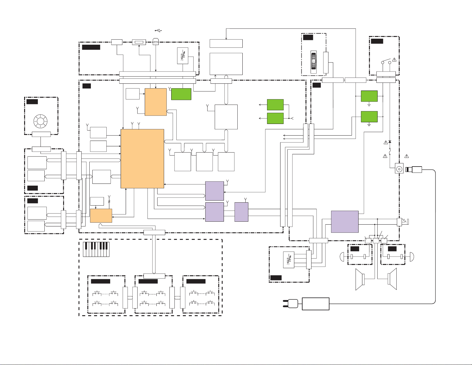
DGX-620/YPG-625
BLOCK DIAGRAM
■
(A-1~C2)
CN1(17P)
CN1(17P)
(C#2~C5)
CN3(17P)
CN1(17P)
(C#5~C7)
PA-5D
(AC Adaptor)
28CA1-2001000277
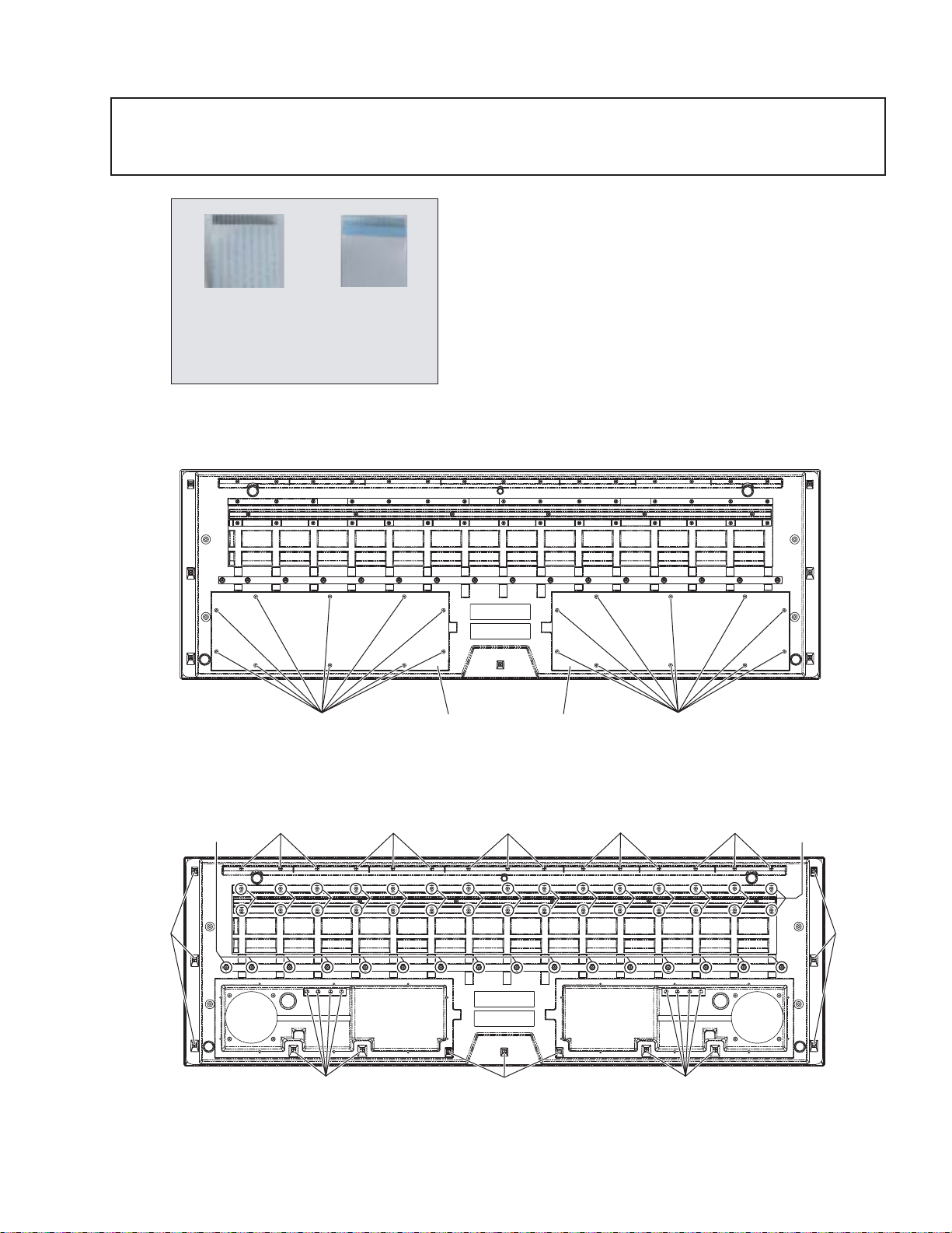
■ DISASSEMBLY PROCEDURE
Caution: 1) Flat cable’s contacts are visible from the back.
Pay attention not to insert and install the cable to the connector inversely. (Fig.1)
2) Be sure to attach the removed filament tape just as it was before removal.
Front Side (Printed Side) Back side
(Fig.1)
<Bottom View>
DGX-620/YPG-625
1. Lower Case Assembly (Time required: About 9 minutes)
1-1 Remove the twenty (20) screws marked [510A].
The bottom boards L and R can then be removed.
(Fig.2)
1-2 Remove the thirty six (36) screws marked [500] and
the forty six (46) screws marked [510B].
The lower case assembly can then be removed. (Fig.3)
[500]
<Bottom View>
[510A] [510A]
Bottom Board (L) Bottom Board (R)
(Fig.2)
[510]: Bind Head Tapping Screw-B 4.0X16 MFZN2W3 (WF154100)
[500] [500] [500]
[500]
(Fig.3)
[500]: Bind Head Tapping Screw-B 4.0X12 MFZN2W3 (WE981200)
[510]: Bind Head Tapping Screw-B 4.0X16 MFZN2W3 (WF154100)
[500] [500]
[500][500]
[510B][510B]
[500]
9
DGX-620/YPG-625
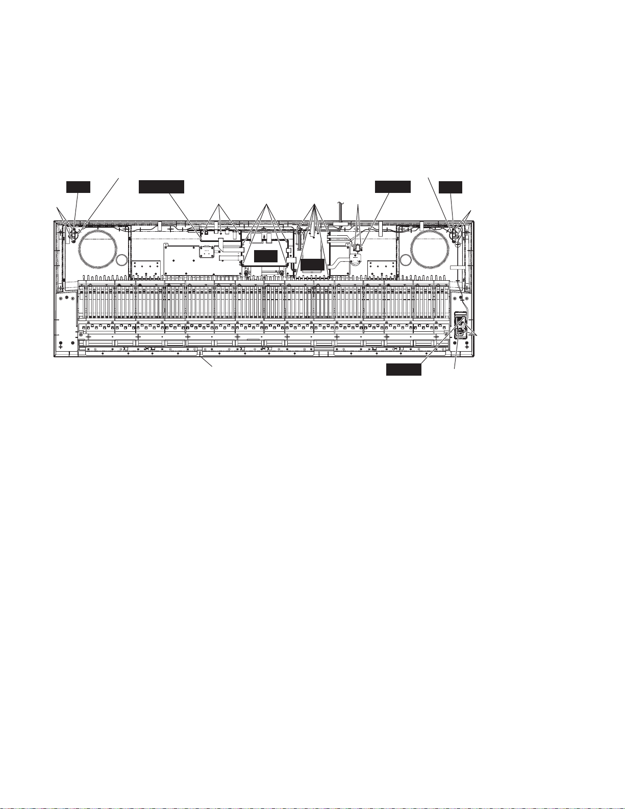
2. DM Circuit Board (Time required: About 10 minutes)
2-1 Remove the lower case assembly. (See procedure 1.)
2-2 Remove the four (4) screws marked [480A].
The DM circuit board can then be removed. (Fig.4)
Speaker
(Tweeter(R))
[480B]
TW
(R)
DJACK
[480G]
[480A] [480D] [480E]
DM
Upper Case
[480]: Bind Head Tapping Screw-B 3.0X8 MFZN2W3 (WE774300)
3. TW Circuit Board, Speaker (Tweeter) (Time required: About 9 minutes)
3-1 Remove the lower case assembly. (See procedure 1.)
3-2 Remove the two (2) screws marked [480B]. The TW
circuit board and speaker (tweeter) can then be removed.
(Fig.4)
* The left and right speakers (tweeters) can be removed in
the same way.
4. PB Circuit Board, Wheel Assembly (Time required: About 9 minutes)
4-1 Remove the lower case assembly. (See procedure 1.)
4-2 Remove the two (2) screws marked [480C]. The PB
circuit board and the wheel assembly can then be
removed. (Fig.4)
* Make sure to mount the wheel assembly on the volume
shaft of the PB circuit board by firmly inserting it into the
shaft.
Speaker
(Tweeter(L))
PSW
TW
(L)
[480B]
AM
[480C]
PB
(Fig.4)
5. AM Circuit Board (Time required: About 10 minutes)
5-1 Remove the lower case assembly. (See procedure 1.)
5-2 Remove the seven (7) screws marked [480D]. The AM
circuit board can then be removed. (Fig.4)
6. PSW Circuit Board (Time required: About 9 minutes)
6-1 Remove the lower case assembly. (See procedure 1.)
6-2 Remove the two (2) screws marked [480E].
The PSW circuit board can then be removed. (Fig.4)
7. DJACK Circuit Board (Time required: About 10 minutes)
7-1 Remove the lower case assembly. (See procedure 1.)
7-2 Remove the three (3) screws marked [480G].
The DJACK circuit board can then be removed. (Fig.4)
Wheel Assembly
10
DGX-620/YPG-625
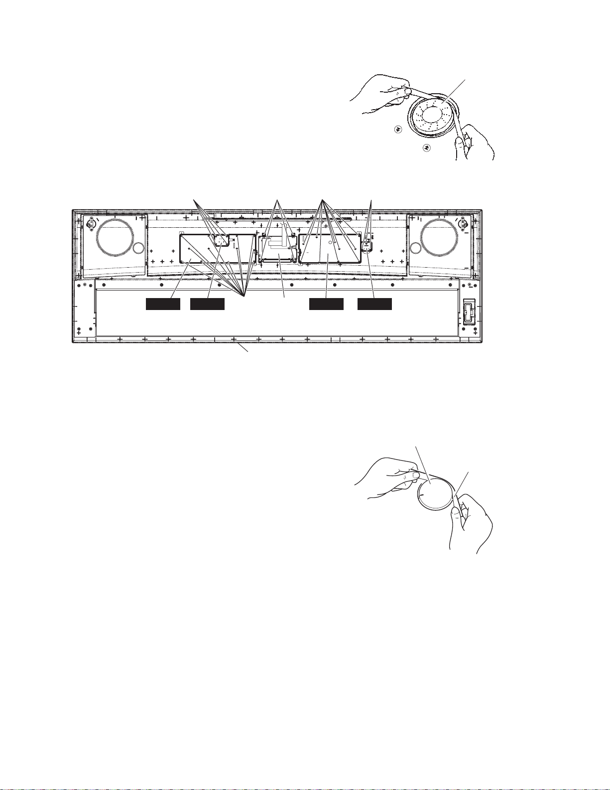
8. ENC Circuit Board (Time required: About 10 minutes)
8-1 Remove the lower case assembly. (See procedure 1.)
8-2 Remove the encoder knob from the control panel. (Fig.5)
8-3 Remove the four (4) screws marked [480H]. The ENC
circuit board can then be removed. (Fig.6)
[480H]
PNR ENC MVR
[480I]
Upper Case
[480J] [480F]
LCD Unit
Encoder knob
(Fig.5)
[480K]
PNL
(Fig.6)
[480]: Bind Head Tapping Screw-B 3.0X8 MFZN2W3 (WE774300)
9. PNR Circuit Board (Time required: About 11 minutes)
9-1 Remove the lower case assembly. (See procedure 1.)
9-2 Remove the twelve (12) screws marked [480I]. The PNR
circuit board can then be removed. (Fig.6)
10. MVR Circuit Board (Time required: About 10 minutes)
10-1 Remove the lower case assembly. (See procedure 1.)
10-2 Remove the volume knob from the control panel. (Fig.7)
10-3 Remove the three (3) screws marked [480K]. The MVR
circuit board can then be removed. (Fig.6)
11. PNL Circuit Board (Time required: About 12 minutes)
11-1 Remove the lower case assembly. (See procedure 1.)
11-2 Remove the AM circuit board. (See procedure 5.)
11-3 Remove the ten (10) screws marked [480F]. The PNL
circuit board can then be removed. (Fig.6)
Volume Knob
Cloth
(Fig.7)
11
DGX-620/YPG-625
12. LCD Unit (Time required: About 11 minutes)
12-1 Remove the lower case assembly. (See procedure 1.)
12-2 Remove the DM circuit board. (See procedure 2.)
12-2 Remove the four (4) screws marked [480J].
The LCD unit can then be removed. (Fig.6)
[40]
Speaker
(Woofer(L))
Lower Case
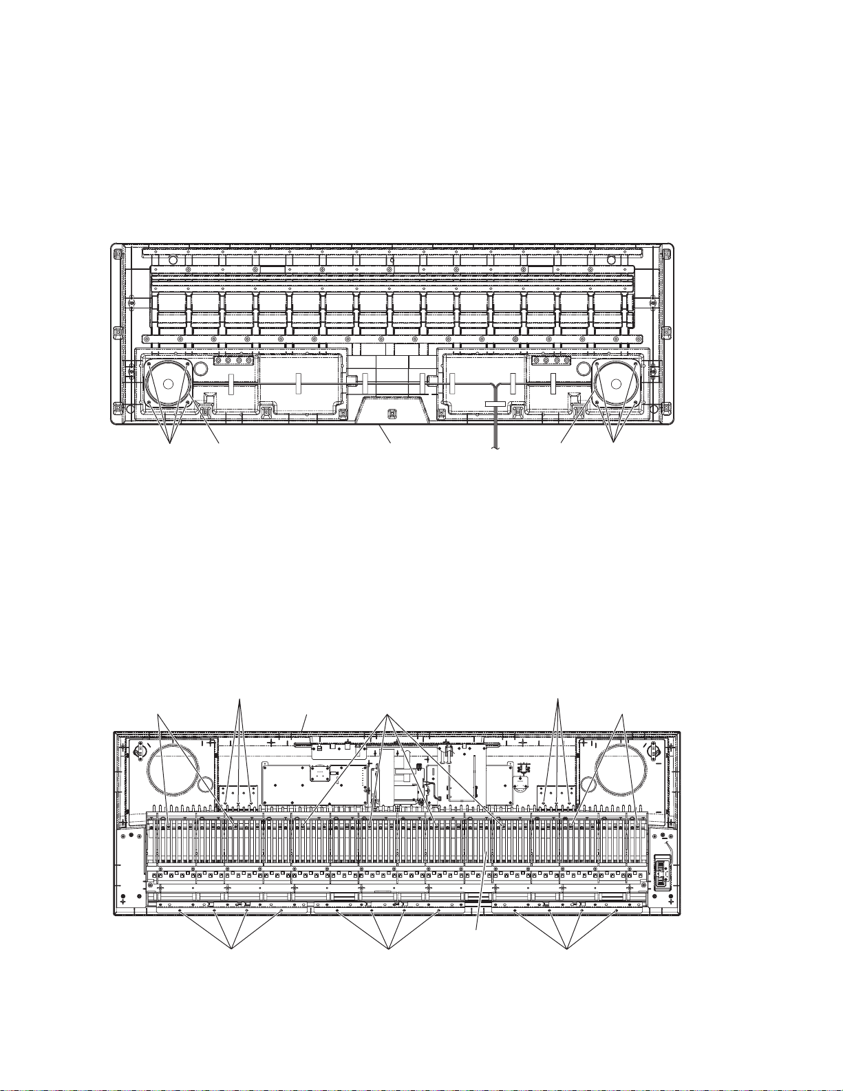
13. Speaker (Woofer) (Time required: About 10 minutes)
13-1 Remove the lower case assembly. (See procedure 1.)
13-2 Remove the four (4) screws marked [40]. The speaker
(woofer) can then be removed. (Fig.8)
* The left and right speakers (woofers) can be removed
in the same way.
Speaker
(Woofer(R))
[40]
(Fig.8)
[40]: Bind Head Tapping Screw-B 4.0X12 MFZN2W3 (WE981200)
14. Keyboard Assembly
(Time required: About 13 minutes)
14-1 Remove the lower case assembly. (See procedure 1.)
14-2 Remove the six (6) screws marked [480L], the twelve (12)
screws marked [480M] and the eight (8) screws marked
[560].
[480L]
Upper Case
[560][560]
The keyboard assembly can then be removed from the
upper case assembly. (Fig.9)
[480L]
[560]
12
Keyboard Assembly
[480M] [480M] [480M]
(Fig.9)
[480]: Bind Head Tapping Screw-B 3.0X8 MFZN2W3 (WE774300)
[560]: Bind Head Tapping Screw-B 3.0X20 MFZN2W3 (WF489300)
DGX-620/YPG-625
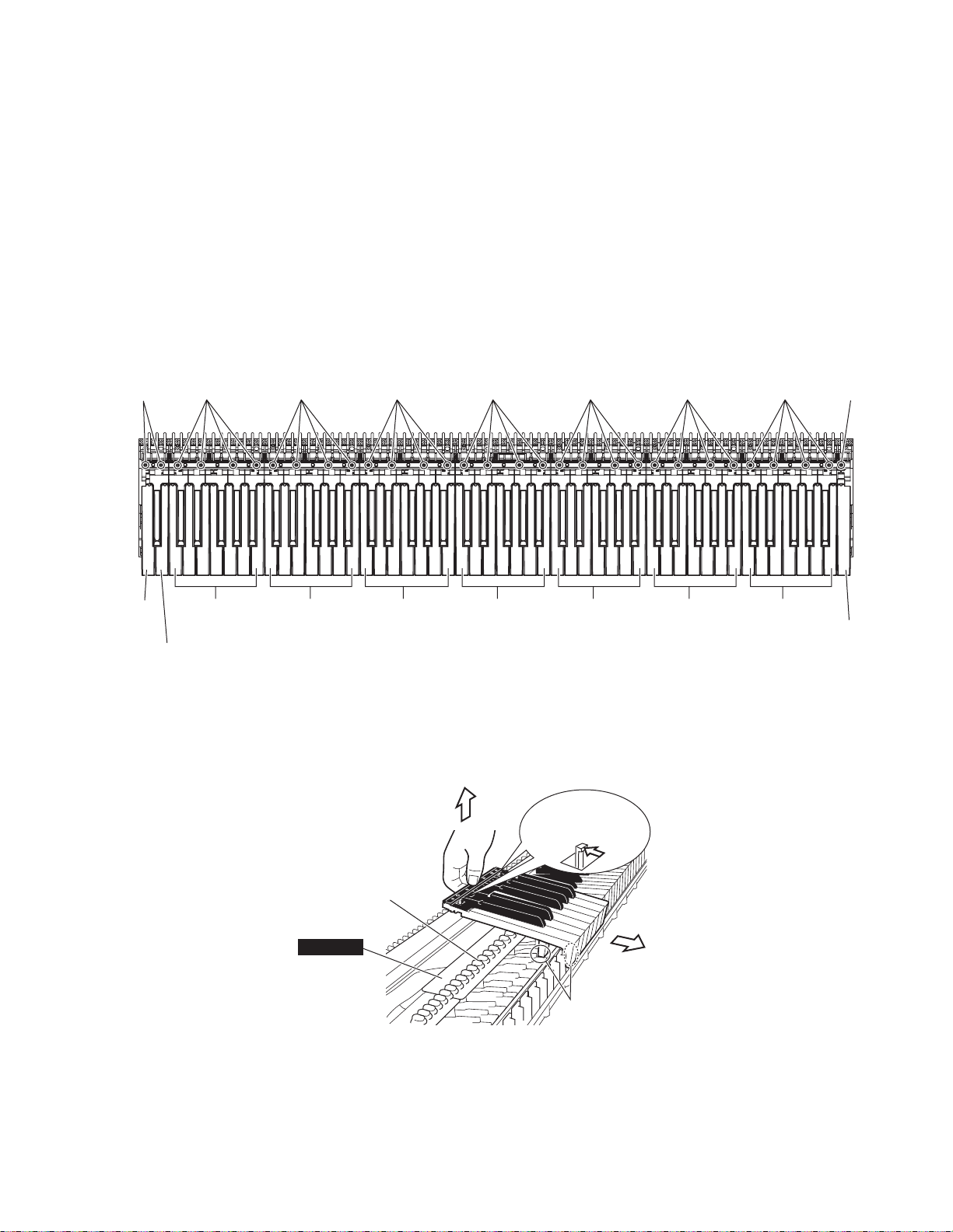
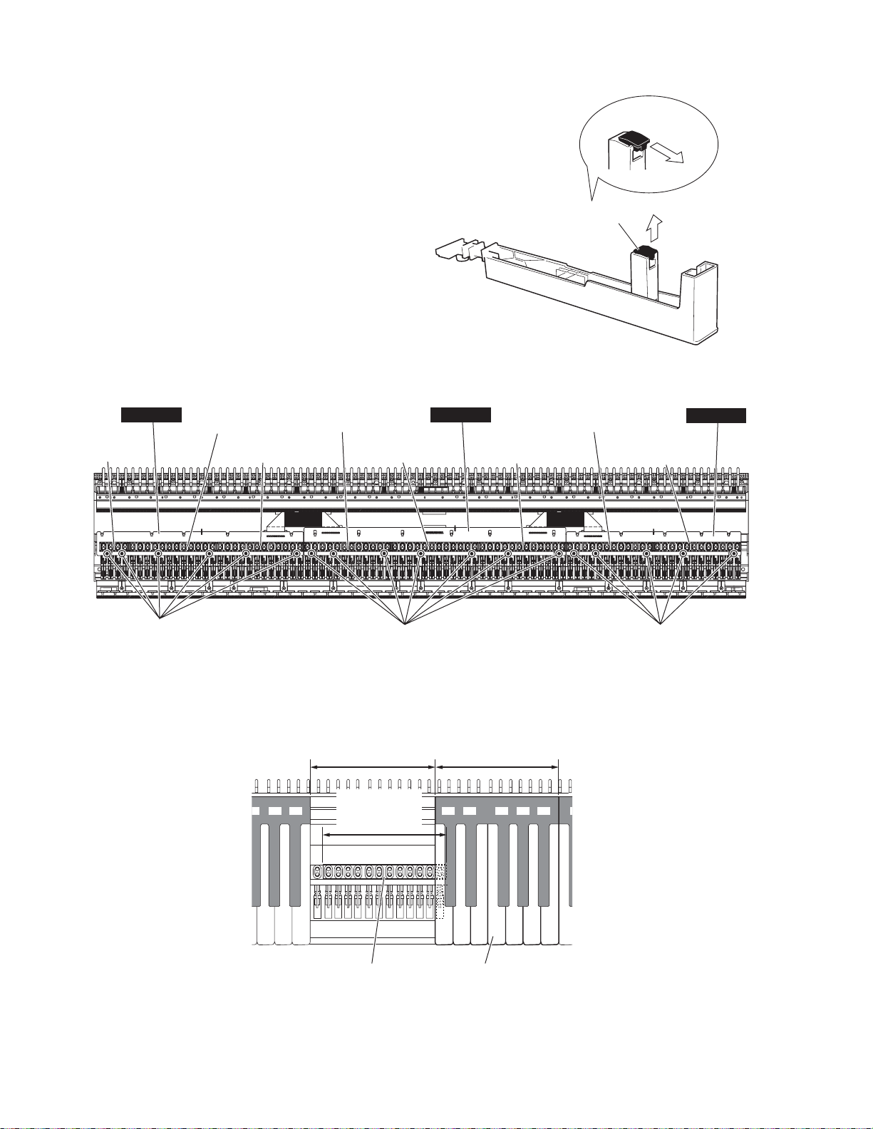
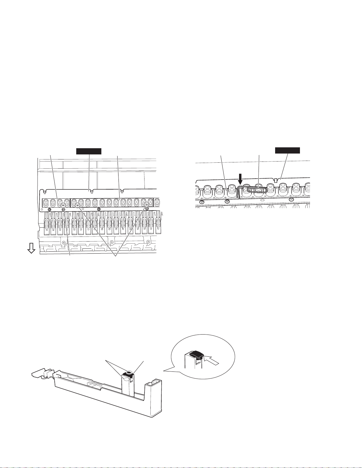
15. Disassembling the Keyboard Assembly
15-1 White key assembly and black key assembly
Remove the four (4) screws marked [270A] fixing the
black and white key assembly for one octave (C-B).
To remove the back of the black and white key assembly
of each octave, while pushing the end lug of white keys
rearward and lifting the back of keys, slide the black and
white key assembly towards you. (Fig.10, Fig.11)
<Top view>
[270B]
[270A] [270A] [270A] [270A] [270A] [270A] [270A] [270C]
15-2 When removing white keys numbered as A-1 and B-1
key and black key, remove two (2) screws marked
[270B] and then lift the back of the keys and slide the
black and white keys towards you. (Fig.10)
15-3 When removing the C7 key, remove a screw marked
[270C] and then lift the back of C7 key and slide it
towards you. (Fig.10)
Note: When removing white key assembly and black key
assembly, be careful not to allow grease to attach to the
circuit board and rubber contacts, etc. (Fig.11)
A-1 Key
One octave
B-1 Key
(C0-B0)
One octave
(C1-B1)
One octave
(C2-B2)
One octave
(C3-B3)
One octave
(C4-B4)
(Fig.10)
[270]: Bind Head Tapping Screw-P 3.0X16 MFZN2W3 (WE973000)
End lug of white key
Rubber contact
GHL88M
Grease
(Fig.11)
One octave
(C5-B5)
One octave
(C6-B6)
C7 Key
13
DGX-620/YPG-625
15-4 Actuate Rubber
Remove the actuate rubber. (Fig.12)
15-5 Rubber Contact
Remove the black and white key assembly for two octaves
related to the subject rubber contact. The rubber contact
can then be removed. (Fig.13, Fig.14)
* Note that the rubber contact has a specific installation
direction.
* One rubber contact fits for C#-C (for C-B keys).
<Top View>
Remove in this way.
Actuate rubber
(Fig.12)
Rubber contact
[260A]
Rubber contact
Rubber contact
[260]: Bind Head Tapping Screw-P 2.6X8 MFZN2W3 (WF267300)
Rubber contact Rubber contact
Rubber contact
[260B] [260C]
GHL88MGHL88L
Rubber contact Rubber contact
(Fig.13)
One octave
(C-B)
One octave
(C#-C)
One octave
(C-B)
GHL88H
14
Rubber contact Key
To remove the rubber contact for one octave, keys for 2 octaves need to be removed.
(Fig.14)
DGX-620/YPG-625
15-6 GHL88L Circuit Board
Remove the black and white key assembly (A1-B2).
(See procedure 15-1.)
Remove the six (6) screws marked [260A]. The GHL88L
circuit board can then be removed. (Fig.13)
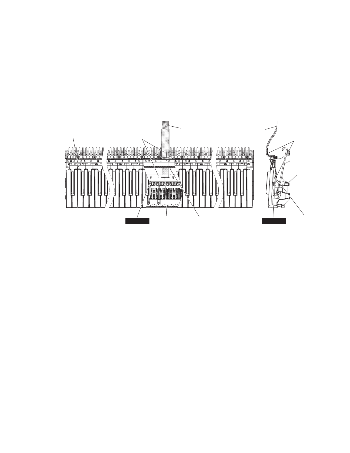
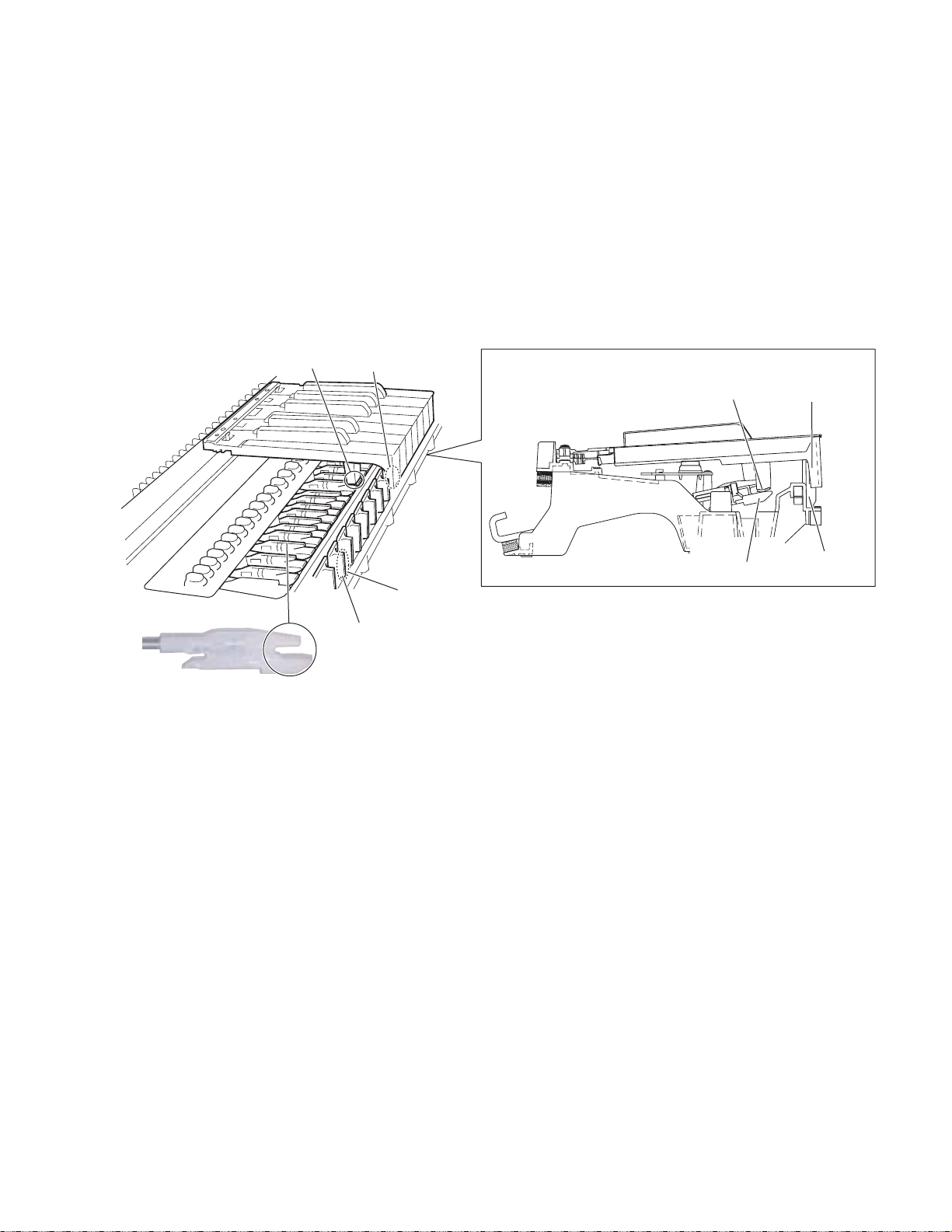
15-7 GHL88M Circuit Board
Remove the black and white key assembly (C1-B5).
(See procedure 15-1.)
Remove the seven (7) screws marked [260B]. The
GHL88M circuit board can then be removed. (Fig.13)
Detach the filament tape and disconnect the FFC cable.
(Fig.15)
<Top view> <Side view>
Keyboard assembly
FFC cable
Filament tape
FFC cable
Filament tape
Frame
GHL88M
CN2 (27P)
(Fig.15)
Through hole
GHL88M
CN2
(27P)
15
DGX-620/YPG-625
15-8 GHL88H Circuit Board
Remove the black and white key assembly (C5-C7).
(See procedure 15-1.)
Remove the five (5) screws marked [260C]. The GHL88H
circuit board can then be removed. (Fig.13)
<Rear view>
Hammer axis
Bottom side
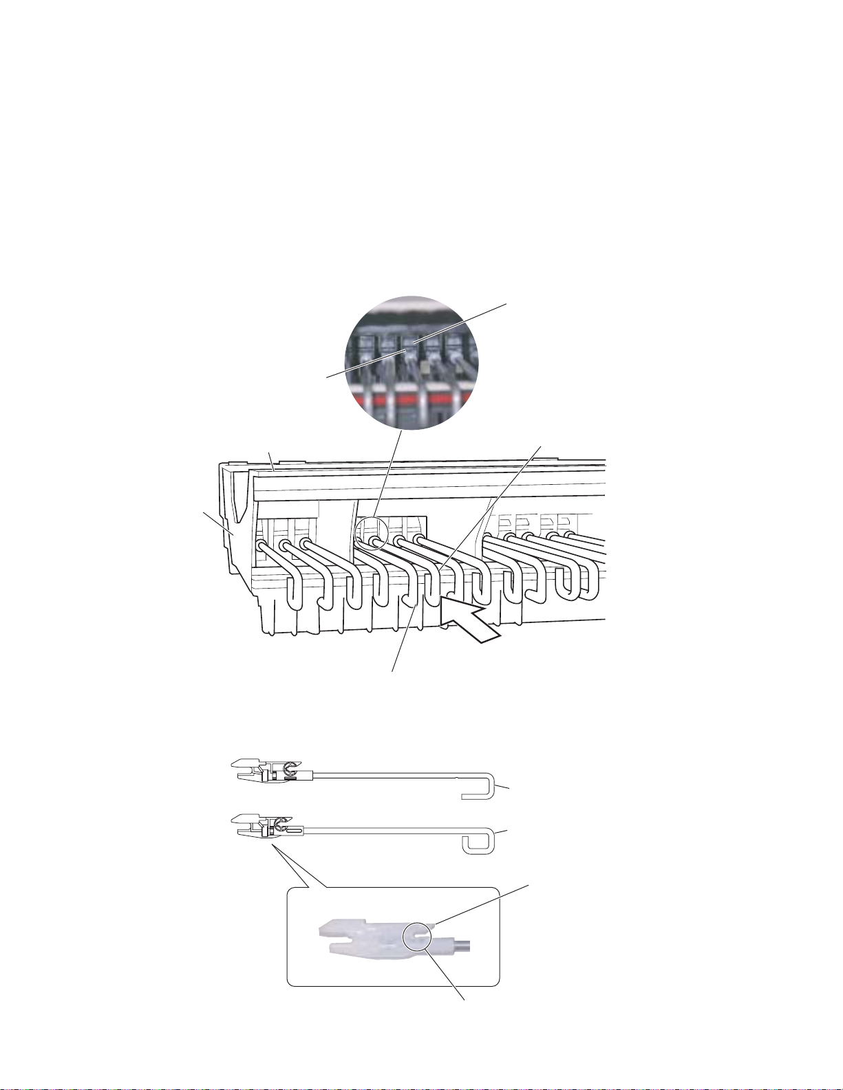
15-9 Hammer (White Key), (Black Key)
Remove the black and white key assembly for the
related keys.
With the key frame placed upside down, push the
hammer forward from the rear, then a click sound is
heard and the hammer bearing section can be removed
from the hammer axis of the key frame.
Take out the hammer sideways. (Fig.16, Fig.17)
* When removing the hammer, take care not to cause
damage to the hammer bearing and its claw.
Bearing claw
Hammer, white key
Frame
Push
Hammer, black key
(Fig.16)
Hammer, B1 (black key)
Hammer, W1 (white key)
Bearing claw
16
Bearing section
(Fig.17)
DGX-620/YPG-625
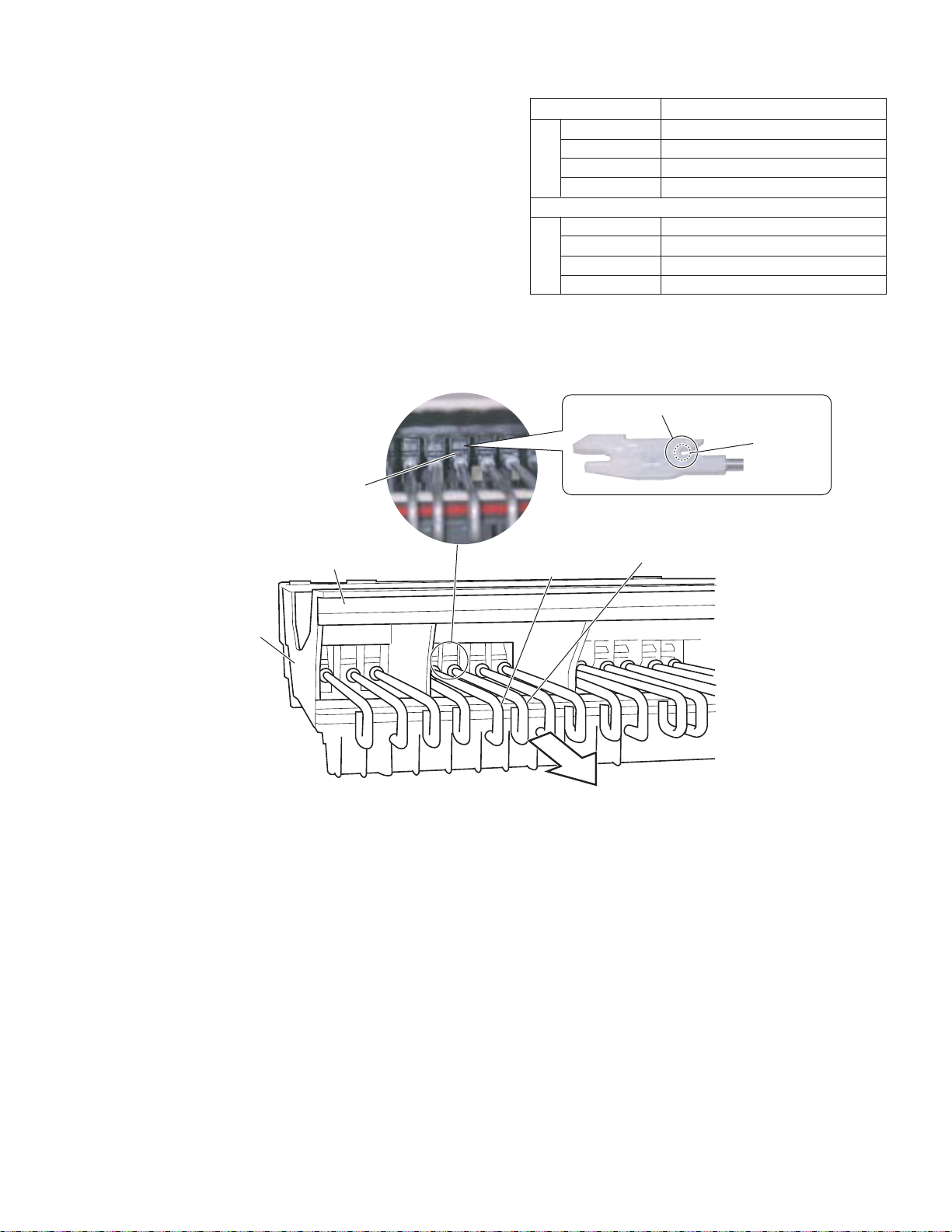
16. Assembling the Keyboard Assembly
16-1 Hammer (White Key), (Black Key)
After applying grease to the bearing section of the
hammer, bring the hammer (white key)(black key)
sideways from the rear, fit its bearing section to the
hammer axis of the key frame and pull it forward until a
click sound is heard. (Fig.18)
* There are 8 hammer types differing in weight. Be sure to
check the type of the hammer for correct installation.
(Table 1)
<Rear view>
Hammer axis
Bottom side
Part Name Range for Applicable Tone Keys
Hammer, W1
Hammer, W2
Hammer, W3
White KeyBlack Key
Hammer, W4
Hammer, B1
Hammer, B2
Hammer, B3
Hammer, B4 D#5 - A#6
Bearing section
Hammer, black key
A-1 - F1
G1 - E3
F3 - D5
E5 - C7
A#-1 - F#1
G#1 - D#3
F#3 - C#5
(Table 1)
Apply grease
Hammer, white key
Frame
Pull forward
(Fig.18)
17
DGX-620/YPG-625
16-2 GHL88L Circuit Board
Tighten the six (6) screws marked [260A] to fix the
GHL88L circuit boards. (Fig.13)
16-3 GHL88M Circuit Board
Connect the FFC cable to CN2 of the GHL88M circuit
board, attach the filament tape. (Fig.15)
Pass the end of the cable into the through hole in the
frame and pull it out from its outlet. (Fig.15)
Tighten the seven (7) screws marked [260B] to fix the
GHL88M circuit board. (Fig.13))
Rubber contact
GHL88L
Rubber contact
16-4 GHL88H Circuit Board
Tighten the five (5) screws marked [260C] to fix the
GHL88H circuit board. (Fig.13)
16-5 Rubber Contact
Note that the rubber contact has s specific installation
direction. Be careful not to install it in the wrong
direction.
* A triangle mark (
∆
) on the rubber contact must face
the front. (Fig.19)
To prevent looseness of the rubber contact, fit it
securely in place using a clip or similar object.
(Fig.20)
Rubber contact Clip
GHL88L
Front
Triangle mark Triangle mark
(Fig.19)
16-6 Actuate Rubber
After applying grease to top and bottom faces of the
actuate rubber, fit it to the white key (black key). (Fig.21)
Apply grease
(Fig.20)
Fit in this way.
Actuate rubber
18
(Fig.21)
DGX-620/YPG-625
16-7 White key assembly and black key assembly
After applying grease to the key guide, install the white
key assembly/black key assembly.
At this time, check to make sure that the key guide of the
key frame and inside slit at the front of white key as well
as the contact arm of the hammer and actuate rubber of
the white key assembly/black key assembly are installed
properly. (Fig.22)
Use the four (4) screws marked [270A] to fix 1 octave
white key assembly/black key assembly. (Fig.10)
Actuate rubber
Slit
16-8 Use the two (2) screws marked [270B] to fix the A-1 to
B-1 keys. (Fig.10)
16-9 Use a screw marked [270C] to fix the C7 key. (Fig.10)
<Side view>
Actuate rubber
Slit
Hammer
Contact arm
Key guide
Apply grease
(Fig.22)
Contact arm
Key guide
19
 Loading...