

Page 1

50/144/430 MHz
TRIPLE-BAND HEAVY DUTY
SUBMERSIBLE TRANSCEIVER
OPERATING MANUAL
VERTEX STANDARD CO., LTD.
4-8-8 Nakameguro, Meguro-Ku, Tokyo 153-8644, Japan
VERTEX STANDARD
US Headquarters
17210 Edwards Rd., Cerritos, CA 90703, U.S.A.
International Division
8350 N.W. 52nd Terrace, Suite 201, Miami, FL 33166, U.S.A.
YAESU EUROPE B.V.
P.O. Box 75525, 1118 ZN Schiphol, The Netherlands
YAESU UK LTD.
Unit 12, Sun Valley Business Park, Winnall Close
Winchester, Hampshire, SO23 0LB, U.K.
VERTEX STANDARD HK LTD.
Unit 5, 20/F., Seaview Centre, 139-141 Hoi Bun Road,
Kwun Tong, Kowloon, Hong Kong
Page 2

Contents
Introduction ..................................................................... 1
Controls & Connections ................................................. 2
Display Icons & Indicators ............................................ 3
Keypad Function ............................................................ 4
Accessories & Options ................................................... 6
Installation of Accessories ............................................. 7
Antenna Installation ..................................................... 7
How to Install the Quick Draw Belt Clip ................... 8
Installation of FNB-80LI Battery Pack....................... 8
Installation of FBA-23 (option)
Alkaline Battery Case............................................. 9
Battery Life Information ............................................ 10
AC Operation Using NC-72 ..................................... 10
Interface of Packet TNCs ............................................ 11
Operation ....................................................................... 12
Switching Power On and Off .................................... 12
Adjusting the Volume Level ..................................... 12
Squelch Adjustment ................................................... 13
Selecting the Operating Band.................................... 14
Selecting the Frequency Band ................................... 15
Frequency Navigation................................................ 16
Audio Muting............................................................. 17
BAND Link................................................................ 17
Transmission .............................................................. 17
Changing the Transmitter Power Level ............... 18
VOX Operation ......................................................... 19
AM Broadcast Reception .......................................... 20
AM Aircraft Reception.............................................. 20
FM Broadcast/TV Audio Reception ......................... 21
Weather Broadcast Reception .................................. 22
Keyboard Locking ..................................................... 23
Keypad/LCD Illumination ......................................... 24
Disabling the Keypad Beeper ................................... 24
Advanced Operation .................................................... 25
Setting the Frequency Display Image Size ............... 25
Changing the Channel Steps ..................................... 25
Changing the Operating Mode .................................. 26
Repeater Operation.................................................... 27
CTCSS Operation ...................................................... 30
DCS Operation .......................................................... 31
Tone Search Scanning ............................................... 32
CTCSS/DCS Bell Operation ..................................... 33
Split Tone Operation ................................................. 33
Tone Calling (1750 Hz) ............................................ 34
ARTS (Automatic Range Transponder System) ...... 35
DTMF Operation ....................................................... 38
Emergency Channel Operation ................................. 39
ATT (Front End Attenuator) ..................................... 40
Receive Battery Saver Setup ..................................... 40
TX Battery Saver ....................................................... 41
Disabling the “STROBE” ......................................... 41
Automatic Power-Off (APO) Feature ....................... 42
Transmitter Time-Out Timer (TOT) ......................... 42
Busy Channel Lock-Out (BCLO) ............................. 43
MIC Monitor ............................................................. 43
Changing the TX Deviation Level ............................ 44
Memory Mode .............................................................. 45
Regular Memory Operation ...................................... 46
Memory Storage ................................................... 46
Storing Independent Transmit Frequencies
(“Odd Split”) ........................................................ 46
Memory Recall ..................................................... 47
HOME Channel Memory ..................................... 47
Labeling Memories ............................................... 48
Memory Offset Tuning......................................... 49
Masking Memories ............................................... 50
Memory Group Operation ................................... 51
Moving Memory Data to the VFO ...................... 52
Memory Only Mode ............................................. 52
Hyper Memory Operation ......................................... 53
One-Touch Memory Operation ................................ 54
Sort-wave Broadcast Station Memory Channels ..... 55
VHF Marine Memory Channels ............................... 56
Scanning ......................................................................... 57
VFO Scanning ........................................................... 58
Memory Scanning...................................................... 58
Temporary Memory Skip ..................................... 59
How to Skip (Omit) a Channel
During Memory Scan Operation.......................... 59
Preferential Memory Scan.................................... 60
Programmable (Band Limit) Memory Scan (PMS) . 61
“Priority Channel” Scanning (Dual Watch) ............. 61
Automatic Lamp Illumination on Scan Stop ............ 62
Band Edge Beeper ..................................................... 62
Spectrum Analyzer Operation................................... 63
Smart Search Operation ............................................ 64
Channel Counter Operation ...................................... 66
Internet Connection Feature ...................................... 67
Sensor Mode .................................................................. 68
Sensor Mode Option ................................................. 69
Clock Set .............................................................. 69
Selecting the Wave Form Display ....................... 70
Selecting the Unit of Temperature Display ......... 70
Selecting the Unit of
Atmospheric Pressure Meter (Barometer) ........... 70
Correcting the Atmospheric Pressure Meter
(Barometer Offset) ............................................... 70
Selecting the Unit of Altimeter ............................ 71
Correcting the Altimeter Setting
(Altimeter Offset) ................................................. 71
Timer Operation ........................................................... 72
Display Customization ................................................. 73
Icon Mode .................................................................. 73
Icon Selection ............................................................ 73
Icon Editor ................................................................. 74
Power-Off Display Mode .......................................... 75
S-and TX Power Meter Symbols.............................. 76
Font Editor ................................................................. 77
Display Contrast ........................................................ 78
Display Dimmer......................................................... 78
STROBE Customization ........................................... 79
Reset Procedures .......................................................... 80
Cloning ........................................................................... 81
Set Mode ........................................................................ 82
Installation of the SU-1 ................................................ 97
Specifications................................................................. 98
Appendix ...................................................................... 100
Page 3
INTRODUCTION
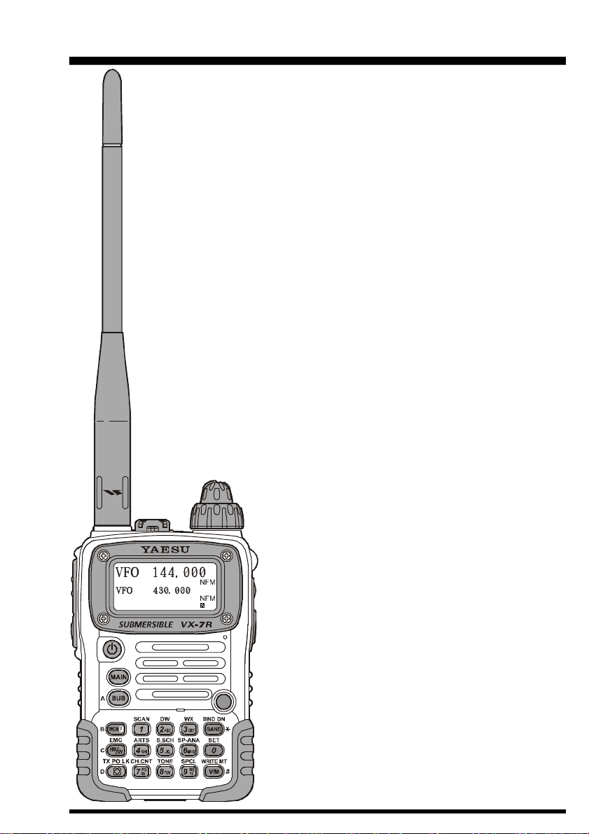
The VX-7R is a miniature 3-band FM transceiver
with extensive receive frequency coverage, providing leading-edge features for VHF and UHF twoway amateur communications, along with unmatched
monitoring capability.
The VX-7R’s small size allows you to take it anywhere – hiking, skiing, or while walking around town
– and its operating flexibility brings the user many
avenues of operating enjoyment. Besides 50, 144,
and 430 MHz transceive operation, the VX-7R provides 222 MHz QRP (0.3 Watts) transceive operation, receive coverage of the AM (MF) and FM
broadcast bands, HF Shortwave Bands up to 16 MHz,
VHF and UHF TV bands, the VHF AM aircraft band,
and a wide range of commercial and public safety
frequencies! Dual In-band Receive (V/V and U/U)
lets you keep track of two active frequencies. And
the optional Barometer pressure Sensor Unit provides
readout of barometric pressure and altitude while
mountain climbing or hiking, and it also generates a
Weather Forecast based on measured data.
The transmitter section provides 5 Watts of clean
power output on the FM operation on the 50 MHz,
144 MHz, and 430 MHz bands with the supplied
FNB-80LI Battery Pack, and 0.3 Watts output on
222 MHz, and 1 Watt of carrier output for AM operation on 50 MHz. Both CTCSS and DCS tone signaling formats are built into the VX-7R, in addition
to Yaesu’s exclusive ARTSTM-(Auto-Range Transponder System), which “beeps” the user when you
move out of communications range with another
ARTSTM-equipped station.
We appreciate your purchase of the VX-7R, and encourage you to read this manual thoroughly, so as to
learn about the many exciting features of your exciting new Yaesu hand-held transceiver!
VX-7R OPERATING MANUAL 1
Page 4
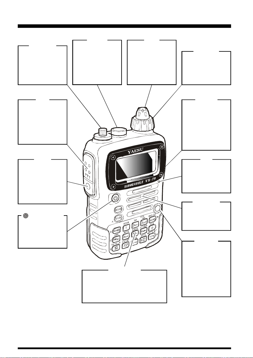
CONTROLS & CONNECTIONS
ANTENNA
Connect the supplied rubber flex antenna (or another
antenna presenting
a 50-Ohm impedance) here.
PTT
(“Push To Talk”)
Press this switch
inward to transmit,
and release it (to
receive) after your
transmission is
completed.
MONI
Pressing this key
disables the noise
squelching action,
allowing you to
hear very weak signals near the background noise level.
(
PWR) Switch
Press and hold this
switch for 2 seconds to toggle the
transceiver’s power
on and off.
MIC/SP
This four-conductor
miniature jack provides connection
points for microphone audio, earphone audio, PTT,
and ground.
KEYBOARD
These 17 keys select many of the
most important operating features
on the VX-7R.
This function of the keys are described in details on pages 4 and 5.
The main tuning
Dial is used for setting the operating
frequency, and also
is used for Menu
selections and
other adjustments.
DIAL
VOLUME
This control adjusts
the audio volume
level. Clockwise rotation increases the
volume level.
EXT DC
This coaxial DC
jack allows connection to an external
DC power source
(10-16V DC). The
center pin of this
jack is the Positive
(+) line.
MIC
The internal microphone is located at
the bottom righthand corner of the
display.
SPEAKER
The internal
speaker is located
directly below the
display.
STROBE
The STROBE is
the unique indicator which indicates
the transceiver’s
status.
You may customize
the STROBE color
setup via the Menu
mode.
VX-7R OPERATING MANUAL2
Page 5
“Main” Band
Frequency Control
“Main” Band S- & PO Meter
“Sub” Band
Frequency Control
“Sub” Band S- & PO Meter
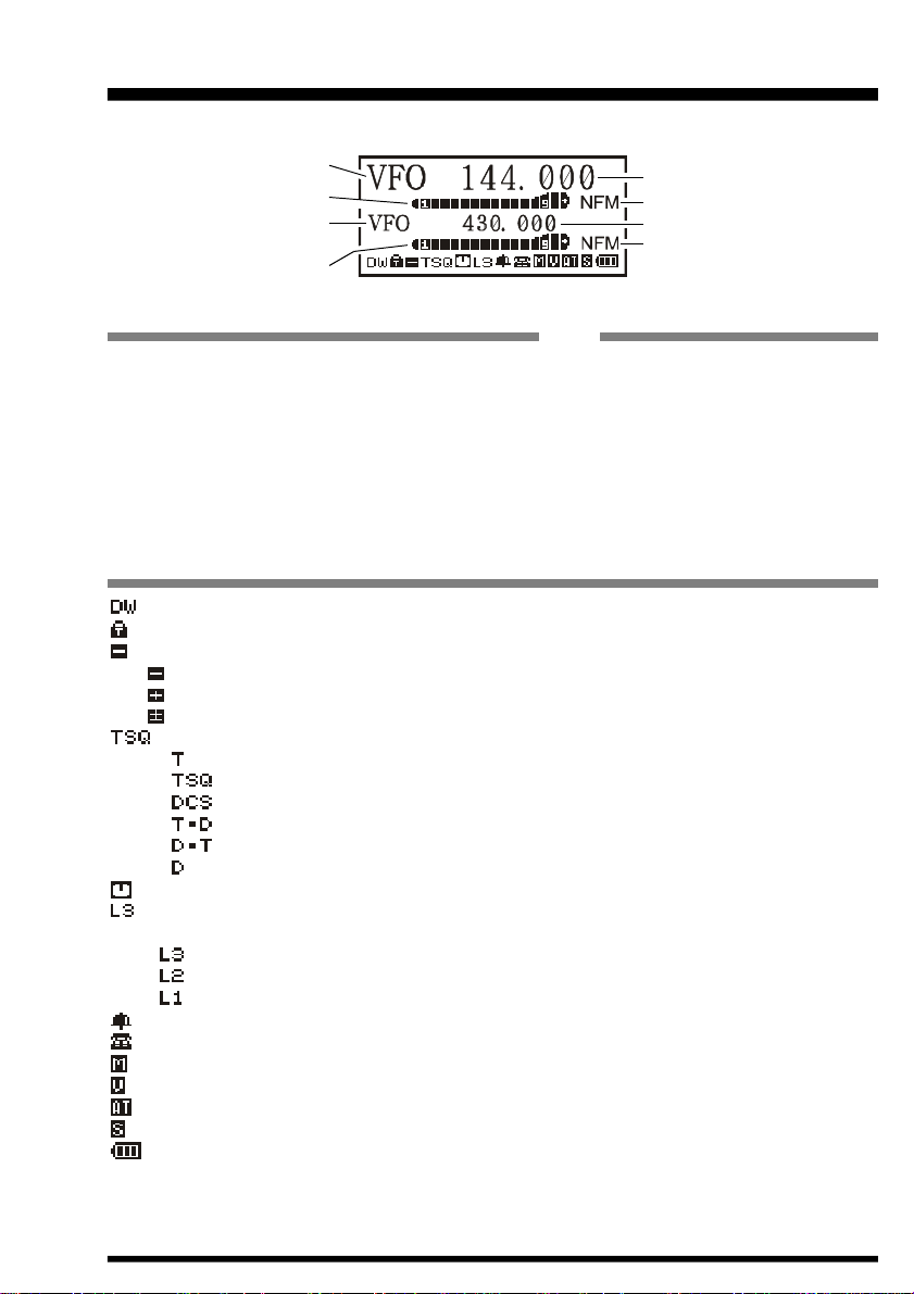
DISPLAY ICONS & I NDICATORS
“Main” Band Frequency
“Main” Band Operating Mode
“Sub” Band Frequency
“Sub” Band Operating Mode
FREQUENCY CONTROL
VFO: VFO Mode (page 15)
MR: Memory Mode (page 45)
MT: Memory Tume Mode (page 49)
PMS: Programable Memory Scan Mode (page 61)
WX: Weather Channel (page 22)
Sea: Marine Channel (page 56)
HYP: Hyper Memoy Mode (page 53)
OTM: One Touch Memory Mode (page 54)
LST: Short-wave Broadcast StationMemory (page 55)
ICON
: Dual Watch Active (page 61)
: Key Lock Active (page 23)
: Repeater Shift Direction (page 27)
: Minus (–) Shift
: Plus (+) Shifh
: Odd Splits
: CTCSS/DCS Operation (page 30)
: Tone Encoder
: Tone Squelch
: Digital Code Squelch (DCS)
: TX: Tone Encoder, RX: DCS Decoder
: TX: DCS Encoder, RX: Tone Decoder
: DCS Encoder
: Automatic Power-Off Active (page 42)
:Low TX Power Selected (page 18)
No Icon: High Power
:Low Power 3
:Low Power 2
: Low Power 1
: Bell Alarm Active (page 33)
: DTMF Autodialer Active (page 39)
: Audio Mute Active (page 17)
: VOX Active (page 18)
: RF Front-end Attenuator Active (page 40)
: Battery Saver Active (page 40)
: Low Battery! (page 10)
OPERATING MODE
NFM: FM
WFM: Wide FM
AM: AM
VX-7R OPERATING MANUAL 3
Page 6
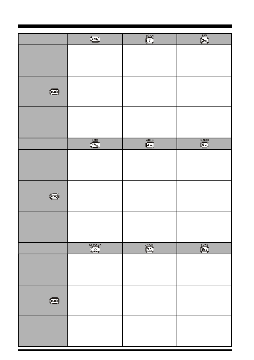
KEYPAD FUNCTIONS
Press Key
Press +
Press and Hold
Key
Press Key
Press +
Press and Hold
Key
Activates the
“Alternate” key Function
No Action
Activates the
“Memory Write” mode
(for memory channel
storage)
Reverses the transmit
and receive frequencies
while working through a
repeater
Switches operation
to the “Home”
(favorite frequency)
Channel
Activates the
EMERGENCY Function
Frequency entry
digit “1”
Activates the Scanner
Store the current setting
into the
Hyper Memory “1”
Frequency entry
digit “4”
Activates the
ARTS Feature
Store the current setting
into the
Hyper Memory “4”
Frequency entry
digit “2”
Activates the
Dual Watch Feature
Store the current setting
into the
Hyper Memory “2”
Frequency entry
digit “5”
Activates the
Smart Search
Feature
Store the current setting
into the
Hyper Memory “5”
TM
Press Key
Press +
Press and Hold
Key
Activates the
Internet Connection
Feature
Select the desired
transmit power output
Activates the
Key Lock Feature
Frequency entry
digit “7”
Activates the
Channel Counter
Feature
Store the current setting
into the
Hyper Memory “7”
VX-7R OPERATING MANUAL4
Frequency entry
digit “8”
Activates the
CTCSS or DCS
Operation
Store the current setting
into the
Hyper Memory “8”
Page 7
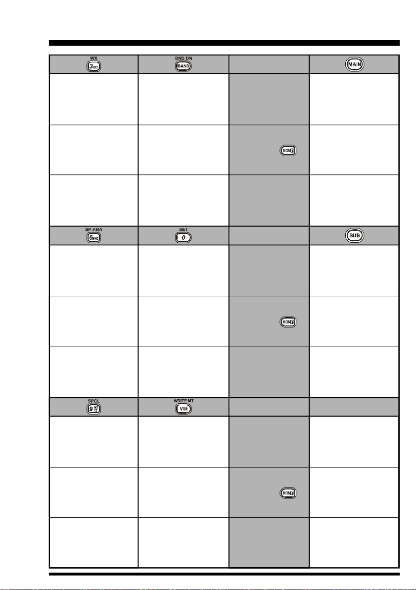
KEYPAD FUNCTIONS
Frequency entry
digit “3”
Recall the
“Weather” broadcast
channel bank
Store the current setting
into the
Hyper Memory “3”
Frequency entry
digit “6”
Activates the
Spectrum Analyzer
(Spectra-ScopeTM)
Feature
Store the current setting
into the
Hyper Memory “6”
Moves operation to the
next-highest
frequency band
Moves operation to the
next-lowest
frequency band
Moves operation to the
next-highest
frequency band
Frequency entry
digit “0”
Enter the “Set”
(Menu) Mode
Store the current setting
into the
Hyper Memory “0”
Press Key
Press +
Press and Hold
Key
Press Key
Press +
Press and Hold
Key
Switches the “Upper”
frequency to be the
“Operating” (TX) Band
Switches the “Upper”
frequency display
between the
“Large Character” and
“Small Character” mode
Activates the
Dual Receive Feature
Switches the “Lower”
frequency to be the
“Operating” (TX) Band
Switches the “Lower”
frequency display
between the
“Large Character” and
“Small Character” mode
Activates the
Dual Receive Feature
MONI Key
USA Version:
Disables the Noise and
Tone Squelch System
EXP Version:
Activates T.CALL (1750 Hz)
for repeater access
USA Version:
Enters the Squelch level
setting mode
EXP Version:
Activates T.CALL (1750 Hz)
for repeater access
No Action
Frequency entry
digit “9”
Enters the
“Special Memory”
mode
Store the current setting
into the
Hyper Memory “9”
Switches
frequency control
between the VFO and
Memory System
No Action
Activates the
“Memory Tune” mode
while in the
Memory Recall mode
Press Key
Press +
Press and Hold
Key
VX-7R OPERATING MANUAL 5
Page 8
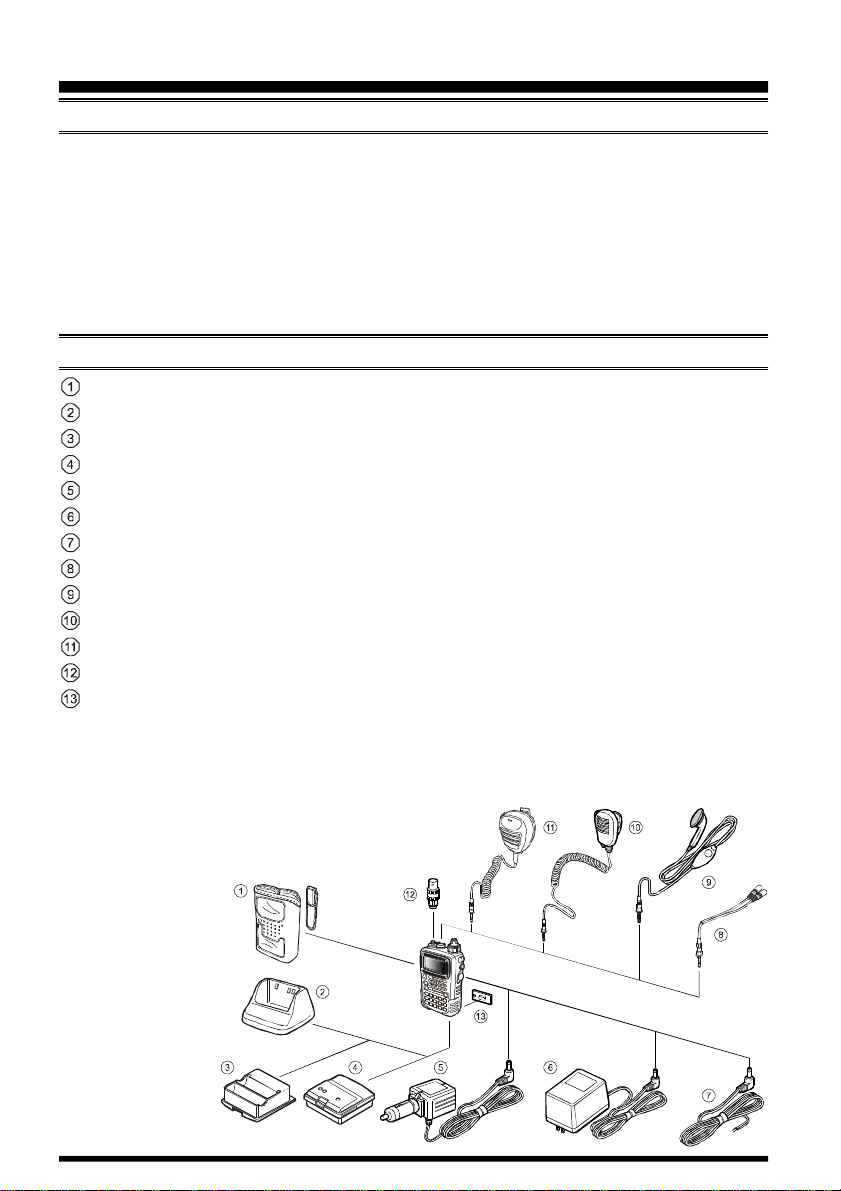
ACCESSORIES & OPTIONS
ACCESSORIES SUPPLIED WITH THE VX-7R
FNB-80LI Battery Pack (7.4V/1,300mAh)
NC-72B/C Battery Charger
Quick Draw Belt Clip
Hand Strap
Antenna
Operating Manual
Warranty Card
AVAILABLE OPTIONS FOR YOUR VX-7R
CSC-88 Soft Case
CD-15A Rapid Charger (requires NC-72B/C)
FBA-23 2 x “AA” Cell Battery Case (batteries not supplied)
FNB-80LI Battery Pack (7.4V/1,300 mAh)
E-DC-5B DC Cable w/Noise Filter
NC-72B/C Battery Charger
E-DC-6 DC Cable; plug and wire only
CT-91 Microphone Adapter
VC-27 Earpiece/Microphone
MH-57A4B Speaker/Microphone
CMP460A Waterproof Speaker/Microphone
CN-3 BNC-to-SMA Adapter
SU-1 Barometric Pressure Sensor Unit
Availability of accessories may vary. Some accessories are supplied as standard per local
requirements, while others may be unavailable in some regions. Consult your Yaesu Dealer
for details regarding these and any newly-available options. Connection of any non-Yaesuapproved accessory, should it cause damage, may
void the Limited Warranty on this apparatus.
VX-7R OPERATING MANUAL6
Page 9
INSTALLATION OF ACCESSORIES
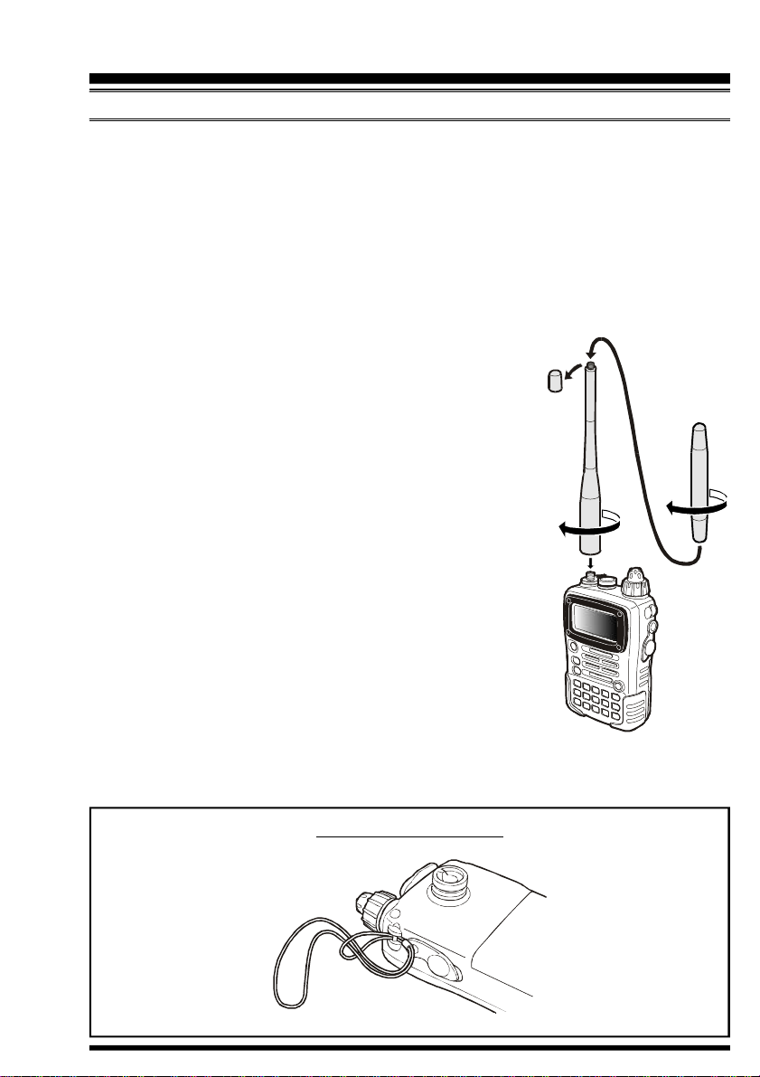
ANTENNA INSTALLATION
The supplied antenna provides good results over the entire frequency range of the transceiver. However, for enhanced base station medium-wave and shortwave reception, you
may wish to connect an external (outside) antenna.
The supplied antenna consists of two sections: the “Base Antenna” (used for operation
above 50 MHz), and the “Extender Element” (used for monitoring of frequencies below 50
MHz).
To install the supplied antenna
Hold the bottom end of the antenna, then screw it onto the mating connector on the transceiver until it is snug. Do not overtighten by use of extreme force.
When operating the VX-7R on the 50 MHz band and lower
frequencies, disconnect the antenna cap from the base antenna,
then screw the Extender Element onto the Antenna Base. Of
course, the VX-7R may be operated on frequencies higher than
the 50 MHz band while the Extender Element is still attached
onto the Antenna Base.
Notes:
¦ Never transmit without having an antenna connected.
¦ When installing the supplied antenna, never hold the upper
part of the antenna while screwing it onto the mating connector on the transceiver.
¦ If using an external antenna for transmission, ensure that
the SWR presented to the transceiver is 1.5:1 or lower.
¦ Take care not lose the antenna cap when removing it from
the Base Antenna.
HAND STRAP INSTALLATION
VX-7R OPERATING MANUAL 7
Page 10
INSTALLATION OF ACCESSORIES
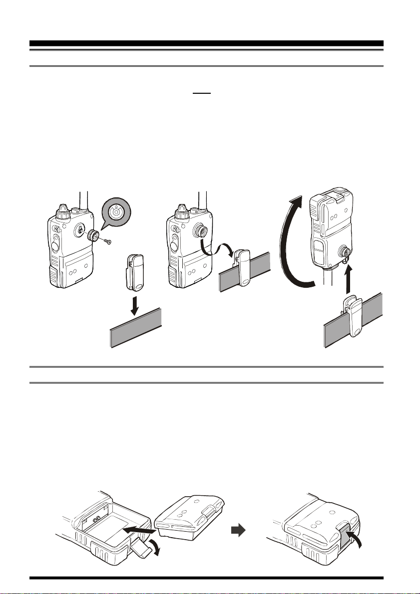
HOW TO INSTALL THE QUICK DRAW BELT CLIP
1. Connect the hanger to the rear of the VX-7R , with the notch pointing directly up, using
the supplied screw (Figure 1). Use only the screw included with the clip to mount
the clip to the back of the VX-7R!
2. Clip the Quick-Draw Belt Clip onto your belt (Figure 2).
3. To install the VX-7R into the Quick-Draw Belt Clip, align the hanger with the QuickDraw Belt Clip, and slide the VX-7R into its slot until a click is heard (Figure 3).
4. To remove the VX-7R from the Quick-Draw Belt Clip, rotate the VX-7R 180 degrees,
then slide the VX-7R out from the Quick-Draw Belt Clip (Figure 4).
Figure 1
Figure 2
Figure 3
Figure 4
INSTALLATION OF FNB-80LI BATTERY PACK
The FNB-80LI is a high-performance Lithium-Ion battery providing high capacity in a
very compact package. Under normal use, the FNB-80LI may be used for approximately
300 charge cycles, after which operating time may be expected to decrease. If you have an
old battery pack which is displaying capacity which has become diminished, you should
replace the pack with a new one.
1. Install the FNB-80LI as shown in the illustration.
2. Close the Battery Pack Latch on the bottom of the radio.
VX-7R OPERATING MANUAL8
Page 11
INSTALLATION OF ACCESSORIES
NC-72B/C
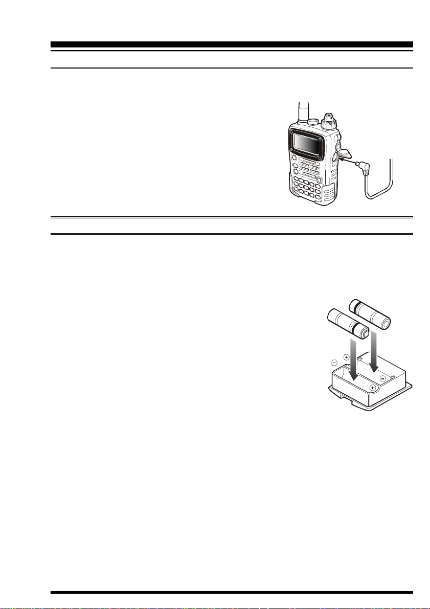
INSTALLATION OF FNB-80LI BATTERY PACK
If the battery has never been used, or its charge is depleted, it may be charged by connecting the NC-72B/C Battery Charger, as shown in the illustration, to the EXT DC jack. If
only 12 ~ 16 Volt DC power is available, the optional
E-DC-5B or E-DC-6 DC Adapter (with its cigarette lighter
plug) may also be used for charging the battery, as shown
in the illustration.
The display will indicate “now charging” while the battery is being charged. When charging is finished, the display will change to indicate “complete” and the STROBE
indicator will glow blue.
E-DC-5B
E-DC-6
INSTALLATION OF FBA-23 ALKALINE BATTERY CASE (OPTION
The optional FBA-23 Battery Case allows receive monitoring using two “AA” size Alkaline batteries. Alkaline batteries can also be used for transmission in an emergency, but
power output will only be selectable 300 mW and 50 mW, and battery life will be shortened dramatically.
)
To Install Alkaline Batteries into the FBA-23
1. Slide the batteries into the FBA-23 as shown in the illustration,
with the Negative
connections inside the FBA-23.
2. Open the Battery Pack Latch on the bottom of the radio.
3. Install the FBA-23 as shown in the illustration, with the [+
side facing the bottom of the transceiver.
4. Close the Battery Pack Latch on the bottom of the radio.
The FBA-23 does not provide connections for charging, since Alkaline cells cannot be re-
charged. Therefore, the NC-72B/C, E-DC-5B, or E-DC-6 may safely be connected to the
EXT DC jack when the FBA-23 is installed.
Notes:
¦ The FBA-23 is designed for use only with AA-type Alkaline cells.
¦ If you do not use the VX-7R for a long time, remove the Alkaline batteries from the
FBA-23, as battery leakage could cause damage to the FBA-23 and/or the transceiver.
[–]
side of the batteries touching the spring
]
VX-7R OPERATING MANUAL 9
Page 12
INSTALLATION OF ACCESSORIES
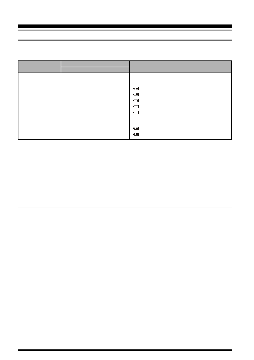
BATTERY LIFE INFORMATION
When the battery charge is almost depleted, a “Low Voltage” indicator will appear on the
display. When this icon appears, it is recommended that you charge the battery soon.
Operating Band
(1)
50 MHz
144 MHz
430 MHz
Other Band
(1) TX 6 sec., RX 6 sec. and Squelched 48 sec.
(2) Continuous signal reception
(1)
(1)
(2)
Battery Life (Approx.
FNB-80LI
6.5 hours
6.0 hours
5.5 hours
15 hours
The current battery voltage can be displayed manually on the LCD, by following the instructions on page 68.
Battery capacity may be reduced during extremely cold weather operation. Keeping the
radio inside your parka may help preserve the full charge capacity.
FBA-23
7.0 hours
6.5 hours
6.0 hours
15 hours
)
FNB-80LI:
No Icon: Fully battery power
FBA-23:
Low Voltage Indicator
: Enough battery power
: Lower battery power
: Poor battery power
: Nearing depletion
(
w/Blink): Prepare to charge the battery
: Enough battery power
(w/Blink): Prepare to replace the battery
AC OPERATION USING NC-72B/C (RECEIVING ONLY
)
The VX-7R may be operated from your house current by use of the supplied NC-72B/C
Battery Charger. The NC-72B/C should only be used for reception, because it is not capable of supplying sufficient current to support transmission.
To use the NC-72B/C, turn the transceiver off, then plug the miniature connector of the
Battery Charger into the EXT DC jack on the side of the radio. Now plug the Battery
Charger into the wall outlet. You may now turn on the transceiver.
VX-7R OPERATING MANUAL10
Page 13
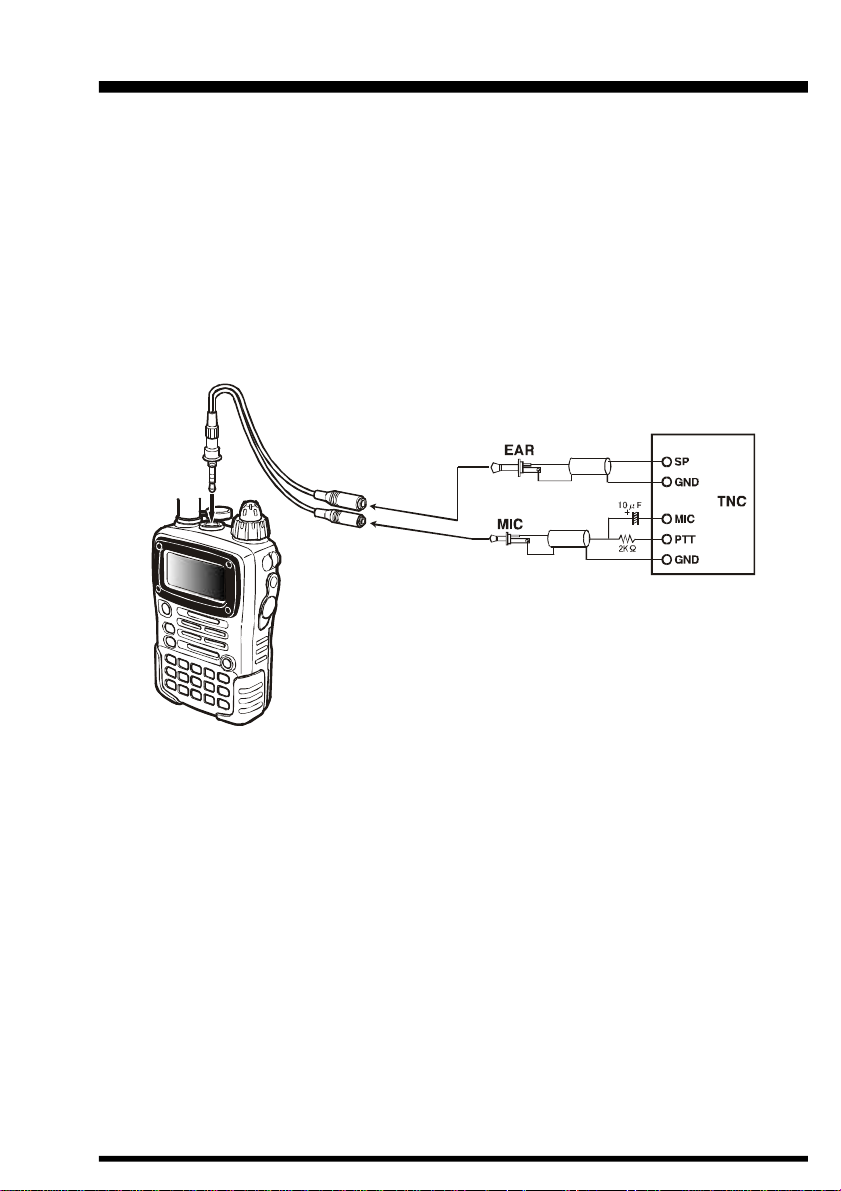
INTERFACE OF PACKET TNCS
The VX-7R may be used for Packet operation, using the optional CT-91 microphone adapter
(available from your Yaesu dealer) for easy interconnection to commonly-available connectors wired to your TNC. You may also build your own cable using a four-conductor
miniature phone plug, per the diagram below.
The audio level from the receiver to the TNC may be adjusted by using the VOLUME
knob, as with voice operation. The input level to the VX-7R from the TNC should be
adjusted at the TNC side; the optimum input voltage is approximately 5 mV at 2000 Ohms.
Be sure to turn the transceiver and TNC off before connecting the cables, so as to prevent
voltage spikes from possibly damaging your transceiver.
VX-7R OPERATING MANUAL 11
Page 14
OPERATION
Hi! I’m R. F. Radio, and I’ll be helping you along as you learn the many
features of the VX-7R. I know you’re anxious to get on the air, but I encour-
age you to read the “Operation” section of this manual as thoroughly as
possible, so you’ll get the most out of this fantastic new transceiver. Now. . .let’s get
operating!
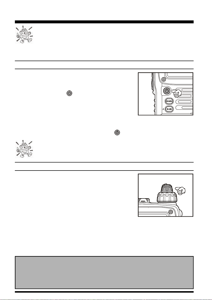
SWITCHING POWER ON AND OFF
1. Be sure the battery pack is installed, and that the battery
is fully charged. Connect the antenna to the top panel
ANTENNA jack.
2. Press and hold in the (PWR) switch (on the left side
of the front panel) for 2 seconds. Two beeps will be heard
when the switch has been held long enough, and the opening message will appear on the display, then frequency
display will appear. After another two seconds, the receive-mode Battery Saver function will become active, unless you have disabled it (see page 40).
3. To turn the VX-7R off, press and hold in the (PWR) switch again for 2 seconds.
If you don’t hear the two “Beep” tones when the radio comes on, the Beeper
may have been disabled via the Menu system. See page 24, which tells you
how to reactivate the Beeper.
ADJUSTING THE VOLUME LEVEL
Rotate the VOLUME control (inner knob) to set the desired
audio level. Clockwise rotation increases the volume level.
24-hour Clock
The VX-7R has a 24-hour clock with a calendar which covers all dates from January
1, 2000 through December 31, 2099. Set the clock according to the “Clock Set”
column on page 69.
VX-7R OPERATING MANUAL12
Page 15
OPERATION
SQUELCH ADJUSTMENT
The VX-7R’s Squelch system allows you to mute the background noise when no signal is
being received. Not only does the Squelch system make “standby” operation more pleasant, it also significantly reduces battery current consumption.
The Squelch system may be adjusted independently for the FM and Wide-FM (FM Broadcast) modes.
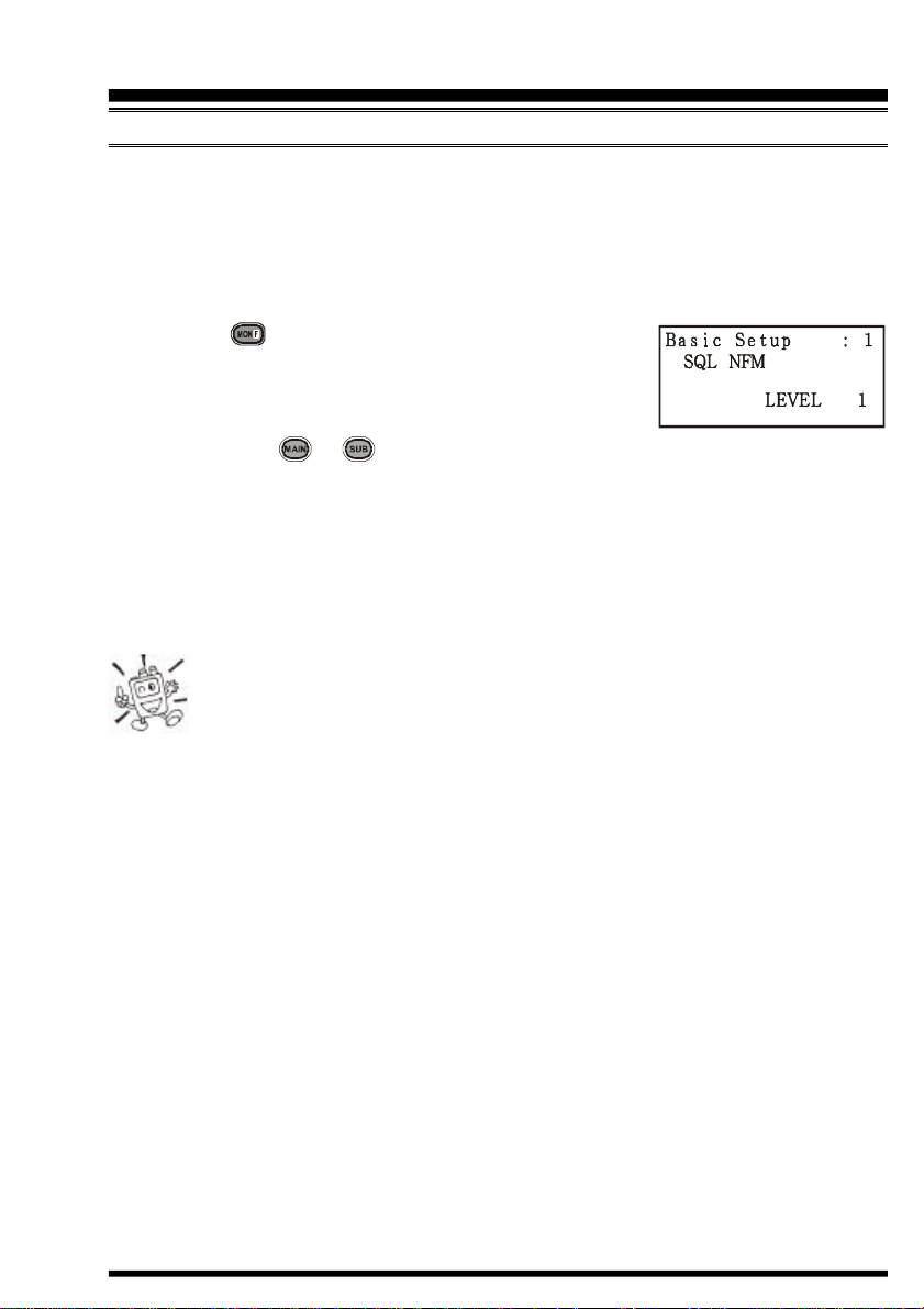
1. Press the key, then press the MONI switch on the left
side of the radio. This provides a “Short-cut” to Menu
Item (Basic Setup #1: SQL NFM) or Menu Item (Basic
Setup #2: SQL WFM).
2. Now, press the or key to set the background noise is just silenced (typically at
a setting of about “3” or “4” on the scale); this is point of maximum sensitivity to weak
signals.
3. When you are satisfied with the Squelch threshold setting, press the PTT key momentarily to save the new setting and exit to normal operation.
4. You may also adjust the Squelch setting by using the “Set” (Menu) mode. See page 82
for details.
1) The Squelch level may be set on the “Main” and “Sub” bands separately.
2) If you’re operating in an area of high RF pollution, you may need to
consider “Tone Squelch” operation using the built-in CTCSS Decoder. This
feature will keep your radio quiet until a call is received from a station sending a carrier
which contains a matching (subaudible) CTCSS tone. Or if your friends have radios
equipped with DCS (Digital Coded Squelch) like your VX-7R has, try using that mode
for silent monitoring of busy channels.
VX-7R OPERATING MANUAL 13
Page 16
OPERATION
SELECTING THE OPERATING BAND
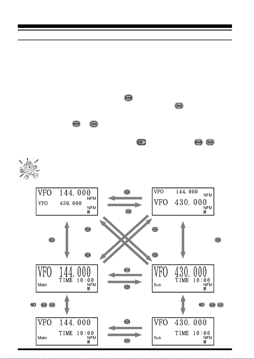
In the factory default configuration, the VX-7R operates in the “Dual Receive” mode.
During Dual Receive operation, the “Main” band frequency will be displayed on the upper
side of the LCD, and the “Sub” band frequency will be displayed on the lower side, with
the “Operating” band (the band on which transmission and band/frequency change are
possible) being indicated in large characters, and “Receive only” band being indicated in
small characters.
To switch the “Operating” band, press the key momentarily to engage the “Main”
band frequency as the “Operating” band. Alternatively, press the key momentarily to
engage the “Sub” band frequency as the “Operating” band, described previously.
Press and hold in the or key for 1/2 seconds to switch to Mono Band Operation
with a double-size display.
During Mono band operation, you may press the key, then press the / key, to
change the display to show only large characters.
The “Sub” band frequency may only be used on the amateur bands, even if it
is designated as the “Operating” band. Extended receiver coverage is only
possible on the “Main” band.
Press key
Press key
Press and hold
Press and hold key Press and hold key
Press and hold
Press Æ / key
key
key
Press key
Press key
Press key
Press key
Press and hold
key
Press and hold
key
Press Æ / key
VX-7R OPERATING MANUAL14
Page 17
OPERATION
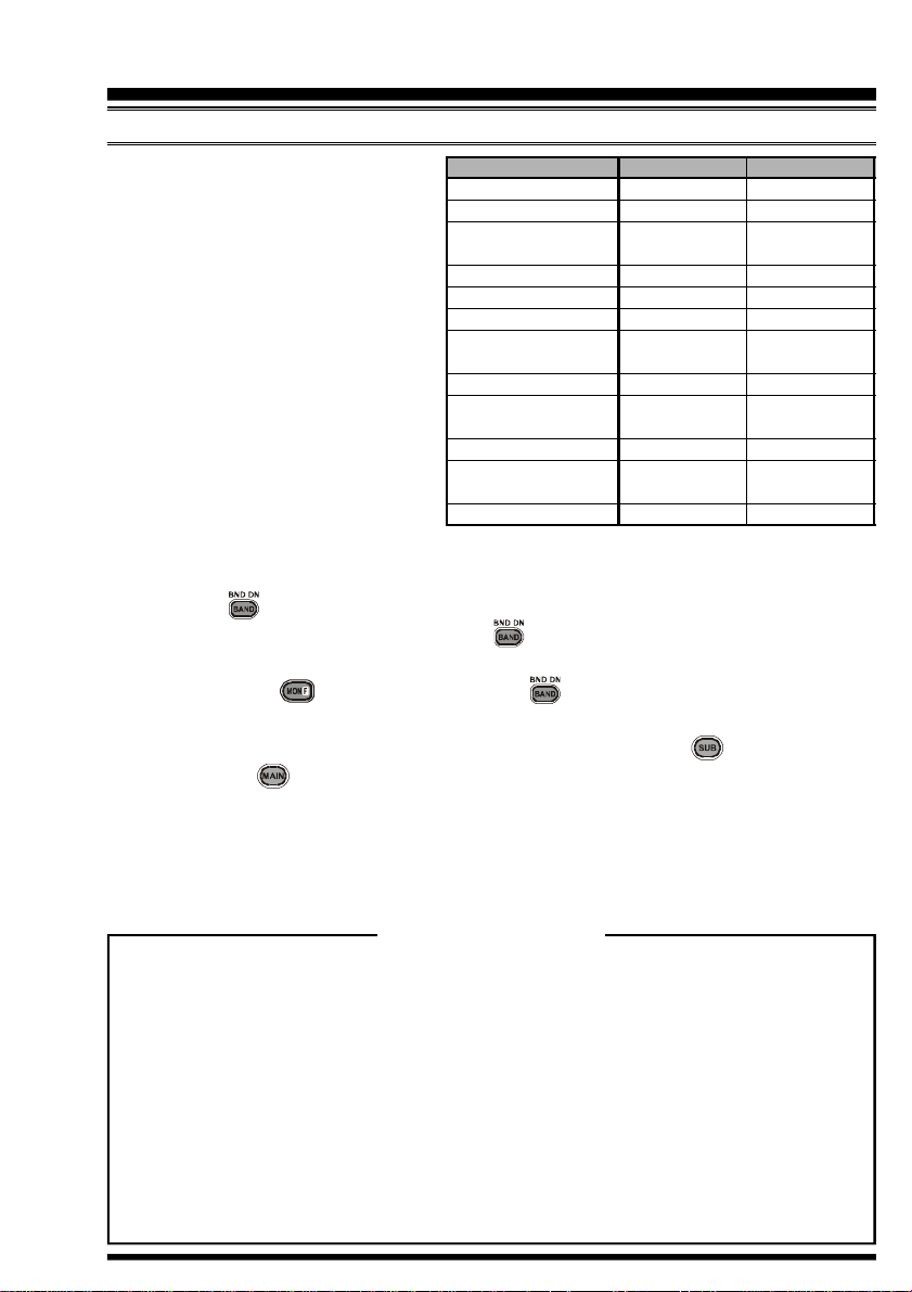
SELECTING THE FREQUENCY BAND
The VX-7R covers an incredibly wide
frequency range, over which a number
of different operating modes are used.
Therefore, the VX-7R’s frequency coverage has been divided into different
operating bands, each of which has its
own pre-set channel steps and operating modes. You can change the channel steps and operating modes later, if
you like (see page 25).
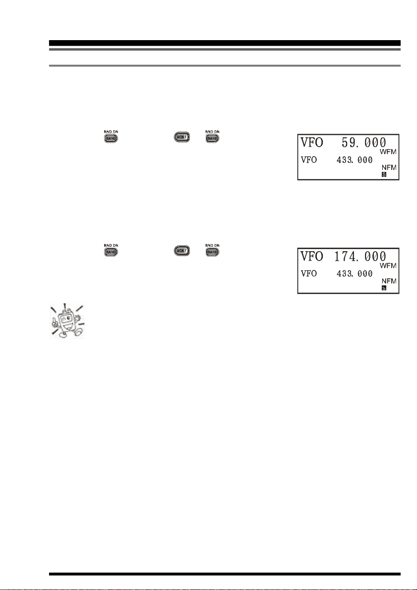
To Change Operating Bands
1. Press the key repetitively. You will see the LCD indication move toward a higher
frequency band each time you press the key. .
2. If you wish to move the operating band selection downward (toward lower frequen-
cies), press the key first, then press the key. .
3. The VX-7R uses a dual VFO system (described previously). To switch TX/RX opera-
tion from the “Main” VFO to the “Sub” VFO instantly, press the key momentarily. .
Pressing the key will return the VX-7R to the “Main” VFO. The frequency band
bearing the “Large” characters is the band on which transmission is possible; the band
designated by “Small” characters may only be used for reception.
4. Once you have selected the desired band, you may initiate manual tuning (or scanning)
per the discussions on the next page.
BAND
BC Band
SW Band
FM BC Band
AIR Band
VHF-TV Band
Action Band 1
UHF TV Band
Action Band 2
50 MHz Ham Band
144 MHz Ham Band
222 MHz Ham Band
430 MHz Ham Band
“Main” Band
0.5-1.8 MHz
1.8-30 MHz
59-108 MHz
(
88-108 MHz
108-137 MHz
174-222 MHz
225-420 MHz
470-729 MHz
(
470-800 MHz
800-999 MHz
30-59 MHz
(
30-88 MHz
137-174 MHz
222-225 MHz
420-470 MHz
(—)
)
)
)
( )
“Sub” Band
—
—
—
—
—
—
—
—
50-54 MHz
140-174 MHz
—
420-470 MHz
: EXP Version
Dual Receive Notice
The VX-7R may receive very strong signals on the Image frequency, and/or the
receiver sensitivity may be somewhat reduced by the combination of the “Main”
and “Sub” band frequencies while Dual Receive operation is engaged.
If you experience interference that you suspect may be coming in via an “Image”
path, you may calculate the possible frequencies using the formulas below. This information may be used in the design of effective countermeasures such as traps, etc.
¦ 3.579545 MHz x n ¦ 11.7 MHz x n (n is an integer: 1, 2, 3, …)
¦ “Main” band freq. = (“Sub” band freq. ± 46.35 MHz) x n
¦ “Sub” band freq. = (“Main” band freq. ± 47.25 MHz) x n (@ “Main band = NFM)
¦ “Sub” band freq. = (“Main” band freq. ± 45.8 MHz) x n (@ “Main band = WFM)
VX-7R OPERATING MANUAL 15
Page 18
OPERATION
FREQUENCY NAVIGATION
The VX-7R will initially be operating in the “VFO” mode, as just described. This is a channelized
system which allows free tuning throughout the currently-selected operating band.
Three basic frequency navigation methods are available on the VX-7R:
1) Tuning Dial (Outer ring of dual control on Top Panel)
Rotation of the DIAL allows tuning in the pre-programmed steps established for the current operating band. Clockwise rotation of the DIAL causes the VX-7R to be tuned toward
a higher frequency, while counter-clockwise rotation will lower the operating frequency.
If you press the key momentarily, then rotate the DIAL, frequency steps of 1 MHz will
be selected. This feature is extremely useful for making rapid frequency excursions over
the wide tuning range of the VX-7R.
2) Direct Keypad Frequency Entry
The desired operating frequency may be entered directly from the keypad.
The operating mode will automatically be set once the new frequency is entered via the
keypad.
To enter a frequency from the keypad, just press the numbered digits on the keypad in the
proper sequence. There is no “Decimal point” key on the VX-7R, so if the frequency is below
100 MHz (e.g. 15.150 MHz), any required leading zeroes must be entered. However, there is
a short-cut for frequencies ending in zero - press the key after the last non-zero digit.
Examples:
To enter 146.520 MHz, press à à à à à
To enter 15.255 MHz, press à à à à à
To enter 1.250 MHz (1250 kHz), press à à à à à
To enter 0.950 MHz (950 kHz), press à à à à à
To enter 430.000MHz, press à à
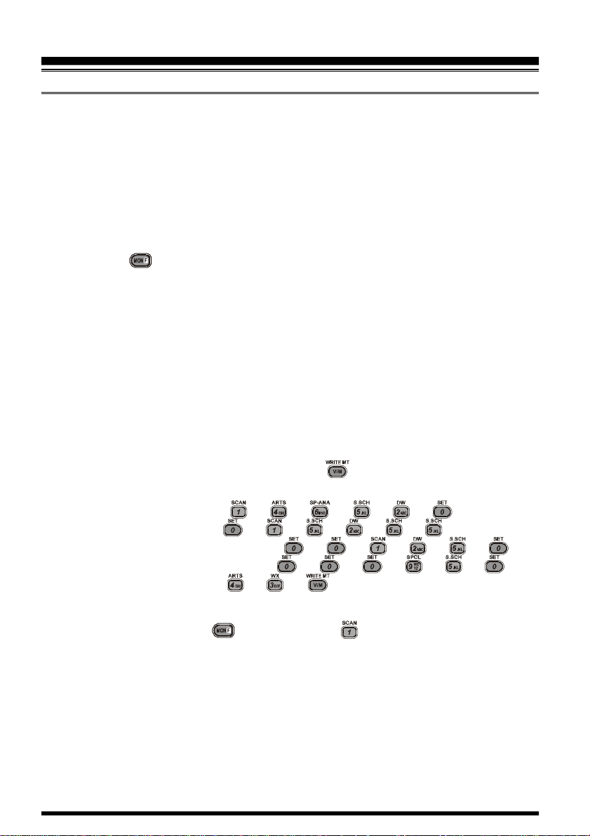
3) Scanning
From the VFO mode, press the key, then press the key. The VX-7R will begin scanning toward a higher frequency, and will stop when it receives a signal strong enough to break
through the Squelch threshold. The VX-7R will then hold on that frequency according to the
setting of the “RESUME” mode (Menu Item: Scan Modes #3). See page 57 for details.
If you wish to reverse the direction of the scan (i.e. toward a lower frequency, instead of a
higher frequency), just rotate the DIAL one click in the counter-clockwise direction while
the VX-7R is scanning. The scanning direction will be reversed. To revert to scanning
toward a higher frequency once more, rotate the DIAL one click clockwise.
Press the PTT switch momentarily to cancel the scanning.
VX-7R OPERATING MANUAL16
Page 19
OPERATION
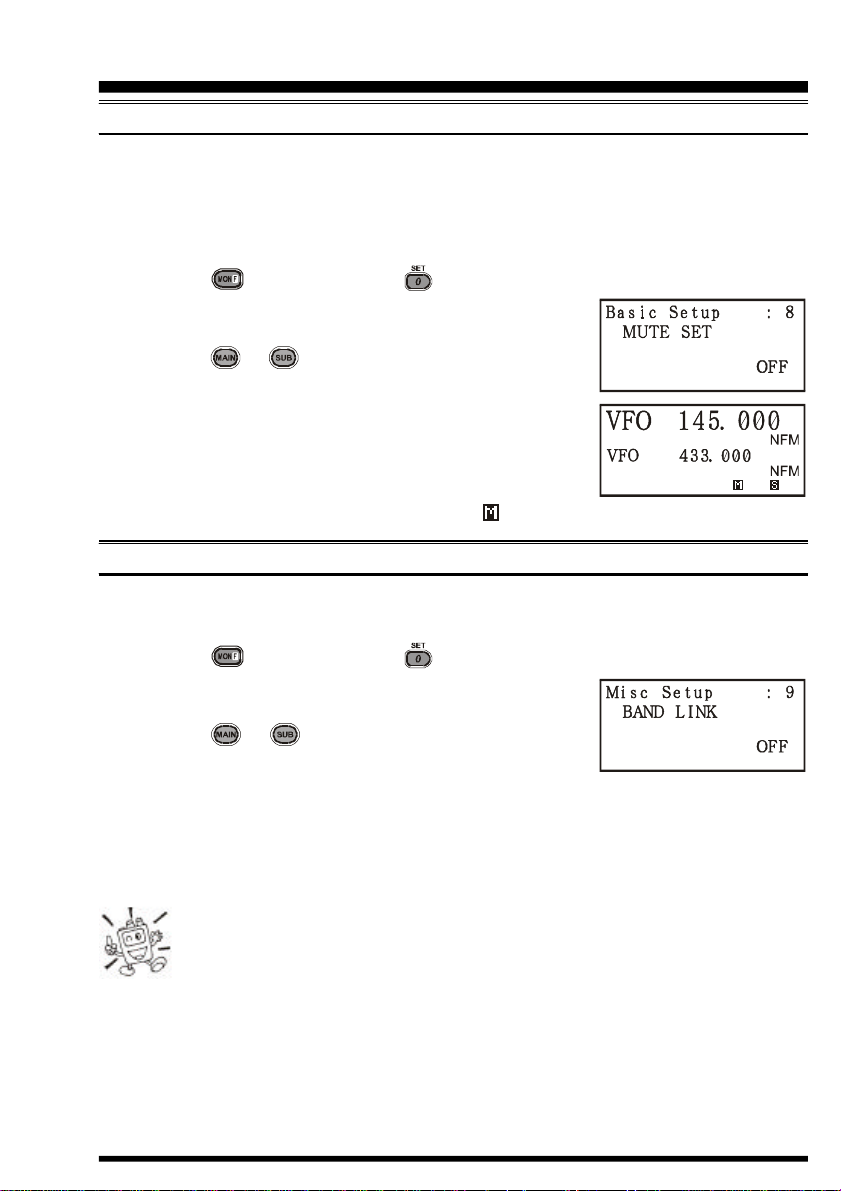
AUDIO MUTING
The Audio Mute feature is useful in situations where it would be helpful to reduce the
audio level of the “Receive Only” band (Small character display) whenever you receive a
signal on the “Main” band (Large character display) during Dual Receive operation.
To activate the Audio Mute feature:
1. Press the key, then press the key to enter the Set mode.
2. Rotate the DIAL to select the Menu Item labeled (Basic
Operation #8: MUTE SET).
3. Press the or key to select “ON” (to enable Audio
Mute feature).
4. Press the PTT switch to save the new setting and exit to
normal operation.
5. To disable the Audio Mute feature, select “OFF” in step 3
above.
When the Audio Mute feature is activated, the “ ” icon will appear on the display. .
BAND LINKING
For split operation on Amateur bands, the BAND Link feature may be useful.
1. Set up dual receive operation, as just described.
2. Press the key, then press the key to enter the Set mode.
3. Rotate the DIAL to select the Menu Item labeled (Misc
Setup #9: BAND LINK).
4. Press the or key to set this Menu Item to ON.
5. Press the PTT key to save the new setting and exit to
Linked/Dual receive operation.
As you rotate the DIAL, you will observe that both bands’ frequencies are changing together. When you are done with this operating mode, re-enter the Set mode, and set (Misc
Setup #9: BAND LINK) to OFF.
The BAND Link feature requires that (1) “Main” band and “Sub” band be
set to same band (Dual In-band receive), (2) Menu Item (Misc Setup #10:
VFO MODE) must be set to “BAND.” In other words, the BAND Link feature
cannot activated if “Main” band and “Sub” band are not set to the same band, or if
Menu Item (Misc Setup #10: VFO MODE) is set to “ALL.”
VX-7R OPERATING MANUAL 17
Page 20
OPERATION
TRANSMISSION
Once you have set up an appropriate frequency inside one of the three (or four) Amateur
bands on which the VX-7R can transmit (50 MHz, 144 MHz, or 430 MHz, plus 222 MHz
on the USA version), you’re ready to transmit. These are the most basic steps; more advanced aspects of transmitter operation will be discussed later.
1. To transmit, press the PTT switch, and speak into the front panel microphone (located
in the upper right-hand corner of the speaker grille) in a normal voice level. The
“STROBE” will glow red during transmission.
2. To return to the receive mode, release the PTT switch.
3. During transmission, the relative power level will be indicated on the LCD. Full power
(5 Watts) is indicated by eight arrows below the frequency display. The three “Low
Power” levels (L1, L2, and L3) are indicated by two, four, or six arrows, respectively.
Additionally, the “L1,” “L2,” or “L3” icon will appear at the bottom of the display,
corresponding with the “Low Power” Level setting.
If you’re just talking to friends in the immediate area, you’ll get much longer
battery life by switching to Low Power operation. To do this, press the
key, then press the key so that the “L” icon appears at the bottom of the
display. And don’t forget: always have an antenna connected when you transmit.
Transmission is not possible on any operating bands other than the 50 MHz, 144 MHz, 222
MHz, and 430 MHz bands.
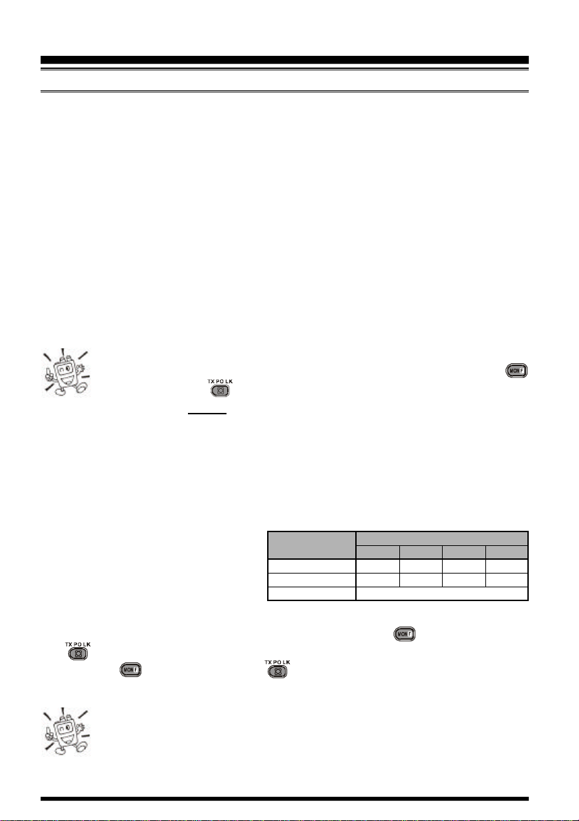
Changing the Transmitter Power Level
You can select between a total of four transmitter power levels on your VX-7R. The exact
power output will vary somewhat, depending on the voltage supplied to the transceiver.
With the standard FNB-80LI Battery
Pack and external DC source, the power
output levels available are:
To change the power level:
50/144/430 MHz
222 MHz FM
50 MHz AM
NONE
5.0 W
–
ICONS
L3
2.5 W
1.0 W
–
0.3 W
1.0 W (Fixed
L2
L1
0.05 W
0.05 W
)
1. The default setting for the power output is “High;” in this configuration, the LCD
shows no indication of the power output level. Pressing the key, followed by the
key, causes the power level “L1,” “L2,” or “L3” to appear..
2. Press the key, followed by the key (repeatedly, if necessary) to make the
“Low Power” icon disappear and restore High Power operation.
1) The VX-7R is smart! You can set up Low power on one band (like UHF),
while leaving VHF on High power, and the radio will remember the different
settings on each band. And when you store memories, you can store High
and Low power settings separately in each memory, so you don’t waste battery power
when using very close-in repeaters!
VX-7R OPERATING MANUAL18
Page 21
OPERATION
TRANSMISSION
2) When you are operating on one of the Low power settings, you can press the key,,
then press the PTT switch, to cause the VX-7R to transmit (temporarily) on High power.
After one transmission, the power level will revert to the previously-selected Low power
setting.
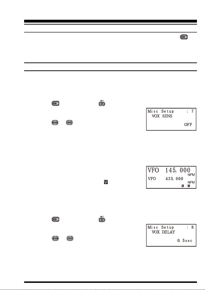
VOX OPERATION
The VOX system provides automatic transmit/receive switching based on voice input to
the microphone. With the VOX system enabled, you do not need to press the PTT switch
in order to transmit, and it is not necessary to use a VOX headset in order to utilize VOX
operation.
1. Press the key, then press the key to enter the Set mode.
2. Rotate the DIAL to select the Menu Item labeled (Misc
Setup #7: VOX SENS).
3. Press the or key to select the desired VOX Gain
level (“HIGH” or “LOW”).
4. When you have made your choice, press the PTT key to save the new setting and
return to normal operation.
5. Without pressing the PTT switch, speak into the microphone in a normal voice level.
When you start speaking, the transmitter should be activated automatically. When you
finish speaking, the transceiver should return to the receive mode (after a short delay).
6. To cancel VOX and return to PTT operation, just repeat
the above procedures, selecting “OFF” in step 3 above.
When the VOX system is activated, the “ ” icon will appear
on the display.
The VX-7R provides for adjustment of the “Hang-Time” of the VOX system (the transmitreceive delay after the cessation of speech) via the Menu. The default delay is 1/2 second.
To set a different delay time:
1. Press the key, then press the key to enter the Set mode.
2. Rotate the DIAL to select the Menu Item labeled (Misc
Setup #8: VOX DELAY).
3. Press the or key to select the delay time among
“0.5sec,” “1sec,” and “2sec.”
4. When you have made your choice, press the PTT key to save the new setting and
return to normal operation.
VX-7R OPERATING MANUAL 19
Page 22
OPERATION
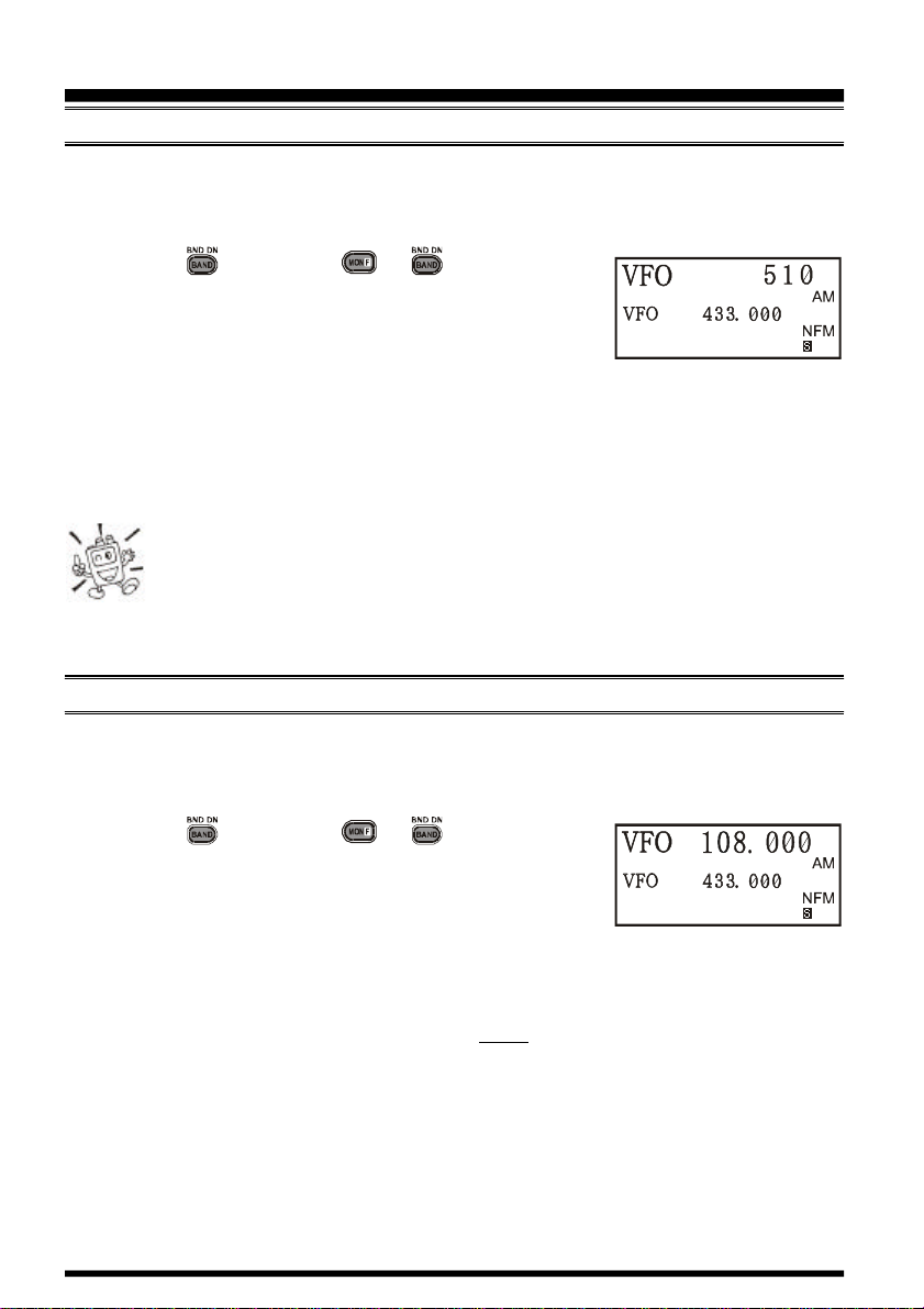
AM BROADCAST RECEPTION
The VX-7R includes provision for reception of AM broadcasts, either on the standard
medium-wave (MW) broadcast band, or on the shortwave bands up to 16 MHz.
1. Set the VX-7R to the VFO mode on the “Main” band.
2. Press the key (or press à ) repetitively until
you see a frequency in the frequency range desired. The
MW coverage is 0.5 MHz to 1.8 MHz, while the shortwave broadcast coverage is 1.8 MHz to 16 MHz. In either
case, the operating mode (displayed on the right edge of the LCD) should be shown as
being “AM.”
3. Rotate the DIAL to tune across the broadcast band.
4. You may also use the keypad to enter frequencies directly. This method will be quicker
for changing from the 49-meter broadcast band to the 31-meter band, for example.
1) If the operating mode is not correct, you may need to adjust the setting of
the Menu Item labeled (Basic Setup #4: RX MODE). See page 26 for details.
2) The VX-7R includes a special memory bank into which the factory has
stored 89 frequencies representing popular Short-wave Broadcast stations. See page 55
for details.
AM AIRCRAFT RECEPTION
Reception of AM signals in the aeronautical band (108-137 MHz) is similar to that described in the previous section.
1. Be sure that the VX-7R is set to the VFO mode on the “Main” band.
2. Press the key (or press à ) repetitively until
you see a frequency in the aeronautical band.
3. Rotate the DIAL to tune across the aeronautical band.
4. You may also use the keypad to enter frequencies directly.
Remember that frequencies quoted by aircraft operators may be abbreviated, and that
the “5” at the end of a frequency may be dropped. Since aeronautical channels are
assigned in 25-kHz steps, therefore, a frequency announced as “thirty-two, forty-two”
corresponds to an operating frequency of 132.425 MHz.
VX-7R OPERATING MANUAL20
Page 23
OPERATION
FM BROADCAST/TV AUDIO RECEPTION
The VX-7R also includes provision for reception in the FM broadcast band, utilizing a
wide-bandwidth filter which provides excellent fidelity.
To Activate FM Broadcast Reception
1. Be sure that the VX-7R is set to the VFO mode on the “Main” band.
2. Press the key (or press à ) repetitively until
a frequency in the FM broadcast band appears on the display. The total frequency range included in the “FM” band
is 59-108 MHz.
3. Rotate the DIAL to select the desired station. The default synthesizer steps for the WFM mode are 100 kHz/step.
To Activate VHF or UHF TV Audio Reception
1. Be sure that the VX-7R is set to the VFO mode on the “Main” band.
2. Press the key (or press à ) repetitively until
a frequency in the VHF or UHF TV bands appears on the
LCD.
3. Rotate the DIAL to select the desired station.
Remember that the Wide-FM Squelch setting may be made independently
from the Narrow-FM setting, using the Menu Item labeled (Basic Setup #2:
SQL WFM). See page 84.
VX-7R OPERATING MANUAL 21
Page 24
OPERATION
WEATHER BROADCAST RECEPTION
The VX-7R includes a unique feature which allows reception of weather broadcasts in the
160-MHz frequency range. Ten standard Weather Broadcast channels are pre-loaded into
a special memory bank.
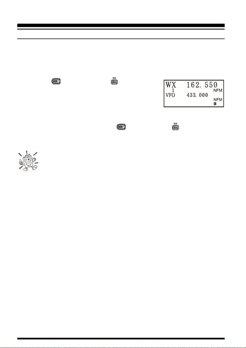
To listen to a Weather Broadcast Channel or VHF Marine Channel:
1. Press the key, then press the key to recall the
Weather Broadcast channels.
2. Turn the DIAL knob to select the desired Weather Broadcast channel.
3. If you wish to check the other channels for activity by scanning, just press the PTT
switch.
4. To exit to normal operation, again the key, then press the key. Operation will
return to the VFO or Memory channel you were operating on before you began Weather
Broadcast operation.
In the event of extreme weather disturbances, such as storms and hurricanes,
the NOAA (National Oceanic and Atmospheric Administration) sends a
weather alert accompanied by a 1050 Hz tone and subsequent weather report
on one of the NOAA weather channels. You may disable the Weather Alert tone via
Menu Item (Misc Setup #20 WX ALERT), if desired.
VX-7R OPERATING MANUAL22
Page 25
OPERATION
KEYBOARD LOCKING
In order to prevent accidental frequency change or inadvertent transmission, various aspects of the VX-7R’s keys and switches may be locked out. The possible lockout combinations are:
KEY: Just the front panel keys are locked out
DIAL: Just the top panel DIAL is locked out
KEY+DIAL: Both the DIAL and Keys are locked out
PTT: The PTT switch is locked (TX not possible)
KEY+PTT: Both the keys and PTT switch are locked out
DIAL + PTT:Both the DIAL and PTT switch are locked out
ALL: All of the above are locked out
To lock out some or all of the keys:
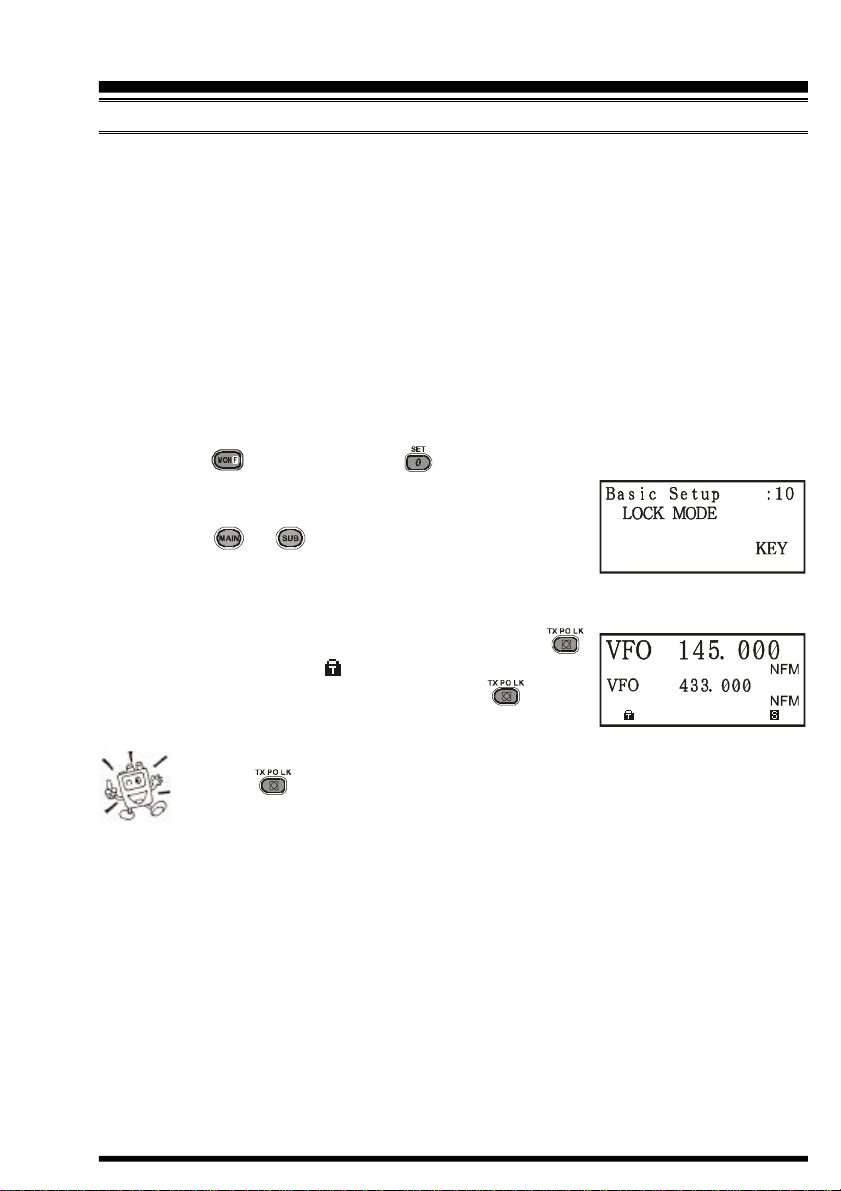
1. Press the key, then press the key to enter the Set mode.
2. Rotate the DIAL to select the Menu Item labeled (Basic
Setup #10: LOCK MODE).
3. Press the or key to choose between one of the
locking schemes as outlined above.
4. When you have made your selection, press the PTT switch to save the new setting and
resume normal operation.
5. To activate the locking feature, press and hold in the
key for 2 seconds. The “ ” icon will appear on the LCD.
To cancel locking, again press and hold the key for
2 seconds.
Even when “ALL” keys have been locked out, one key actually is not locked
out: the key remains available so you can unlock your keypad when you
want to!
VX-7R OPERATING MANUAL 23
Page 26
OPERATION
KEYPAD/LCD ILLUMINATION
Your VX-7R includes a reddish illumination lamp which aids in nighttime operation. The
red illumination yields clear viewing of the display in a dark environment, with minimal
degradation of your night vision. Three options for activating the lamp are provided:
KEY Mode: Illuminates the Keypad/LCD for 5 seconds when any key pressed.
CONTINUE Mode: Illuminates the Keypad/LCD continuously.
OFF Mode: Disables the Keypad/LCD lamp.
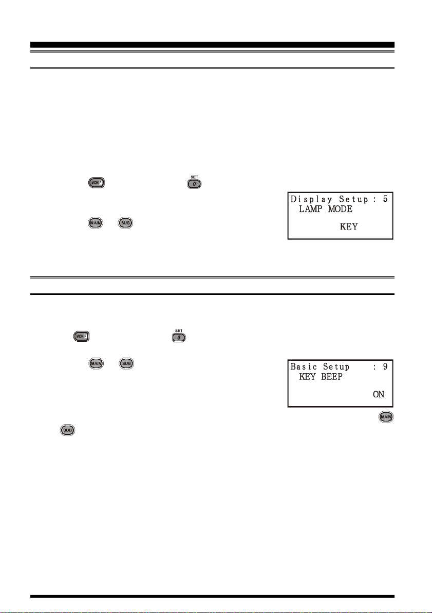
Here is the procedure for setting up the Lamp mode:
1. Press the key, then press the key to enter the Set mode.
2. Rotate the DIAL to select the Menu Item labeled (Display
Setup #5: LAMP MODE).
3. Press the or key to select one of the three modes
described above.
4. When you have made your choice, press the PTT key to save the new setting and
return to normal operation.
DISABLING THE KEYPAD BEEPER
If the keypad’s Beeper creates an inconvenience (particularly when operating in a quiet
room), it may easily be disabled.
1. Press key, then press the key to enter the Set mode.
2. Rotate the DIAL to select the Menu Item labeled (Basic Setup #9: KEY BEEP).
3. Press the or key to change the setting from ON
to OFF.
4. When you have made your selection, press the PTT key
to save the new setting and exit to normal operation.
5. If you wish to re-enable the Beeper, just repeat the above procedure, pressing the
or key to select ON in step “3” above.
VX-7R OPERATING MANUAL24
Page 27
ADVANCED OPERATION
Now that you’re mastered the basics of VX-7R operation, let’s learn more about some of
the really neat features.
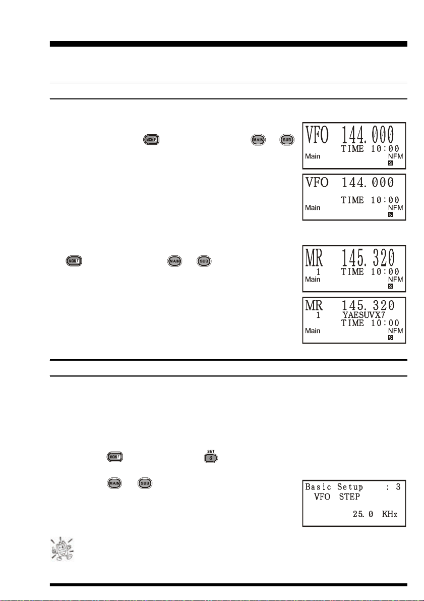
SETTING THE FREQUENCY DISPLAY IMAGE SIZE
VFO Mode
When operating in the VFO mode during the “Mono” band
operation, pressing the key, then pressing the or
key, causes the LCD to “toggle” between display of double-
size characters and large characters. However, this feature does
not work during Dual Receive operation, as two frequencies
are displayed in that instance.
Memory Mode
When operating in the Memory mode (see page 45), pressing
the key, followed by the or key, causes the LCD
to “toggle” between display of the current memory’s frequency
(in double-size characters) and the current memory’s frequency
(in large characters) with its alpha-numeric Tag (small characters). This feature likewise does not activate during Dual
Receive operation.
CHANGING THE CHANNEL STEPS
The VX-7R’s synthesizer provides the option of utilizing channel steps of 5/9/10/12.5/15/
20/25/50/100 kHz per step, any number of which may be important to your operating
requirements. The VX-7R is set up at the factory with different default steps on each operating band which probably are satisfactory for most operation. However, if you need to
change the channel step increments, the procedure to do so is very easy.
1. Press the key, then press the key to enter the Set mode.
2. Rotate the DIAL to select the Menu Item labeled (Basic Setup #3: VFO STEP).
3. Press the or key to select the new channel step
size.
4. Press the PTT key to save the new setting and exit to normal operation.
9 kHz step is available on the BC band only.
VX-7R OPERATING MANUAL 25
Page 28
ADVANCED OPERATION
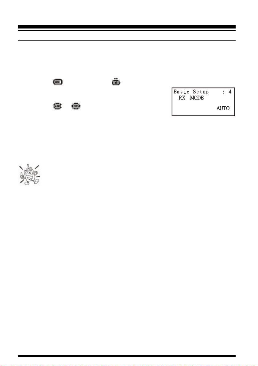
CHANGING THE OPERATING MODE
The VX-7R provides for automatic mode changing when the radio is tuned to different
operating frequencies. However, should an unusual operating situation arise in which you
need to change between the available operating modes (FM-Narrow, FM-Wide, and AM),
here is the procedure for doing so:
1. Press the key, then press the key to enter the Set mode.
2. Rotate the DIAL to select the Menu Item labeled (Basic
Setup #4: RX MODE).
3. Press the or key to select the new channel step
size. The available selections are:
AUTO: Automatic mode setting per default values for the selected frequency range..
N-FM: Narrow-bandwidth FM (used for voice communication)
W-FM: Wide-bandwidth FM (used for high-fidelity broadcasting)
AM: Amplitude Modulation
4. Press the PTT key to save the new setting and exit to normal operation.
Unless you have a compelling reason to do so, leave the Automatic Mode
Selection feature on so as to save time and trouble when changing bands. If
you make a mode change for a particular channel or station, you can always
store that one channel into memory, as the mode setting will be memorized along with
the frequency information.
VX-7R OPERATING MANUAL26
Page 29
ADVANCED OPERATION
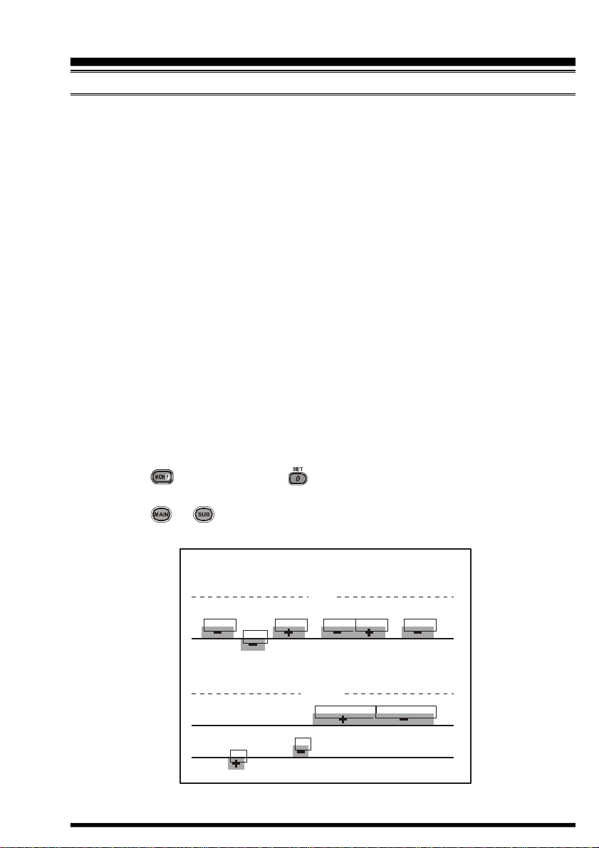
440.0
445.0
450.0
439.45
ARS-Repeater Subbands
REPEATER OPERATION
Repeater stations, usually located on mountaintops or other high locations, provide a dramatic extension of the communication range for low-powered hand-held or mobile transceivers. The VX-7R includes a number of features which make repeater operation simple
and enjoyable.
Repeater Shifts
Your VX-7R has been configured, at the factory, for the repeater shifts customary in your
country. For the 50 MHz band, this usually will be 1 MHz, while the 144 MHz shift will be
600 kHz; on 70 cm, the shift may be 1.6 MHz, 7.6 MHz, or 5 MHz (USA version).
Depending on the part of the band in which you are operating, the repeater shift may be
either downward (–) or upward (+), and one of these icons will appear at the bottom of the
LCD when repeater shifts have been enabled.
Automatic Repeater Shift (ARS)
The VX-7R provides a convenient Automatic Repeater Shift feature, which causes the
appropriate repeater shift to be automatically applied whenever you tune into the designated repeater sub-bands in your country. These sub-bands are shown below.
If the ARS feature does not appear to be working, you may have accidentally disabled it.
To re-enable ARS:
1. Press the key, then press the key to enter the Set mode.
2. Rotate the DIAL to select the Menu Item labeled (Basic Setup #5: ARS).
3. Press the or key to select “ON” (to enable Automatic Repeater Shift).
4. Press the PTT key to save the new setting and exit to normal operation.
VX-7R OPERATING MANUAL 27
145.1 145.5
145.6 145.8
Version A
433.00 433.40
2-m
Version A
146.0 146.4 147.0 147.6 148.0
146.6 147.4
European Version
70-cm
438.20
Euro Version 2
Euro Version 1
Page 30
ADVANCED OPERATION
REPEATER OPERATION
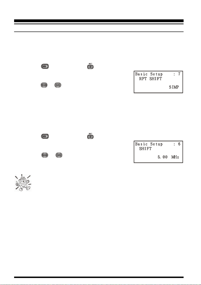
Manual Repeater Shift Activation
If the ARS feature has been disabled, or if you need to set a repeater shift direction other
than that established by the ARS, you may set the direction of the repeater shift manually.
To do this:
1. Press the key, then press the key to enter the Set mode.
2. Rotate the DIAL to select the Menu Item labeled (Basic
Setup #7: RPT SHIFT).
3. Press the or key to select the desired shift among
“–RPT,” “+RPT,” and “SIMP.”
4. Press the PTT key to save the new setting and exit to normal operation.
Changing the Default Repeater Shifts
If you travel to a different region, you may need to change the default repeater shift so as to
ensure compatibility with local operating requirements.
To do this, follow the procedure below:
1. Press the key, then press the key to enter the Set mode.
2. Rotate the DIAL to select the Menu Item labeled (Basic
Setup #6: SHIFT).
3. Press the or key to select the new repeater shift
magnitude.
4. Press the PTT key to save the new setting and exit to normal operation.
If you just have one “odd” split that you need to program, don’t change the
“default” repeated shifts using this Menu Item! Enter the transmit and re-
ceive frequencies separately, as shown on page 46.
VX-7R OPERATING MANUAL28
Page 31

ADVANCED OPERATION
REPEATER OPERATION
Checking the Repeater Uplink (Input) Frequency
It often is helpful to be able to check the uplink (input) frequency of a repeater, to see if the
calling station is within direct (“Simplex”) range.
To do this, just press the key. You’ll notice that the display has shifted to the repeater
uplink frequency. Press the key again to cause operation to revert to normal monitor-ing of the repeater downlink (output) frequency.
The configuration of this key may be set either to “RV” (for checking the inut
frequency of a repeater, or “HM” (for instant switching to the “Home” channel for the band you are operating on). To change the configuration of this
key, use Menu Item (Misc. Setup #2 HOM/REV). See page 49.
VX-7R OPERATING MANUAL 29
Page 32

ADVANCED OPERATION
CTCSS OPERATION
Many repeater systems require that a very-low-frequency audio tone be superimposed on
your FM carrier in order to activate the repeater. This helps prevent false activation of the
repeater by radar or spurious signals from other transmitters. This tone system, called
“CTCSS” (Continuous Tone Coded Squelch System), is included in your VX-7R, and is
very easy to activate.
CTCSS setup involves two actions: setting the Tone Frequency and then set-
ting of the Tone Mode. These actions are set up by using the key, or Menu
Items (TSQ/DCS/DTMF #1: SQL TYPE) and (TSQ/DCS/DTMF #2: TONE SET).
1. Press the key, then press the key. This provides a “Short-cut” to Menu Item
(TSQ/DCS/DTMF #1: SQL TYPE).
2. Press the or key so that “TONE” appears on the
display; this activates the CTCSS Encoder, which allows
repeater access.
You may notice an additional “DCS” icon appearing while you press the
or key in this step. We’ll discuss the Digital Code Squelch sys-
tem shortly.
3. Pressing the key in step “2” above will occasionally cause “SQL” to appear adja-
cent to the “TONE.” When “TONE SQL” appears, this means that the Tone SQueLch
system is active, which mutes your VX-7R’s receiver until it receives a call from another radio sending out a matching CTCSS tone. This can help keep your radio quiet
until a specific call is received, which may be helpful while operating in congested
areas.
4. When you have made your selection of the CTCSS tone
mode, rotate the DIAL one click clockwise to select Menu
Item labeled (TSQ/DCS/DTMF #2: TONE SET). This Menu
selection allows setting of the CTCSS tone frequency to
be used.
5. Press the key to enable the adjustment of the CTCSS frequency. .
6. Press the or key until the display indicates the Tone Frequency you need to be
using (ask the repeater owner/operator if you don’t know the tone frequency).
7. When you have made your selection, press the key, then press the PTT switch to
save the new settings and exit to normal operation.
Your repeater may or may not re-transmit a CTCSS tone - some systems just
use CTCSS to control access to the repeater, but don’t pass it along when
transmitting. If the S-Meter deflects, but the VX-7R is not passing audio,
repeat steps “1” through “3” above, but rotate the DIAL so that “SQL” disappears - this
will allow you to hear all traffic on the channel being received.
VX-7R OPERATING MANUAL30
Page 33

ADVANCED OPERATION
DCS OPERATION
Another form of tone access control is Digital Code Squelch, or DCS. It is a newer, more
advanced tone system which generally provides more immunity from false paging than
does CTCSS. The DCS Encoder/Decoder is built into your VX-7R, and operation is very
similar to that just described for CTCSS. Your repeater system may be configured for
DCS; if not, it is frequently quite useful in Simplex operation if your friend(s) use transceivers equipped with this advanced feature.
Just as in CTCSS operation, DCS requires that you set the Tone Mode to DCS
and that you select a tone code.
1. Press the key, then press the key. This provides a “Short-cut” to Menu Item
(TSQ/DCS/DTMF #1: SQL TYPE).
2. Press the or key until “DCS” appears on the dis-
play; this activates the DCS Encoder/Decoder.
3. Now rotate the DIAL to select Menu Item (TSQ/DCS/
DTMF #3: DCS SET).
4. Press the key to enable the adjustment of the DCS
code.
5. Press the or key to select the desired DCS Code
(a three-digit number). Ask the repeater owner/operator if you don’t know DCS Code;
if you are working simplex, just set up the DCS Code to be the same as that used by
your friend(s).
6. When you have made your selection, press the key, then press the PTT switch to
save the new settings and exit to normal operation.
Remember that the DCS is an Encode/Decode system, so your receiver will
remain muted until a matching DCS code is received on an incoming transmission. Switch the DCS off when you’re just tuning around the band!
CTCSS TONE FREQUENCY (Hz
67.0 69.3 71.9 74.4 77.0 79.7
82.5 85.4 88.5 91.5 94.8 97.4
100.0 103.5 107.2 110.9 114.8 118.8
123.0 127.3 131.8 136.5 141.3 146.2
151.4 156.7 159.8 162.2 165.5 167.9
171.3 173.8 177.3 179.9 183.5 186.2
189.9 192.8 196.6 199.5 203.5 206.5
210.7 218.1 225.7 229.1 233.6 241.8
250.3 254.1 – – – –
)
023 025 026 031 032 036 043 047 051 053
054 065 071 072 073 074 114 115 116 122
125 131 132 134 143 145 152 155 156 162
165 172 174 205 212 223 225 226 243 244
245 246 251 252 255 261 263 265 266 271
274 306 311 315 325 331 332 343 346 351
356 364 365 371 411 412 413 423 431 432
445 446 452 454 455 462 464 465 466 503
506 516 523 526 532 546 565 606 612 624
627 631 632 654 662 664 703 712 723 731
732 734 743 754 – – – – – –
DCS CODE
VX-7R OPERATING MANUAL 31
Page 34

ADVANCED OPERATION
TONE SEARCH SCANNING
In operating situations where you don’t know the CTCSS or DCS tone being used by
another station or stations, you can command the radio to listen to the incoming signal and
scan in search of the tone being used. Two things must be remembered in this regard:
¦ You must be sure that your repeater uses the same tone type (CTCSS vs. DCS).
¦ Some repeaters do not pass the CTCSS tone; you may have to listen to the station(s)
transmitting on the repeater uplink (input) frequency in order to allow Tone Search
Scanning to work.
To scan for the tone in use:
1. Set the radio up for either CTCSS or DCS Decoder operation (see the previous discus-
sion). In the case of CTCSS, “TSQ” will appear on the display; in the case of DCS,
“DCS” will appear on the display.
2. Press the key, then press the key to enter the Set mode.
3. Rotate the DIAL to select the Menu Item labeled (TSQ/
DCS/DTMF #2: TONE SET) when TONE SQL is selected,
or Menu Item labeled (TSQ/DCS/DTMF #3: DCS SET)
during DCS operation.
4. Press the key to enable adjustment of the selected
Menu Item.
5. Press the key, then press the key to start scanning
for the incoming CTCSS or DCS tone/code.
6. When the radio detects the correct tone or code, it will halt on that tone/code, and
audio will be allowed to pass. Press the key to lock in that tone/code, then press
PTT to exit to normal operation.
If the Tone Scan feature does not detect a tone or code, it will continue to
scan indefinitely. When this happens, it may be that the other station is not
sending any tone. You can press the PTT switch to halt the scan at any time.
You also can press the MONI key during Tone Scanning to listen to the (muted) signal
from the other station. When you release the MONI key, Tone Scanning will resume after
about a second.
Tone Scanning works either in the VFO or Memory modes.
VX-7R OPERATING MANUAL32
Page 35

ADVANCED OPERATION
CTCSS/DCS BELL OPERATION
During CTCSS Decode or DCS operation, you may set up the VX-7R such that a ringing
“bell” sound alerts you to the fact that a call is coming in. Here is the procedure for activating the CTCSS/DCS Bell:
1. Set the transceiver up for CTCSS Decode (“Tone Squelch”) or DCS operation, as
described previously.
2. Adjust the operating frequency to the desired channel.
3. Press the key, then press the key to enter the Set mode.
4. Rotate the DIAL to select the Menu Item labeled (TSQ/DCS/DTMF #5: BELL).
5. Press the or key to set the desired number of
rings of the Bell. The available choices are 1, 3, 5 , or 8
rings, CONTINUE (continuous ringing), or OFF.
6. Press the PTT key momentarily to save the new setting
and exit to normal operation.
When you are called by a station whose transceiver is sending a CTCSS tone or DCS code
which matches that set into your Decoder, the Bell will ring in accordance to this programming.
SPLIT TONE OPERATION
The VX-7R can be operated in a Split Tone configuration via the Set mode.
1. Press the key, then press the key to enter the Set mode.
2. Rotate the DIAL to select the Menu Item labeled (TSQ/DCS/DTMF #6: SPLIT TONE ).
3. Press the or key to select ON (to enable the Split
Tone feature).
4. Press the PTT key momentarily to save the new setting
and exit to normal operation.
When the Split Tone feature is activated, you can see the following additional parameters
after the “DCS” parameter while selecting the Menu Item (TSQ/DCS/DTMF #1: SQL TYPE),:
D CODE: DCS Encode only (“ ” icon will appear while operating)
TONE DC: Encodes a CTCSS Tone and Decodes a DCS code
(the “ ” icon will appear during operation)
DC TONE: Encodes a DCS code and Decodes a CTCSS Tone
(the “ ” icon will appear during operation)
Select the desired operating mode from the selections shown above.
VX-7R OPERATING MANUAL 33
Page 36

ADVANCED OPERATION
TONE CALLING (1750 HZ
If the repeaters in your country require a 1750-Hz burst tone for access (typically in Europe), you can set the MONI key to serve as a “Tone Call” switch instead. To change the
configuration of this switch, we again use the Menu to help us.
1. Press the key, then press the key to enter the Set mode.
2. Rotate the DIAL to select the Menu Item labeled (Misc Setup #3 MON /T-CAL).
3. Press the or key to select “T-CALL” on the dis-
play.
4. Press the PTT key to save the new setting and exit to nor-
mal operation.
5. To access a repeater, press and hold in the MONI key for the amount of time specified
by the repeater owner/operator. The transmitter will automatically be activated, and a
1750-Hz audio tone will be superimposed on the carrier. Once access to the repeater
has been gained, you may release the MONI key, and use the PTT key for activating
the transmitter.
)
VX-7R OPERATING MANUAL34
Page 37

ADVANCED OPERATION
ARTS (AUTOMATIC RANGE TRANSPONDER SYSTEM
The ARTS feature uses DCS signaling to inform both parties when you and another ARTSequipped station are within communications range. This may be particularly useful during
Search-and Rescue situations, where is important to stay in contact with other members of
your group.
Both stations must set up their DCS codes to the same code number, then activate their
ARTS feature using the command appropriate for their radio. Alert ringers may be activated, if desired.
Whenever you push the PTT, or every 25 (or 15) seconds after ARTS is activated, your
radio will transmit a signal which includes a (subaudible) DCS
signal for about 1 second. If the other radio is in range, the
beeper will sound (if enabled) and the display will show “IN
RANGE” as opposed to the out of range display “OUT RANGE”
in which ARTS operation begins.
Whether you talk or not, the polling every 15 or 25 seconds
will continue until you de-activate ARTS. Every 10 minutes,
moreover, you can have your radio transmit your callsign via
CW, so as to comply with identification requirements. When ARTS is de-activated, DCS
will also be deactivated (if you were not using it previously in non-ARTS operation).
If you move out of range for more than one minute (four pollings), your radio will sense
that no signal has been received, three beeps will sound, and the display will revert to
“OUT RANGE.” If you move back into range, your radio will again beep, and the display
will change back to the “IN RANGE” indication.
)
During ARTS operation, your operating frequency will continue to be displayed, but no
changes may be made to it or other settings; you must terminate ARTS in order to resume
normal operation. This is a safety feature designed to prevent accidental loss of contact
due to channel change, etc.
Here is how to activate ARTS:
Basic ARTS Setup and Operation
1. Set your radio and the other radio(s) to the same DCS code number, per the discussion
on page 31.
2. Press the key, then press the key. You will observe the “OUT RANGE” display
on the LCD below the operating frequency. ARTS operation has now commenced.
3. Every 25 seconds, your radio will transmit a “polling” call to the other station. When
that station responds with its own ARTS polling signal, the display will change to “IN
RANGE” to confirm that the other station’s polling code was received in response to
yours.
VX-7R OPERATING MANUAL 35
Page 38

ADVANCED OPERATION
ARTS (AUTOMATIC RANGE TRANSPONDER SYSTEM
4. Press the key, then press the key to exit ARTS operation and resume normal
functioning of the transceiver.
ARTS won’t work if you have used the Lock feature to disable the PTT!
ARTS Polling Time Options
The ARTS feature may be programmed to poll every 25 seconds (default value) or 15
seconds. The default value provides maximum battery conservation, because the polling
signal is sent out less frequently. To change the polling interval:
1. Press the key, then press the key to enter the Set mode.
2. Rotate the DIAL to select the Menu Item labeled (ARTS #2: ARTS ITERVAL).
3. Press the or key to select the desired polling interval (15 or 25 seconds).
4. When you have made your selection, press the PTT key
to save the new setting and exit to normal operation.
ARTS Alert Beep Options
The ARTS feature allows two kinds of alert beeps (with the additional option of turning
them off), so as to alert you to the current status of ARTS operation. Depending on your
location and the potential annoyance associated with frequent beeps, you may choose the
Beep mode which best suits your needs. The choices are:
)
IN RANGE: The beeps are issued only when the radio first confirms that you are within
range, but does not re-confirm with beeps thereafter.
ALWAYS: Every time a polling transmission is received from the other station, the
alert beeps will be heard.
OFF: No alert beeps will be heard; you must look at the display to confirm
current ARTS status.
To set the ARTS Beep mode, use the following procedure:
1. Press the key, then press the key to enter the Set mode.
2. Rotate the DIAL to select the Menu Item labeled (ARTS #1: ARTS BEEP).
3. Press the or key to select the desired ARTS Beep
mode (see above).
4. When you have made your selection, press the PTT key
to save the new setting and exit to normal operation.
VX-7R OPERATING MANUAL36
Page 39

ADVANCED OPERATION
ARTS (AUTOMATIC RANGE TRANSPONDER SYSTEM
CW Identifier Setup
The ARTS feature includes a CW identifier, as discussed previously. Every ten minutes
during ARTS operation, the radio can be instructed to send “DE (your callsign) K” if this
feature is enabled. The callsign field may contain up to 16 characters.
Here’s how to program the CW Identifier:
1. Press the key, then press the key to enter the Set mode.
2. Rotate the DIAL to select the Menu Item labeled (ARTS
#3: CW ID).
3. Press the key to enable changing of this Menu item.
The “ ” indicator will blink on the LCD.
4. Press the or key to set the CW ID function to ON.
5. Rotate the DIAL one click clockwise to begin entry of the letters and numbers in your
callsign.
6. Press the key or keyboard to set the first letter or number in your callsign.
Example 1: Press the key to select any of the 7 available characters (including
the “slant bar” for portable stations); or
Example 2: Press the key repeatedly to toggle among the seven available charac-
ters associated with that key: A à B à C à a à b à c à 2
7. When the correct character has been selected, rotate the DIAL one click clockwise to
move on to the next character.
8. Repeat steps 6 and 7 as many times as necessary to complete your callsign. Note that
the “slant bar” (– • • – •) is among the available characters, should you be a “portable”
station.
9. Press the key to delete all data after the cursor that may have been previously
stored erroneously.
10. When you have entered your entire callsign, press the key to confirm the callsign,
then press the PTT key to save the settings and exit to normal operation.
)
You may check your work by monitoring the entere callsign. To do this, repeat
steps 1 - 3 above, then press the key..
VX-7R OPERATING MANUAL 37
Page 40

ADVANCED OPERATION
DTMF OPERATION
The VX-7R’s 16-button keypad allows easy DTMF dialing for Autopatch, repeater control, or Internet-link access purposes. Besides numerical digits [0] through [9], the keypad
includes the [*] and [#] digits, plus the [A], [B], [C], and [D] tones often used for repeater
control.
Manual DTMF Tone Generation
You can generate DTMF tones during transmission manually.
1. Press the PTT switch to begin transmission.
2. While transmitting, press the desired numbers on the keypad.
3. When you have sent all the digits desired, release the PTT key.
DTMF Autodialer
Nine DTMF Autodial memories are provided, allowing you to store telephone numbers for
autopatch use. You can also store short autopatch or Internet-link access code streams so as
to avoid having to send them manually.
Here is the DTMF Autodial storage procedure:
1. Press the key, then press the key to enter the Set mode.
2. Rotate the DIAL knob to select the Menu Item labeled
(TSQ/DCS/DTMF #8: DTMF SET).
3. Press the key to enable adjustment of this Menu Item.
4. Press the or key to select the DTMF Memory
register into which you wish to store this DTMF string.
5. Rotate the DIAL knob one click to begin DTMF Memory entry into the selected register.
6. Key in the DTMF digits you wish to store into this register. If needed, you may press
the key to store a “Pause” (rotate the DIAL one click clockwise to continue) or
press the key again to delete the previously-stored data after the cursor..
7. If you make a mistake, rotate the DIAL konb counterclockwise to back-space the cursor, re-enter the correct number.
8. Press the PTT switch to save the setting. To store other numbers, repeat this process,
using a different DTMF memory register.
VX-7R OPERATING MANUAL38
Page 41

ADVANCED OPERATION
DTMF OPERATION
To send the telephone number:
1. Press the key, then press the key to enter the Set mode.
2. Rotate the DIAL to select the Menu Item labeled (TSQ/DCS/DTMF #7: DTMF DI-
ALER).
3. Press the or key to set the DTMF Autodialer
function to the “ON” position.
4. Press the PTT switch to exit to normal operation and activate the DTMF Autodialer function (the “ ” icon will
appear).
5. In the Autodialer function mode, first press the PTT key,
then press the numerical key ( through ) corresponding to the DTMF memory string you wish to send. Once the string begins, you may
release the PTT key, as the transmitter will be held “on the air” until the DTMF string
is completed.
EMERGENCY CHANNEL OPERATION
The VX-7R includes an “Emergency” feature which may be useful if you have someone
monitoring on the same frequency as your transceiver’s UHF “Home” channel. See page
47 for details on setting the Home channel.
The “Emergency” feature is activated by pressing the key for 1/2 seconds.
When this is done, (A) the radio is placed on the UHF amateur band Home channel, (B) it
emits a loud “Alarm” sound (the volume is controlled by the VOLUME knob), (C) it
flashes the STROBE in sequential colors, (D) if you press the PTT key, you will disable
the Emergency feature temporarily; you can then transmit on the UHF Home channel, and
(E) two seconds after the PTT release, the Emergency feature will resume.
To disable the “Emergency” feature, press the key for 1/2 seconds or turn the radio Offf
by pressing and holding in the (PWR) switch for 2 seconds.
Use this feature if you are out for a walk and want a quick way of alerting a family member
as to a dangerous situation. The alarm sound may discourage an attacker and allow you to
escape.
1) Be sure to arrange with a friend or family member to be monitoring on the
same frequency, as there will be no identification sent via the Emergency
alarm sound. And do not transmit the alarm tone except in a true emergency!
2) The STROBE may be changed to another function via Menu Item (Misc Setup #5:
EMG SET); see page 94.
VX-7R OPERATING MANUAL 39
Page 42

ADVANCED OPERATION
ATT (FRONT END ATTENUATOR
The attenuator will reduce all signals (and noise) by 20 dB, and it may be used to make
reception more pleasant under extremely noisy conditions.
1. Press the key, then press the key to enter the Set mode.
2. Rotate the DIAL to select the Menu Item labeled (Misc Setup #18: ATT).
3. Press the or key to change the setting from OFF
to ON.
4. When you have made your selection, press the PTT key
to save the new setting and exit to normal operation.
5. If you wish to disable the attenuator, just repeat the above
procedure, pressing the or key to select OFF in
step “3” above.
When the attenuator is activated, the “ ” icon will
appear on the display.
)
RECEIVE BATTERY SAVER SETUP
An important feature of the VX-7R is its Receive Battery Saver, which “puts the radio to
sleep” for a time interval, periodically “waking it up” to check for activity. If somebody is
talking on the channel, the VX-7R will remain in the “active” mode, then resume its “sleep”
cycles. This feature significantly reduces quiescent battery drain, and you may change the
amount of “sleep” time between activity checks using the Menu System:
1. Press the key, then press the key to enter the Set mode.
2. Rotate the DIAL to select the Menu Item labeled (Save Modes #2: RX SAVE).
3. Press the or key to select the desired “sleep”
duration. The selections available are 200 ms, 300 ms,
500 ms, 1 second, and 2 seconds, or OFF. The default
value is 200 ms.
4. When you have made your selection, press the PTT key to save the new setting and
exit to normal operation.
When you are operating on Packet, switch the Receive Battery Saver OFF, as
the sleep cycle may “collide” with the beginning of an incoming Packet transmission, causing your TNC not to receive the full data burst.
VX-7R OPERATING MANUAL40
Page 43

ADVANCED OPERATION
TX BATTERY SAVER
The VX-7R also includes a useful Transmit Battery Saver, which will automatically lower
the power output level when the last signal received was very strong. For example, when
you are in the immediate vicinity of a repeater station, there generally is no reason to use
the full 5 Watts of power output in order to achieve full-quieting access to the repeater.
With the Transmit Battery Saver, the automatic selection of Low Power operation conserves battery drain significantly.
To activate the Transmit Battery Saver:
1. Press the key, then press the key to enter the Set mode.
2. Rotate the DIAL to select the Menu Item labeled (Save Modes #3: TX SAVE).
3. Press the or key to set this Menu Item to “ON”
(thus activating the Transmit Battery Saver).
4. When you have completed your selection, press the PTT
key to save the new setting and exit to normal operation.
DISABLING THE “STROBE”
Further battery conservation may be accomplished by disabling the “STROBE” while
receiving a signal (when the “STROBE” functions as a “BUSY” LED). Use the following
procedure:
1. Press the key, then press the key to enter the Set mode.
2. Rotate the DIAL to select the Menu Item labeled (Display Setup #1: BUSY LED).
3. Press the or key to set this Menu Item to “OFF”
(thus disabling the BUSY lamp).
4. Press the PTT key to save the new setting and exit to nor-
mal operation.
VX-7R OPERATING MANUAL 41
Page 44

ADVANCED OPERATION
AUTOMATIC POWER-OFF (APO) FEATURE
The APO feature helps conserve battery life by automatically turning the radio off after a
user-defined period of time within which there has been no dial or key activity.
The available selections for the time before power-off are 0.5/1/3/5/8 hours, as well as
APO Off. The default condition for the APO is OFF, and here is the procedure for activating it:
1. Press the key, then press the key to enter the Set mode.
2. Rotate the DIAL to select the Menu Item labeled (Save Modes #1: APO).
3. Press the or key to select the desired time period
after which the radio will automatically shut down.
4. Once you have made your selection, press the PTT key to
save the new setting and exit to normal operation.
When the APO is activated, the “ ” icon will appear at the
center bottom on the LCD. If there is no action by you within
the time interval programmed, the microprocessor will shut
down the radio automatically.
Just press and hold in the (PWR) switch for 2 seconds to turn the transceiver back on
after an APO shutdown, as usual.
TRANSMITTER TIME-OUT TIMER (TOT
The TOT feature provides a safety switch which limits transmission to a pre-programmed
value. This will promote battery conservation by not allowing you to make excessivelylong transmissions, and in the event of a stuck PTT switch (perhaps if the radio or a Speaker/
Mic is wedged between car seats) it can prevent interference to other users as well as
battery depletion. As configured at the factory the TOT feature is set to OFF, and here is the
procedure for activating it:
1. Press the key, then press the key to enter the Set mode.
2. Rotate the DIAL to select the Menu Item labeled (Save Modes #4: TOT).
3. Press the or key to set the Time-Out Timer to the
desired “Maximum TX” time (1 minute, 2.5 minutes, 5
minutes, or 10 minutes).
4. Once you’re made the selection you wish to use, press the
PTT key to save the new setting and exit to normal operation.
Since brief transmissions are the mark of a good operator, try setting up your
radio’s TOT feature for a maximum transmission time of 1 minute. This will
significantly improve battery life, too!
)
VX-7R OPERATING MANUAL42
Page 45

ADVANCED OPERATION
BUSY CHANNEL LOCK-OUT (BCLO
The BCLO feature prevents the radio’s transmitter from being activated if a signal strong
enough to break through the “noise” squelch is present. On a frequency where stations
using different CTCSS or DCS codes may be active, BCLO prevents you from disrupting
their communications accidentally (because your radio may be muted by its own Tone
Decoder). The default setting for the BCLO is OFF, and here is how to change that setting:
1. Press the key, then press the key to enter the Set mode.
2. Rotate the DIAL to select the Menu Item labeled (Misc Setup #1: BCLO).
3. Press the or key to set this Menu Item to “ON”
(thus activating the BCLO feature).
4. Press the PTT key to save the new setting and resume
normal operation.
)
MIC MONITOR
The MIC Monitor feature allows you to monitor your voice signal when using the optional
VC-27 Earpiece/Microphone.
1. Connect the VC-27 Earpiece/Microphone to the MIC/SP jack.
2. Press the key, then press the key to enter the Set mode.
3. Rotate the DIAL to select the Menu Item labeled (Misc Setup #19: MIC MONITOR).
4. Press the or key to set this Menu Item to “ON”
(thus activating the MIC Monitor feature). The VX-7R
exit from the Set mode.
5. The VX-7R’s internal microphone will now pick up the
sound around the transceiver, then output its to the VC-27 Earpiece/Microphone.
6. To disable the MIC Monitor feature, repeat steps 2 - 4, pressing the or key to
select “OFF,” then press the PTT key.
When this feature is activated without the VC-27 Earpiece/Microphone connected, the VX-7R will develop a howling “feedback” condition.
VX-7R OPERATING MANUAL 43
Page 46

ADVANCED OPERATION
CHANGING THE TX DEVIATION LEVEL
In many areas of the world, channel congestion has required that operating channels be
closely spaced. In such operating environments, it often is required that operators use
reduced deviation levels, so as to reduce the potential for interference to users on adjacent
channels. The VX-7R includes a simple method of accomplishing this:
1. Press the key, then press the key to enter the Set mode.
2. Rotate the DIAL to select the Menu Item labeled (Misc Setup #6: HALF DEVIATION).
3. Press the or key to change this setting to ON. In
this configuration (HALF DEVIATION active), the
transmitter’s deviation will be approximately ±2.5 kHz.
4. When you have made your selection, press the PTT key
to save the new setting and exit to normal operation.
The “normal” setting for the deviation (when this Menu Item is set to OFF) is
±5 kHz.
VX-7R OPERATING MANUAL44
Page 47

MEMORY MODE
MR450MR44
9
OTM3OTM2OTM1OTM0OTM9OTM8L20/U20L19/U19L4/U4L3/U3L2/U2L1/U
1
HYP0HYP1HYP2HYP3HYP8HYP
9
WX10WX9WX4WX3WX2WX1
The VX-7R provides a wide variety of memory system resources. These include:
r Regular Memory Channels, which made up of:
¦ 450 “Standard” memory channels, numbered “1” through “450.”
¦ 12 (USA version) or 11 (EXP version) Home channels, providing storage and
quick recall of one prime frequency on each operating band.
¦ 20 sets of band-edge memories also known as “Programmable Memory Scan”
channels, labeled “L1/U1” through “L20/U20.”
¦ Nine Memory Groups, labeled “MG1” through “MG9.” Each Memory Group can
be assigned 48 channels from the “standard” memory channel bank.
r Ten One-Touch Memory Channels
r Ten “Hyper-Memory” Channels
r Ten “Weather Broadcast” Channles
r 89 popular Short-wave Broadcast Station Memory Channels.
r 280 VHF Marine Channels.
Standard Memory Channels
(450 channels)
MR4
MR3
MR2
MR1
(USA: 12 channels, EXP: 11 channels)
HOME Channels
AIR Band
VHF-TV Band
FM BC Band
Action Band-1
(89 channels)
SW B and
BC Band
Short-wave Broadcast Station Memory Channels
One-Touch Memory Channels
(10 channels)
Weather Broadcast Channels
430 MHz Band
222 MHz Band
50 MHz Band
144 MHz Band
Action Band-2
UHF-TV Band
222 MHz Band:
USA version only
(10 channels)
PMS Memory Channels
Hyper Memory Channels
Marine Channels
(280 channels)
(20 Sets)
(10 channels)
VX-7R OPERATING MANUAL 45
Page 48

MEMORY MODE
REGULAR MEMORY CHANNEL OPERATION
Memory Storage
1. Select the desired frequency, while operating in the VFO mode. Be sure to set up any
desired CTCSS or DCS tones, as well as any desired repeater offset. The power level
may also be set at this time, if you wish to store it.
2. Press and hold in the key for 1/2 second.
3. Within five seconds of releasing the key, rotate the DIAL to select the desired
memory channel. The microprocessor will automatically select the next-available “free”
channel (a memory register on which no data has been
stored). If you see an Asterisk
ber, it means that the channel currently has no data written
on it (i.e. the channel is “free”.)
4. Press the key once more to store the frequency into memory. .
5. You still will be operating in the “VFO” mode, so you may now enter other frequencies, and store them into additional memory locations, by repeating the above process.
You may change the automatic memory channel selection feature to select
the “next-highest memory channel above the last-stored memory channel”
by instead of the “next-available ‘free’ channel” via the Menu Item labeled
(
Basic Setup #12 MW MODE); see page 85.
(Û)
by any channel num-
Storing Independent Transmit Frequencies (“Odd Splits”)
All memories can store an independent transmit frequency, for operation on repeaters with
non-standard shift. To do this:
1. Store the receive frequency using the method already described under MEMORY
STORAGE (it doesn’t matter if a repeater offset is active).
2. Turn to the desired transmit frequency, then press and hold in the key for 1/2
second.
3. Within five seconds of releasing the key, rotate the DIAL to select the same memory
channel number as used in step “1” above.
4. Press and hold in the PTT switch, then press the key once more momentarily
while holding the PTT switch in (this does not key the transmitter).
Whenever you recall a memory which contains independently-stored transmit
and receive frequencies, the “ ” indication will appear in the display..
VX-7R OPERATING MANUAL46
Page 49

MEMORY MODE
REGULAR MEMORY CHANNEL OPERATION
Memory Recall
1. While operating in the VFO mode, press the key to
enter the Memory mode.
2. Rotate the DIAL to select the desired channel.
3. To return to the VFO mode, press the key. .
1) When the radio is already set to the Memory mode, an easy way to recall
memories is to key in the memory channel number, then press the key..
For example, to recall memory channel #14, press à à .
2) Memory channels on which you may have stored frequencies outside the amateur
bands cannot be recalled on the SUB band.
HOME Channel Memory
A special one-touch “HOME” channel is available (one for
each of the 12 (USA version) or 11 (EXP version) operating
bands: see page 15), to allow quick recall of a favorite operating frequency on each band. Memory storage is simple to accomplish:
1. Select the desired frequency, while operating in the VFO mode. Be sure to set up any
desired CTCSS or DCS tones, as well as any desired repeater offset. The power level
may also be set at this time, if you wish to store it.
2. Press and hold in the key for 1/2 second.
3. While the memory channel number is blinking, just press the key. The frequency
and other data (if any) will now be stored in the special HOME channel register.
4. You may repeat this process on the other operating bands.
5. To recall the HOME channel, press the key, then press the key while operating either in the VFO or MR mode.
Note that the UHF HOME channel is the one used during “Emergency” operation. See page 39 for details regarding this feature.
VX-7R OPERATING MANUAL 47
Page 50

MEMORY MODE
REGULAR MEMORY CHANNEL OPERATION
Labeling Memories
You may wish to append an alpha-numeric “Tag” (label) to a memory or memories, to aid
in recollection of the channel’s use (such as a club name, etc.). This is easily accomplished
using the Set mode.
1. Recall the memory channel on which you wish to append a label.
2. Press the key, then press the key to enter the Set mode.
3. Rotate the DIAL to select the Menu Item labeled (Basic Setup #11: NAME SET).
4. Press the key momentarily to enable programming of
the name tag.
5. Press the / key, or one of the keyboard keys, to
select the first digit of the desired label.
Example 1: Press the key, then press the or key to select any of the 61
available characters.
Example 2: Press the key repeatedly to toggle among the seven available charac-
ters associated with that key: A à B à C à a à b à c à 2
6. Rotate the DIAL one click clockwise to move to the next character.
7. Repeat steps 4 and 5 to program the remaining letters,
numbers, or symbols of the desired label. A total of eight
characters may be used in the creation of a label.
8. When you have completed the creation of the label, press
the PTT key to save the label and exit.
During “MR” (Memory Recall) operation, the alphanumeric Tag will appear below the frequency
display. The alphanumeric Tag does not appear if
you activate the Dual Receive Operation.
VX-7R OPERATING MANUAL48
Page 51

MEMORY MODE
REGULAR MEMORY CHANNEL OPERATION
Memory Offset Tuning
Once you have recalled a particular memory channel, you may easily tune off that channel,
as though you were in the “VFO” mode.
1. With the VX-7R in the “MR” (Memory Recall) mode, select the desired memory chan-
nel.
2. Now press and hold in the key for 1/2 second. The “MR” indicator will be replaced by one which says “MT” (“Memory Tuning”).
3. Rotate the DIAL, as desired, to tune to a new frequency.
The synthesizer steps selected for VFO operation on the
current band will be the steps used during Memory Tuning.
4. If you wish to return to the original memory frequency, press and hold in the key
for 1/2 second. The “MT” indicator will be replaced by “MR.”
5. If you wish to store a new frequency set during Memory Tuning, just press and hold in
the key for 1/2 second, per normal memory storage procedure. The microprocessor will automatically set itself to the next-available clear memory location, and you
then press again to lock in the new frequency. .
If you want to replace the original memory contents with those of the new
frequency, be sure to rotate the DIAL to the original memory channel number!
Any required CTCSS/DCS changes, or repeater offset modifications, must be done before
storing the data into the new (or original) memory channel location.
VX-7R OPERATING MANUAL 49
Page 52

MEMORY MODE
REGULAR MEMORY CHANNEL OPERATION
Masking Memories
There may be situations where you want to “Mask” memories so they are not visible during
memory selection or scanning. For example, several memories used only in a city you visit
infrequently may be stored, then “Masked” until you visit that city, at which time you can
“Unmask” them for normal use.
1. Press the key, if needed, to enter the MR mode.
2. Press and hold in the key for 1/2 second, then rotate the DIAL to select the memory
channel to be “Masked” from view.
3. Press the key. The display will revert to memory channel #1. If you rotate the
DIAL to the location you just “Masked,” you will observe that it is now invisible.
4. To Unmask the hidden memory, repeat the above procedure: press and hold in the
key for 1/2 second, rotate the DIAL to select the masked memory’s umber, then press
to restore the memory channel’s data.
Watch out! You can manually store data over a “Masked” memory, deleting
previous data, if you’re not careful. Use the “next available memory” technique (look for the
memory.
[Û]
icon) storage technique to avoid over-writing a masked
VX-7R OPERATING MANUAL50
Page 53

MEMORY MODE
REGULAR MEMORY CHANNEL OPERATION
Memory Group Operation
Memory Group Assignment
1. Recall the memory channel to be assigned to a Memory Group.
2. Press and hold in the key for 1/2 seconds, then press the numbered key ( ~ )
you want as the Memory Group for this channel.
3. Now memory channel data is copied into the Memory Group.
Memory Group Recall
1. Set the radio to the Memory mode on the “Main” Band by pressing the key, if
necessary.
2. Press the key, then press the key to recall the
Special Memory Menu.
3. Rotate the DIAL knob to select the “2 MR Group” mode.
4. Press the PTT switch to activate the “Memory Group” mode.
5. Rotate the DIAL knob to select the desired Memory Group
(“MG1” ~ “MG9”).
6. Press the key momentarily to lock in the selected
Memory Group.
7. In the Memory Group mode of operation, you can only select memory channels in the
current memory group (up to 48 channels).
8. To change the Memory Group to another Group, press the key momentarily, then
rotate the DIAL knob.
9. To exit from Memory Group operation, recall the Special Memory Menu (press +
) then change its setting to “1 OFF.”
VX-7R OPERATING MANUAL 51
Page 54

MEMORY MODE
Moving Memory Data to the VFO
Data stored on memory channels can easily be moved to VFO, if you like.
1. Select the memory channel containing the frequency data to be moved to VFO.
2. Press and hold in the key for 1/2 second, then press the key. The data will
now have been copied to VFO, although the original memory contents will remain
intact on the previously-stored channel.
If a Split Frequency Memory channel was transferred, the Tx frequency will be
ignored (you will be set up for Simplex operation on the Receive frequency).
Memory Only Mode
Once memory channel programming has been completed, you may place the radio in a
“Memory Only” mode, whereby VFO operation is impossible. This may be particularly
useful during public-service events where a number of operators may be using the radio for
first time, and ultimate simplicity of channel selection is desired.
To place the radio into the Memory Only mode, turn the radio off. Now press and hold in
the key while turning the radio on.
To return to normal operation, repeat the above power-on procedure.
VX-7R OPERATING MANUAL52
Page 55

MEMORY MODE
HYPER MEMOR Y MODE
The VX-7R usually stores, into memory, the operating frequency and some aspects of
operating status (such as CTCSS/DCS data, repeater shift, power level etc.). However, the
“Hyper Memory” Mode allows you to store the total current configuration of the radio into
a special “Hyper” memory bank.
For example, a Hyper Memory location may store the frequencies of both the “Main” and
“Sub” bands, plus Spectrum Scope operational status, Scanning features, etc.
Hyper Memory Storage
1. Set up the transceiver according to the desired configuration, including parameters
such as Spectrum Scope operation, PMS scanning, etc.
2. Press and hold in the numeric key ( through ), corresponding to the Hyper
Memory channel into which you wish to store this configuration, for 2 seconds.
In order to prevent accidental storage, the Hyper Memory Storage feature may
be locked out via Menu Item (Basic Setup #14 HYPER WRITE).
Hyper Memory Recall
1. Press the key, then press the key, to recall the Special Memory Menu.
2. Rotate the DIAL konb to select the “4 HYP” mode.
3. Press the PTT switch to activate the “Hyper Memory”
mode.
4. Press the appropriate numeric key ( through ) to
recall the desired Hyper Memory channel.
5. To exit the Hyper Memory mode, recall the Special
Memory Menu (press + ), then change its setting
to “1 OFF.”
VX-7R OPERATING MANUAL 53
Page 56

MEMORY MODE
ONE-TOUCH MEMORY MODE
The One-Touch feature allows you to recall up to ten favorite frequencies directly via the
numeric ( through ) keys.
One-Touch Memory Storage
1. Select the desired frequency, while operating in the VFO mode. Be sure to set up any
desired CTCSS or DCS tones, as well as any desired repeater offset. The power level
may also be set at this time, if you wish to store it.
2. Press and hold in the key for 1/2 second.
3. Within five seconds of releasing the key, rotate the
DIAL to select the desired One-Touch Memory channel,
which will be labeled “OTM0” through “OTM9.”
4. Press the key once more to store the frequency into
the selected One-Touch Memory.
5. You still will be operating in the “VFO” mode, so you may now enter other frequencies, and store them into additional One-Touch Memory locations, by repeating the
above process.
One-Touch Memory Recall
1. Set the VX-7R to Mono band operation on the “Main” band.
2. Press the key, then press the key to recall the Special Memory Menu.
3. Rotate the DIAL knob to select the “3 OTM” mode.
4. Press the PTT switch to activate the “One-Touch Memory”
mode.
5. Press the numeric key ( through ) corresponding to
the One-Touch memory you wish to recall.
6. To exit the One-Touch Memory mode, recall the Special
Memory Menu (press + ), then change its setting
to “1 OFF.”
VX-7R OPERATING MANUAL54
Page 57

MEMORY MODE
SHORT-WAVE BROADCAST STATION MEMOR Y CHANNELS
The Short-wave Broadcast Station Memory Channel Bank has been pre-programmed at
the factory, for quick selection of broadcast stations.
1. Set the VX-7R to Mono band operation on the “Main” band.
2. Press the key, then press the key, to recall the
Special Memory Menu.
3. Rotate the DIAL knob to select the “5 BC Station” mode.
4. Press the PTT switch to activate the “BC Station” mode.
5. Rotate the DIAL to select any of the 89 available Broadcast Stations.
6. To exit the BC Station mode, recall the Special Memory
Menu (press + ), then change its setting to “1
OFF.”
BROADCAST STATION FREQUENCY LIST
LST
No.
Freq.
MODE
Tag
(MHz)
1
6.030
6.160
9.760
11.930
5.995
7.235
9.735
11.705
6.195
9.410
12.095
15.310
6.045
9.790
11.670
15.525
3.955
6.075
9.545
9.735
6.060
7.175
9.515
17.710
3.985
6.165
9.885
15.220
5.985
9.925
11.780
13.740
5.955
6.020
9.895
11.655
9.590
9.985
13.800
15.735
9.780
11.960
15.555
21.655
AM
AM
AM
AM
AM
AM
AM
AM
AM
AM
AM
AM
AM
AM
AM
AM
AM
AM
AM
AM
AM
AM
AM
AM
AM
AM
AM
AM
AM
AM
AM
AM
AM
AM
AM
AM
AM
AM
AM
AM
AM
AM
AM
AM
2
3
4
5
6
7
8
9
10
11
12
13
14
15
16
17
18
19
20
21
22
23
24
25
26
27
28
29
30
31
32
33
34
35
36
37
38
39
40
41
42
43
44
Station Name
VOA
Voice of America
VOA
Voice of America
VOA
Voice of America
VOA
Voice of America
Canada
Radio Canada International
Canada
Radio Canada International
Canada
Radio Canada International
Canada
Radio Canada International
BBC
British Broadcasting Corporation
BBC
British Broadcasting Corporation
BBC
British Broadcasting Corporation
BBC
British Broadcasting Corporation
France
Radio France International
France
Radio France International
France
Radio France International
France
Radio France International
DW
Deutsche Welle
DW
Deutsche Welle
DW
Deutsche Welle
DW
Deutsche Welle
Italy
Italian Radio International
Italy
Italian Radio International
Italy
Italian Radio International
Italy
Italian Radio International
Swiss
Swiss Radio International
Swiss
Swiss Radio International
Swiss
Swiss Radio International
Swiss
Swiss Radio International
Belgium
Radio Vlaanderen International
Belgium
Radio Vlaanderen International
Belgium
Radio Vlaanderen International
Belgium
Radio Vlaanderen International
Holland
Radio Nederland
Holland
Radio Nederland
Holland
Radio Nederland
Holland
Radio Nederland
Denmark
Radio Denmark
Denmark
Radio Denmark
Denmark
Radio Denmark
Denmark
Radio Denmark
Portugal
Radio Portugal
Portugal
Radio Portugal
Portugal
Radio Portugal
Portugal
Radio Portugal
LST
No.
45
46
47
48
49
50
51
52
53
54
55
56
57
58
59
60
61
62
63
64
65
66
67
68
69
70
71
72
73
74
75
76
77
78
79
80
81
82
83
84
85
86
87
88
89
Freq.
(MHz)
7.270
9.520
11.920
15.585
6.090
7.485
9.590
9.985
13.800
6.065
9.490
13.625
17.505
6.120
9.630
11.755
9.795
5.940
5.920
7.205
12.030
9.435
11.585
15.615
17.545
6.045
9.595
11.620
15.020
7.190
5.250
9.855
11.685
5.975
7.275
9.570
13.670
6.155
7.200
9.750
11.850
5.995
9.580
9.660
12080
MODE
AM
AM
AM
AM
AM
AM
AM
AM
AM
AM
AM
AM
AM
AM
AM
AM
AM
AM
AM
AM
AM
AM
AM
AM
AM
AM
AM
AM
AM
AM
AM
AM
AM
AM
AM
AM
AM
AM
AM
AM
AM
AM
AM
AM
AM
Tag
Station Name
Spain
Radio Exterior de Espana
Spain
Radio Exterior de Espana
Spain
Radio Exterior de Espana
Spain
Radio Exterior de Espana
Luxembrg
Radio Luxembourg
Norway
Radio Norway International
Norway
Radio Norway International
Norway
Radio Norway International
Norway
Radio Norway International
Sweden
Radio Sweden
Sweden
Radio Sweden
Sweden
Radio Sweden
Sweden
Radio Sweden
Finland
Radio Finland
Finland
Radio Finland
Finland
Radio Finland
Finland
Radio Finland
Russia
Voice of Russia
Russia
Voice of Russia
Russia
Voice of Russia
Russia
Voice of Russia
Israel
Israel Broadcasting Authority
Israel
Israel Broadcasting Authority
Israel
Israel Broadcasting Authority
Israel
Israel Broadcasting Authority
India
All India Radio (AIR)
India
All India Radio (AIR)
India
All India Radio (AIR)
India
All India Radio (AIR)
China
China Radio International (CRI)
China
China Radio International (CRI)
China
China Radio International (CRI)
China
China Radio International (CRI)
Korea
Radio Korea
Korea
Radio Korea
Korea
Radio Korea
Korea
Radio Korea
Japan
Radio Japan
Japan
Radio Japan
Japan
Radio Japan
Japan
Radio Japan
Australi
Radio Australia
Australi
Radio Australia
Australi
Radio Australia
Australi
Radio Australia
VX-7R OPERATING MANUAL 55
Page 58

MEMORY MODE
VHF MARINE MEMORY CHANNELS
The VHF Marine Channel Bank has been pre-programmed at the factory, for quick selection.
1. Set the VX-7R to Mono band operation on the “Main” band.
2. Press the key, then press the key, to recall the
Special Memory Menu.
3. Rotate the DIAL knob to select the “6 Marine” mode.
4. Press the PTT switch to activate the “VHF Marine Chan-
nel” mode.
5. Rotate the DIAL to select any of the 280 available VHF
Marine Channels.
6. To exit the VHF Marine Channel mode, recall the Special
Memory Menu (press + ), then change its setting to “1OFF.”
VHF MARINE CHANNEL FREQUENCY LIST
Frequency
CH
No.
156.000
0
156.050
1
156.100
2
156.150
3
156.200
4
156.250
5
156.300
6
156.350
7
156.400
8
156.450
9
156.500
10
156.550
11
156.600
12
156.650
13
156.700
14
156.750
15
156.800
16
156.850
17
156.900
18
156.950
19
157.000
20
157.050
21
157.100
22
157.150
23
157.200
24
157.250
25
157.300
26
157.350
27
157.400
28
157.450
29
157.500
30
157.550
31
157.600
32
157.650
33
157.700
34
157.750
35
157.800
36
157.850
37
157.900
38
157.950
39
158.000
40
(
MHz
CH
Frequency
)
No.
41
42
43
44
45
46
47
48
49
50
51
52
53
54
55
56
57
58
59
60
61
62
63
64
65
66
67
68
69
70
71
72
73
74
75
76
77
78
79
80
81
(
MHz
158.050
158.100
158.150
158.200
158.250
158.300
158.350
158.400
158.450
158.500
158.550
158.600
158.650
158.700
158.750
158.800
158.850
158.900
158.950
156.025
156.075
156.125
156.175
156.225
156.275
156.325
156.375
156.425
156.475
156.525
156.575
156.625
156.675
156.725
156.875
156.925
156.975
157.025
157.075
Frequency
CH
)
No.
157.125
82
157.175
83
157.225
84
157.275
85
157.325
86
157.375
87
157.425
88
157.475
89
157.525
90
157.575
91
157.625
92
157.675
93
157.725
94
157.775
95
157.825
96
157.875
97
157.925
98
157.975
99
158.025
100
158.075
101
158.125
102
158.175
103
158.225
104
158.275
105
158.325
106
158.375
107
158.425
108
158.475
109
158.525
110
158.575
111
158.625
112
158.675
113
158.725
114
158.775
115
–
–
116
117
118
119
120
121
122
158.825
158.875
158.925
158.975
159.000
159.025
159.050
(
MHz
CH
Frequency
)
No.
123
159.075
124
159.100
125
159.125
126
159.150
127
159.175
128
159.200
129
159.225
130
159.250
131
159.275
132
159.300
133
159.325
134
159.350
135
159.375
136
159.400
137
159.425
138
159.450
139
159.475
140
159.500
141
159.525
142
159.550
143
159.575
144
159.600
145
159.625
146
159.650
147
159.675
148
159.700
149
159.725
150
159.750
151
159.775
152
159.800
153
159.825
154
159.850
155
159.875
156
159.900
157
159.925
158
159.950
159
159.975
160
160.000
161
160.025
162
160.050
163
160.075
(
MHz
CH
Frequency
)
No.
164
160.100
165
160.125
166
160.150
167
160.175
168
160.200
169
160.225
170
160.250
171
160.275
172
160.300
173
160.325
174
160.350
175
160.375
176
160.400
177
160.425
178
160.450
179
160.475
180
160.500
181
160.525
182
160.550
183
160.575
184
160.600
185
160.625
186
160.650
187
160.675
188
160.700
189
160.725
190
160.750
191
160.775
192
160.800
193
160.825
194
160.850
195
160.875
196
160.900
197
160.925
198
160.950
199
160.975
200
161.000
201
161.025
202
161.050
203
161.075
204
161.100
(
MHz
CH
Frequency
)
No.
205
161.125
206
161.150
207
161.175
208
161.200
209
161.225
210
161.250
211
161.275
212
161.300
213
161.325
214
161.350
215
161.375
216
161.400
217
161.425
218
161.450
219
161.475
220
161.500
221
161.525
222
161.550
223
161.575
224
161.600
225
161.625
226
161.650
227
161.675
228
161.700
229
161.725
230
161.750
231
161.775
232
161.800
233
161.825
234
161.850
235
161.875
236
161.900
237
161.925
238
161.950
239
161.975
240
162.000
241
162.025
212
155.975
243
155.950
244
155.925
245
155.900
(
MHz
CH
Frequency
(
)
No.
246
247
248
249
250
251
252
253
254
255
256
257
258
259
260
261
262
263
264
265
266
267
268
269
270
271
272
273
274
275
276
277
278
279
280
281
MHz
155.875
155.850
155.825
155.800
155.775
155.750
155.725
155.700
155.675
155.650
155.625
155.600
155.575
155.550
155.525
155.500
155.475
155.450
155.425
155.400
155.375
155.350
155.325
155.300
155.275
155.250
155.225
155.200
155.175
155.150
155.125
155.100
155.075
155.050
155.025
155.000
)
VX-7R OPERATING MANUAL56
Page 59

SCANNING
The VX-7R allows you to scan just the memory channels, the entire operating band, or a
portion of that band. It will halt on signals encountered, so you can talk to the station(s) on
that frequency, if you like.
Scanning operation is basically the same in each of the above modes. Before you begin,
take a moment to select the way in which you would like the scanner to resume scanning
after it halts on a signal.
Setting the Scan-Resume Technique
Three options for the Scan-Resume mode are available:
3 SEC/5 SEC/10 SEC: In this mode, the scanner will halt on a signal it encounters, and
will hold there for the selected resume time. If you do not take
action to disable the scanner within that time period, the scanner
will resume even if the stations are still active.
BUSY: In this mode, the scanner will halt on a signal it encounters. Two
seconds after the carrier has dropped because the other station(s)
ceased transmission, the scanner will resume. In the case of constant-carrier signals like Weather Station broadcasts, the scanner
will likely remain on this frequency indefinitely.
HOLD: In this mode, the scanner will halt on a signal it encounters. It will
not restart automatically; you must manually re-initiate scanning
if you wish to resume.
To set the Scan-Resume mode:
1. Press the key, then press the key to enter the Set mode.
2. Rotate the DIAL to select the Menu Item labeled (Scan Modes #3: RESUME).
3. Press the or key to select the desired scan-resume mode.
4. When you have made your selection, press the PTT key
to save the new setting and exit to normal operation.
The default condition for this Menu Item is “5 SEC.”
Setting the Squelch Level during active Scanning operation
The VX-7R allows adjustment of the Squelch level “on the fly” while you are scanning.
1. While the scanner is engaged, press the key, then press the key (the current
squelch level will appear below the frequency display).
2. Rotate the DIAL to select the desired Squelch level.
3. Press the PTT switch momentarily to save the new setting
and exit to normal operation. In this case, pressing the
PTT switch this one time will not causing scanning to stop.
VX-7R OPERATING MANUAL 57
Page 60

SCANNING
VFO SCANNING
This mode allows you to scan the entire current operating band.
1. Select the VFO mode by pressing the key, if necessary. .
2. Press the key, then press the key to start scanning.
3. If and when the scanner encounters a signal strong enough to open the squelch, the
scanner will halt temporarily; the decimal point of the frequency display will blink
during this “Pause” condition.
4. The scanner will then resume according to the Scan-Resume mode selected in the
previous section.
5. To cancel scanning, press the PTT or key. .
When you start scanning, the VX-7R will be changing frequency in the upward direction. If you want to change direction of the scan while it is underway, rotate the DIAL one click in the opposite direction (in this case, one click
counter-clockwise). You’ll see the scanner turn around and change frequency downward!
You may change the scanning operation so that the VFO frequency will jump to the low
band edge of the next band when the VFO frequency reaches the high edge of the current
band (or vice versa). See page 95 regarding Menu Item (Misc Setup #10 VFO MODE).
MEMORY SCANNING
Memory scanning is similarly easy to initiate:
1. Set the radio to the Memory mode by pressing the key, if necessary. .
2. Press the key, then press the key to initiate scanning.
3. As with VFO scanning, the scanner will halt on any signal encountered that is strong
enough to open the squelch; it will then resume scanning according to the Scan-Resume mode set previously.
4. To cancel scanning, press the PTT or key. .
On the “Sub” band, Memory Channel scan will search through only the memory
channels which are stored inside the amateur bands.
VX-7R OPERATING MANUAL58
Page 61

SCANNING
MEMORY SCANNING
Temporary Memory Skip
If the scanner repeatedly stops on a channel due to temporary noise or interference, you
can temporarily mark it to be skipped (except for Memory Channel “1”). The channel will
be skipped until you manually stop the scan (by pressing the PTT switch, for example).
To skip a channel temporarily, press the key, then press the key while the scanner
has stopped on the channel to be skipped. The scanner will instantaneously resume, and
that channel will not be scanned during this scanning session.
How to Skip (Omit) a Channel During Memory Scan Operation
As mentioned previously, some continuous-carrier stations like a Weather Broadcast station will seriously impede scanner operation if you are using the “Carrier Drop” ScanResume mode, as the incoming signal will not pause long enough for the transceiver to
resume scanning. Such channels may be “Skipped” during scanning, if you like:
1. Set the radio to the Memory Mode by pressing the key, if necessary. .
2. Rotate the DIAL to select the Memory Channel to be skipped during scanning.
3. Press the key, then press the key to enter the Set mode.
4. Rotate the DIAL to select the Menu Item labeled (Basic
Setup #13: MEMO SCAN MODE).
5. Press the or key so as to select “SKIP.” The cur-rent Memory Channel will now be ignored during scanning. The “PREFERENTIAL” selection is used for “Preferential Memory Scan,” described in the next column.
6. When you have made your selection, press the PTT key to save the settings and exit to
normal operation.
A small “t” icon will appear when you recall the “skipped”
memory channel manually.
To re-institute a channel into the scanning loop, select “OFF”
in step 5 above (the “Skipped” channel will, of course, still be
accessible via manual channel selection methods using the DIAL in the MR mode, whether
or not it is locked out of the scanning loop).
VX-7R OPERATING MANUAL 59
Page 62

SCANNING
MEMORY SCANNING
Preferential Memory Scan
The VX-7R also allows you to set up a “Preferential Scan List” of channels which you can
“flag” within the memory system. These channels are designated by a “ ” icon when you
have selected them, one by one, for the Preferential Scan List. When you initiate memory
scanning on a channel with the “ ” icon appended, only those channels bearing the “ ”
icon will be scanned. If you initiate scanning on a channel which does not have the “ ”
icon appended, you will scan all channels including those with the “ ” icon appended.
1) Here is the procedure for setting up and using the Preferential Scan List:
1. Press the key momentarily to enter the Memory Recall mode, if you are not using
memories already.
2. Rotate the DIAL to select the channel which you wish to add to the Preferential Scan
List.
3. Press the key, then press the key to enter the Set mode.
4. Rotate the DIAL to select the Menu Item labeled (Basic Setup #13: MEMO SCAN
MODE).
5. Press the or key so as to select “PREFERENTIAL.”
6. When you have made your selection, press the PTT key to
save the settings and exit to normal operation.
2) To initiate Preferential Memory Scan:
1. Press the key momentarily to enter the Memory Recall mode, if you are not using
memories already.
2. Rotate the DIAL to select any channel which has an “ ”
icon appended to the channel number.
3. Press the key, then press the key to initiate Preferential Memory Scanning. Only the channels which have
an “ ” icon appended to the channel number will be scanned.
VX-7R OPERATING MANUAL60
Page 63

SCANNING
PROGRAMMABLE (BAND LIMIT) MEMORY SCAN (PMS
This feature allows you to set sub-band limits for either scanning or manual VFO operation. For example, you might with to set up a limit (in North America) of 144.300 MHz to
148.000 MHz so as to prevent encroachment into the SSB/CW “Weak Signal” portion of
the band below 144.300 MHz. Here’s how to do this:
1. Set the radio to the VFO mode by pressing the key, if necessary. .
2. Using the techniques learned earlier, store (per the above
concept) 144.300 MHz into Memory Channel #L1 (the
“L” designates the Lower sub-band limit).
3. Likewise, store 148.000 MHz into Memory Channel #U1
(the “U” designates the Upper sub-band limit).
4. Switch to the Memory mode by pressing the key once, then rotate the DIAL to
select Memory Channel # L1.
5. Press and hold in the key for 1/2 second to start PMS
operation; the “MR” label will be replaced by “PMS” in
the upper left-hand corner of the display. Tuning and canning will now be limited within the just-programmed range.
6. 20 pairs of Band Limit memories, labeled L1/U1 through L20/U20 are available. You
therefore can set upper and lower operation limits on a number of bands, if you like.
“PRIORITY CHANNEL” SCANNING (DUAL WATCH
The VX-7R’s scanning features include a two-channel scanning capability which allows
you to operate on a VFO or Memory channel, while periodically checking a user-defined
Memory Channel for activity. If a station is received on the Memory Channel which is
strong enough to open the Squelch, the scanner will pause on that station in accordance
with the Scan-Resume mode set via Menu Item (Scan Modes #3: RESUME). See page 56.
)
)
Here is the procedure for activating Priority Channel Dual Watch operation:
1. Press the key momentarily to enter the Memory Recall mode, if you are not using
memories already.
2. Press and hold in the key for 1/2 second, then select the memory channel you
wish to be the “Priority” channel.
3. Press the key. When rotate the DIAL to select the “Priority” channel, a “P” icon
(for the “Main” band priority channel) or “p” icon (for the “Sub” band priority channel) will appear to the right of the “MR” icon, indicating it is the Priority channel.
3. Now set the VX-7R for operation on another memory channel, or on a VFO frequency.
4. Press the key, then press the key. The display will
remain on the VFO or memory channel selected, but every five seconds the VX-7R will check the Priority Channel for activity.
VX-7R OPERATING MANUAL 61
Page 64

SCANNING
AUTOMATIC LAMP ILLUMINATION ON SCAN STOP
The VX-7R will automatically illuminate the LCD Lamp whenever the scanner stops on a
signal; this allows you to see the frequency of the incoming signal better at night. Note that
this will, of course, increase the battery consumption, so be sure to switch it off during the
day (the default condition for this feature is “ON”).
The procedure for disabling the Scan Lamp is:
1. Press the key, then press the key to enter the Set mode.
2. Rotate the DIAL to select the Menu Item labeled (Scan
Modes #4: SCAN LAMP).
3. Press the or key to set this Menu Item to OFF.
4. When you have made your selection, press the PTT to
save the new setting and exit to normal operation.
BAND EDGE BEEPER
The VX-7R will automatically “beep” when a band edge is encountered during scanning
(either in standard VFO scanning or during PMS operation). You may enable this feater
(band edge beeper) when the frequency reaches the band edge while selecting the VFO
frequency by the DIAL.
The procedure for disabling the Band-Edge Beeper is:
1. Press the key, then press the key to enter the Set mode.
2. Rotate the DIAL to select the Menu Item labeled (Scan
Modes #2: EDGE BEEP).
3. Press the or key to set this Menu Item to ON.
4. When you have made your selection, press the PTT to
save the new setting and exit to normal operation.
VX-7R OPERATING MANUAL62
Page 65

SPECTRUM ANALYZER OPERATION
The Spectrum Analyzer allows viewing operating activity on channels above or below the
current operating channel in the VFO mode.
The display indicates the relative signal strength on channels immediately adjacent to the
current operating frequency.
The Spectrum Analyzer feature can only be activated while the VX-7R is operating in the Mono band mode.
Two basic operating modes for Spectrum Analyzer are available:
1: In this mode, the transceiver sweeps the current band once.
CONTINUOUS: In this mode, the transceiver sweeps the current band repeatedly until
pressing the key, or the Spectrum Analyzer is turned off.
Setting up the Spectrum Analyzer mode:
1. Press the key, then press the key to enter the Set mode.
2. Rotate the DIAL to select the Menu Item labeled (Scan Modes 6: SPEC-ANALYZER1).
3. Rotate the DIAL to select the desired Spectrum Analyzer
mode (see above).
4. When you have made your selection, press the PTT to
save the new setting and exit to normal operation.
To activate the Spectrum Analyzer:
1. Set the radio to the VFO mode in the “Mono” band mode.
2. Press the key, then press the key to activate the
Spectrum Analyzer.
3. When the Spectrum Analyzer is activated, press the
or key to change the visible bandwidth. Available selections are ±5, ±8, ±14, ±29, and ±60 channels (default: ±5 channels). The visible
bandwidth, however, depends on the selected channel step size, so match the default
channel steps with the amateur band you are using.
4. To turn the Spectrum Analyzer off and operate on the centered (and displayed) channel, press the key to stop the sweep, if needed, then press the key followed by
key. .
Audio output normally is interrupted during Spectrum Analyzer operation.
You may enable the audio output of the signal on the center frequency (q)
when the Spectrum Analyzer is activated in the Amateur band via Menu Item
(
Scan Modes #7 SPEC-ANALYZER 2). See page 90 for details.
VX-7R OPERATING MANUAL 63
Page 66

SMART SEARCH OPERATION
The Smart Search feature allows you to load frequencies automatically according to where
activity is encountered by your radio. When Smart Search is engaged, the transceiver will
search above and below your current frequency, storing active frequencies as it goes (without stopping on them even momentarily); these frequencies are stored into a special Smart
Search memory band, consisting of 31 memories (15 above the current frequency, 15 below the current frequency, plus the current frequency itself).
Two basic operating modes for Smart Search are available:
1: In this mode, the transceiver will sweep the current band once in each
direction starting on the current frequency. All channels where activity is
present will be loaded into the Smart Search memories; whether or not all
31 memories are filled, the search will stop after one sweep in each direction.
CONTINUOUS: In this mode, the transceiver will make one pass in each direction as with
One-Shot searching; if all 31 channels are not filled after the first sweep,
however, the radio will continue sweeping until they are all filled.
The Smart Search feature can only be activated while the VX-7R is operating in
the Mono band mode.
Setting the Smart Search Mode
1. Press the key, then press the key to enter the Set mode.
2. Rotate the DIAL to select the Menu Item labeled (Scan Mode #5: SMART SEARCH).
3. Press the or key to select the desired Smart Search
mode (see above).
4. When you have made your selection, press the PTT to
save the new setting and exit to normal operation.
VX-7R OPERATING MANUAL64
Page 67

SMART SEARCH OPERATION
Storing Smart Search Memories
1. Set the radio to the VFO mode in the “Mono” band mode. Be sure that you have the
Squelch adjusted properly (so that band noise is quieted).
2. Press the key, then press the key to enter the Smart Search mode.
3. Press the key to begin Smart Search scanning.
4. As active channels are detected, you will observe the number of “loaded” channels increasing in the regular memory
channel window.
5. Depending on the mode you set for Smart Search operation (“1” or “CONTINUOUS”),
the Smart Search scan will eventually terminate, and the LCD will revert to Smart
Search Memory Channel “C.”
6. To recall the Smart Search memories, rotate the DIAL to choose from among the Smart
Search memories.
7. To return to normal operation, press the key, then press the key. .
Smart Search is a great tool when visiting a city for the first time. You don’t
need to spend hours looking up repeater frequencies from a reference
guidebook…just ask your VX-7R where the action is!
VX-7R OPERATING MANUAL 65
Page 68

CHANNEL COUNTER OPERATION
The Channel Counter allows measuring of the frequency of a nearby transmitter, without
knowing that frequency in advance. The frequency can be measured by bringing the VX-
7R close to the transceiver which is transmitting.
The VX-7R performs a high-speed search within a ±5 MHz range from the frequency
displayed on the LCD. When the strongest signal in that range is identified, the VX-7R
displays the frequency of that (strongest) signal, and writes it into the special “Channel
Counter” memory.
Note: This Channel Counter is designed to provide an indication of the operating fre-
quency of the incoming signal, one that is close enough to allow the user to tune precisely
to the other station’s frequency. This feature is not, however, designed to provide a precise
determination of the other station’s frequency.
The Channel Counter feature can only be activated while the VX-7R is operating in the Mono band mode.
1. Set the radio to the VFO mode in the predicted frequency range for the transmitter to
be measured with the “Mono” band mode engaged.
2. Bring the VX-7R into close proximity to the transmitter to be measured.
3. Press the key, then press the key to activate the
Channel Counter; the frequency of the nearby station will
be displayed. When the channel counter is active, a 50 dB
receiver front-end attenuator will be engaged. Therefore,
only stations in close proximity may have their frequencies measured using this feature.
4. If it isn’t possible to determine the signal’s frequency, the
transceiver will return to the frequency on which you were
operating when you started Channel Counter operation.
5. When you are finished, press the key, then press the key. The radio will exit
from Channel Counter operation.
Setting the Channel Counter Sweep Width
You may change the bandwidth of the Channel Counter. Available selections are ±5, ±10,
±50, and ±100 MHz (default: ±5 MHz).
Here is the procedure for setting the Channel Counter Bandwidth:
1. Press the key, then press the key to enter the Set mode.
2. Rotate the DIAL to select the Menu Item labeled (Scan
Modes #1: CH COUNTER).
3. Press the or key to select the desired bandwidth.
4. When you have made your selection, press the PTT to
save the new setting and exit to normal operation.
VX-7R OPERATING MANUAL66
Page 69

INTERNET CONNECTION FEATURE
The VX-7R can be used to access the repeater which provide the Vertex Standard WIRES
(Wide-Coverage Internet Repeater Enhancement System).
1. Press the key to activate the Internet Connection feature. The “ ” icon will
appear in the upper left corner of the display.
2. Rotate the DIAL, while pressing and holding in the key, to select the access
number corresponding to the WIRESTM repeater to which
you wish to establish an Internet link (ask your repeater
owner/operator if you don’t know the access numbers in
the network). Now press the PTT switch to exit from the
selection mode.
3. With the Internet Connection feature activated (as in step 1 above), the VX-7R will
generate a brief (0.1 second) DTMF tone according to your selection in step 2. This
DTMF tone is sent at the beginning of every transmission to establish or maintain the
link to the remote WIRESTM repeater.
4. To disable the Internet Connection feature, press the key again.
TM
VX-7R OPERATING MANUAL 67
Page 70

SENSOR MODE
The VX-7R can display various information provided by internal sensors. Available selections are “Current Time,” “Battery Voltage,” “Temperature,” and “Audio Wave-form.”
Also, when the optional Barometric Pressure unit (SU-1) is installed, you get the unique
capability of providing readout of the current barometric pressure. This information is then
used for calculation of your current altitude and weather forecast.
The Barometric Pressure unit requires calibration of the “offset” parameters, so that differences in pressure can be used to calculate altitude. This procedure requires that you have a
calculated barometer, and that you know your current altitude. If you are at sea level, of
course, the latter parameter requires no research.
The Sensor mode can only display while the VX-7R is operating in the Mono
band mode (except the Weather Forecast mode). The internal sensor measures continuously unless the Sensor mode is disabled.
To display the sensor information:
1. Press the key, then press the key to enter the Set Mode.
2. Rotate the DIAL to select the Menu Item labeled (Mea-
surements #1: SENSOR DISPLAY).
3. Press the or key to select the sensor mode you
wish to display.
TIME: Indicates the current time.
DC: Indicates the battery voltage and battery
type.
TEMP: Indicates the current temperature inside
the transceiver’s case.
WAVE: Depicts the (RX and TX) audio wave-
form.
BARO: Indicates the Barometric Pressure and
relative changes in the pressure (two bars
per hours) (requires SU-1).
ALTI: Indicates the Altitude (requires SU-1)
WX: Indicates the Weather Forecast (requires
SU-1).
OFF: Disables the sensor information.
4. Press the PTT key momentarily to exit to normal
operation and display the sensor information on
the display.
To disable the display of sensor information, repeat the above procedure, pressing the
or key to select OFF in step 3 above.
“
TIME” select
“
TEMP” select
“
BARO” select
“
WX” select
“
DC” select
“
WAVE” select
“
ALTI” select
VX-7R OPERATING MANUAL68
Page 71

SENSOR MODE
1) The VX-7R’s Weather Forecast feature will only work properly if the altitude remains constant.
2) The VX-7R’s Weather Forecast feature will not be accurate when in the
immediate vicinity of an approaching hurricane/typhoon, on the boundary of a stationary front, etc.
3) The VX-7R’s Weather Forecast feature is designed to be a supplemental aid for the
information of the user. It must not be relied upon as a primary weather forecasting
tool, and Vertex Standard is not responsible for any damage or other liability arising
from its use.
SENSOR MODE OPTIONS
Clock Set
The VX-7R has a 24-hour clock with a calendar which covers all dates from January 1,
2000 through December 31, 2099 (accuracy: ±30 sec/month).
To set the clock:
1. Press the key, then press the key to enter the Set mode.
2. Rotate the DIAL knob to select the Menu Item labeled (Misc Setup #16: TIME SET).
3. Press the key to enable setting of this Menu Item.
4. Press the or key to select the “year” setting.
5. Rotate the DIAL one click clockwise, then press the
or key to select the “month” setting.
6. Repeat the above step to set the “day,” “day of the week,” “hour,” and “minute”
selections.
7. Rotate the DIAL one click clockwise, then press the or key to select “Timer
Signal” On (SIG) or Off (–).
8. Rotate the DIAL one click clockwise, press the key to start the clock from “00”
seconds.
9. When you have finished the time setup, press the PTT key to save the new setting and
return to normal operation.
The VX-7R’s has a rechargeable Li-Ion battery cell used just for the clock.
Therefore, the VX-7R can maintain its clock data for approximately two
months without using the main battery pack or external DC power.
VX-7R OPERATING MANUAL 69
Page 72

SENSOR MODE
SENSOR MODE OPTIONS
Selecting the Wave-Form Display
1. Press the key, then press the key to enter the Set Mode.
2. Rotate the DIAL to select the Menu Item labeled (Mea-
surements #2: WAVE MONITOR).
3. Press the or key to select the desired wave form
(RX SIGNAL, TX MODULATION, or All).
4. Press the PTT key momentarily to save the new setting and exit to normal operation.
Selecting the Units of Temperature Display
1. Press the key, then press the key to enter the Set Mode.
2. Rotate the DIAL to select the Menu Item labeled (Mea-
surements #3: TEMP UNIT).
3. Press the or key to select the preferred unit (°C
or °F).
4. Press the PTT key momentarily to save the new setting and exit to normal operation.
Selecting the Unit of Atmospheric Pressure Meter (Barometer)
1. Press the key, then press the key to enter the Set Mode.
2. Rotate the DIAL to select the Menu Item labeled (Mea-
surements #4: BARO UNIT).
3. Press the or key to select the preferred unit (hpa/
mbar/mmHg/inch).
4. Press the PTT key momentarily to save the new setting and exit to normal operation.
Correcting the Atmospheric Pressure Meter (Barometer Offset)
1. Press the key, then press the key to enter the Set Mode.
2. Rotate the DIAL to select the Menu Item labeled (Measurements #5: BARO OFF-
SET).
3. Press the key to enable setting of this Menu Item.
4. Press the key to indicate the barometer data in “hpa”
units.
5. Press the or key to adjust the VX-7R display to the calibrated barometer
value in the “hpa” units.
6. Press the key to save the new setting.
7. Press the PTT key momentarily to exit to normal operation.
VX-7R OPERATING MANUAL70
Page 73

SENSOR MODE
SENSOR MODE OPTIONS
Selecting the Units of Altitude
1. Press the key, then press the key to enter the Set Mode.
2. Rotate the DIAL to select the Menu Item labeled (Mea-
surements #6: ALTITUDE UNIT).
3. Press the or key to select the preferred unit (m or
ft).
4. Press the PTT key momentarily to save the new setting and exit to normal operation.
Correcting the Altimeter Setting (Altimeter Offset)
1. Press the key, then press the key to enter the Set Mode.
2. Rotate the DIAL to select the Menu Item labeled (Measurements #7: ALTITUDE
OFFSET).
3. Press the key to enable setting of this Menu Item.
4. Press the key to indicate the altimeter data in “m”
units.
5. Press the or key to adjust the VX-7R display to the true altitude at your
current location in “m” units.
6. Press the key to save the new setting.
7. Press the PTT key momentarily to exit to normal operation.
VX-7R OPERATING MANUAL 71
Page 74

TIMER OPERATION
The VX-7R includes the capability to turn itself on/off at preset time. If you use these
features, you must first set the VX-7R’s clock, as described previously.
ON TIMER
1. Press the key, then press the key to enter the Set mode.
2. Rotate the DIAL to select the Menu Item labeled (Save Modes #5: ON TIMER).
3. Press the key to enable setting of this Menu Item.
4. Press the or key to set the “hour” at which you
want the radio to switch on.
5. Rotate the DIAL one click clockwise, then press the
or key to set the “minute” at which you want the radio to switch on.
6. Rotate the DIAL one click clockwise again, then press the or key to set this
Menu Item to “ON.”
7. Once you have made your selections, press the PTT key to save the new settings and
exit to normal operation.
OFF TIMER
1. Press the key, then press the key to enter the Set mode.
2. Rotate the DIAL to select the Menu Item labeled (Save Modes #6: OFF TIMER ).
3. Press the key to enable setting of this Menu Item.
4. Press the or key to set the “hour” at which you
want the radio to switch off.
5. Rotate the DIAL one click clockwise, then press the
or key to set the “minute” at which you want the radio to switch off.
6. Rotate the DIAL one click clockwise again, then press the or key to set this
Menu Item to “ON.”
7. Once you have made your selections, press the PTT key to save the new settings and
exit to normal operation.
VX-7R OPERATING MANUAL72
Page 75

DISPLAY CUSTOMIZATION
The VX-7R’s display includes several unique customization options which can expand
your enjoyment of your transceiver.
ICON MODE
The display’s alphanumeric labels can be replaced by pictorial icons, which may be easier
to remember during operation.
To activate the Icon mode:
1. Press the key, then press the key to enter the Set mode.
2. Rotate the DIAL to select the Menu Item labeled (Misc Setup #12: ICON SET ).
3. Press the or key to set this Menu Item to ON.
4. When you have made your selection, press the PTT to
save the new setting and exit to normal operation.
5. The display will change to incorporate the default icons,
as stored in the microprocessor’s firmware.
The icon will be replaced by an alphanumeric label during dual band operation. You can, of
course, individually select the display items which
you wish to be represented by icons.
ICON SELECTION
1. Press the key, then press the key to enter the Set Mode.
2. Rotate the DIAL to select the Menu Item labeled (Misc Setup #14: ICON SELECT).
3. Press the key to enable modification of this Menu
Item.
4. Press the or key to select the desired band or
mode on which you wish to utilize an Icon.
5. Turn the DIAL one click clockwise, then press the or key to select the desired
Icon to be displayed in place of the regular indicator.
6. Press the PTT key momentarily to save the new setting and exit to normal operation.
ICON List
VX-7R OPERATING MANUAL 73
Page 76

DISPLAY CUSTOMIZATION
ICON EDITOR
The VX-7R has three Icon memory channels which may be customized by the user. Using
this feature, you may draw new Icons to be used in identifying features in a way easily
recognizable by you.
1. Press the key, then press the key to enter the Set Mode.
2. Rotate the DIAL to select the Menu Item labeled (Misc Setup #13: ICON EDITOR).
3. Press the key to enable this Menu Item.
4. Press the or key to select the desired Icon memory
channel (I1 - I3).
5. A blinking dot will appear in the upper left corner of the
icon field.
6. Press the , , , and key to move the dot to
“upward,” “downward,” “leftward,” and “rightward” respectively. Bring the dot to desired point on the icon field,
then press the key to set a dot at this point. Continue
moving the dot around the field, pressing at each point where you wish a dot to
appear (adjacent dots will have the effect of creating a line).
7. Turn the DIAL one click clockwise, then press the or key to select the desired
Icon to be displayed in place of the regular indicator.
8. Press the PTT key momentarily to save the new setting and exit to normal operation.
VX-7R OPERATING MANUAL74
Page 77

DISPLAY CUSTOMIZATION
POWER-OFF DISPLAY MODE
When the VX-7R is turned off, the LCD may be set up to display one or more environmental measurements. These include temperature, barometric pressure, altitude, or combinations of these.
1. Press the key, then press the key to enter the Set mode.
2. Rotate the DIAL to select the Menu Item labeled (Display Setup #4: DISPLAY MODE).
3. Press the or key to select the new setting. The
options include
NONE: No display when the transceiver is off.
TEMP: Display of the current time plus tempera-
ture when the transceiver is off.
BARO: Display of the current time plus barometric pressure when the trans-
ceiver is off (requires optional SU-1).
ALTI: Display of the current time plus the current altitude when the trans-
ceiver is off (requires optional SU-1).
TEMP+BARO: Display of the current time, Temperature, and barometric pressure (re-
quires optional SU-1).
TEMP+ALTI: Display of the current time, Temperature, and altitude (requires op-
tional SU-1).
ALL: Display of the current time, temperature, barometric pressure, and al-
titude (requires optional SU-1).
Note: the current time will always be displayed when the transceiver is off, except
when “NONE” is selected.
4. When you have made your selection, press the PTT key to save the new setting and
exit to normal operation.
If any of the above settings (except “NONE”) is enabled, the current drain
with the VX-7R turned off will be about 20 mA. We recommend that the
Power-Off Display Mode be set to “NONE” if you plan to be away from the
radio for an extended period of time.
VX-7R OPERATING MANUAL 75
Page 78

DISPLAY CUSTOMIZATION
S-AND TX POWER METER SYMBOLS
The VX-7R has six types of S- (Signal Strength) and TX Power Meter symbol formats
available. You may change the default setting to any of the available symbols.
1. Press the key, then press the key to enter the Set mode.
2. Rotate the DIAL to select the Menu Item labeled (Display
Setup #8: METER SYMBOL).
3. Press the key to enable modification of this Menu
Item.
4. Press the or key to select the desired meter symbol type.
S1:
S2:
S3:
S4:
S5:
CHR:
5. When you have made your selection, press the PTT key to save the new setting and
exit to normal operation.
The S- and PO Meter Symbol may be changed to appear in the “Main” band
and “Sub” band locations separately.
Modification of the Default the S-and TX Power Meter Symbol
The default “ ” symbol which is used for last meter type may be replaced by
several other symbols, if desired.
Here’s how to replace the default meter symbol:
1. Recall the last meter type, described previously.
2. Press the key to enable modification of this Menu Item.
3. Rotate the DIAL one click clockwise, then press the / key or keypad to select
the character in the first digit.
Example 1: Press the or key to select any of 61available characters (includ-
ing letters, numbers, and special symbols).
Example 2: Press the key repeatedly to toggle among the seven available charac-
ters: A à B à C à a à b à c à 2
4. Rotate the DIAL to move to the next digit.
5. Repeat previous steps 3 and 4 as necessary to complete (up to 8 characters).
6. When you have made your choice, press the key, then press the PTT key to save
your selection and exit to normal operation.
You can create an original font, as described in the next column.
VX-7R OPERATING MANUAL76
Page 79

DISPLAY CUSTOMIZATION
FONT EDITOR
The VX-7R has five Font memory channels which may be created the user.
1. Press the key, then press the key to enter the Set Mode.
2. Rotate the DIAL to select the Menu Item labeled (Misc Setup #11: FONT EDITOR).
3. Press the key to enable this Menu Item.
4. Press the or key to select the desired Font memory
channel (C1 - C5).
5. A blinking dot will appear in the upper left corner of the
font field.
6. Press the , , , and key to move the dot “upward,” “downward,” “left-t-
ward,” and “rightward” respectively. Bring the dot to the desired point on the font
field, then press the key to set a dot at this point. Continue moving the dot around
the field, pressing at each point where you wish a dot to appear (adjacent dots will
have the effect of creating a line).
7. Turn the DIAL one click clockwise, then press the or key to select the font to
be displayed in place of the regular indicator.
8. Press the PTT key momentarily to save the new setting and exit to normal operation.
The original fonts also can be used for the alpha-numeric tag.
VX-7R OPERATING MANUAL 77
Page 80

DISPLAY CUSTOMIZATION
DISPLAY CONTRAST
The LCD’s contrast may be adjusted using the Menu, as well.
1. Press the key, then press the key to enter the Set mode.
2. Rotate the DIAL to select the Menu Item labeled (Display Setup #2: CONTRAST ).
3. Press the or key to adjust the contrast. As you
make the adjustment, you will be able to see the effects of
your changes.
4. When you have completed the adjustment, press the PTT
key to save the new setting and exit to normal operation.
DISPLAY DIMMER
The LCD and keypad illumination may be adjusted using the Menu, as well.
1. Press the key, then press the key to enter the Set mode.
2. Rotate the DIAL to select the Menu Item labeled (Display Setup #3: DIMMER).
3. Press the or key to adjust the display illumination for a comfortable brightness level. As you make the
adjustment, you will be able to see the effects of your
changes.
4. When you have completed the adjustment, press the PTT key to save the new setting
and exit to normal operation.
VX-7R OPERATING MANUAL78
Page 81

DISPLAY CUSTOMIZATION
STROBE CUSTOMIZATION
The VX-7R’s STROBE also includes customization options.
COLOR Selection
1. Press the key, then press the key to enter the Set Mode.
2. Rotate the DIAL to select the Menu Item labeled (Display Setup #7: LED COLOR 2).
3. Press the key to enable modification of this Menu Item.
4. Press the or key to select the desired band or
status which you wish to utilize. Available selections are:
Main BUSY: Sets the STROBE color displayed while
the squelch is open on the “Main” band.
Sub BUSY: Sets the STROBE color displayed while the squelch is open on the
“Sub” band.
DUAL BUSY: Sets the STROBE color displayed during Dual Receive operation.
Main TX: Sets the STROBE color displayed while transmitting on the “Main”
band.
Sub TX: Sets the STROBE color displayed while transmitting on the “Sub”
band.
CHG Complete: Set the STROBE color when battery charging is finished.
5. Turn the DIAL one click clockwise, then press the or key to select the desired
color to be illuminated in place of the regular color.
6. Press the PTT key momentarily to save the your new setting and exit to normal operation.
COLOR Editor
The exact color mix of the “STROBE’s” color selections may be adjusted, providing you
with a custom-designed color hue. The Red, Green, and Blue elements of each color’s
composition may be adjusted individually.
1. Press the key, then press the key to enter the Set Mode.
2. Rotate the DIAL to select the Menu Item labeled (Display Setup #6: LED COLOR 1).
3. Press the key to enable modification of this Menu Item.
4. Press the or key to select the desired color which
you wish to edit.
Turn the DIAL one click clockwise, then press the or
key to adjust the “R” (red) element of the color; you will be able to see the effects
of your changes; the degree of color hue is designated in a numerical scale of 0 through
255. If you press the key, then press the or key, you can now change the
“R” element in 10-step increments, allowing very quick selection.
5. Repeat above step to adjust the “G” (Green) and “B” (Blue) elements of the color.
6. Press the key to save the new setting, then press the PTT key to exit to normal
operation.
VX-7R OPERATING MANUAL 79
Page 82

RESET PROCEDURES
In some instances of erratic or unpredictable operation, the cause may be corruption of
data in the microprocessor (due to static electricity, etc.). If this happens, resetting of the
microprocessor may restore normal operation. Note that all memories will be erased if you
do a complete microprocessor reset, as described below.
MICROPROCESSOR RESETTING
To clear all memories and other settings to factory defaults:
1. Turn the radio off.
2. Press and hold in the , , and keys while turning the radio on.
3. Press the key momentarily to reset all settings to their factory defaults (press any
other key to cancel the Reset procedure).
SET MODE RESETTING
To reset the Set (Menu) mode settings to their factory defaults:
1. Turn the radio off.
2. Press and hold in the , and keys while turning the radio on.
3. Press the key momentarily to reset the Set (Menu) mode settings to their factory
defaults (press any other key to cancel the Reset procedure).
VX-7R OPERATING MANUAL80
Page 83

CLONING
Connect
Connect
The VX-7R includes a convenient “Clone” feature, which allows the memory and configuration data from one transceiver to be transferred to another VX-7R. This can be particularly useful when configuring a number of transceivers for a public service operation. Here
is the procedure for Cloning one radio’s data to another:
1. Turn both radios off.
2. Connect the user-constructed cloning cable and two optional CT-91 Microphone Adapters (one on each end) between the MIC/SP jacks of the two radios.
3. Press and hold in the key while turning the radios on.
Do this for both radios (the order of switch-on does not
matter). “CLONE” will appear on the displays of both radios when the Clone mode is successfully activated in this
step.
4. On the Destination radio, press the key (“CLONE
WAIT” will appear on the LCD).
5. Press the key on the Source radio; “CLONE TX” will
appear on the Source radio, and the data from this radio
will be transferred to the other radio.
6. If there is a problem during the cloning process, “CLONE
ERROR” will be displayed. Check your cable connections
and battery voltage, and try again.
7. If the data transfer is successful, “CLONE” will reappear
on both displays. Turn both radios off and disconnect the
cloning cable and CT-91s. You can then turn the radios back on, and begin normal
operation.
(
Source radio
(
Destination radio
)
)
Cloning Cable
VX-7R OPERATING MANUAL 81
Page 84

SET MODE
The VX-7R Set (Menu) mode, already described in parts of many previous chapters, is
easy to activate and set. It may be used for configuration of a wide variety of transceiver
parameters, some of which have not been detailed previously. Use the following procedure
to activate the Set (Menu) mode:
1. Press the key, then press the key to enter the Set mode.
2. Turn the DIAL to select the Menu Item to be adjusted.
3. Press the / key to adjust or select the parameter to be changed on the Menu
item selected in above step.
4. After completing your selection and adjustment, press the PTT switch momentarily to
exit the Set mode and exit to normal operation.
Some Menu Items must be enabled for adjustment by pressing the key before selecting the parameter to be adjusted.
“MY MENU” Short-cut Key Setup
The MY MENU key function allows you to create a short-cut path for recall of one of
Menu Items. The key then serves as the “Short-Cut” key. .
1. Press and hold in the key while turning the radio on. This procedure switches the
key between the “Internet Connection” function and the “MY MENU” key function.
2. Recall the Menu Item which you wish to assign to the key as a Menu short-cut.
3. Press and hold in the key for 1/2 second to assign the Menu Item to the key. .
Set Mode Item
#1 [SQL NFM]
#2 [SQL WFM]
#3 [VFO STEP]
#4 [RX MODE]
#5 [ARS]
#6 [SHIFT]
#7 [RPT SHIFT]
#8 [MUTE SET]
#9 [KEY BEEP]
#10 [LOCK MODE]
Basic Setup
#11 [NAME SET]
#12 [MEMORY WRITE MODE]
#13 [MEMORY SCAN MODE]
#14 [HYPER WRITE]
#1 [BUSY LED]
#2 [CONTRAST]
#3 [DIMMER]
#4 [DISPLAY MODE]
#5 [LAMP MODE]
#6 [LED COLOR 1]
Display Setup
#7 [LED COLOR 2]
#8 [METER SYMBOL]
Function
Set the Squelch threshold lebel for the AM and FMNarrow mode.
Set the Squelch threshold lebel for the FM-Wide mode.
Setting of the synthesizer steps.
Selects the Operating mode.
Enables/disables the Automatic Repeater Shift function.
Sets the magnitude of the Repeater Shift.
Sets the Repeater Shift Direction.
Enables/disables the Audio Mute feature while using Dual
Band reception.
Enables/disables the Keypad beeper.
Selects the Control Locking lockout combination.
Stores Alpha-Numeric “Tags” for the Memory channels.
Selects the method of selection of channels for Memory
Storage.
Selects what action will happen on a “flagged” Memory
Channel.
Enables/disables the Hyper Memory Write feature.
Enables/disables the BUSY LED (“STROBE”) while the
Squelch is open.
Setting of the Display contrast level.
Setting of the Display brightness level.
Selects the display while the transceiver’s power is off.
Selects the LCD/Keypad Lamp mode.
Edits the “STROBE” color.
Selects the “STROBE” color for each operating status.
Selects the S- & TX PO meter Symbol.
VX-7R OPERATING MANUAL82
Available Values
(
Default: Bold Italic
LEVEL 0 ~ LEVEL 15 (LEVEL 1)
LEVEL 0 ~ LEVEL 8 (LEVEL 2)
5/9/10/12.5/15/20/25/50/100 kHz
AUTO/N-FM/AM/W-FM
ø1
ON/OFF
0.00 ~ 99.95 MHz
–RPT/+RPT/SIMP
ON/OFF
ON/OFF
KEY/DIAL/KEY+DIAL/PTT/
KEY+PTT/DIAL+PTT/ALL
–
LOWER CH/NEXT CH
OFF/SKIP/PREFERENTIAL
ENABLE/DISABLE
ON/OFF
LEVEL 1 ~ LEVEL 10 (LEVEL 7)
LEVEL 0 ~ LEVEL 12 (LEVEL 10)
NONE/TEMP/BARO/ALTI/
TEMP+BARO/TEMP+ALTI/ALL
KEY/CONTINUE/OFF
–
–
S1/S2/S3/S4/S5/CHR
)
ø1
ø1
ø1
Page 85

SET MODE
Set Mode Item
#1 [SQL TYPE]
#2 [TONE SET]
#3 [DCS SET]
#4 [DCS COMPLEMENT]
#5 [BELL]
#6 [SPLIT TONE]
#7 [DTMF DIALER]
TSQ/DCS/DTMFScan ModesMeasurementSave ModesARTSMisc Setup
#8 [DTMF SET]
#1 [CH COUNTER]
#2 [EDGE BEEP]
#3 [RESUME]
#4 [SCAN LAMP]
#5 [SMART SEARCH]
#6 [SPEC-ANALYZER 1]
#7 [SPEC-ANALYZER 2]
#1 [SENSOR DISPLAY]
#2 [WAVE MONITOR]
#3 [TEMP UNIT]
#4 [BARO UNIT]
#5 [BARO OFFSET]
#6 [ALTITUDE UNIT]
#7 [ALTITUDE OFFSET]
#1 [APO]
#2 [RX SAVE]
#3 [TX SAVE]
#4 [TOT]
#5 [ON TIMER]
#6 [OFF TIMER]
#1 [ARTS BEEP]
#2 [ARTS INTERVAL]
#3 [CW ID]
#1 [BCLO]
#2 [HOME/REV]
#3 [MON/T-CAL]
#4 [MON-F CHANGE]
#5 [EMG SET]
#6 [HALF DEVIATION]
#7 [VOX SENS]
#8 [VOX DELAY]
#9 [BAND LINK]
#10 [VFO MODE]
#11 [FONT EDITOR]
#12 [ICON SET]
#13 [ICON EDITOR]
#14 [ICON SELECT]
#15 [CLOCK SHIFT]
#16 [TIME SET]
#17 [LANGUAGE]
#18 [ATT]
#19 [MIC MONITOR]
#20 [WX ALERT]
ø1: Depends on the Frequency Band. ø2: Requires optional SU-1 ø3: Depends on the Transceiver Version.
Function
Selects the Tone Encoder and/or Decoder mode.
Setting of the CTCSS Tone Frequency.
Setting of the DCS code.
Enables/Disables “Inverted” DCS code decoding.
Selects the CTCSS Bell ringer repetitions.
Enables/disables split CTCSS/DCS coding.
Enables/disables the DTMF Autodial feature.
Programming of the DTMF Autodialer.
Selects the Channel Counter Search Width.
Enables/disables the Band-edge beeper while scanning.
Selects the Scan Resume mode.
Enables/disables the Scan lamp while paused.
Selects the Smart Search Sweep mode.
Selects the Spectrum Analyzer Sweep mode.
Enables/disables the audio output of the center frequency
(q) when the Spectrum Analyzer is activated in the
Amateur band.
Selects the display of the sensor units’s information.
Select the Wave Form to be monitored.
Selects the measurement units for the Temperature sensor.
Selects the measurement units for the Barometric
Pressure sensorø2.
Correcting the Barometric Pressureø2.
Select the measurement units for the Altimeterø2.
Correcting the Altimeterø2.
Setting of the Automatic Power-Off time.
Selects the Receive-mode Battery Saver interval (“sleep”
ratio).
Enables/disables the Transmit Battery Saver.
Setting of the TOT time.
Set the ON Timer time.
Set the OFF Timer time.
Select the Beep option during ARTS operation.
Select the Polling Interval during ARTS operation.
Program and activate the CW Identifier (used during
ARTS operation).
Enables/disables the Busy Channel Lock-Out feature.
Selects the function of the [HM/RV(EMG)] key.
Selects the MONI key (just below the PTT switch)
function.
Exchange the functions between the [MON/F] key and the
MONI keys on the left side of the radio.
Select the alarms utilized when the Emergency function is
engaged.
Reducing the Deviation level by 50%.
Enables/disables VOX operation; sets VOX sensitivity.
Selects the VOX delay (“hang”) time.
Enables/disables the BAND Link feature.
Selects or disables the VFO Band edge for the current
band.
Editing of the User font.
Enables/disables the Icon display.
Editing of the User Icon.
ICON selection.
Shifting of CPU clock frequency.
Sets the Clock time.
Selects the language for the Set (Menu) mode selections.
Enables/disables the Front-end Attenuator
Enables/disables the Microphone Monitor feature.
Enables/disables the Weather Alert Feature
Available Values
(
Default: Bold Italic
OFF/TONE/TONE SQL/DCS
50 standard CTCSS tones
(88.5 Hz)
104 standard DCS codes (023)
ENABLE/DISABLE
OFF/1/3/5/8/CONTINUE
OFF/ON
ON/OFF
–
±5 MHz/±10 MHz/± 50 MHz/
±100 MHz
ON/OFF
3SEC/5SEC/7SEC/10SEC/BUSY/
HOLD
ON/OFF
1/CONTINUOUS
1/CONTINUOUS
ON/OFF
TIME/DC/TEMP/WAVE/BAROø2/
ALTIø2/WXø2/OFF
ALL/
RX SIGNAL/TX MODULATION
ø3
°C/°F
hpa/mbar/mmHg/inch
–
ø3
m/ft
–
OFF/30 min/1 hour/3 hours/
5 hours/8 hours
OFF/200mS(1:1)/300mS(1:1.5)/
500mS(1:2.5)/1s(1:5)/2s(1:10)
ON/OFF
OFF/1 min/2.5 min/5 min/10 min
OFF/00:00 ~ 23:59
OFF/00:00 ~ 23:59
IN RANGE/ALWAYS/OFF
15 SEC/25 SEC
–
ON/OFF
HOME/REV
MONI/T-CAL
FUNC/MONI
BEEP+STROBE/BEEP/
STROBE1/STROBE2/STROBE3/
STROBE4/ STROBE5/BEAM
ON/OFF
OFF/HIGH/LOW
0.5S/1S/2S
ON/OFF
ALL/BAND
–
ON/OFF
–
–
ON/OFF
–
ENGLISH/JAPANESE
ON/OFF
ON/OFF
ON/OFF
)
ø3
ø3
VX-7R OPERATING MANUAL 83
Page 86

SET MODE
Basic Setup #1 [SQL NFM
Function: Sets the Squelch threshold level for the AM and FM-Narrow modes.
Available Values: 0 ~ 15
Default: 1
Basic Setup #2 [SQL WFM
Function: Sets the Squelch threshold level for the FM-Wide mode.
Available Values: 0 ~ 8
Default: 2
Basic Setup #3 [VFO STEP
Function: Setting of the synthesizer steps.
Available Values: 5/9/10/12.5/15/20/25/50/100 kHz
Default: Depends on the transceiver version.
Basic Setup #4 [RX MODE
Function: Selects the Operating mode.
Available Values: AUTO/N-FM/AM/W-FM
Default: AUTO (Mode automatically changes according to operating frequency)
Basic Setup #5 [ARS
Function: Enables/disables the Automatic Repeater Shift function.
Available Values: ON/OFF
Default: ON
Basic Setup #6 [SHIFT
Function: Sets the magnitude of the Repeater Shift.
Available Values: 0.00 ~ 99.95 MHz
Default: Depends on the transceiver version.
]
]
]
]
]
]
Basic Setup #7 [RPT SHIFT
Function: Sets the Repeater Shift Direction
Available Values: +RPT/+RPT/SIMP
Default: Depends on the transceiver version.
Basic Setup #8 [MUTE SET
Function: Enables/disables the Audio Mute feature while using Dual Band reception.
Available Values: ON/OFF
Default: OFF
Basic Setup #9 [KEY BEEP
Function: Enables/disables the Keypad beeper.
Available Values: ON/OFF
Default: ON
]
]
]
VX-7R OPERATING MANUAL84
Page 87

SET MODE
Basic Setup #10 [LOCK MODE
Function: Selects the Control Locking lockout combination.
Available Values: KEY/DIAL/KEY+DIAL/PTT/KEY+PTT/DIAL+PTT/ALL
Default: KEY
Basic Setup #11 [NAME SET
Function: Stores Alpha-Numeric “Tags” for the Memory channels. See page 48 for details.
Basic Setup #12 [MEMORY WRITE MODE
Function: Selects the method of selection of channels for Memory Storage.
Available Values: LOWER CH/NEXT CH
Default: LOWER CH
LOWER CH: Stores in the next-available “free” channel
NEXT CH: Store in the memory channel which is next-highest from the last-stored
memory channel.
Basic Setup #13 [MEMORY SCAN MODE
Function: Selects what action will happen on a “flagged” Memory Channel.
Available Values: OFF/SKIP/PREFERENTIAL
Default: OFF
SKIP: The scanner will “skip” the flagged channels during scanning.
PREFERENTIAL: The scanner will only scan channels that are flagged (Preferential Scan
List).
]
]
]
]
Basic Setup #14 [HYPER WRITE
Function: Enables/disables the Hyper Memory Write feature
Available Values: ENABLE/DISABLE
Default: ENABLE
Display Setup #1 [BUSY LED
Function: Enables/disables the BUSY LED (“STROBE”) while the Squelch is open.
Available Values: ON/OFF
Default: ON (“STROBE” lights up when the Squelch is open)
Display Setup #2 [CONTRAST
Function: Setting of the Display contrast level.
Available Values: 1 ~ 10
Default: 7
Display Setup #3 [DIMMER
Function: Setting of the Display brightness level.
Available Values: 1 ~ 12
Default: 10
]
]
]
]
VX-7R OPERATING MANUAL 85
Page 88

SET MODE
Display Setup #4 [DISPLAY MODE
]
Function: Selects the display while the transceiver’s power is off
Available Values: NONE/TEMP/BARO/ALTI/TEMP+BARO/TEMP+ALTI/ALL
Default: NONE
NONE: No display when the transceiver is off.
TEMP: Display of the current time plus temperature when the transceiver is off.
BARO: Display of the current time plus barometric pressure when the transceiver
is off (requires optional SU-1).
ALTI: Display of the current time plus the current altitude when the transceiver
is off (requires optional SU-1).
TEMP+BARO: Display of the current time, Temperature, and barometric pressure.
TEMP+ALTI: Display of the current time, Temperature, and altitude.
ALL: Display of the current time, temperature, barometric pressure, and alti-
tude.
1) The current time will always be displayed when the transceiver is off, except when “NONE” is selected.
2) The barometric pressure and altitude information require the optional
SU-1.
Display Setup #5 [LAMP MODE
]
Function: Selects the LCD/Keypad Lamp mode.
Available Values: KEY /CONTINUE/OFF
Default: KEY
KEY: Illuminates the LCD/Keypad for 5 seconds when any key is pressed.
CONTINUE: Pressing the LAMP key toggles LCD/Keypad lamp On/Off.
OFF: Disables the LCD/Keypad Lamp.
Display Setup #6 [LED COLOR 1
]
Function: Edits the “STROBE” color.
Individual adjustments of the Red, Green, and
Blue color hue may be performed, on a numerical scale of 0 to 255. See page 79 for details.
LED No.
1 Green 0 45 0
2 Blue 0 0 48
3 Orange 57 46 0
4 Red 51 0 0
5 Purple 50 0 44
6 Sky Blue 0 42 44
7 Yellow Green 47 44 0
8 Millky White 50 43 44
9 Violet 50 0 49
0 White 255 255 255
COLOR R G B
Default
VX-7R OPERATING MANUAL86
Page 89

SET MODE
Display Setup #7 [LED COLOR 2
Function: Selects the “STROBE” color for each operating status.
Main BUSY: Sets the STROBE color displayed while the squelch is open on the “Main”
band (Default: 1).
Sub BUSY: Sets the STROBE color displayed while the squelch is open on the “Sub”
band (Default: 2).
DUAL BUSY: Sets the STROBE color displayed during Dual Receive operation (De-
fault: 3).
Main TX: Sets the STROBE color displayed while transmitting on the “Main” band
(Default: 4).
Sub TX: Sets the STROBE color displayed while transmitting on the “Sub” band
(Default: 5).
CHG Complete: Set the STROBE color displayed when battery charging is finished (De-
fault: 2).
In this mode, press the key to enable the setting of the “STROBE” color,,
and press the key again to exit from this item. See page 79 for details.
Display Setup #8 [METER SYMBOL
Function: Selects the S- & TX PO meter Symbol.
Available Values: Six patterns
S1:
S2:
S3:
S4:
S5:
CHR:
Default: S1:
]
]
The default “ ” symbol which is used for last meter type may be replaced by
several other symbols. See page 76 for details.
TSQ/DCS/DTMF #1 [SQL TYPE
Function: Selects the Tone Encoder and/or Decoder mode.
Available Values: OFF/TONE/TONE SQL/DCS
Default: OFF
TONE: CTCSS Encoder
TONE SQL:CTCSS Encoder/Decoder
DCS: Digital Coded Squelch Encoder/Decoder
]
VX-7R OPERATING MANUAL 87
Page 90

SET MODE
TSQ/DCS/DTMF #2 [TONE SET
Function: Setting of the CTCSS Tone Frequency
Available Values: 50 standard CTCSS tones
Default: 100.0 Hz
In this mode, press the key to
enable the setting of the tone, and
press the key again to exit
from this item.
TSQ/DCS/DTMF #3 [DCS SET
]
CTCSS TONE FREQUENCY (Hz
67.0 69.3 71.9 74.4 77.0 79.7
82.5 85.4 88.5 91.5 94.8 97.4
100.0 103.5 107.2 110.9 114.8 118.8
123.0 127.3 131.8 136.5 141.3 146.2
151.4 156.7 159.8 162.2 165.5 167.9
171.3 173.8 177.3 179.9 183.5 186.2
189.9 192.8 196.6 199.5 203.5 206.5
210.7 218.1 225.7 229.1 233.6 241.8
250.3 254.1 – – – –
]
Function: Setting of the DCS code.
Available Values: 104 standard DCS codes.
Default: 023
In this mode, press the key to
enable the setting of the DCS code,
and press the key again to exit
from this item.
TSQ/DCS/DTMF #4 [DCS COMPLEMENT
023 025 026 031 032 036 043 047 051 053
054 065 071 072 073 074 114 115 116 122
125 131 132 134 143 145 152 155 156 162
165 172 174 205 212 223 225 226 243 244
245 246 251 252 255 261 263 265 266 271
274 306 311 315 325 331 332 343 346 351
356 364 365 371 411 412 413 423 431 432
445 446 452 454 455 462 464 465 466 503
506 516 523 526 532 546 565 606 612 624
627 631 632 654 662 664 703 712 723 731
732 734 743 754 – – – – – –
]
Function: Enables/Disables “Inverted” DCS code decoding.
Available Values: ENABLE/DISABLE
Default: DISABLE
)
DCS CODE
TSQ/DCS/DTMF #5 [BELL
]
Function: Selects the CTCSS Bell ringer repetitions.
Available Values: OFF/1/3/5/8/CONTINUE
Default: OFF
VX-7R OPERATING MANUAL88
Page 91

SET MODE
TSQ/DCS/DTMF #6 [SPLIT TONE
Function: Enables/disables split CTCSS/DCS coding.
Available Values: OFF/ON
Default: OFF
When this Menu Item is set to ON, you can see the following additional parameters after
the “DCS” parameter while selecting the Menu Item (TSQ/DCS/DTMF #1: SQL TYPE),:
D CODE: DCS Encode only (“ ” icon will appear while operating)
TONE DC: Encodes a CTCSS Tone and Decodes a DCS code
(the “ ” icon will appear during operation)
DC TONE: Encodes a DCS code and Decodes a CTCSS Tone
(the “ ” icon will appear during operation)
Select the desired operating mode from the selections shown above.
TSQ/DCS/DTMF #7 [DTMF DIALER
Function: Enables/disables the DTMF Autodial feature.
Available Values: ON/OFF
Default: OFF
TSQ/DCS/DTMF #8 [DTMF SET
Function: Programming of the DTMF Autodialer. See page 38 for details.
Scan Modes #1 [CH COUNTER
Function: Selects the Channel Counter Search Width.
Available Values: ±5 MHz/±10 MHz/± 50 MHz/±100 MHz
Default: ± 5 MHz
]
]
]
]
Scan Modes #2 [EDGE BEEP
Function: Enables/disables the Band-edge beeper while selecting the frequency by the
DIAL.
Available Values: ON/OFF
Default: OFF
When this Menu Item is set to “ON,” a beep will sound when the frequency reaches the
band edge while selecting the VFO frequency by the DIAL.
]
VX-7R OPERATING MANUAL 89
Page 92

SET MODE
Scan Modes #3 [RESUME
Function: Selects the Scan Resume mode.
Available Values: 3SEC/5SEC/7SEC/10SEC/BUSY/HOLD
Default: 5 SEC
3SEC/5SEC/7SEC/10SEC: The scanner will hold for the selected period (seconds), then
BUSY : The scanner will hold until the signal disappears, then will
HOLD: The scanner will stop when a signal is received, and will not
Scan Modes #4 [SCAN LAMP
Function: Enables/disables the Scan lamp while paused.
Available Values: ON/OFF
Default: ON
Scan Modes #5 [SMART SEARCH
Function: Selects the Smart Search Sweep mode.
Available Values: 1/CONTINUOUS
Default: 1
1: The transceiver sweeps the current band once in each direction starting
on the current frequency. All channels where activity is present (up to 15
in each direction) are loaded into the Smart Search memories. Whether
or not all 31 memories are filled, the search stops after one sweep in each
direction.
CONTINUOUS: The transceiver makes a sweep in each direction as with the “1(SINGLE)”
mode, but if all 31 channels are not filled after the first sweep, the radio
continues sweeping until they are all filled.
]
resume whether or not the other station is still transmitting.
resume when the carrier drops.
restart.
]
]
Scan Modes #6 [SPEC-ANALYZER 1
Function: Selects the Spectrum Analyzer Sweep mode.
Available Values: 1/CONTINUOUS
Default: 1
1: The transceiver sweeps the current band once.
CONTINUOUS: The transceiver sweeps the current band repeatedly until the Spectrum
Analyzer is turned off
Scan Modes #7 [SPEC-ANALYZER 2
Function: Enables/disables the audio output of the center frequency (q) when the Spec-
trum Analyzer is activated in the Amateur band.
Available Values: ON/OFF
Default: OFF
]
]
VX-7R OPERATING MANUAL90
Page 93

SET MODE
Measurement #1 [SENSOR DISPLAY
Function: Selects the display of the sensor units’ information.
Available Values: TIME/DC/TEMP/WAVE/BARO/ALTI/WX/OFF
Default: TIME
The barometric pressure (BARO), altitude (ALTI), and Weather (WX) information require the optional SU-1.
Measurement #2 [WAVE MONITOR
Function: Select the Wave Form to be monitored.
Available Values: ALL/RX SIGNAL/TX MODULATION
Default: ALL
ALL: Indicates the RX Audio wave form and TX Audio modulation wave
form.
RX SIGNAL: Indicates the RX Audio modulation wave form.
TX MODULATION: Indicates the TX Audio modulation wave form.
Measurement #3 [TEMP UNIT
Function: Selects the measurement units for the Temperature sensor.
Available Values: °C/°F
Default: Depends on the transceiver version
Measurement #4 [BARO UNIT
Function: Selects the measurement units for the Barometric Pressure sensor (requires optional SU-1).
Available Values: hpa/mbar/mmHg/inch
Default: Depends on the transceiver version
]
]
]
]
Measurement #5 [BARO OFFSET
Function: Correcting the Barometric Pressure (requires optional SU-1). See page 70 for
details.
Measurement #6 [ALTITUDE UNIT
Function: Select the measurement units for the Altimeter (requires optional SU-1).
Available Values: m/ft
Default: Depends on the transceiver version
Measurement #7 [ALTITUDE OFFSET
Function: Correcting the Altimeter (requires optional SU-1). See page 71 for details.
Save Modes #1 [APO
Function: Setting of the Automatic Power-Off time.
Available Values: OFF/30 min/1 hour/3 hours/5 hours/8 hours
Default: OFF
]
]
]
]
VX-7R OPERATING MANUAL 91
Page 94

SET MODE
Save Modes #2 [RX SAVE
Function: Selects the Receive-mode Battery Saver interval (“sleep” ratio).
Available Values: OFF/200mS(1:1)/300mS(1:1.5)/500mS(1:2.5)/1s(1:5)/2s(1:10)
Default: 200mS(1:1)
Save Modes #3 [TX SAVE
Function: Enables/disables the Transmit Battery Saver.
Available Values: ON/OFF
Default: OFF
Save Modes #4 [TOT
Function: Setting of the TOT time.
Available Values: OFF/1 min/2.5 min/5 min/10 min
Default: OFF
The time-out timer shuts off the transmitter after continuous transmission of the programmed
time.
Save Modes #5 [ON TIMER
Function: Set the ON Timer time.
Available Values: OFF/00:00 ~ 23:59
Default: OFF
The ON Timer turns on the radio at the programmed time.
Save Modes #6 [OFF TIMER
Function: Set the OFF Timer time.
Available Values: OFF/00:00 ~ 23:59
Default: OFF
The OFF Timer turns off the radio at the programmed time.
]
]
]
]
]
ARTS #1 [ARTS BEEP
Function: Select the Beep option during ARTS operation.
Available Values: IN RANGE/ALWAYS/OFF
Default: IN RANGE
RANGE: Beeps sound only when the radio first detects that you are within range.
ALWAYS: Beeps sound every time a polling transmission is received from the other sta-
tion (every 15 or 25 seconds when in range).
OFF: No alert beeps sound.
ARTS #2 [ARTS INTERVAL
Function: Select the Polling Interval during ARTS operation.
Available Values: 15 SEC/25 SEC
Default: 25 SEC
This setting determines how often the other station will be polled during ARTS operation.
]
]
VX-7R OPERATING MANUAL92
Page 95

SET MODE
ARTS #3 [CW ID
Function: Program and activate the CW Identifier (used during ARTS operation). See
page 37 for details.
Misc Setup #1 [BCLO
Function: Enables/disables the Busy Channel Lock-Out feature.
Available Values: ON/OFF
Default: OFF
Misc Setup #2 [HOME/REV
Function: Selects the function of the key. .
Available Values: HOME/REV
Default: Depends on the transceiver version.
HOME: Pressing this key instantly recalls a favorite “Home” channel.
REV: Pressing this key reverses the transmit and receive frequencies during repeater
operation.
Misc Setup #3 [MON/T-CAL
Function: Selects the MONI key (just below the PTT switch) function.
Available Values: MONI/T-CAL
Default: Depends on the transceiver version.
MONI: Pressing the MONI key causes the Noise/Tone Squelch to be over-ridden, allow-
ing you to listen for weak (or non-encoded) signals.
T-CAL: Pressing the MONI key activates a 1750-Hz burst tone, used for repeater access in
many countries.
]
]
]
]
VX-7R OPERATING MANUAL 93
Page 96

SET MODE
Misc Setup #4 [MON-F CHANGE
Function: Exchange the functions between the key and the MONI keys on the left
side of the radio.
Available Values: FUNC/MONI
Default: FUNC
FUNC: The key is defined as the “Alternate” function key. Press the key to
activate the “Secondary” key mode. Meanwhile, the MONI key is defined as the
“Monitor” function, which overrides the Noise and Tone Squelch quieting systems.
MONI: The key is defined as the “Monitor” function, which overrides the Noise and
Tone Squelch quieting systems. Meanwhile, the MONI key is defined as the “Alternate” function key. The “Secondary” key mode is activated while pressing and
holding in the MONI key.
Important Note: When you define the left side of the MONI key to be the “Alternate”
function (“MONI” selected), the “Alternate” function is activated while pressing and holding in the MONI key, NOT by pressing and holding in the MONI key for 2 second.
Example:
(1) To enter the Set mode, press the key while pressing and holding in the MONI key. .
(2) To store a frequency into a memory channel.
1. Select the desired frequency.
2. Press the key while pressing and holding in the MONI key.
3. Rotate the DIAL to select the desired memory channel, as desired.
4. Press the key to store the frequency into the selected memory. .
]
Misc Setup #5 [EMG SET
Function: Select the alarms utilized when the Emergency function is engaged.
Available Values: BEEP+STROBE/BEEP/STROBE1/STROBE2/STROBE3/STROBE4/
STROBE5/BEAM
Default: BEEP+STROBE
BEEP+STROBE: Loud “Alarm” sounds along with flashing of the
BEEP: Loud “Alarm” sounds.
STROBE1: Flashes the STROBE in sequential colors.
STROBE2: Continuation changes the STROBE in sequential
STROBE3, STROBE4, & STROBE5: Flashes the STROBE in white (3: Slow flashing,
BEAM: The STROBE glows continuously in white.
]
STROBE in sequential colors.
colors.
4: Medium flashing, 5: Rapid flashing)
VX-7R OPERATING MANUAL94
Page 97

SET MODE
Misc Setup #6 [HALF DEVIATION
Function: Reducing the Deviation level by 50%.
Available Values: ON/OFF
Default: OFF
Misc Setup #7 [VOX SENS
Function: Enables/disables VOX operation; sets VOX sensitivity.
Available Values: OFF/HIGH/LOW
Default: OFF
Misc Setup #8 [VOX DELAY
Function: Selects the VOX delay (“hang”) time.
Available Values: 0.5S/1S/2S
Default: 0.5S
Misc Setup #9 [BAND LINK]
Function: Enables/disables the BAND Link feature.
Available Values: ON/OFF
Default: OFF
When this feature is set to “ON,” the “Main” and “Sus” bands are “slaved” so that they
change frequency together.
Misc Setup #10 [VFO MODE
Function: Selects or disables the VFO Band edge for the current band.
Available Values: ALL/BAND
Default: BAND
ALL: When the VFO frequency reaches the high edge of the current band, the VFO
frequency will jump to the low band edge of the next band (or vice versa).
BAND: When the VFO frequency reaches the high band edge of the current band, the
VFO frequency will jump to the low band edge of the current band (or vice versa).
]
]
]
]
Misc Setup #11 [FONT EDITOR
Function: Editing of the User font. See page 77 for details.
Misc Setup #12 [ICON SET
Function: Enables/disables the Icon display.
Available Values: ON/OFF
Default: OFF
Misc Setup #13 [ICON EDITOR
Function: Editing of the User Icon. See page 74 for details.
Misc Setup #14 [ICON SELECT
Function: ICON selection. See page 73 for details.
]
]
]
]
VX-7R OPERATING MANUAL 95
Page 98

SET MODE
Misc Setup #15 [CLOCK SHIFT
Function: Shifting of CPU clock frequency.
Available Values: ON/OFF
Default: OFF
This function is only used to move a spurious response “birdie,” should it fall on a desired
frequency.
Misc Setup #16 [TIME SET
Function: Sets the Clock time. See page 69 for details.
Misc Setup #17 [LANGUAGE
Function: Selects the language for the Set (Menu) mode selections.
Available Values: ENGLISH/JAPANESE
Default: ENGLISH
Misc Setup #18 [ATT
Function: Enables/disables the Front-end Attenuator.
Available Values: ON/OFF
Default: OFF
Misc Setup #19 [MIC MONITOR
Function: Enables/disables the Microphone Monitor feature.
Available Values: ON/OFF
Default: OFF
Misc Setup #20 [WX ALERT
Function: Enables/disables the Weather Alert Feature
Available Values: ON/OFF
Default: OFF
]
]
]
]
]
]
VX-7R OPERATING MANUAL96
Page 99

INSTALLATION OF THE SU-1 (OPTION
1. Make sure that the transceiver is off. Remove the hard or soft case, if used.
2. Remove the battery pack.
3. Locate the connector for the SU-1 under the caution seal in the battery compartment
on the back of the radio, just peel off the caution seal.
4. Align the connector on the SU-1 with the transceiver’s connector and gently press the
unit into place.
5. Affix the new (supplied) caution seal, and replace the battery.
6. Installation is now complete.
Important note
The Barometric Pressure/Altitude features of the optional SU-1 are designed to be
supplemental aids for the information of the user, and are not intended to be a
substitute for accurate, calibrated Barometer or Altimeter devices used for navigation critical to personal safety.
)
VX-7R OPERATING MANUAL 97
Page 100

SPECIFICATIONS
General
Frequency Ranges: MAIN Rx: 05-1.8 MHz (BC Band)
1.8-30 MHz (SW Band)
30-59 MHz (50 MHz HAM: USA version)
30-76 MHz (50 MHz HAM: EXP version)
59-108 MHz (FM: USA version)
76-108 MHz (FM: EXP version)
108-137 MHz (Air Band)
137-174 MHz (144 MHz HAM)
174-222 MHz (VHF-TV)
222-225 MHz (220 MHz HAM: USA version)
225-420 MHz (ACT1: Action Band 1:USA version)
222-420 MHz (ACT1: Action Band 1: EXP version)
420-470 MHz (430 MHz HAM)
470-729 MHz (UHF-TV: USA version)
470-800 MHz (UHF-TV: EXP version)
800-999 MHz (ACT2: Action Band 2, cellular Blocked)
SUB Rx: 50-54 MHz
137-174 MHz
420-470 MHz
Tx: 50-54 MHz (MAIN & SUB)
144-146 MHz or 144-148 MHz (MAIN & SUB)
222-225 MHz ((MAIN, USA version)
430-440 MHz or 430-450 MHz (MAIN & SUB)
Channel Steps: 5/9/10/12.5/15/20/25/50/100 kHz
Emission Type: F2, F3, A3
Frequency Stability: ±5 ppm (–10 °C to +50 °C [+14 °F to +122 °F])
Repeater Shift: ±600 kHz (144 MHz), ±1.6 MHz (222 MHz), ±1.6/5.0/7.6 MHz (430 MHz)
Emission Type: A3/F2/F3
Antenna Impedance: 50 Ohms
Supply Voltage: Nominal: 7.4 V DC, Negative Ground
Operating: 10-16 V DC, Negative Ground (EXT DC jack)
Current Consumption: 200 mA (Mono Band Receive)
(Approx.) 240 mA (Dual Band Receive)
67 mA (Mono Band Receive, Standby, Saver Off)
100 mA (Dual Band Receive, Standby, Saver Off)
28 mA (Mono Band Receive, Standby, Saver On “Save Ratio 1:5”)
34 mA (Dual Band Receive, Standby, Saver On “Save Ratio 1:5”)
200 µA (Auto Power Off)
1.6 A (50 MHz, 5 W Tx)
1.7A (144 MHz, 5W Tx)
1.0 A (220 MHz, 0.3 W Tx)
1.9 A (430 MHz, 5W Tx)
Operating Temperature: –20 °C to +60 °C (–4 °F to +140 °F)
Case Size (W x H x D): 60 x 90 x 28.5 mm (2.4 x 3.5 x 1.1 inch) w/o knob & antenna
Weight (Approx.): 260 g (9.2 oz) with FNB-80LI & antenna
VX-7R OPERATING MANUAL98
 Loading...