

Yaesu VX-530 Operation Manual
VX-530
SERIES
Hand-Held Portable
Land Mobile Transceiver
OPERATING
MANUAL
VERTEX STANDARD CO., LTD.
4-8-8 Nakameguro, Meguro-Ku, Tokyo 153-8644, Japan
VERTEX STANDARD
US Headquarters
10900 Walker Street, Cypress, CA 90630, U.S.A.
YAESU EUROPE B.V.
P.O. Box 75525, 1118 ZN Schiphol, The Netherlands
YAESU UK LTD.
Unit 12, Sun Valley Business Park, Winnall Close
Winchester, Hampshire, SO23 0LB, U.K.
VERTEX STANDARD HK LTD.
Unit 5, 20/F., Seaview Centre, 139-141 Hoi Bun Road,
Kwun Tong, Kowloon, Hong Kong

Congratulations!
You now have at your fingertips a valuable communications tool - a Vertex
Standard two-way radio! Rugged, reliable and easy to use, your Vertex
Standard radio will keep you in constant touch with your colleagues for
years to come, with negligible maintenance down time.
Please take a few minutes to read this manual carefully. The information
presented here will allow you to derive maximum performance from your
radio. After reading it, keep the manual handy for quick reference, in case
questions arise later on.
We’re glad you joined the Vertex Standard team. Call on us any time,
because our business is communications. Let us help you get your message
across.
NOTICE
There are no user-serviceable points inside this transceiver. All service jobs must be referred to your Authorized Service Center or Network Administrator.

VX-530 SERIES OPERATING MANUAL
IMPORTANT NOTICE!
FCC RF Exposure Compliance Requirements for Occupational Use Only:
This Radio has been tested and complies with the Federal Communications Commission (FCC) RF exposure limits for Occupational Use/Controlled exposure environment. In addition, it complies with the following
Standards and Guidelines:
FCC 96-326, Guidelines for Evaluating the Environmental Effects of
Radio-Frequency Radiation.
FCC OET Bulletin 65 Edition 97-01 (1997) Supplement C, Evaluating
Compliance with FCC Guidelines for Human Exposure to Radio Frequency Electromagnetic Fields.
ANSI/IEEE C95.1-1992, IEEE Standard for Safety Levels with Re-
spect to Human Exposure to Radio Frequency Electromagnetic Fields,
3kHz to 300 GHz.
ANSI/IEEE C95.3-1992, IEEE Recommended Practice for the Mea-
surement of Potentially Hazardous Electromagnetic Fields-RF and
Microwave.
This radio is NOT approved for use by the general population in
an uncontrolled environment. This radio is restricted to occupational use, work related operations only where the radio operator
must have the knowledge to control its RF exposure conditions.
When transmitting, hold the radio in a vertical position with its mi-
crophone 1 to 2 inches (2.5 to 5 cm) away from your mouth and keep
the antenna at least 1 inch (2.5 cm) away from your head and body.
The radio must be used with a maximum operating duty cycle not
exceeding 50%, in typical Push-to-Talk (PTT) configurations.
DO NOT transmit for more than 50% of total radio use time (50%
duty cycle). Transmitting more than 50% of the time can cause
FCC RF exposure compliance requirements to be exceeded.
The radio is transmitting when the red LED on the top of the radio
is illuminated. You can cause the radio to transmit by pressing the
PTT button.
DO NOT transmit when the radio is used in a “Body Worn” configu-
ration. It must be used ONLY for (1) when there is a 1” - 2” (2.5 to 5
cm) distance from the body during transmitting, or (2) for monitoring purposes, using the speaker only, or (3) for carrying purposes.
Always use Vertex Standard authorized accessories.
Vertex Standard Co., Ltd.
Page 1
VX-530 SERIES OPERATING MANUAL
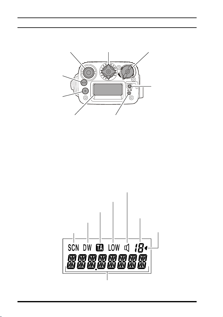
CONTROLS & CONNECTORS
Top Panel
Antenna Jack CH (Channel) Selector VOL/PWR Knob
TOP SEL2 Key
(Orange)
TOP SEL1 Key
(Gray)
Toggle Switch
LCD (Liquid Crystal Display)
Low Transmit Power Mode On
Talk-Around Mode
This Channel on
“DUAL WATCH” List
This Channel on “SCAN” List
8 Character Alpha-numeric Invertible Display
LED Indicator
Steady Green: Signaling off
Blinking Green: Busy Channel (or SQL off)
Steady Red: Transmission inProgress
Blinking Red: Battery voltage is low
LCD
Receive Monitor
Steady On: Signaling off
Blinking: Busy Channel (or SQL off)
Channel Group Number
(
“01” ~ “19” and “0”
Group Scan Enabled
(this group)
)
Page 2
Vertex Standard Co., Ltd.
VX-530 SERIES OPERATING MANUAL
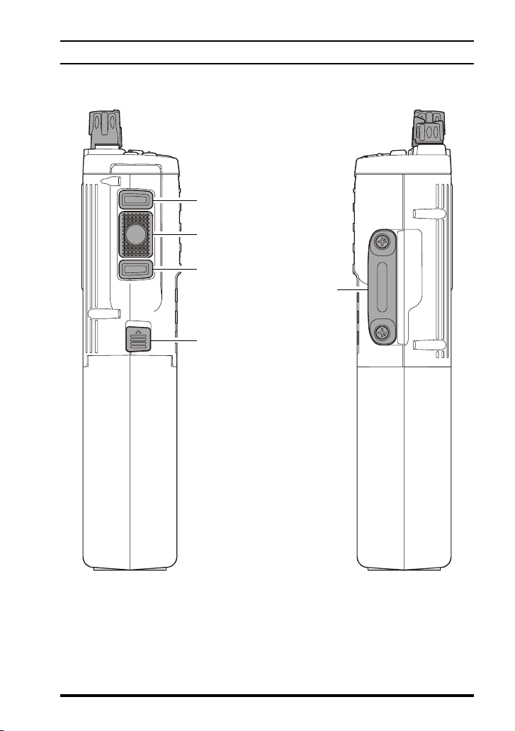
CONTROLS & CONNECTORS
Side Panels
SIDE SEL1 Key
PTT Switch
SIDE SEL2 Key
MIC/SP Jack
(External MIC/SP)
Battery Release Button
Vertex Standard Co., Ltd.
Page 3
VX-530 SERIES OPERATING MANUAL
BEFORE YOU BEGIN
Preliminaries
If the transceiver has not been used since leaving the factory, fully charge
the battery using VAC-520 Rapid Desktop Charger before using it.
Mount the battery on the transceiver as described and shown in the illustration below. Also, install the antenna on the jack on top of the transceiver by
screwing the connector into the jack until it is finger-tight.
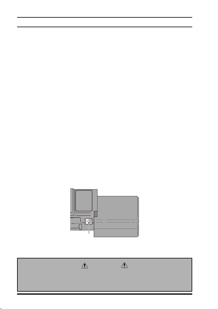
Battery Removal & Replacement
Make sure that the VOL control is set into the “off” click-stop (fully
counter-clockwise, and remove the protective soft or hard case, if used.
Grasp the transceiver with your left hand, so your palm is over the
speaker and your thumb is on the Battery Release Button.
Move the Battery Release Button in the direction indicated by the ar-
rowhead, while using your right hand to slide the battery pack toward
the side with the button. The battery pack should slide smoothly out of
its track.
To replace the Ni-Cd pack, repeat the second and third steps above,
simply sliding the battery case in the other direction after aligning the
shorter side of the battery pack with the track below the Battery Release Button.
Caution
Danger of explosion if battery is replaced with an incorrect battery.
Replace only with the same or equivalent type.
Page 4
Vertex Standard Co., Ltd.

VX-530 SERIES OPERATING MANUAL
BEFORE YOU BEGIN
Low Battery Indication
As the battery discharges during use, the voltage gradually becomes
lower. When the battery voltage falls below the operating voltage range
of the radio, it is time to substitute a freshly charged battery and recharge the depleted pack. The LED indicator on the top of the radio
will blink red when the battery voltage is low.
Avoid recharging Ni-Cd batteries often with little use between charges,
as this can degrade the charge capacity. We recommend that you carry
an extra, fully-charged pack with you so the operational battery may be
used until depletion (this “deep cycling” technique promotes better longterm battery capacity).
Vertex Standard Co., Ltd.
Page 5

VX-530 SERIES OPERATING MANUAL
BASIC OPERATION
Preliminary Steps
Install a charged battery pack onto the trans-
ceiver, as described previously.
Screw the supplied antenna onto the Antenna
jack. Never attempt to operate this transceiver
without an antenna connected.
If you have a Speaker/Microphone, we rec-
ommend that it not be connected until you
are familiar with the basic operation of the
VX-530.
Operation Quick Start
Turn the top panel’s VOL/PWR knob clock-
wise to turn on the radio.
Turn the top panel’s CH selector knob to choose the desired operating
channel. A channel name will appear on the
LCD. If you want to select the operating channel from a different Memory Channel Group,
press the Soft key assigned to the “Memory
Group Up” or “Memory Group Down” function to select the Memory Channel Group containing the desired operating channel. A group name will appear on the LCD whenever the
Soft key is pressed.
Note: Some models are programmed so that the operating channels
are selected by the Soft key and the memory channel group is selected by the CH selector knob. For further details, contact your
Vertex Standard dealer.
Page 6
Vertex Standard Co., Ltd.
 Loading...