

Yaesu VX-510 Operating Manual

VX-510
VHF Hand-Held Portable
Land Mobile Transceiver
OPERATING MANUAL
VERTEX STANDARD CO., LTD.
4-8-8 Nakameguro, Meguro-Ku, Tokyo 153-8644, Japan
VERTEX STANDARD
US Headquarters
10900 Walker Street, Cypress, CA 90630, U.S.A.
YAESU UK LTD.
Unit 12, Sun Valley Business Park, Winnall Close
Winchester, Hampshire, SO23 0LB, U.K.
VERTEX STANDARD HK LTD.
Unit 5, 20/F., Seaview Centre, 139-141 Hoi Bun Road,
Kwun Tong, Kowloon, Hong Kong
VERTEX STANDARD (AUSTRALIA) PTY., LTD.
Normanby Business Park, Unit 14/45 Normanby Road
Notting Hill 3168, Victoria, Australia

Congratulations!
You now have at your fingertips a valuable communications tool - a
yaesu two-way radio! Rugged, reliable and easy to use, your yaesu
radio will keep you in constant touch with your colleagues for years to
come, with negligible maintenance down time.
Please take a few minutes to read this manual carefully. The information presented here will allow you to derive maximum performance
from your radio. After reading it, keep the manual handy for quick
reference, in case questions arise later on.
We’re glad you joined the yaesu team. Call on us any time, because
our business is communications. Let us help you get your message
across.
NOTICE
There are no user-serviceable points inside this transceiver. All
service jobs must be referred to your Authorized Service Center or Network Administrator.
VX-510 OPERATING MANUAL
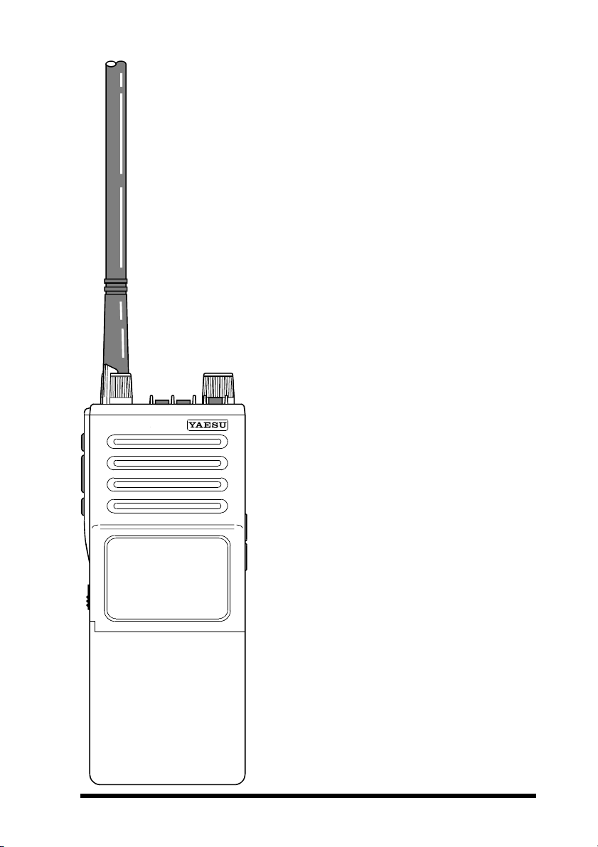
VX-510 Series
VHF Hand-Held Portable
Land Mobile Transceiver
The VX-510 is a frequency-synthesized, microprocessor-controlled FM hand-held portable transceiver providing up to five watts
of power output on up to 32 channels in the
VHF Land Mobile Bands. Designed specifically for commercial and professional applications, the VX-510 is housed in highstrength die-cast aluminum alloy, sealed to
MIL-810 C, D & E intrinsically safe (I/S)
and weather-tight specifications.
User selectable features include a four-mode
display with channel name or number, upright or inverted for easy viewing when on
your belt; selective channel scanning, adjustable-pause priority scanning, and variable transmitter power output.
Other user-selectable features include pushbutton display illumination, voice encryption for privacy during communications
(with optional FVP-22 Unit installed), and
manual squelch override. The VX-510 is
easily programmed by your dealer using a
Yaesu Service Kit with an IBM PC-compatible computer.
Please read this manual carefully to become
familiar with the features of the VX-510.
1

VX-510 OPERATING MANUAL
SPECIFICATIONS
General
Frequency range (MHz): 29.8 – 38 MHz (vers.A) or 38 – 50 MHz (vers.B)
Channels: Up to 32 (simplex or semi-duplex)
Maximum Channel Spread: 8.3 MHz (vers. A) or 12 MHz (vers. B)
Minimum Channel Spacing: 20 kHz (12.5 kHz optional)
Programming Channel Step: 5/6.25 kHz
Emission Type: 16K0F3E (11K0F3E optional)
Supply Voltage: 7.2 V DC 10%
Current Consumption: 50 mA (stby, saver off)
Case Size (W x H x D): 59 x 149 x 39mm
Weight (approx.): 570 grams
Receiver
Receiver Circuit Type: Double-conversion Superheterodyne
Intermediate Frequencies: 21.6 MHz (ver. A), 16.9 MHz (vers.B) &
12-dB SINAD Sensitivity: better than 0.20µV
20-dB Noise Quieting: better than 0.30µV
Squelch Threshould: better than 0.18µV
Adjacent Channel Selectivity: 75 dB
Image Rejection: 80 dB
Intermodulation Response: 70 dB
Hum & Noise: 50 dB
Audio Response: +3/−8 dB from the 6 dB/oct. De-emphasis curve
AF output (for 5% THD): 0.5 watts @16 Ω
19 mA (stby, saver on)
200 mA (receive)
2000 mA (transmit)
455 kHz
Transmitter
Power Output: 5W/1W
Frequency Stability: ±10 ppm
Modulation System: variable reactance
Maximum Deviation: ±5 kHz (±2.5 kHz optional)
Audio Response: TIA/EIA-603 3.2.6
FM Hum and Noise: better than −50 dB
Spurious Emissions: 60 dB below carrier
AF Distortion (@ 1 kHz): < 5% @60 % modulation
Microphone Type: 2-k Ω condenser
Specifications may be subject to change without notice or obligation.
2

VX-510 OPERATING MANUAL
ACCESSORIES & OPTIONS
MH- 30
MH- 45
FNB-29A 7.2 V/1700 mAh Ni-Cd Battery Pack
VAC-520 Rapid Desktop Charger
ATL-1A VHF Low Band Helical Flex Antenna (30 – 36 MHz)
ATL-1B VHF Low Band Helical Flex Antenna (36 – 42 MHz)
ATL-1C VHF Low Band Helical Flex Antenna (42 – 50 MHz)
FVP-22 Encryption Unit
FTT-7 DTMF Keypad Tone Generator (16 keys)
FTT-7D DTMF Keypad Tone Generator w/Decoder
FTE-19 ANI (Auto Numbering Identification) Unit
CE-21 Programming Software
VPL-1 Programming Cable
VTP-20 VX-Trunk II VX-Trunking Portable Logic Board
CLIP-4A Belt Clip
A2B
A2B
Speaker/Microphone
Speaker/Microphone
3
VX-510 OPERATING MANUAL
CONTROLS & CONNECTORS
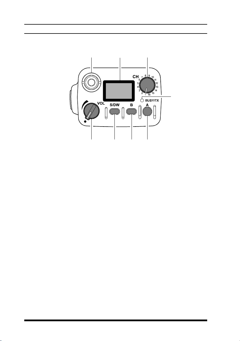
Top panel
VOL Control
This control adjusts the volume of the receiver, and turns the radio off
when rotated fully counterclockwise to the click-stop
S/DW Button (Scan/Dual Watch)
Momentarily (< 1sec.) pressing this button turns the channel scanner on
and off. Pressing and holding (> 1 sec.) this button activates the Dual
Watch feature (explained later).
B Button
Pressing and holding this button more than 2 seconds (but less than 4
seconds) activates functions as programmed by your dealer and determined
by your system requirements (See “P
13). Pressing and holding this button more than 4 seconds inverts the
LCD display to either frontward or backward facing readout (the backward display is convenient for viewing when wearing the transceiver on
your belt).
RE-PROGRAMMED FUNCTIONS”, page
4
VX-510 OPERATING MANUAL
CONTROLS & CONNECTORS
A Button
Pressing and holding this button more than 2 seconds (but less than 4
seconds) also activates an assigned function (programmed by your dealer).
Pressing and holding this button more than 4 seconds causes the selected
channel to be assigned as the Priority Channel for use with Priority Scanning and Dual Watch functions (explained later).
BUSY/TX Indicator
This lamp blinks green when a signal is being received (or the squelch is
opened by pressing the MON RES button) and red when transmitting. To
avoid interference, do not transmit if the lamp is glowing green. When the
battery almost depleted, this lamp blinks red, indicating that the battery
needs recharging or replacement very soon.
CH Rotary Selector
This rotary switch selects the operating channel. If a channel is selected
that is not available for operation, “
nied by a rapid warning beeper (2 beeps/sec.).
-- -- -- --
” is displayed, accompa-
Antenna Jack
This threaded-type jack accepts the supplied flexible antenna. Any other
antenna types used here must be designed for the programmed operating
frequencies.
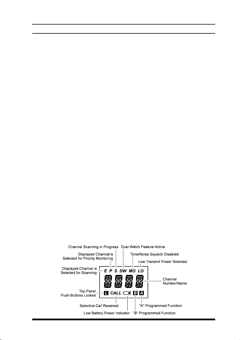
Liquid Crystal Display
In addition the channel number name, the display includes some operating
status symbols, indicated in the diagram below.
5
VX-510 OPERATING MANUAL
CONTROLS & CONNECTORS
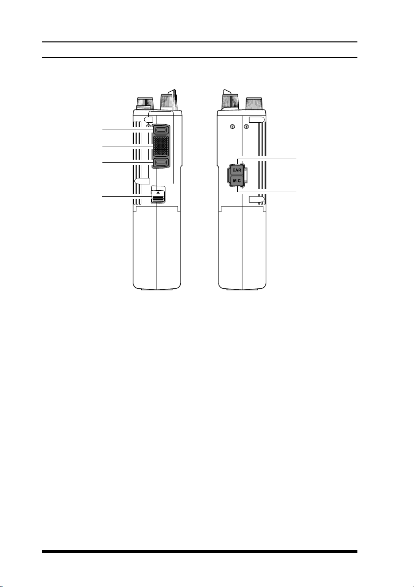
Side Panel Buttons
MON RES (Monitor/Reset) Button
Pressing and holding this button more than 2 seconds (but less than 4
seconds) disables the tone squelch, and permits monitoring of stations
transmitting on the selected channel while still keeping your receiver quiet
from noise (“MO ” will appear at the top right of the LCD). Press it again
to only hear calls within your network.
Pressing and holding this button more than 4 seconds toggles the tone and
noise squelch override, allowing all stations (and noise) on the channel to
be heard. This may be used to hear weak stations whose signals would not
normally open the squelch. Do this to pre-adjust the VOLume control
before receiving calls.
(With Selective Calling Option)
When the two-tone sequential decoder unit (F2D-5) is installed, and a
selective call has been received (“CALL” indicator on), pressing and
holding this button more than 2 seconds (but less than 4 seconds) will
reset the call function on the current channel and silence the receiver,
otherwise pressing and holding this button more than 4 seconds resets the
call function on ALL channels.
6
 Loading...