

Page 1
INSTRUCTION MANUAL
e-1531
e-1532
P2001409 Rev D
Series e-1531 and
e-1532
Page 2

Page 3

Table of Contents
1 Introduction and Safety..............................................................................................................3
1.1 Introduction.......................................................................................................................... 3
1.2 Safety..................................................................................................................................... 3
1.2.1 Safety terminology and symbols.................................................................................3
1.2.2 Safety instruction decals.............................................................................................. 4
1.2.3 User safety......................................................................................................................5
1.2.4 Protecting the environment.........................................................................................6
2 Transportation and Storage...................................................................................................... 7
2.1 Examine the delivery........................................................................................................... 7
2.1.1 Examine the package................................................................................................... 7
2.1.2 Examine the unit............................................................................................................7
2.2 Safe handling requirements............................................................................................... 7
2.3 Long-term storage............................................................................................................... 8
3 Product Description................................................................................................................. 10
3.1 General description...........................................................................................................10
3.2 Operational specifications................................................................................................10
Table of Contents
4 Installation................................................................................................................................. 12
4.1 Preinstallation.....................................................................................................................12
4.1.1 Pump location guidelines..........................................................................................12
4.1.2 Foundation requirements..........................................................................................13
4.1.3 Piping checklist........................................................................................................... 14
4.1.4 Typical installation...................................................................................................... 15
4.1.5 Special installation......................................................................................................15
4.2 Install the pump with motor (e-1532)..............................................................................16
4.3 Level the base on a concrete foundation for pumps with base (e-1532)................... 16
4.4 Grout the baseplate (e-1532)...........................................................................................16
4.5 Install the piping................................................................................................................ 17
5 Commissioning, Startup, Operation, and Shutdown.......................................................... 18
5.1 Preparation for startup...................................................................................................... 18
5.2 Prime the pump................................................................................................................. 18
5.3 Start the pump....................................................................................................................19
5.4 Pump operation precautions............................................................................................19
5.5 Shut down the pump.........................................................................................................20
5.6 Note on the packed pump operation............................................................................. 20
6 Maintenance..............................................................................................................................21
6.1 Bearing maintenance........................................................................................................ 21
6.2 Disassembly........................................................................................................................21
6.2.1 Disassembly precautions...........................................................................................21
6.2.2 Drain the pump...........................................................................................................21
6.2.3 Remove the rotating assembly and motor.............................................................. 21
6.2.4 Remove the mechanical seal (e-1531/e-1532 and e-1531/e-1532-F)................. 22
6.2.5 Remove the seal or packing rings (e-1531/e-1532-S, e-1531/e-1532-D, and
e-1531/e-1532-PF)...........................................................................................................22
6.2.6 Impeller trimming guidelines....................................................................................22
6.3 Pre-assembly inspections................................................................................................. 23
Series e-1531 and e-1532 INSTRUCTION MANUAL 1
Page 4

Table of Contents
6.3.1 Shaft and sleeve inspection.......................................................................................23
6.4 Reassembly.........................................................................................................................24
6.4.1 Seal assembly..............................................................................................................24
6.4.2 Assemble the packed stuffing box (e-1531/e-1532-PF)........................................26
6.4.3 Reinstall the rotating assembly and motor..............................................................26
6.4.4 Capscrew torque values............................................................................................ 27
6.4.5 Dealer servicing ......................................................................................................... 27
7 Product warranty...................................................................................................................... 28
2 Series e-1531 and e-1532 INSTRUCTION MANUAL
Page 5
1 Introduction and Safety
1.1 Introduction
Purpose of this manual
The purpose of this manual is to provide necessary information for:
• Installation
• Operation
• Maintenance
CAUTION:
Read this manual carefully before installing and using the product. Improper use of the
product can cause personal injury and damage to property, and may void the warranty.
NOTICE:
Save this manual for future reference, and keep it readily available at the location of the
unit.
1 Introduction and Safety
1.2 Safety
WARNING:
• The operator must be aware of safety precautions to prevent physical injury.
• Operating, installing, or maintaining the unit in any way that is not covered in this
manual could cause death, serious personal injury, or damage to the equipment. This
includes any modification to the equipment or use of parts not provided by Xylem. If
there is a question regarding the intended use of the equipment, please contact a
Xylem representative before proceeding.
• Do not change the service application without the approval of an authorized Xylem
representative.
CAUTION:
You must observe the instructions contained in this manual. Failure to do so could result
in physical injury, damage, or delays.
1.2.1 Safety terminology and symbols
About safety messages
It is extremely important that you read, understand, and follow the safety messages and
regulations carefully before handling the product. They are published to help prevent
these hazards:
• Personal accidents and health problems
• Damage to the product and its surroundings
• Product malfunction
Hazard levels
Hazard level Indication
Series e-1531 and e-1532 INSTRUCTION MANUAL 3
DANGER:
A hazardous situation which, if not avoided, will result in
death or serious injury
Page 6
1 Introduction and Safety
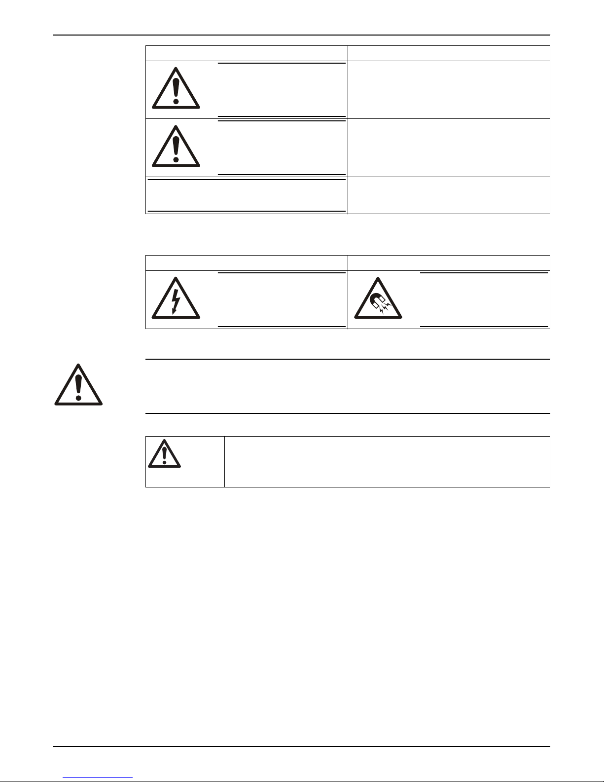
Hazard level Indication
WARNING:
A hazardous situation which, if not avoided, could result
in death or serious injury
NOTICE:
Special symbols
Some hazard categories have specific symbols, as shown in the following table.
Electrical hazard Magnetic fields hazard
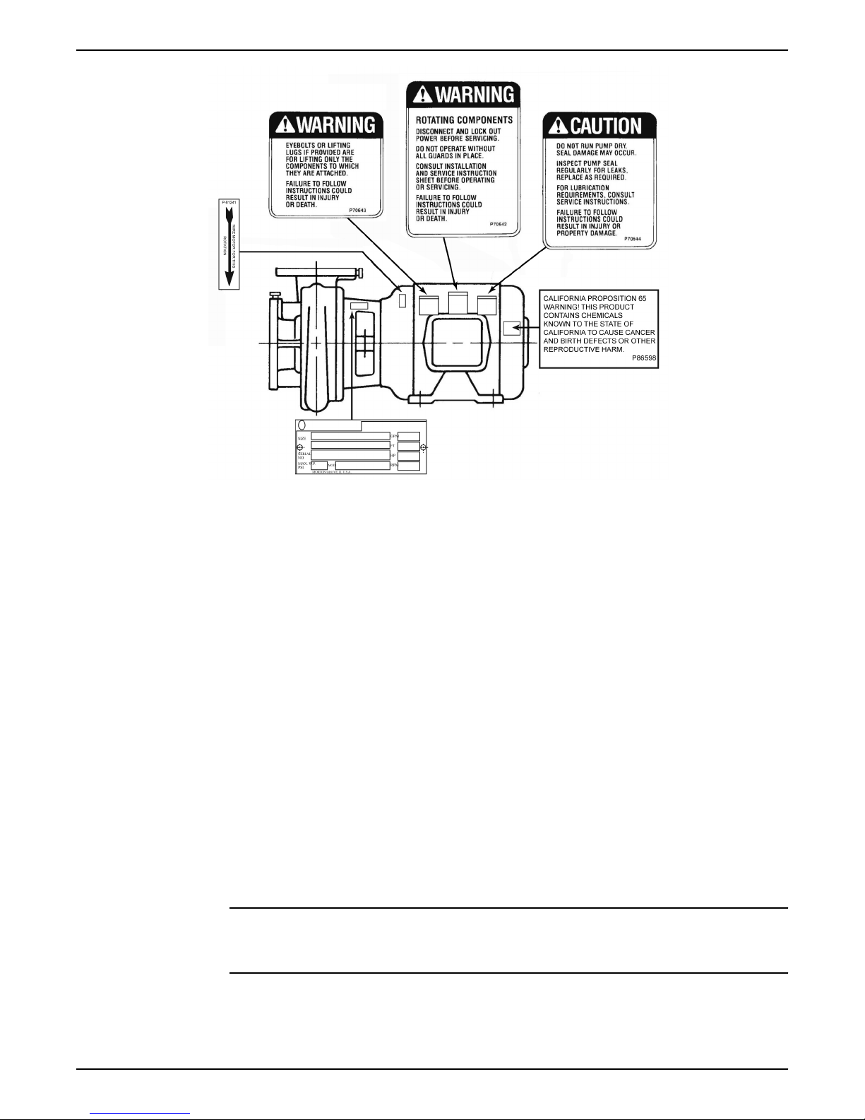
1.2.2 Safety instruction decals
WARNING:
Do NOT exceed the maximum working pressure of the pump. This information is listed on
the nameplate of the pump.
CAUTION:
Electrical Hazard:
A hazardous situation which, if not avoided, could result
in minor or moderate injury
Notices are used when there is a risk of equipment
damage or decreased performance, but not personal
injury.
CAUTION:
Alert symbol
Decals
This safety alert symbol is used in manuals and on the safety instruction decals on the pump
to draw attention to safety-related instructions.
When used, the safety alert symbol means that failure to follow the instructions may result in
a safety hazard.
Make sure your pump has these safety instruction decals and that they are located as this
figure shows. If the decals are missing or illegible, contact your local sales and service
representative for a replacement.
4 Series e-1531 and e-1532 INSTRUCTION MANUAL
Page 7
1 Introduction and Safety
1.2.3 User safety
General safety rules
Safety equipment
Make sure that all safety instruction decals are always clearly visible and readable.
These safety rules apply:
• Always keep the work area clean.
• Pay attention to the risks presented by gas and vapors in the work area.
• Avoid all electrical dangers. Pay attention to the risks of electric shock or arc flash
hazards.
• Always bear in mind the risk of drowning, electrical accidents, and burn injuries.
Use safety equipment according to the company regulations. Use this safety equipment
within the work area:
• Hard hat
• Safety goggles, preferably with side shields
• Protective shoes
• Protective gloves
• Gas mask
• Hearing protection
• First-aid kit
• Safety devices
NOTICE:
Never operate a unit unless safety devices are installed. Also see specific information
about safety devices in other chapters of this manual.
Electrical connections
Electrical connections must be made by certified electricians in compliance with all
international, national, state, and local regulations. For more information about
requirements, see sections dealing specifically with electrical connections.
Series e-1531 and e-1532 INSTRUCTION MANUAL 5
Page 8

1 Introduction and Safety
Precautions before work
Observe these safety precautions before you work with the product or are in connection
with the product:
• Provide a suitable barrier around the work area, for example, a guard rail.
• Make sure that all safety guards are in place and secure.
• Make sure that you have a clear path of retreat.
• Make sure that the product cannot roll or fall over and injure people or damage
property.
• Make sure that the lifting equipment is in good condition.
• Use a lifting harness, a safety line, and a breathing device as required.
• Allow all system and pump components to cool before you handle them.
• Make sure that the product has been thoroughly cleaned.
• Disconnect and lock out power before you service the pump.
• Check the explosion risk before you weld or use electric hand tools.
1.2.3.1 Wash the skin and eyes
Follow these procedures for chemicals or hazardous fluids that have come into contact
with your eyes or your skin:
Condition Action
Chemicals or hazardous fluids in
eyes
Chemicals or hazardous fluids on
skin
1. Hold your eyelids apart forcibly with your fingers.
2. Rinse the eyes with eyewash or running water for at least 15 minutes.
3. Seek medical attention.
1. Remove contaminated clothing.
2. Wash the skin with soap and water for at least 1 minute.
3. Seek medical attention, if necessary.
1.2.4 Protecting the environment
Emissions and waste disposal
Observe the local regulations and codes regarding:
• Reporting of emissions to the appropriate authorities
• Sorting, recycling and disposal of solid or liquid waste
• Clean-up of spills
Exceptional sites
CAUTION: Radiation Hazard
Do NOT send the product to Xylem if it has been exposed to nuclear radiation, unless
Xylem has been informed and appropriate actions have been agreed upon.
Recycling guidelines
Always follow local laws and regulations regarding recycling.
6 Series e-1531 and e-1532 INSTRUCTION MANUAL
Page 9

2 Transportation and Storage
2 Transportation and Storage
2.1 Examine the delivery
2.1.1 Examine the package
1. Examine the package for damaged or missing items upon delivery.
2. Record any damaged or missing items on the receipt and freight bill.
3. If anything is out of order, then file a claim with the shipping company.
If the product has been picked up at a distributor, make a claim directly to the
distributor.
2.1.2 Examine the unit
1. Remove packing materials from the product.
Dispose of all packing materials in accordance with local regulations.
2. To determine whether any parts have been damaged or are missing, examine the
product.
3. If applicable, unfasten the product by removing any screws, bolts, or straps.
Use care around nails and straps.
4. If there is any issue, then contact a sales representative.
2.2 Safe handling requirements
WARNING:
• Personal protective equipment should be worn when handling this equipment.
• Transportation & installation of this equipment should only be performed by qualified
personnel.
• A professional rigging company should be consulted before lifting the pump
assembly.
• Only use properly sized, certified lifting equipment & lifting devices, including slings,
suitably rated for the weights to be lifted.
• Slings, when used, must be of identical materials to avoid differences in stretch rates.
• Do not use lifting devices that are frayed, kinked, unmarked, or worn.
• Lifting eyebolts fitted on single components of the assembly (pump or motor) must not
be used to lift the complete assembly.
• Failure to observe these instructions could result in equipment or property damage,
serious injury, or death.
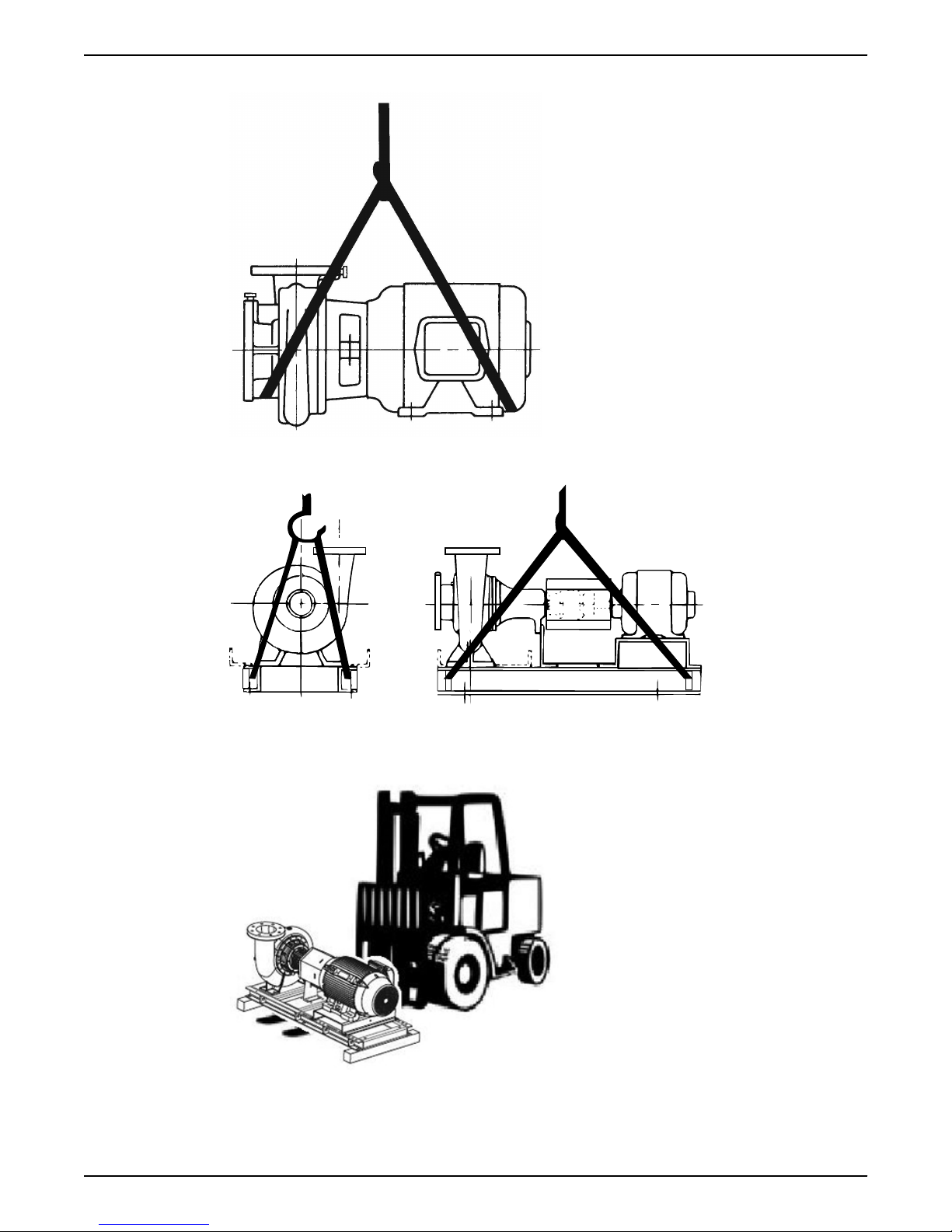
The pump assembly can arrive in as a pump without base, or a base-mounted pump
(e-1532 only). Use the following recommended ways of handling e-1531 or e-1532 pump
assemblies. The pump assembly should remain horizontal during transport and lifting.
Table 1: Lifting methods
Pump type Lifting method
A pump without base. Use a suitable sling attached properly to solid points under the casing and motor.
A base-mounted pump.
(e-1532 only)
Lifting the pump less motor or the pump, motor, & baseplate should be done by
using lifting lugs provided on the baseplate, or by utilizing a forklift under the
entire unit. Always take extra precaution to ensure the weight is balanced & equally
distributed across both forks. When the baseplate of the assembly is structural
channel construction, the pump and base plate should be set in place first. The
motor should then be separately lifted & mounted to the unit.
Series e-1531 and e-1532 INSTRUCTION MANUAL 7
Page 10
2 Transportation and Storage
Examples
Figure 1: Example of a proper lifting method for pump without base
Figure 2: Example of a proper lifting method using lifting lugs for base mounted pump (e-1532
only)
Figure 3: Lift using a forklift
2.3 Long-term storage
8 Series e-1531 and e-1532 INSTRUCTION MANUAL
Page 11

2 Transportation and Storage
If the unit is stored for more than 6 months, these requirements apply:
• Store in a covered and dry location.
• Store the unit free from heat, dirt, and vibrations.
• Rotate the shaft by hand several times at least every three months.
Treat bearing and machined surfaces so that they are well preserved. Refer to the drive
unit manufacturer for their long-term storage procedures.
For questions about possible long-term storage treatment services, please contact your
local sales and service representative.
Series e-1531 and e-1532 INSTRUCTION MANUAL 9
Page 12

3 Product Description
3 Product Description
3.1 General description
Description
The pump is a centrifugal, close-coupled pump. The following pump features make it easy
to install, operate, and service:
• High efficiency
• Rugged stainless steel-fitted construction
• Footless (e-1531) or Foot-mounted (e-1532) volute
Intended applications
WARNING:
This product can expose you to chemicals including Lead, which is known to the State of
California to cause cancer and birth defects or other reproductive harm. For more
information go to: www.P65Warnings.ca.gov.
The pump is intended for use with these pumped
• Unheated domestic and fresh water
• Boiler feed water
• Condensate
• Hydronic cooling or heating
• Benign liquids
• Pressure boosting
• General liquid transfer
Rotation
Pump rotation is clockwise when viewed from the back of the motor. An arrow is also
located on the pump to show the direction of rotation.
3.2 Operational specifications
Mechanical seal specifications
Seal type/
Parameter
Operating
temperature
range, °F (°C)
pH range limits 7.0 to 9.0 7.0 to 11.0 7.0 to 9.0 7.0 to 12.5 7.0 to 9.0 7.0 to 9.0
Resistance to
dissolved
solids
Maximum
glycol/water
concentration
Standard seal,
BUNA/Carbon/
Ceramic
-20 to 225 (-29
to 107)
Low Low-Medium Low Medium-High Low-Medium Medium
50/50% 50/50% 50/50% 60/40% 50/50% Not
Optional seal,
EPR/Carbon /
Tungsten
Carbide
-20 to 250 (-29
to 121)
Optional seal,
FKM/Carbon /
Ceramic
-10 to 225 (-23
to 107)
fluids:
Optional seal,
EPR/Silicon
Carbide/Silicon
Carbide
-20 to 250 (-29
to 121)
Optional seal,
EPR/Carbon /
Tungsten
Carbide with
external
1,3,4
flush
-20 to 250 (-29
to 121)
2
Packing
0 to 200 (-18
to 93)
recommended
Table notes
10 Series e-1531 and e-1532 INSTRUCTION MANUAL
Page 13

3 Product Description
1. An external flush is required on low pressure systems that contain a high concentration
of abrasives.
2. Use packing on open or closed systems which require a large amount of makeup
water, as well as systems that are subjected to a wide variety of chemical conditions
and solids buildup.
3. For operating temperatures above 250°F, a cooled flush is required and is
recommended for temperatures above 225°F for optimum seal life. On closed
systems, cooling is accomplished by inserting a small heat exchanger in the flush line
to cool the seal flushing fluid.
4. Flush-line filters and sediment separators are available on request.
Series e-1531 and e-1532 INSTRUCTION MANUAL 11
Page 14

4 Installation
4 Installation
4.1 Preinstallation
Precautions
WARNING:
• When installing in a potentially explosive environment, make sure that the motor is
properly certified.
• You must ground (earth) all electrical equipment. This applies to the pump equipment,
the driver, and any monitoring equipment. Test the ground (earth) lead to verify that it
is connected correctly.
NOTICE:
Supervision by an authorized Xylem representative is recommended to ensure proper
installation. Failure to do so may result in equipment damage or decreased performance.
Evaluate the installation in order to determine that the Net Positive Suction Head Available
(NPSHA) meets or exceeds the Net Positive Suction Head Required (NPSHR), as stated by
the pump performance curve.
4.1.1 Pump location guidelines
WARNING:
Assembled units and their components are heavy. Failure to properly lift and support this
equipment can result in serious physical injury and/or equipment damage. Lift equipment
only at the specifically identified lifting points. Lifting devices such as eyebolts, slings, and
spreaders must be rated, selected, and used for the entire load being lifted.
Guideline Explanation/comment
Keep the pump as close to the liquid source as
practically possible.
Make sure that the space around the pump is
sufficient.
If you require lifting equipment such as a hoist or
tackle, make sure that there is enough space above
the pump.
Protect the unit from weather and water damage due
to rain, flooding, and freezing temperatures.
Do not install and operate the equipment in closed
systems unless the system is constructed with
properly-sized safety devices and control devices.
Take into consideration the occurrence of unwanted
noise and vibration.
If the pump location is overhead, undertake special
precautions to reduce possible noise transmission.
When possible, locate the pump below the fluid
level.
This minimizes the friction loss and keeps the suction piping
as short as possible.
This facilitates ventilation, inspection, maintenance, and
service.
This makes it easier to properly use the lifting equipment and
safely remove and relocate the components to a safe location.
This is applicable if nothing else is specified.
Acceptable devices:
• Pressure relief valves
• Compression tanks
• Pressure controls
• Temperature controls
• Flow controls
If the system does not include these devices, consult the
engineer or architect in charge before you operate the pump.
The best pump location for noise and vibration absorption is
on a concrete floor with subsoil underneath.
Consider a consultation with a noise specialist.
This facilitates priming, ensures a steady flow of liquid, and
provides a positive suction head on the pump.
12 Series e-1531 and e-1532 INSTRUCTION MANUAL
Page 15

4.1.2 Foundation requirements
Correct
Incorrect
2
3
1
4
Requirements
• The foundation must be able to absorb any type of vibration and form a permanent,
rigid support for the unit.
• The foundation must weigh at least 2-1/2 times the weight of the pump unit.
• Provide a flat, substantial concrete foundation in order to prevent strain and distortion
when you tighten the foundation bolts. Tie the concrete pad in with the finished floor.
Bolt installation — pump to concrete
• Use some type of expansion fitting in order to facilitate easy servicing. Insert the
female portion into a suitable hole in the pad so that its top surface is flush with the
pad surface. Thus, when the hold-down bolts are removed, the motor can be removed
by sliding it back from the pump.
•
4 Installation
Bolt installation with baseplate (e-1532)
• Sleeve-type and J-type foundation bolts are most commonly used. Both designs allow
movement for the final bolt adjustment.
• Use foundation bolts and larger pipe sleeves to give room for final bolt location.
1. Foundation bolt
2. Pipe sleeve
3. Washer
4. Built-up concrete foundation
Series e-1531 and e-1532 INSTRUCTION MANUAL 13
Page 16

4 Installation
4.1.3 Piping checklist
WARNING:
• The heating of water and other fluids causes volumetric expansion. The associated
forces can cause the failure of system components and the release of hightemperature fluids. In order to prevent this, install properly sized and located
compression tanks and pressure-relief valves. Failure to follow these instructions can
result in serious personal injury or death, or property damage.
• Avoid serious personal injury and property damage. Make sure that the flange bolts
are adequately torqued.
NOTICE:
Never force piping to make a connection with a pump.
Check Explanation/comment Checked
Check that a section of straight pipe, with a length that
is five times its diameter, is installed between the
suction side of the pump and the first elbow, or that a
B&G Suction Diffuser is installed.
Check that the suction and discharge pipes are
supported independently by use of pipe hangers near
the pump .
Check that there is a strong, rigid support for the
suction and discharge lines.
For pumps with flanges, check that the bolt holes in
the pump flanges match the bolt holes in the pipe
flanges.
Check that the suction or discharge lines are not
forced into position.
Check that fittings for absorbing expansion are
installed in the system when considerable
temperature changes are expected.
Check that you have a foot valve of equal or greater
area than the pump suction piping when you use in
an open system with a suction lift.
Check that flexible piping is used on both the suction
and discharge sides of the pump when you use an
isolation base.
Check that a B&G Triple Duty® valve is installed in the
discharge line.
Check that the pipeline has isolation valves around
the pump and has a drain valve in the suction pipe.
Use PTFE tape sealer or a high quality thread sealant
when you install the suction and discharge
connections to a threaded pump housing.
This reduces suction turbulence by
straightening the flow of liquid before it enters
the pump.
This eliminates pipe strain on the pump .
As a rule, ordinary wire or band hangers are not
adequate to maintain proper alignment.
—
Coupling and bearing wear will result if suction
or discharge lines are forced into position.
This helps to avoid strain on the pump.
Prevent clogging by using a strainer at the
suction inlet next to the foot valve. Make sure
that the strainer has an area three times that of
the suction pipe with a mesh hole diameter of
no less than 0.25 in. (0.64 cm).
—
This valve serves as a check valve that protects
the pump from water hammer, and serves as an
isolation valve for servicing and for throttling.
—
—
14 Series e-1531 and e-1532 INSTRUCTION MANUAL
Page 17

4.1.4 Typical installation
3
4
5
6
7
8
2
9
10
11
1
12
13
14
4 Installation
1. Expansion tank
2. B&G Rolairtrol® air separator
3. Supply to system
4. TPV Tank Purge Valve
5. B&G Triple Duty® valve
6. B&G Series e-1531 or e-1532 Pump
7. B&G Suction Diffuser
8. Isolation valve
9. Pipe from boiler, chiller, or converter
10.Cold water supply
11.B&G Pressure Reducing Valve
12.B&G Model 107A — High capacity vent
13.B&G #7 or #87 Air Vent
14.Drain valve
4.1.5 Special installation
Installation with suction diffuser and triple-duty valve
Installation with isolation base
Do not install and operate triple-duty valves and suction diffusers in closed systems unless
the system is designed with these safety and control devices:
• Pressure relief valves
• Compression tanks
• Pressure controlling equipment
• Temperature controlling equipment
• Flow controlling equipment
Check that the control and safety devices have these characteristics:
• Properly sized for their purpose
• Placed correctly in the system before putting the system into operation
When using an isolation base, flexible piping should be used on both suction and
discharge sides to reduce the strain on the flanges.
Series e-1531 and e-1532 INSTRUCTION MANUAL 15
Page 18

4
1
5
2
3
6
7
8
4 Installation
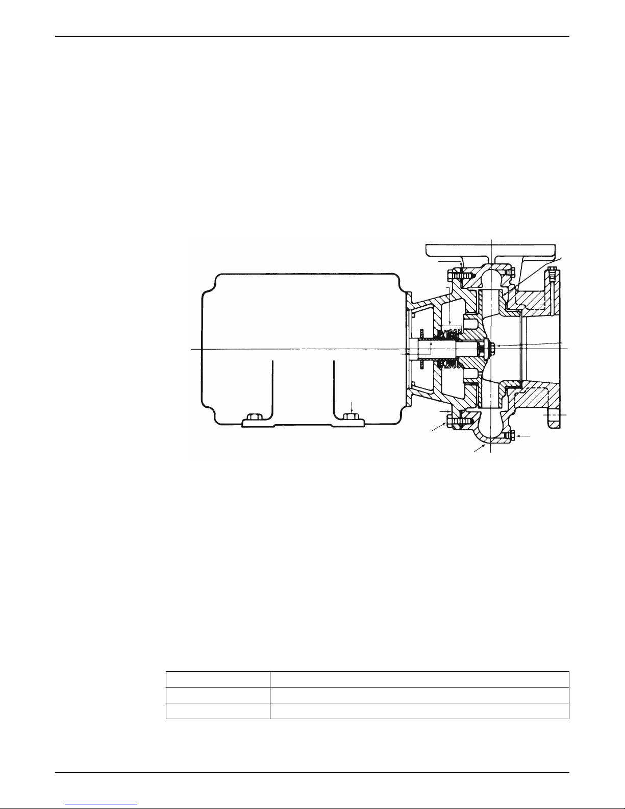
4.2 Install the pump with motor (e-1532)
1. Place the pump with motor where it will be mounted, on the floor, on a raised concrete
pad or on a base, with two 0.060 in (1.5 mm) thick shims provided under each of the
four hold down bolt locations of the pump volute feet. With certain tall motors and
short pumps, one or two additional 1” (25.4 mm) thick steel shims will be provided to
go under the pump casing feet to make the volute level with the bottom of the motor
support or motor feet.
2. Then add additional shims at each of the four volute hold down bolt locations, as
required, until the volute feet are fully supported, the pump discharge flange is level,
and there is a gap under the motor saddle or motor feet. Tighten the four bolts at the
volute feet.
3. Loosen the bolts between the motor and the motor saddle, when a saddle is used, and
fill any gaps to fully support the motor by adding shims under the motor feet at each of
the motor’s four hold down bolt locations, as required, until all four hold down hole
locations of the motor saddle or motor feet contact the floor, pad, or base. Tighten the
bolting between the motor and motor saddle, when a saddle is used.
4. When mounted on a baseplate, then tighten the four hold down bolts at the corners of
the motor support or motor feet. For pumps mounted directly on the floor or concrete
pad, all four motor saddle or motor hold down bolt locations must be in contact with
the floor or pad, but hold down bolting at these locations is optional.
5. If any hold down bolt tightening results in pump movement that could induce stress in
the pump frame, stop and re-shim the pump volute, motor saddle or motor.
4.3 Level the base on a concrete foundation for pumps with base
(e-1532)
1. Place the pump on its concrete foundation.
2. Place 1.00 in./(25.40 mm) thick steel shims or wedges on both sides of each anchor
bolt in order to support the pump .
This also provides a means of leveling the base.
1. Pump Base Rail
2. Grout only to top of base rail
3. Locate the shims to allow removal after grouting.
4. Grout
5. Concrete foundation
6. Shims
7. 1” (25.40 mm) Gap
8. Allow 1” for shims. Place on both sides of anchor bolts.
4.4 Grout the baseplate (e-1532)
Required equipment:
• Cleaners: Do not use an oil-based cleaner because the grout will not bond to it. See
the instructions provided by the grout manufacturer.
• Grout: Non-shrink grout is required.
16 Series e-1531 and e-1532 INSTRUCTION MANUAL
Page 19

1. Clean all the areas of the baseplate that will come into contact with the grout.
2. Build a dam around the foundation.
3. Thoroughly wet the foundation that will come into contact with the grout.
4. Pour grout into the baseplate up to top of the base rails.
Locate shims to allow removal after grouting.
When you pour the grout, remove air bubbles from it by using one of these methods:
– Puddle with a vibrator.
– Pump the grout into place.
5. Allow the grout to set. It is recommended to remove shims, retighten anchor bolts, and
fill shim gaps with grout.
4.5 Install the piping
Connect piping to pump without pipe strain on the pump.
4 Installation
Series e-1531 and e-1532 INSTRUCTION MANUAL 17
Page 20

5 Commissioning, Startup, Operation, and Shutdown
5 Commissioning, Startup,
Operation, and Shutdown
5.1 Preparation for startup
WARNING:
• Failure to follow these precautions before you start the unit will lead to serious
personal injury and equipment failure.
• Do not operate the pump below the minimum rated flows or with the suction or
discharge valves closed. These conditions can create an explosive hazard due to
vaporization of pumped fluid and can quickly lead to pump failure and physical injury.
• If the pump, motor, or piping operate at extremely high or low temperatures, then
guarding or insulation is required. Failure to follow these instructions can result in
serious personal injury or death, and property damage.
• Always disconnect and lock out power to the driver before you perform any installation
or maintenance tasks. Failure to disconnect and lock out driver power will result in
serious physical injury.
• Operating the pump in reverse rotation can result in the contact of metal parts, heat
generation, and breach of containment.
NOTICE:
• Verify the driver settings before you start any pump.
• Make sure that the warm-up rate does not exceed 2.5°F (1.4°C) per minute.
You must follow these precautions before you start the pump:
• Flush and clear the system thoroughly to remove dirt or debris in the pipe system in
order to prevent premature failure at initial startup.
• Bring variable-speed drivers to the rated speed as quickly as possible.
• If temperatures of the pumped fluid will exceed 200°F (93°C), then warm up the pump
prior to operation. Circulate a small amount of fluid through the pump until the casing
temperature is within 100°F (38°C) of the fluid temperature.
At initial startup, do not adjust the variable-speed drivers or check for speed governor or
over-speed trip settings while the variable-speed driver is coupled to the pump. If the
settings have not been verified, then uncouple the unit and refer to instructions supplied
by the driver manufacturer.
5.2 Prime the pump
CAUTION:
Do not run the pump dry.
Make sure that the pump body is full of liquid before startup. If the system does not
automatically fill the pump body with liquid, then you must manually prime the pump.
1. Loosen the vent plugs on the pump body.
2. While venting the air from the pump body, rotate the pump shaft a few times by hand.
3. After all air has been purged from the pump, close the vent plugs.
18 Series e-1531 and e-1532 INSTRUCTION MANUAL
Page 21

5.3 Start the pump
CAUTION:
• Observe the pump for vibration levels, bearing temperature, and excessive noise. If
normal levels are exceeded, shut down the pump and resolve the issue.
Before you start the pump, you must perform these tasks:
• Open the suction valve.
• Open any recirculation or cooling lines.
1. Fully close or partially open the discharge valve, depending on system conditions.
2. Start the driver.
3. Slowly open the discharge valve until the pump reaches the desired flow.
4. Immediately check the pressure gauge to ensure that the pump quickly reaches the
correct discharge pressure.
5. If the pump fails to reach the correct pressure, perform these steps:
a) Stop the driver.
b) Prime the pump again.
c) Restart the driver.
6. Monitor the pump while it is operating:
a) Check the pump for bearing temperature, excessive vibration, and noise.
b) If the pump exceeds normal levels, then shut down the pump immediately and
correct the problem.
7. Repeat steps 5 and 6 until the pump runs properly.
5 Commissioning, Startup, Operation, and Shutdown
5.4 Pump operation precautions
General considerations
WARNING:
Do NOT exceed the maximum working pressure of the pump. This information is listed on
the nameplate of the pump.
CAUTION:
• Vary the capacity with the regulating valve in the discharge line. Never throttle the flow
from the suction side since this can result in decreased performance, unexpected heat
generation, and equipment damage.
• Do not overload the driver. Driver overload can result in unexpected heat generation
and equipment damage. The driver can overload in these circumstances:
– The specific gravity of the pumped fluid is greater than expected.
– The pumped fluid exceeds the rated flow rate.
• Make sure to operate the pump at or near the rated conditions. Failure to do so can
result in pump damage from cavitation or recirculation.
Operation at reduced capacity
WARNING:
Never operate any pumping system with a blocked suction and discharge. Operation,
even for a brief period under these conditions, can cause confined pumped fluid to
overheat, which results in a violent explosion. You must take all necessary measures to
avoid this condition.
Series e-1531 and e-1532 INSTRUCTION MANUAL 19
Page 22

5 Commissioning, Startup, Operation, and Shutdown
CAUTION:
Avoid excessive vibration levels. Excessive vibration levels can damage the bearings,
stuffing box or seal chamber, and the mechanical seal, which can result in decreased
performance.
NOTICE:
• Avoid increased radial load. Failure to do so can cause stress on the shaft and
bearings.
• Avoid heat build-up. Failure to do so can cause rotating parts to score or seize.
• Avoid cavitation. Failure to do so can cause damage to the internal surfaces of the
pump.
Operation under freezing conditions
NOTICE:
Do not expose an idle pump to freezing conditions. Drain all liquid that is inside the
pump. Failure to do so can cause liquid to freeze and damage the pump.
5.5 Shut down the pump
1. Slowly close the discharge valve.
2. Shut down and lock the driver to prevent accidental rotation.
5.6 Note on the packed pump operation
Tighten the gland nuts
Before you start the pump, back off the packing gland nuts or screws until the gland is
loose.
Hand tighten until the gland is snug against the first packing ring. Initially, water might
freely run from the packing. This is normal and should be allowed to continue for a period
of time before you continue to tighten the gland. Tighten the gland nuts slowly and one
flat at a time.
Leakage rate
An adequate leakage rate is not one single value for all pumps and installations, but is the
amount required to provide adequate cooling and lubrication. The required leakage is
influenced by operating pressure, fluid temperature, shaft speed, and so forth. For fluid
temperatures in the range of 32°F to 190°F (0°C to 88°C), average leakage rates of 60 to
80 drops per minute are recommended. However, each individual pump and installation
has unique operating conditions that result in widely-variable leakage rate requirements.
Maximum fluid temperature
At fluid operating temperatures near the upper limit of 190°F (88°C), the maximum
temperature rise of the leakage is important. Never operate a packed pump with steam
forming at the gland. This limits the temperature rise to a maximum of about 20°F (-7°C). If
the formation of steam persists at higher leakage rates, you must provide cooling water by
means of an external supply, or a heat exchanger used to cool the bypass flush.
20 Series e-1531 and e-1532 INSTRUCTION MANUAL
Page 23

6 Maintenance
6.1 Bearing maintenance
Bearing lubrication schedule
Type of bearing First lubrication Lubrication intervals
Motor bearings No initial lubrication. The motor was
6.2 Disassembly
6.2.1 Disassembly precautions
This manual clearly identifies accepted methods for disassembling units. These methods
must be adhered to.
WARNING:
• Make sure that the pump is isolated from the system and that pressure is relieved
before you disassemble the pump, remove plugs, open vent or drain valves, or
disconnect the piping.
• Always disconnect and lock out power to the driver before you perform any installation
or maintenance tasks. Failure to disconnect and lock out driver power will result in
serious physical injury.
• Crush hazard. The unit and the components can be heavy. Use proper lifting methods
and wear steel-toed shoes at all times.
lubricated at the factory.
6 Maintenance
Refer to the motor manufacturer's
recommendations for lubrication
intervals.
NOTICE:
Make sure that all replacement parts are available before you disassemble the pump for
overhaul.
6.2.2 Drain the pump
CAUTION:
• Allow all system and pump components to cool before you handle them to prevent
physical injury.
1. Close the isolation valves on the suction and discharge sides of the pump.
You must drain the system if no valves are installed.
2. Open the drain valve.
Do not proceed until liquid stops coming out of the drain valve. If liquid continues to
flow from the drain valve, the isolation valves are not sealing properly and you must
repair them before you proceed.
3. Leave the drain valve open and remove the drain plug located on the bottom of the
pump housing.
Do not reinstall the plug or close the drain valve until the reassembly is complete.
4. Drain the liquid from the piping and flush the pump if it is necessary.
5. Disconnect all auxiliary piping and tubing.
6.2.3 Remove the rotating assembly and motor
1. Remove the motor foot capscrews.
2. Loosen the volute capscrews but do not remove them.
Series e-1531 and e-1532 INSTRUCTION MANUAL 21
Page 24

6 Maintenance
3. Loosen the rotating assembly from the volute.
WARNING:
Make certain that the internal pressure of the pump is relieved before
you continue. Failure to follow these instructions could result in serious
personal injury or death, or property damage.
4. Remove the seal flushing tube if it is used.
5. Remove the volute capscrews.
6. Remove the rotating assembly and motor from the volute.
7. Remove the impeller capscrew, lock washer, and washer.
8. Remove the impeller.
6.2.4 Remove the mechanical seal (e-1531/e-1532 and e-1531/e-1532-F)
1. Remove the rotating portion of the seal.
If necessary, use a screwdriver to loosen the rubber ring.
2. Remove the seal insert, the insert gasket, and the retainer if it is used.
6.2.5 Remove the seal or packing rings (e-1531/e-1532-S, e-1531/e-1532-D, and e-1531/
e-1532-PF)
1. Remove the hex nuts from the seal cap bolts.
2. For the e-1531/2-PF, remove the hex nuts from the packing gland.
3. Remove the coverplate screws.
4. Remove the coverplate from the bracket.
5. Remove the seal assembly or packing rings.
6.2.6 Impeller trimming guidelines
Machining
When it is necessary to reduce the pump flow rate and generated head by trimming the
impeller diameter, the following guidelines apply for stainless steel impellers:
• Review the pump hydraulic selection data and consult your local Xylem representative
to select the proper reduced diameter.
• For the e-1531 or e-1532 4AD model, before trimming the impeller refer to the 4AD
angle cut guidelines.
• For machining recommendations, see P2002535 Stainless Steel Impeller Trimming
Guidelines.
Balancing
It is recommended that impellers trimmed more than 5% in diameter be rebalanced per
ISO 1940 grade G6.3.
Angle cut guidelines
Model e-1531 and e-1532 4AD pump impellers must be angle cut at reduced diameters
according to the following information.
22 Series e-1531 and e-1532 INSTRUCTION MANUAL
Page 25

ØA ØB
C
Figure 4: 4AD impeller trim — 0.125 in. (3.17 mm) increments
A B C
Hydraulic diameter, nominal, as
shown on selection curves
From maximum diameter 7 in.
(177.8 mm) to 6.125 in. (155.6 mm)
6, 5.875, 5.75, 5.625 in. (162.4 to
142.9 mm)
5.5, 5.375, 5.25, 5.125, minimum 5
in. (139.7 to 127.0 mm)
Diameter at impeller inlet side
shroud
Use diameter from selection curves 0 degrees, no angle
B = A plus 0.250 in. (6.35 mm) 8 degrees
B = A plus 0.375 in. (9.53 mm) 8 degrees
6 Maintenance
Trim angle
6.3 Pre-assembly inspections
Guidelines
Before you assemble the pump parts, make sure you follow these guidelines:
• Inspect the pump parts according to the information in these pre-assembly topics
before you reassemble your pump. Replace any part that does not meet the required
criteria.
• Make sure that the parts are clean. Clean the pump parts in solvent in order to remove
oil, grease, and dirt.
NOTICE:
Protect machined surfaces while you clean the parts. Failure to do so may result in
equipment damage.
Areas to inspect
Inspect the pump for leaking seals, worn gaskets, and loose or damaged components.
Replace or repair these parts as required.
6.3.1 Shaft and sleeve inspection
Inspection criteria
Inspect the shaft and sleeve according to this criteria:
• Thoroughly clean the shaft and sleeve.
• Thoroughly clean the coverplate seal cavity.
• Inspect the surface for damage such as pitting, corrosion, nicks, and scratches.
Replace these parts if they are damaged.
Series e-1531 and e-1532 INSTRUCTION MANUAL 23
Page 26
1
2
3
4
5
6
7
8
9
10
6 Maintenance
6.4 Reassembly
6.4.1 Seal assembly
6.4.1.1 Assemble the standard mechanical seal (e-1531/e-1532 and e-1531/e-1532-F)
1. Lubricate the shaft sleeve and coverplate seal cavity with soapy water.
Do not use a petroleum lubricant.
2. Install a new cup gasket and a new seal insert with the indentation side down into the
cup.
3. Slide a new rotating seal assembly onto the shaft sleeve.
4. Push the top of the compression ring with a screwdriver until the seal is tight against
the seal insert.
5. Install the seal spring and point the narrow end toward the seal.
1. Impeller
2. Impeller capscrew
3. Drain plug
4. Volute
5. Volute capscrews
6. Motor bracket
7. Motor foot capscrews
8. Shaft sleeve
9. Seal assembly
10.Volute gasket
6.4.1.2 Assemble the single mechanical seal (e-1531/e-1532-S)
1. Lubricate the shaft sleeve and seal cap with soapy water.
Do not use a petroleum lubricant.
2. Insert a stationary seal with an O-ring into the seal cap and slide it onto the shaft.
3. Replace the seal cap gasket.
4. Slide the rotating portion of the seal assembly onto the shaft sleeve and lock it in
place.
ID seal size Distance between collar and impeller end of the shaft sleeve
1-1/4 in. (3.175 cm) 1-13/32 in. (3.571 cm)
1-5/8 in. (4.128 cm) 1-1/4 in. (3.175 cm)
5. Assemble the coverplate onto the bracket.
6. Tighten the capscrews according to the Capscrew torque table.
24 Series e-1531 and e-1532 INSTRUCTION MANUAL
Page 27

1
2
1
6 Maintenance
7. Attach the seal cap to the coverplate.
8. Tighten the hex nuts on the seal cap bolts according to the Capscrew torque table.
1. O-ring
2. Coverplate
3. For 1-1/4 in. seal: 1-13/32 in. (3.571 cm)
4. For 1-5/8 in. seal: 1-1/4 in. (3.175 cm)
5. Seal locking collar
6. Seal cap bolt
7. Seal cap
8. O-ring
9. Motor end
Figure 5: Single mechanical seal (e-1531/e-1532–S)
6.4.1.3 Assemble the double mechanical seal (e-1531/e-1532-D)
1. Lubricate the shaft sleeve, seal cap, and coverplate cavity with soapy water.
Do not use a petroleum lubricant.
2. Insert a stationary seal and O-ring into the seal cap.
For the 1-1/4 in. ID seal, both parts are housed in the coverplate. A seal cap gasket is
not used.
Series e-1531 and e-1532 INSTRUCTION MANUAL 25
Page 28

1
2
3
4
5
6 Maintenance
1. O-rings
2. Motor end
Figure 6: Double mechanical seal (e-1531/e-1532–D)
3. Insert another stationary seal and O-ring into the coverplate.
4. Slide the seal cap onto the shaft.
5. Replace the seal cap gasket.
6. Slide the rotating portion of the seal assembly onto the shaft sleeve.
7. Assemble the coverplate onto the bracket.
8. Tighten the capscrews according to the Capscrew torque values table.
9. Attach the seal cap to the coverplate.
10.Tighten the hex nuts on the seal cap bolts according to the Capscrew torque values
table.
6.4.2 Assemble the packed stuffing box (e-1531/e-1532-PF)
1. Insert two packing rings into the stuffing box.
2. Insert the lantern ring and the last two pieces of packing.
Make sure that the joints on the packing rings are staggered 90º.
3. Install, but do not tighten, the packing gland.
4. Install the coverplate over the pump shaft.
5. Tighten the capscrews according to the Capscrew torque table in the Maintenance
chapter.
6. Tighten the packing gland to compress the packing.
See the note on the packed pump operation in the Operations chapter for more
information.
1. Flushing tube
2. Coverplate capscrew
3. Packing gland
4. Bracket
5. Coverplate
6.4.3 Reinstall the rotating assembly and motor
1. Install the impeller, impeller washer, lock washer, and capscrew, and then tighten per
the Capscrew torque values table.
2. Install a new volute gasket.
3. Install the rotating assembly and motor into the volute.
4. Tighten the volute capscrews according to the Capscrew torque values table.
26 Series e-1531 and e-1532 INSTRUCTION MANUAL
Page 29

5. Install a seal flushing tube if it is used.
6. Install the drain plug and close the drain valve.
7. Open the isolation valves and inspect the pump for leaks.
Return the pump to service if you do not detect any leaks. See the Note on the packed
pump operation in the Commissioning, Startup, Operations, and Shutdown chapter.
6.4.4 Capscrew torque values
Capscrew torque in ft-lbs (Nm)
6 Maintenance
Capscrew
type
Head
marking
1/4 in. 5/16 in. 3/8 in. 7/16 in. 1/2 in. 5/8 in. 3/4 in. 7/8 in. 1 in.
SAE grade 2 6 (8) 13 (18) 25 (34) 38 (52) 60 (81) 120 (163) 190 (258) 210 (285) 300 (407)
Brass or
4 (5) 10 (14) 17 (23) 27 (37) 42 (57) 83 (113) 130 (176) 200 (271) 300 (407)
stainless
steel
or
SAE grade 5 10 (14) 20 (27) 35 (47) 60 (81) 90 (122) 180 (244) 325 (441) 525 (712) 800 (1085)
Pipe plug torque values
Table 2: Pipe plug torque, ft-lb (Nm)
Size Turns past finger tight Approximate torque
1/8 in NPT 1.5 to 3 12 (16)
1/4 in NPT 1.5 to 3 25 (34)
3/8 in NPT 1.5 to 3 40 (54)
1/2 in NPT 1.5 to 3 54 (73)
6.4.5 Dealer servicing
If trouble occurs that cannot be rectified, contact your local sales and service
representative and be prepared to provide this information:
1. Complete nameplate data of pump and motor
2. Suction and discharge pipe pressure gauge readings
3. Ampere draw of the motor
4. A sketch of the pump hook-up and piping
Series e-1531 and e-1532 INSTRUCTION MANUAL 27
Page 30

7 Product warranty
7 Product warranty
Commercial warranty
Warranty. For goods sold to commercial buyers, Seller warrants the goods sold to Buyer
hereunder (with the exception of membranes, seals, gaskets, elastomer materials,
coatings and other "wear parts" or consumables all of which are not warranted except as
otherwise provided in the quotation or sales form) will be (i) be built in accordance with
the specifications referred to in the quotation or sales form, if such specifications are
expressly made a part of this Agreement, and (ii) free from defects in material and
workmanship for a period of one (1) year from the date of installation or eighteen (18)
months from the date of shipment (which date of shipment shall not be greater than
ndythirty (30) days after receipt of notice that the goods are ready to ship), whichever shall
occur first, unless a longer period is specified in the product documentation (the
“Warranty”).
Except as otherwise required by law, Seller shall, at its option and at no cost to Buyer,
either repair or replace any product which fails to conform with the Warranty provided
Buyer gives written notice to Seller of any defects in material or workmanship within ten
(10) days of the date when any defects or non-conformance are first manifest. Under
either repair or replacement option, Seller shall not be obligated to remove or pay for the
removal of the defective product or install or pay for the installation of the replaced or
repaired product and Buyer shall be responsible for all other costs, including, but not
limited to, service costs, shipping fees and expenses. Seller shall have sole discretion as to
the method or means of repair or replacement. Buyer’s failure to comply with Seller’s
repair or replacement directions shall terminate Seller’s obligations under this Warranty
and render the Warranty void. Any parts repaired or replaced under the Warranty are
warranted only for the balance of the warranty period on the parts that were repaired or
replaced. Seller shall have no warranty obligations to Buyer with respect to any product or
parts of a product that have been: (a) repaired by third parties other than Seller or without
Seller’s written approval; (b) subject to misuse, misapplication, neglect, alteration,
accident, or physical damage; (c) used in a manner contrary to Seller’s instructions for
installation, operation and maintenance; (d) damaged from ordinary wear and tear,
corrosion, or chemical attack; (e) damaged due to abnormal conditions, vibration, failure
to properly prime, or operation without flow; (f) damaged due to a defective power
supply or improper electrical protection; or (g) damaged resulting from the use of
accessory equipment not sold or approved by Seller. In any case of products not
manufactured by Seller, there is no warranty from Seller; however, Seller will extend to
Buyer any warranty received from Seller’s supplier of such products.
THE FOREGOING WARRANTY IS EXCLUSIVE AND IN LIEU OF ANY AND ALL OTHER
EXPRESS OR IMPLIED WARRANTIES, GUARANTEES, CONDITIONS OR TERMS OF
WHATEVER NATURE RELATING TO THE GOODS PROVIDED HEREUNDER, INCLUDING
WITHOUT LIMITATION ANY IMPLIED WARRANTIES OF MERCHANTABILITY AND
FITNESS FOR A PARTICULAR PURPOSE, WHICH ARE HEREBY EXPRESSLY DISCLAIMED
AND EXCLUDED. EXCEPT AS OTHERWISE REQUIRED BY LAW, BUYER’S EXCLUSIVE
REMEDY AND SELLER’S AGGREGATE LIABILITY FOR BREACH OF ANY OF THE
FOREGOING WARRANTIES ARE LIMITED TO REPAIRING OR REPLACING THE PRODUCT
AND SHALL IN ALL CASES BE LIMITED TO THE AMOUNT PAID BY THE BUYER FOR THE
DEFECTIVE PRODUCT. IN NO EVENT SHALL SELLER BE LIABLE FOR ANY OTHER FORM
OF DAMAGES, WHETHER DIRECT, INDIRECT, LIQUIDATED, INCIDENTAL,
CONSEQUENTIAL, PUNITIVE, EXEMPLARY OR SPECIAL DAMAGES, INCLUDING BUT
NOT LIMITED TO LOSS OF PROFIT, LOSS OF ANTICIPATED SAVINGS OR REVENUE,
LOSS OF INCOME, LOSS OF BUSINESS, LOSS OF PRODUCTION, LOSS OF
OPPORTUNITY OR LOSS OF REPUTATION.
28 Series e-1531 and e-1532 INSTRUCTION MANUAL
Page 31

Limited consumer warranty
Warranty. For goods sold for personal, family or household purposes, Seller warrants the
goods purchased hereunder (with the exception of membranes, seals, gaskets, elastomer
materials, coatings and other "wear parts" or consumables all of which are not warranted
except as otherwise provided in the quotation or sales form) will be free from defects in
material and workmanship for a period of one (1) year from the date of installation or
eighteen (18) months from the product date code, whichever shall occur first, unless a
longer period is provided by law or is specified in the product documentation (the
“Warranty”).
Except as otherwise required by law, Seller shall, at its option and at no cost to Buyer,
either repair or replace any product which fails to conform with the Warranty provided
Buyer gives written notice to Seller of any defects in material or workmanship within ten
(10) days of the date when any defects or non-conformance are first manifest. Under
either repair or replacement option, Seller shall not be obligated to remove or pay for the
removal of the defective product or install or pay for the installation of the replaced or
repaired product and Buyer shall be responsible for all other costs, including, but not
limited to, service costs, shipping fees and expenses. Seller shall have sole discretion as to
the method or means of repair or replacement. Buyer’s failure to comply with Seller’s
repair or replacement directions shall terminate Seller’s obligations under this Warranty
and render this Warranty void. Any parts repaired or replaced under the Warranty are
warranted only for the balance of the warranty period on the parts that were repaired or
replaced. The Warranty is conditioned on Buyer giving written notice to Seller of any
defects in material or workmanship of warranted goods within ten (10) days of the date
when any defects are first manifest.
Seller shall have no warranty obligations to Buyer with respect to any product or parts of a
product that have been: (a) repaired by third parties other than Seller or without Seller’s
written approval; (b) subject to misuse, misapplication, neglect, alteration, accident, or
physical damage; (c) used in a manner contrary to Seller’s instructions for installation,
operation and maintenance; (d) damaged from ordinary wear and tear, corrosion, or
chemical attack; (e) damaged due to abnormal conditions, vibration, failure to properly
prime, or operation without flow; (f) damaged due to a defective power supply or
improper electrical protection; or (g) damaged resulting from the use of accessory
equipment not sold or approved by Seller. In any case of products not manufactured by
Seller, there is no warranty from Seller; however, Seller will extend to Buyer any warranty
received from Seller’s supplier of such products.
THE FOREGOING WARRANTY IS PROVIDED IN PLACE OF ALL OTHER EXPRESS
WARRANTIES. ALL IMPLIED WARRANTIES, INCLUDING BUT NOT LIMITED TO THE
IMPLIED WARRANTIES OF MERCHANTABILITY AND FITNESS FOR A PARTICULAR
PURPOSE, ARE LIMITED TO ONE (1) YEAR FROM THE DATE OF INSTALLATION OR
EIGHTEEN (18) MONTHS FROM THE PRODUCT DATE CODE , WHICHEVER SHALL
OCCUR FIRST. EXCEPT AS OTHERWISE REQUIRED BY LAW, BUYER’S EXCLUSIVE
REMEDY AND SELLER’S AGGREGATE LIABILITY FOR BREACH OF ANY OF THE
FOREGOING WARRANTIES ARE LIMITED TO REPAIRING OR REPLACING THE PRODUCT
AND SHALL IN ALL CASES BE LIMITED TO THE AMOUNT PAID BY THE BUYER FOR THE
DEFECTIVE PRODUCT. IN NO EVENT SHALL SELLER BE LIABLE FOR ANY OTHER FORM
OF DAMAGES, WHETHER DIRECT, INDIRECT, LIQUIDATED, INCIDENTAL,
CONSEQUENTIAL, PUNITIVE, EXEMPLARY OR SPECIAL DAMAGES, INCLUDING BUT
NOT LIMITED TO LOSS OF PROFIT, LOSS OF ANTICIPATED SAVINGS OR REVENUE,
LOSS OF INCOME, LOSS OF BUSINESS, LOSS OF PRODUCTION, LOSS OF
OPPORTUNITY OR LOSS OF REPUTATION.
Some states do not allow limitations on how long an implied warranty lasts, so the above
limitation may not apply to you. Some states do not allow the exclusion or limitation of
incidental or consequential damages, so the above exclusions may not apply to you. This
warranty gives you specific legal rights, and you may also have other rights which may
vary from state to state.
7 Product warranty
Series e-1531 and e-1532 INSTRUCTION MANUAL 29
Page 32

7 Product warranty
To make a warranty claim, check first with the dealer from whom you purchased the
product or visit www.xyleminc.com for the name and location of the nearest dealer
providing warranty service.
30 Series e-1531 and e-1532 INSTRUCTION MANUAL
Page 33

Page 34

Page 35

Page 36

Xylem |’zīləm|
1) The tissue in plants that brings water upward from the roots;
2) a leading global water technology company.
We’re a global team unified in a common purpose: creating advanced
technology solutions to the world’s water challenges. Developing new
technologies that will improve the way water is used, conserved, and re-used in
the future is central to our work. Our products and services move, treat, analyze,
monitor and return water to the environment, in public utility, industrial,
residential and commercial building services settings. Xylem also provides a
leading portfolio of smart metering, network technologies and advanced
analytics solutions for water, electric and gas utilities. In more than 150 countries,
we have strong, long-standing relationships with customers who know us for our
powerful combination of leading product brands and applications expertise with
a strong focus on developing comprehensive, sustainable solutions.
For more information on how Xylem can help you, go to www.xylem.com
P2001409_D_en-US_2019-02_IOM.e-1531_e-1532
Xylem Inc.
8200 N. Austin Avenue
Morton Grove IL 60053
Tel: (847) 966–3700
Fax: (847) 965–8379
www.xylem.com/bellgossett
Visit our Web site for the latest version of this document
and more information
The original instruction is in English. All non-English
instructions are translations of the original instruction.
©
2019 Xylem Inc
Bell & Gossett is a trademark of Xylem Inc or one of its
subsidiaries.
 Loading...