

Xylem CWM29-V3, CWM41-H3, CWM21-V3, CWM40-V3, CWM41-HT3 Installation, Operating & Safety Instructions
...
© Cleghorn Waring 2017
WATER STORAGE HEATERS
(CALORIFIERS)
INSTALLATION
,
OPERATING
AND SAFETY
To obtain the best performance from your C-Warm water storage heater
please read these instructions carefully.
Failure to observe the recommended
procedures may resul t in damage to equipme nt or in pe rsonal injury, and may
invalidate the supplier’s warranty.
INSTRUCTIONS
3 bar rated
Issue
B
for BOATS
Z/PWL6
DOC597/17
2
CONTENTS Page no.
Introducing your C-Warm water storage heater ............................ 3
Safety ...................................................................................................... 4
Adapting the engine cooling circuit ................................................. 5
Before you start: p re-installation checks ........................................... 6
Location ................................................................................................. 6
How to fit an auxiliary header tank if necessary ............................. 7
Fixing the heater in place ................................................................... 8
Connecting the pipework ................................................................... 10
Fitting the temperature/pressure relief valve ................................... 11
Fitting an electric immersion heater .................................................. 12
Regulating the temperature of engine-heated stored water ...... 14
Hot water expansion ............................................................................ 15
Regulating the cold water inlet pressure .......................................... 15
Using the heater ................................................................................... 16
Maintenance ........................................................................................ 16
Winter precautions ............................................................................... 16
Problem solving ..................................................................................... 17
Table of connections and fitting sizes ............................................... 18
Warranty ................................................................................................ 21
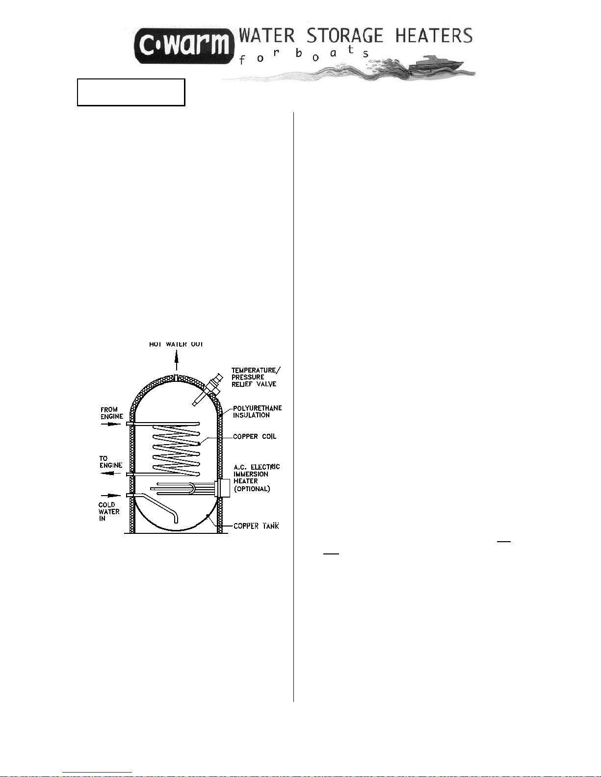
Calorifiers and Water Storage Heaters – what’s the difference?
None. ‘Calorifier’ is a word borrowed from industrial process heating, meaning a water vessel containing
a heat exchanger (such as a coiled pipe) through which steam or hot water passes, giving up its heat to
the water contained in the vessel.

3
A C-Warm water storage heater offers a
simple and convenient means of
enjoying the benefits of stored hot water
on board your vessel, at no extra cost in
fuel.
Installation is straightf orward. Provided a
few simple rules are obeyed, your
heater will give you lengthy service with
virtually no maintenance.
INDIRECT COOLED ENGINE
DIRECT COOLED ENGINE
INTRODUCING YOUR C-WARM WATER STORAGE HEATER (CALORIFIER)
C-Warm storage heaters are designed
for use with INDIRECT MARINE ENGINE
COOLING SYSTEMS using a closed loop
of hot water circulating through the
engine heat exchanger. Twin coil
models may also be used with a second
engine or with gas or diesel burners. A
mains
voltage a.c. immersion heater
can be fitted.
If an auxiliary burner is used follow the
fitting and operating instructions
supplied with it.
With water entering the coil at 82°C, a
C-Warm heater is designed to provide a
full charge of hot water at 60°C w
ithin
15 to 25 minutes. The larger heaters
have more coil turns, so heating time is
virtually independent of the volume of
water contained in the storage heater.
With DIRECT COOLED ENGINES, the
temperature of the water leaving the
engine is more variable
. For effective
use of a storage heater, the
temperature of the water entering the
coil should be at least 50°C.
Before you adapt a new engine’s
cooling circuit to take a water storage
heater, check with your engine supplier
to ensure that you do not inv
alidate the
engine’s warranty.

4
Your C-Warm water storage heater is
part of an unvented (‘closed’)
pressurised water system. Most domestic
systems in the UK are vented to
atmosphere (‘open’). In continental
Europe and elsewhere unvented
domestic systems are the normal type.
With proper protection against
overheating, unvented systems present
no hazard to the user. Safety
precautions are required by law for
unvented systems installed in houses in
the UK. The requirements are set out in
Building Regulations and local Bye-laws.
Although no such regulations exist (at
the time of printing) for unvented
systems in boats, these instructions
describe and recommend precautions
that comply with UK law for domestic
systems.
C-Warm heaters are designed for use
with clean, fresh, drinkable water. Salty
or heavily chlorinated water is more
corrosive than pure water, and the
working life of the heater and its fittings
may be shortened.
Copper is moderately resistant to
corrosion in hot sea water, so the heater
itself can be used with sea water,
though its working life may be
shortened. Because the temp/pressure
relief valve may corrode, C-Warm is not
recommended for sea water use with an
electric immersion heater.
CAN I USE A C-WARM STORAGE HEAT E R TO HEAT SEA WATE R ?
SAFETY
WATER QUALITY
● Fit a C-Warm double-protected electric immersion heater. See page 12
● The temperature/pressure relief valve supplied with your C-Warm water
storage heater MUST be fitted in the heater.
- in the event of overheating due to thermostat failure in an electric
immersion heater, the relief valve will open before the water can boil,
eliminating the risk of a sudden release of large amounts of scalding
water and steam.
- the relief valve protects the storage heater itself from excessive pressure
and possible damage caused by hot water expansion or by failure of
the pressure switch on the pump.
Some additional precautions are noted in the text. These precautions are
marked as shown:
ESSENTIAL PRECAUTIONS

5
The schematic diagram shows the installation principle. Contact your engine
supplier for advice about the recommended connection points on your engine.
INDIRECT CO OLED ENGINE
For maximum flow through the coil, the
inlet connection should be close to the
engine (A) and the discharge
connection should be close to the
circulation pump (D). Somewhat less
flow through the coil can be attained, if
required, by taking off hot water from a
point (B) downstream of (A) and
returning it to point (C) upstream of (D),
so that the pressure difference between
the coil take-off and return is a little less.
DIRECT COOLED ENGINE
Some direct-cooled engines provide for
a relatively high engine block
temperature. The recommended
connection points for the C-Warm
heating coil will vary according to the
engine design. Check your engine
manual and if necessary contact your
engine supplier for advice
ADAPTING THE ENGINE COOLING CIRCUIT

6
I. Check that you have received
the correct C-Warm heater and
accessories. Check immersion
heater power and voltage.
Report any damage or
discrepancies to your supplier
without delay.
II. Check the dimensions of the
heater and recheck the
dimensions of the space for its
installation in your boat.
III. Read through these instructions
carefully, noting additional items
required for installation.
Your C-Warm water storage heater may be located in any convenient and
accessible position subject to the following considerations:
I. With pumped cooling water
circulation, the storage heater
can be located above or below
engine level. For best circulation,
natural convection should assist
the pumped flow.
II. There must be no air locks in the
cooling water circuit. Either
locate the water storage heater
with its upper coil connection
below the engine’s water filling
point, or fit an auxiliary
header/filler tank above the
highest point in the cooling water
circuit. See page 7.
III. The longer the pipe run
between water storage heater
and engine, the more work the
engine’s cooling water
circulation pump has to do.
Minimise the reduction in water
flow rate by locating the
storage heater near the engine.
IV. Vertical C-Warm storage heaters
MUST be mounted vertically,
horizontal heaters MUST be
mounted horizontally.
BEFORE YOU START
LOCATION

7
For installations where the upper coil connection is above the level of the engine’s
water filling point.
How to fit an auxiliary header tank if necessary
1. Blank the existing header tank by
using a flat cap that does not
obstruct the overflow pipe.
2.
Fit a new expansion tank nearby, at
a height just above the top of the CWarm water storage heater coil.
Connect it to the overflow outlet on
the original header tank, using a
suitable pressure hose (see diagram
)
The expansion tank for a car radiator
is suitable for engine cooling systems
up to about 200 litres in total volume.
3.
Fit an air bleed close to the top coil
connection of the water storage
heater. On filling the system with
water, ensure that all the air in the
cooling circuit escapes via this bleed
or from the engine.
4.
On starting the engine check for loss
of liquid and for air locks in the
extended cooling circuit.
6
4

8
FIXING THE WAT E R STO RAGE HEATER IN PL ACE
When full of water the heater has a substantial mass. It must be secured firmly in
place to prevent damage to the heater and pipework or to the supporting
structure, from the effects of rough weather or other shocks of marine use.
1. Support the WEIGHT on a strong bas e
2 Support the MASS against horizontal forces
The exact method you use to hold the heater in place will depend on the
construction of the vessel and on the available space.
Some suggested installation methods are indicated below.
VERTICAL MODELS
1 litre of water
weighs 1 kg
Locate the heater on a firm level base strong enough to
support at least twice the weight of the (full) heater
Either
: construct suitable supports to hold the heater in
place
or: use one or more restraining straps as shown be
low
BRACKET KIT
CWAB-V series
contains:
1 bracket assembly
or…
STRAP KIT
CWA-STRKIT
contains:
2 webbing straps
4 stainless steel brackets
Instructions for use
Use…
BRACKET
ASSEMBLY
BRACKETS
WEBBING STRAPS
WITH BUCKLES

9
BRACKET KIT
CWAB-H series
contains:
2 bracket assemblies
STRAP KIT
CWA-STRKIT
contains:
2 webbing straps
4 stainless steel brackets
Instructions for use
or…
Use…
Either a C-Warm Strap Kit or a C-Warm Bracket Kit (H-series) can be used to secure
the heater in place. Leave space under the heater for pipe connections on some
models. See dimensions page 23.
HORIZONTAL MODELS

CONNECTING THE PIPEWORK
C-Warm heaters may be connected
into the engine cooling and pressurised
water systems with any suitable pipe
material. Most commonly used are:
Hep2O push-fit piping system
Hep2 O CONNECTION KITS are available
for all C-Warm heaters. See C-Warm
Selection guide for details. The kit
contains Hep2 O fittings for the
pressurised water connections and brass
hose connections to the heating coil.
Copper pipe
Connecting the coil into the engine
cooling circuit
Use ½” or ¾” bore rubber (car or lorry)
heater hose, obtainable from vehicle
accessory suppliers. This will minimise
the engine vibration reaching the
heater.
Connect the coil into the engine cooling
circuit and/or auxiliary heater. Fasten
the hose securely to the connectors
using stainless steel hose clips. Do not
allow loops of hose to form air locks.
If copper pipework is preferred for the
pressurised water connections, suitable
adapters and compression fittings
should be used. These may be
obtained from a plumber’s merchant or
from most ‘Do-it-Yourself’ stores. See
pages 18 - 20 for connection sizes.
The pipework connections to the heater
must not be stressed. Make sure that
the copper pipework is fully supported
Flexible hose
If flexible hose is preferred for the
pressurised hot and cold water
connections, suitable connectors will be
required. Use opaque hose (to
discourage algal growth) and stainless
steel hose clips. See pages 18 - 20 for
connection sizes.
Do not over-tighten
the coil connections.
Over-tightening may
distort the copper
wall of the storage
heater, causing
immediate or
eventual leakage.
Max. torque should
not exceed 70Nm
(50lb.ft)
l The heating coil may safely remain
incorporated into the engine
cooling circuit whether the heater
itself is full of water, partly full or
empty.
l The coils in a twin-coil C-Warm
heater are completely independent
in operation. The water storage
heater will work satisfactorily with
either coil alone or with both coils
together in use.
10

Connecting the cold water inlet and
the hot water outlet into your
pressurised water system
C-Warm heaters with ½” BSP
connections require 15mm bore
pipework; models with ¾” BSP
connections require 22mm pipework.
See page 18 - 20 for connection sizes.
C-Warm CONNECTION KITS contain
connectors suitable for Hep2 o (ACORN)
push-fit pipework.
•
The cold water inlet line should be
fitted with a drain cock, close to the
heater, to allow drainage if
maintenance becomes necessary,
and to avoid the risk of freezing in the
winter.
Fitting the temperature-and-pressure
relief valve
See pages 18 to 20 for the correct
location of the relief valve on your
heater.
Ensure that the coloured knob on the
valve is in an accessible position. The
discharge port of the valve must point
downwards, with a suitable hose to
allow hot water or steam to escape
safely to the bilge or another suitable
area.
The relief valve supplied with the heater
is non-adjustable and is pre-set to lift at
3bar (44psi) or at 90°C.
WARNING
The temperature-and-pressure-
relief valve is essential for the safe
operation of your C-Warm heater.
Failure to fit the relief valve, or any
alteration to or interference with its
function, or fitting of any valve
other than that supplied with the
heater, carries a risk of serious
personal injury or death in the
event of overheating. It will also
invalidate the supplier’s warranty.
Marine pressurised water pumps
normally have pressure switches set to
cut out below 2.5bar (36psi). Check
that your pressure switch cuts out at or
below this pressure. Use of a pressure
switch cutting out at or close to 3bar
(44psi) could lead to continuous
discharge of water through the relief
valve.
11

FITTING AN ELECTRIC IMMERSION HEATER
Before fitting the immersion heater,
check that your a.c. supply voltage
corresponds to that indicated on the
immersion heater. Remove the dummy
boss from the calorifier.
AVOID LEAKS - make sure all surfaces
are clean! Clean the seating surface on
the calorifier boss, and the screw
threads on the boss and the immersion
heater. Lightly coat the ‘O’ ring and
threads on the calorifier and immersion
heater with silicone grease.
Screw in the heater. Remove the heater
cover, bend the cable to one side, fit a
2¼” box spanner over the hexagonal
base of the heater, and tighten
carefully.
To make the electrical connections,
follow the wiring instructions on page 13.
The use of a standard domestic
immersion heater with a single
thermostat is not recommended.
A Cleghorn Waring double-protected immersion heater, fitted with a hightemperature cut-out in addition to the control thermostat, is strongly
recommended. Should the control thermostat fail, the high-temperature cutout will isolate the immersion heater when the water temperature reaches 90°C.
Thermostat Settings
The control thermostat on the immersion
heater is pre-set to cut out when the
water temperature reaches 60°C. This is
ample for domestic use. In an attempt
to reduce the likelihood of scalding, we
recommend that the control thermostat
is set no higher than 65ºC
The high temperature cut-out thermostat
is adjustable up to a maximum of 85°C.
It is pre-set to 85°C.
Check the thermostat settings before
using your immersion heater for the first
time. Isolate the immersion heater from
its power supply before removing the
cover. If necessary adjust the control
thermostat setting by turning the dial
with a screwdriver blade until the arrow
points to the desired temperature.
DO NOT set the high temperature cutout to operate below the cut-out
temperature of the control thermostat.
CONTROL THERMOSTAT DIAL
40ºC = 104ºF
50ºC = 122ºF
60ºC = 140ºF
70ºC = 158ºF
80ºC = 176ºF
Screwdriver Slot
In the event of a high temperature cutout the system should be thoroughly
checked before the manual re-set
button is pushed. It is advisable to
replace the control thermostat before
the immersion heater is used again.
Contact your supplier for a replacement
thermostat.
12

13
Wiring Instructions
1. It is essential that the correct
size of fuse or circuit breaker be
fitted.
2. Check that the mains supply
voltage corresponds with the
voltage indicated on the
heater.
3. Isolate the electrical supply to
the cable.
4. Make the supply cable
connections as follows.
Standard colours in the UK are:
Brown = Live
Blue = Neutral
Green/Yellow = Earth
THE IMMERSION HEATER
MUST BE EARTHED
Before you switch on the immersion
heater, check that the water storage
heater is full of water, and that the
temperature-and-pressure relief valve
has been properly fitted.
IF YOU ARE IN ANY DOUBT ABOUT FITTING
THE IMMERSION HEATER, OBTAIN THE
SERVICES OF A QUALIFIED ELECTRICIAN.
Wiring diagram for a Cleghorn Waring
double-protected Immersion Heater
Model Number CW279
2kW
Voltage = 220-240 v a.c.
Recommended fuse: 10 amp
Model Number CW278
1.25kW
Voltage = 220-240 v a.c.
Recommended fuse: 5 amp
Model Number CW240
0.75kW
Voltage = 220-240 v a.c.
Recommended fuse: 3 amp
Model Number CW239
1kW
Voltage = 110-115 v a.c.
Recommended fuse: 10 amp
IF AN ELECTRIC IMMERSION HEATER IS NOT FITTED
boss
washer
plug
1. Before you install and fill the
heater…unscrew the plug
from the immersion heater
boss
2.
Check that the faces of the
plug, the boss and the
sealing washer are clean
and undamaged. Apply a
small quantity of silicone
grease to each face
3. Screw the boss
firmly into
position.
Do not over
tighten. (Max
torque =70Nm)
High tempera tu r e
Cut
-out set to 85ºC

14
C-Warm storage heaters are highly efficient, and the stored water can reach
almost the same temperature as the water in the engine cooling circuit. (90°-95°C).
Domestic hot water is not normally hotter than 60°C.
C-Warm’s efficient insulation will keep your stored water hot for many hours after
the engine has stopped
Legionella bacteria occur naturally in many water systems. People exposed to them can develop
Legionnaire’s disease.
Water temperature Risk
Above 60ºC Can scald, but Legionella bacteria cannot survive
20º to 45ºC Legionella multiply
Below 20ºC Legionella will not multiply but remain a potential threat
Store hot water at 60º or above. Use a blender valve in the hot water supply line to add cold water
in controlled amounts.
REGULATING THE TEMPERATURE OF THE ENGINE HEATED WATER
You can limit the temperature of the hot
water supply by:
l
fitting a C-Warm adjustable thermostat,
model CW276A. This also avoids the
possibility of tripping the high
temperature cut-out in a C-Warm
double-protected electric immersion
heater if the stored water temperature
reaches 90°C. Do not use on direct
cooled engines
l
fitting a blender valve in the hot water
discharge line, to add a controllable
proportion of cold water. This method
has the potential advantage o f
extending the capacity of the C-Warm
heater (X litres of water at 85°C plus Y
litres of cold water = X + Y litres of water
at 55°C)
MAKING SURE YOUR WATER STAYS HOT
l Long pipe runs can delay the arrival of hot water at the hot taps, wasting water.
Heat loss can be minimised by insulating the hot water pipes.
l
Occasionally a thermo-syphon will start of its own accord in the engine cooling
circuit, silently extracting heat from your stored water and warming the
(stationary) engine! This is an unlikely event, but if it does happen, contact your
C-Warm supplier for advice.
TOO HOT? TOO COLD? A HEALTH NOTE
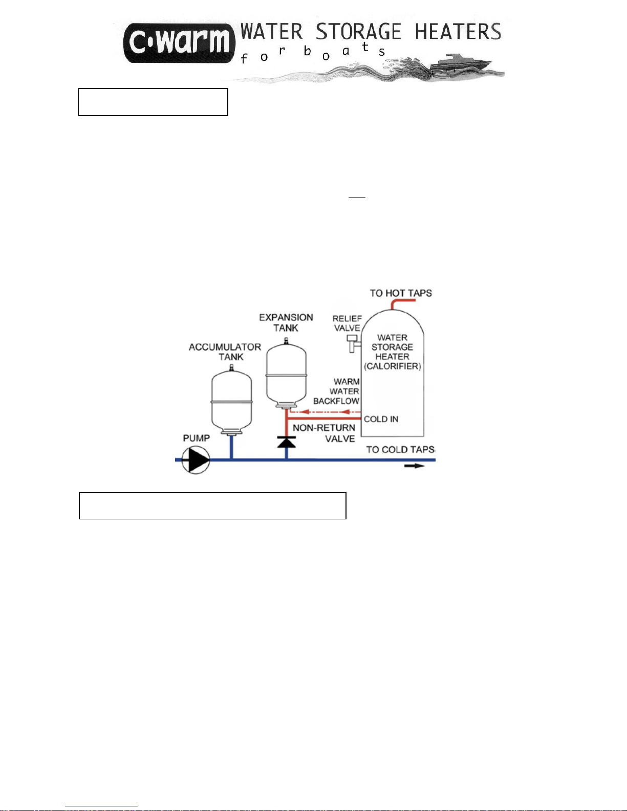
HOT WATER EXPANSION
The water in your C-Warm storage heater expands as it heats up. Provided your pressurised
system incorporates an accumulator tank, this expansion will be absorbed as it takes place.
In the process, a small amount of hot water may flow back into the cold water line. If hot
water backflow cannot be tolerated, fit a non-return valve and a separate expansion tank
in the cold water supply line to the heater.
Set the gas pressure in the expansion tank to the cut-out pressure of the pump.
If your system has no accumulator or e xpansion tank, thermal expansion will cause the
temperature-and-pressure relief valve to discharge a little hot water every time the stored
water is heated. The valve includes a hose connector to allow this water to be drained into
the bilge. Eventually, a deposit of scale may build up in the relief valve, preventing it from
closing fully. An expansion tank is recommended for this reason.
REGULATING THE COLD WATER INLET PRESSURE
Where the cut-out pressure of the pressure system pump exceeds or is close to the pressure
of the temperature-and-pressure relief valve (TPRV), a PRESSURE REDUCING VALVE is
required in the cold water inlet to the water storage heater
Expansion tank
When a Pressure-Reducing Valve is fitted, it is necessary to fit an expansion tank (Why? See
above). The gas pressure in the expansion tank should be the same as the setting of the
Pressure-Reducing Valve. This should be done before the system is pressurised by the
pump.
Selecting a Pressure-Reducing Valve and an Expansion Tank
Please contact Cleghorn Waring to establish the correct size of expansion tank and the
correct pressure setting for the Pressure-Reducing Valve. You will need to know the
capacity of your water storage heater and the pressure rating of the TPRV.
Using a Pressure-Reducing Valve in conjunction with a Blender Valve
If a blender valve is to be fitted, its cold water inlet should be connected into the pipework
between the Pressure-Reducing Valve and the cold inlet fitting on your hot water storage
tank
15
16
1 Check that the pipework is complete
and fully connected.
2 If necessary, refill the engine coo l ing
system with the recommen ded
coolant.
3 To fill your pressurised water system,
including your C-Warm heater, w ith
water proceed as follows:
● check that the pipe work is
complete and fully connected
● open all the hot and cold outlets
● fill the cold water supply tan k
● open the isolating valv e fro m t he
water supply tank to the
pressurised system
● start the pump, which should prime
itself in a few seconds. The system
will begin to fill with water. As the
system fills up, the t aps will start to
discharge air and water. Close
each tap slowly, until only one hot
tap remains open. When this ta p
stops discharging air, the C-Warm
heater is full. Close the t ap. T h e
pump will stop within a short time.
● check all the fittings and
connections thoroughly for leaks
● test the temperature-and-pressure
relief valve by rotating th e coloured
knob one full turn anticlockwise;
water should flow freely from the
valve discharge
● refill your water storage tank
● check all the connections once more
when the water is heated for th e fi rst
time.
4. Your pressurised system and C-Warm
heater are now ready fo r use.
5. Your engine cooling circuit will heat the
stored fresh water in your C-Warm
heater automatically, whenever you run
the engine. The engine cannot
overheat C-Warm: once t he st ored
water has reached its maximum
temperature, no added heat is
absorbed from the engine coo ling
circuit.
6. C-Warm’s efficient instal lation will keep
the stored water hot for many h o urs after
you have stopped the engin e
7. If the stored water is too hot, check the
C-Warm Instructions to find out how to
limit its temperature
8. An electric immersion h e a t er will swit ch
itself on and off automatically, just as in
a domestic water tank. Reset t he m ain
thermostat in the immers ion h eater if
necessary (factory setting is 60ºC). Do
not adjust the high temperatu re cut-out
thermostat (factory setting is 85ºC).
9. Use your hot and cold water outlets just
as you would at home.
10. Apart from checking the operation of
the temperature-and-pressure relief
valve once a week (see instructions)
your C-Warm storage heater needs no
regular maintenance. Don’t forget to
drain it when you store the boat for the
winter!
USING THE HEATER
17
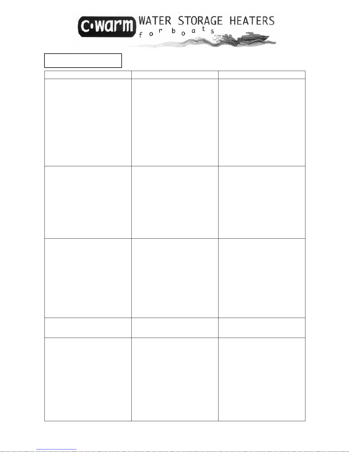
PROBLEM
POSSIBLE CAUSE
ACTION
Water not hot enough
Coil inlet temperature too low
Air lock(s) in engine cooling
circuit
Top of storage heater above
engine cooling header tank
Thermostat in engine cooling
circuit not adjusted correctly
Thermo-syphon in coil circuit
when engine is not running
Check coil inlet water
temperature and correct if
necessary
Check for air locks
Raise header tank
Check setting on thermostat
Contact your supplier for advice
Water too hot
Engine cooling circuit water too
hot
Immersion heater control
thermostat set too high
Immersion heater control
thermostat has failed
Fit thermostat CW276A or
blender valve CW268 OR
CW272B
Adjust immersion heater control
thermostat
Check control thermostat.
Do not reset high temperature
cut-out until the cause of the
overheating has been
established
Water discharges continuously
through temperature/pressure
relief valve
Pump pressure switch cut-out
setting is higher than relief valve
setting.
Pressure switch has failed
Stored water too hot
Immersion heater control
thermostat set too high or has
failed.
Temperature/pressure relief
valve has failed
Check cut-out setting. Adjust or
replace switch, or fit pressurereducing valve
Replace pressure switch
Fit thermostat CW276A
Adjust or replace control and
high temp. thermostats
Replace temperature/pressure
relief valve
Hot water flows back into cold
water line
Thermal expansion
Fit non-return valve and
expansion tank, as outlined in
these instructions
Immersion heater does not
operate
Electric supply failure
Control thermostat temperature
set too low.
High temperature cut-out has
operated
Restore electric supply.
Check control thermostat and
correct if necessary.
Check control thermostat and
replace if necessary.
Inspect system before using
heater again.
Check that high temperature
cut-out setting is above control
thermostat setting: reset at 90ºC
PROBLEM SOLVING
18
C-Warm
Model
No
H= horizontal
V= vertical
T= twin coil
Capacity litres
A B C
D1
D2
E1
E2
F
Hot
water
outlet
cold
water
inlet
relief
valve
coil
inlet
coil
outlet
2nd coil
inlet
2nd coil
outlet
Imm.
heater
BSP
(gas)
thread
BSP
(gas)
thread
BSP
(gas)
thread
BSP
(gas)
thread
BSP
(gas)
thread
BSP
(gas)
thread
BSP
(gas)
thread
BSP
(gas)
thread
ext.
ext.
int.
ext.
ext.
ext.
ext.
int.
CWM18-H3 18 ½” ½” ½” ¾” ¾” - - 2¼”
CWM21-V3 20 ½” int. ½” int. ½” ¾” ¾” - - 2¼”
CWM29-V3 29 ½” ½” ½” ¾” ¾” - - 2¼”
CWM29-VT3 29 ½”
½” ½” ¾” ¾” ¾” ¾”
2¼”
CWM32-H3 32 ½” ½” ½” ¾” ¾” - - 2¼”
CWM40-V3 40 ½” int. ½” int. ½” ¾” ¾” - - 2¼”
CWM41-H3 40 ½”int. ½”int. ½” ¾” ¾” - - 2¼”
CWM41-HT3 40 ½”int. ½”int.
½” ¾” ¾” ¾” ¾”
2¼”
CWM45-H3 45 ½” ½” ½” ¾” ¾” - - 2¼”
CWM50-V3 50 ½” ½” ½” ¾” ¾” - - 2¼”
CWM50-VT3 50 ½” ½” ½” ¾” ¾” ¾” ¾” 2¼”
CWM50-H3 50 ½”
½” ½” ¾” ¾”
- - 2¼”
CWM50-HT3 50 ½” ½” ½” ¾” ¾” ¾” ¾” 2¼”
CWM53-H3 53 ½” ½” ½” ¾” ¾” - - 2¼”
CWM53-HT3 53 ½” ½” ½” ¾” ¾” ¾” ¾” 2¼”
CWM53-V3 53 ½”
½” ½” ¾” ¾”
- - 2¼”
CWM53-VT3 53 ½” ½” ½” ¾” ¾” ¾” ¾” 2¼”
CWM64-H3 67 ¾”int. ¾”int.
½” ¾” ¾” - - 2¼”
CWM64-HT3 67 ¾”int. ¾”int.
½” ¾” ¾” ¾” ¾” 2¼”
CWM67-V3 67 ¾” ¾”
½” ¾” ¾”
- - 2¼”
CWM67-VT3 67 ¾” ¾”
½” ¾” ¾” ¾” ¾” 2¼”
CWM73-H3 73 ¾”int. ¾”int.
½” ¾” ¾” - - 2¼”
CWM73-HT3 73 ¾”int. ¾”int.
½” ¾” ¾” ¾” ¾” 2¼”
CWM78-V3 78 ¾” ¾”
½” ¾” ¾”
- - 2¼”
CWM78VT3 78 ¾” ¾”
½” ¾” ¾” ¾” ¾” 2¼”
CWM93-V3 93 ¾” ¾”
½” ¾” ¾” - - 2¼”
CWM93-VT3 93 ¾” ¾”
½” ¾” ¾” ¾” ¾” 2¼”
CWM141-V3 141 ¾” ¾”
½” ¾” ¾”
- - 2¼”
CWM141-VT3 141 ¾” ¾”
½” ¾” ¾” ¾” ¾” 2¼”
CONNECTIONS

19
See Table, page 18 NOT TO SCALE
HORIZONTAL MODELS

20
See Table, page 18 NOT TO SCALE
VERTICAL MODELS

WARRANTY
We warrant that all new equipment sold by us is free from defects in material or workmanship. Our liability under this warranty is limited
to making good any part or parts which shall be within one year from the date when the equipment was delivered new to the customer be
returned to us and which we are satisfied on our examination to have been defective in material or workmanship. Included in this
warranty are the costs of labour incurred by us in making good such part or parts.
This warranty is given on condition that:
i we are notified in writing within fourteen days after such defects appear and the equipment or defective parts are returned to as
soon as reasonably practical or where this is not practical made available for inspection by us
ii t he equi pm ent has in our judgement been correct l y install ed and norm ally used in accordance with the instructi ons provided f or its
installation operation and maintenance
iii unless performance figures and performance tolerances have been stipulated by the purchaser and agreed by us at the time of
ordering the equipment we shall be under no liability in the absence of any defect in material or workmanship for failure to obtain
any particular performance
iv if the equipment has in our judgement been altered taken apart repaired tampered with neglected damaged or used in any way
so as adversely to affect its performance or condition we shall not be liable for any fault arising from its use
v we shall not be liable for faults arising from the use of any spare or replacement parts not authorised or recommended by us
vi any equipment or defective part replaced by us shall become our property
vii the decisi on whether to repair or replace a defective part under warranty claim shall be at our discretion
viii excluded from this warranty are any parts which need replacement due to normal wear and tear
ix carriage to our works of any equipment or parts returned to us under a warranty claim shall be the responsibility of and at the
expense of the claimant
x we accept no responsibility for loss or damage howsoever occasioned to customers’ goods whilst such goods are in transit to or
from ourselves or in the possession of or in transit to or from our agents
xi we give no warranty in respect of equipment supplied by us except the foregoing warranty and without prejudice t o the generality
of the foregoing we shall be under no liability whether in contract or otherwise in respect of any defects in the goods or from any
injury loss or damage resulting from such defects or from any work done in connection therewith and we shall not in any
circumstances be liable for any consequential loss or damage suffered including any loss of use loss of contract or loss of profits.
Our liability shall in no case exceed the value of goods in relation to which the claim is made
xii the purchaser acknowledges that the equipment is sold to him in consideration of payment of the price and of the undertaking of
the part of the purchaser to
a) obs erve all prudent trade practices in relation to installation and user so that the equipment is not used when it is in an
unsafe condition for whatsoever reason
b) ens ure i n so far as the equipment is incorporated i nto ot her equi pment that such other equipment is in good working
order and that such incorporation is in accordance with what the manufacturer would require
c) ensure that his staff and all users of the equipment are adequately informed of their duties in relation to use of the
equipment
d) obs erve t he Heal th and Safety at Work legislation as amended from time to time in relation to the equipment supplied so
that we shall not be liable in any respect as a result of the purchaser’s failure to observe the conditions a) to d) set out
above.
The foregoing warranty is given without prejudice to purchasers’ statutory rights.
MANUFACTURED IN THE UK FOR:
Xylem Water Solutions UK Ltd
Bingley Road
Hoddesdon
Hertfordshire
EN11 0BU
UK
Telephone: +44 (0)1462 480380
Fax: +44 (0)1462 482422
www.jabscoshop.com
e-mail: mail@jabsco.co.uk
 Loading...