


S-20
Safety manual
Sicherheitshandbuch
Manuel de sécurité
Manual de seguridad
Safety manual on functional safety, model S-20
Sicherheitshandbuch zur funktionalen Sicherheit, Typ S-20
Manuel de sécurité concernant la sécurité fonctionnelle, type S-20
Manual de seguridad para seguridad funcional, modelo S-20
Pressure transmitter model S-20
GB
D
F
E

GB
Safety manual, model S-20 Page 3 - 14
D
Sicherheitshandbuch, Typ S-20 Seite 15 - 25
F
Manuel de sécurité, type S-20 Page 27 - 38
E
Manual de seguridad, modelo S-20 Página 39 - 49
© 2014 WIKA Alexander Wiegand SE & Co. KG
All rights reserved. / Alle Rechte vorbehalten.
®
is a registered trademark in various countries.
WIKA
®
ist eine geschützte Marke in verschiedenen Ländern.
WIKA
Prior to starting any work, read the operating instructions!
Keep for later use!
Vor Beginn aller Arbeiten Betriebsanleitung lesen!
Zum späteren Gebrauch aufbewahren!
Lire le mode d'emploi avant de commencer toute opération !
A conserver pour une utilisation ultérieure !
¡Leer el manual de instrucciones antes de comenzar cualquier trabajo!
¡Guardar el manual para una eventual consulta posterior!
2
WIKA Safety manual pressure transmitter, model S-20
14082128.02 06/2014 GB/D/F/E
Contents
Contents
1. General information 4
1.1 Purpose of this document 4
1.2 Other applicable instrument documentation 4
1.3 Relevant standards 4
1.4 Abbreviations 5
2. Safety 6
2.1 Pressure ranges 6
2.2 Labelling, safety marks 6
2.3 Pin assignment 7
2.4 Output signal/current parameters 7
2.5 Description of the safety function and diagnosis 9
2.6 Test to discover a signal drift 10
2.7 Information on the determination of safety-relevant parameters 11
2.8 Limits of operation (including ambient conditions) 11
2.9 EMC 12
2.10 Commissioning of the pressure transmitter 12
2.11 Decommissioning of the pressure transmitter 13
2.12 Corrective maintenance 13
2.13 Performance level key gures 13
GB
14082128.02 06/2014 GB/D/F/E
WIKA Safety manual pressure transmitter, model S-20
3

1. General information
1. General information
1.1 Purpose of this document
This safety manual for functional safety is concerned with the model S-20 pressure transmitter only as a component
GB
of a safety function. This safety manual applies in conjunction with the documentation mentioned under chapter
1.2 “Other applicable instrument documentation”. In addition, the safety instructions in the operating instructions
(article number 14043170) must be observed.
The operating instructions contain important information on handling the model S-20 pressure transmitter. Working
safely requires that all safety instructions and work instructions are observed.
Application range
The model S-20 pressure transmitter has been designed for universal application in machine building and plant construction. The operator has to ensure a regular change in pressure and with that a proportional change in output signal.
The pressure transmitter, due to the selected performance level, does not provide a diagnostic function to detect a
static signal due to an instrument failure.
1.2 Other applicable instrument documentation
In addition to this safety manual the operating instructions (article number 14043170) and the data sheet PE 81.61 are
applicable for model S-20.
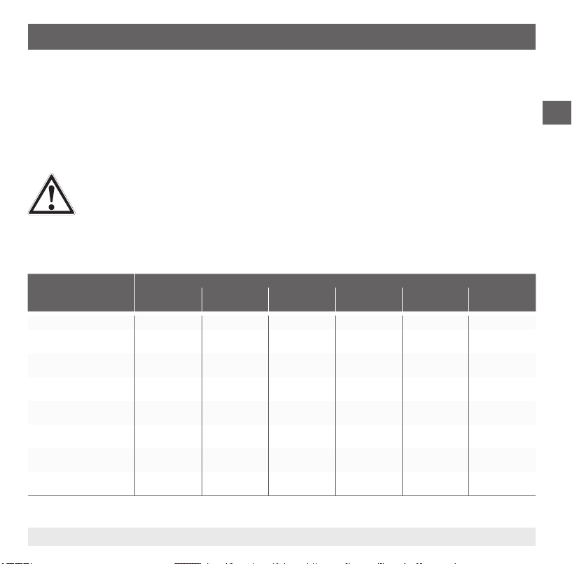
1.3 Relevant standards
Standard Description
EN ISO 13849-1:2008 Safety of machinery - Safety-related components of control systems
EN ISO 13849-2:2012 Safety of machinery - Safety-related components of control systems
EN 61326-3-1:2008 Electrical equipment for measurement, control and laboratory use - EMC requirements
Table 1-1: Relevant standards
Part 1: General principles for design (ISO 13849-1:2006);
Part 2: Validation (ISO 13849-2:2012)
Part 3-1: Interference immunity requirements for safety-related systems and for equipment intended to
perform safety-related functions (functional safety) - General industrial applications
4
WIKA Safety manual pressure transmitter, model S-20
14082128.02 06/2014 GB/D/F/E

1. General information
1.4 Abbreviations
Abbreviation Description
FMEA Failure Modes Eects and Diagnostic Analysis
MTTFd Expected value of the mean time to dangerous failure
PL Performance level: Discrete level which species the ability of safety-related parts of control systems to perform a
TM Service life
Settling time Time period between the step change in the pressure signal and the time at which the output signal deviates by no
Switch-on time Time after power-on until the rst valid measured value (max. ±1% FSO error) is present at the signal output.
Table 1-2: Abbreviations (see also EN ISO 13849-1:2008 and EN ISO 13849-2:2012)
safety function under foreseeable conditions.
more than 1 % tolerance from the value of the nal stable condition.
GB
14082128.02 06/2014 GB/D/F/E
WIKA Safety manual pressure transmitter, model S-20
5
2. Safety
2. Safety
2.1 Pressure ranges
The permissible pressure range for the pressure transmitter can be found on the product label.
GB
WARNING!
■
The overload pressure must never be exceeded, even when failures occur. Loading over the overload
pressure can cause measuring errors in the output signal and thus impair the safety function.
■
Pressure surges below the nominal pressure and lasting less than 1 ms can cause measuring errors
in the output signal and thus impair the safety function. For this, optional pressure ports with a smaller
diameter are available to reduce pressure surges. It is important to ensure that the reduced diameter
is suitable for the particle sizes within the medium.
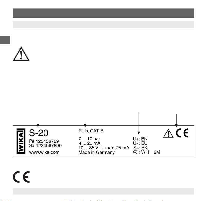
2.2 Labelling, safety marks
Product label
Model
P# product number
S# serial number
Explanation of symbols
CE, Communauté Européenne
Instruments bearing this mark comply with the relevant European directives.
6
Performance Level
Measuring range
Output signal
Power supply
Pin assignment see explanation of
symbols
WIKA Safety manual pressure transmitter, model S-20
14082128.02 06/2014 GB/D/F/E
2. Safety
2.3 Pin assignment
The assignment of the connection pins to the signals, and also the scaling of the signals, can be found on the product
label.
■
Connection 0 V / U-: Common terminal for negative operating voltage and signal ground.
■
Connection U+: Positive operating voltage
■
Connection S+: Signal output for voltage outputs
WARNING!
For instruments with plug-in electrical connections, the suitable connector must be used. The ingress of
moisture must be reliably prevented. The notes on commissioning in the operating instructions must be
observed.
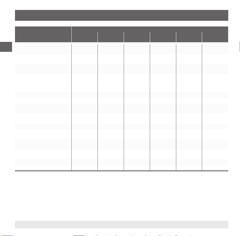
2.4 Output signal/current parameters
GB
Parameter Output signal
Span range 16 mA 16 mA 4 V 5 V 4 V 4 V * U
Control range lower limit
value
Span
Initial limit value
Span
Initial nominal value
Span
Final nominal value
Span
Final limit value
Control range upper limit
value
Nominal operating voltage
[V DC]
U
B
14082128.02 06/2014 GB/D/F/E
4 ... 20 mA
(2-wire)
3.6 mA 23 mA -0.4 V -0.4 V -0.4 V 0.1 * U
3.8 mA 20.5 mA 0.9 V 0.9 V 0.4 V 0.4 V * U
4 mA 20 mA 1 V 1 V 0.5 V 0.5 * U
20 mA 4 mA 5 V 6V 4.5 V 4.5 * U
20.5 mA 3.8 mA 5.5 V 6.5 V 4.7 V 4.7 V * U
23 mA 3.6 mA 11.5 V 11.5 V 11.5 V 4.9 * U
24 24 24 24 24 5
20 … 4 mA
(2-wire)
DC 1 … 5 V DC 1 … 6 V DC 0.5 … 4.5 V DC 0.5 … 4.5 V
WIKA Safety manual pressure transmitter, model S-20
ratiometric
B
B
B
B
B
/ 5 V
/ 5 V
B
/ 5 V
/ 5 V
B
/ 5 V
/ 5 V
/ 5 V
7
2. Safety
Parameter Output signal
Minimum operating voltage U
GB
[V DC]
Maximum operating voltage UB
[V DC]
Operating voltage U
maximum [V DC]
Maximum ripple in the operating
voltage [% of V DC ] Frequency
range with 50 Hz, 60 Hz, 100 Hz,
120 Hz
Maximum current supply [mA] 25 25 12 12 12 12
Dissipation loss
Operating voltage inuence
[% every 10 V]
Load maximum [Ω] ≥ (U
Maximum load capacitance [nF] N/A N/A 100 100 100 0.47
Reverse polarity protection
between U
Short-circuit resistance between
S
+/UB+
Short-circuit resistance between
S
+/UB-
Settling time [ms] 3 3 3 3 3 3
Switch-on time [ms] 150 150 150 150 150 150
Table 2-1: Parameters
B+/UB-
[mW]
absolute
B
4 ... 20 mA
(2-wire)
8 8 8 9 8 4.5
B
36
(35 with cULus)36(35 with cULus)36(35 with cULus)36(35 with cULus)36(35 with cULus)
40 40 40 40 40 5.5
±0.5 ±0.5 ±0.5 ±0.5 ±0.5 N/A
828 828 432 432 432 432
±0.05 ±0.05 ±0.05 ±0.05 ±0.05 N/A
- 7.5 V) /
B
0.023 A
yes yes yes yes yes no
N/A N/A no no no no
N/A N/A yes yes yes yes
20 … 4 mA
(2-wire)
≥ (UB - 7.5 V) /
0.023 A
DC 1 … 5 V DC 1 … 6 V DC 0.5 …
≤ 5,000 ≤ 6,000 ≤ 4,500 ≤ 4,500
4.5 V
DC 0.5 … 4.5
V ratiometric
5.5
8
WIKA Safety manual pressure transmitter, model S-20
14082128.02 06/2014 GB/D/F/E

2. Safety
2.5 Description of the safety function and diagnosis
The safety function of the model S-20 is that the pressure transmitter converts the physical input parameter of pressure
into an electrical signal.
■
The model S-20 recognises the following error states
GB
Error detection Output signal
Cyclical testing
Underpressure from which
on the error is detected
Overpressure from which on
the error is detected
ADC communication error
(within the instrument)
Testing on switch-on
Sensor error, EEPROM
checksum error (hardware
error detected by
instrument)
Table 2-2: Error detection
■
All failures detected are indicated as downscale alarm signals (low alarm values).
■
Undetected errors can generate an undened output signal within or outside of the span range.
■
The alarm signal for over- or underpressure is triggered when the error condition exists uninterrupted for a minimum
4 ... 20 mA
(2-wire)
-2.5 %
Low alarm value
max. 3.6 mA
+6.25%
Low alarm value
max. 3.6 mA
Low alarm value
max. 3.6 mA
Low alarm value
max. 3.6 mA
20 … 4 mA
(2-wire)
-6.25 %
Low alarm value
max. 3.6 mA
+2.5 %
Low alarm value
max. 3.6 mA
Low alarm value
max. 3.6 mA
Low alarm value
max. 3.6 mA
DC 1 … 5 V DC 1 … 6 V DC 0.5 … 4.5 V DC 0.5 … 4.5 V
-12.5 %
Low alarm value
0.2 … 0.5 V
+25 %
Low alarm value
0.2 … 0.5 V
Low alarm value
0.2 … 0.5 V
Low alarm value
0.2 … 0.5 V
-10 %
Low alarm value
0.2 … 0.5
+20 %
Low alarm value
0.2 … 0.5 V
Low alarm value
0.2 … 0.5 V
Low alarm value
0.2 … 0.5 V
-5 %
Low alarm value
0.1 … 0.3 V
+10 %
Low alarm value
0.1 … 0.3 V
Low alarm value
0.1 … 0.3 V
Low alarm value
0.1 … 0.3 V
ratiometric
-5 %
Low alarm value
0.1 … 0.3 V
+10 %
Low alarm value
0.1 … 0.3 V
Low alarm value
0.1 … 0.3 V
Low alarm value
0.1 … 0.3 V
of 10 seconds.
■
Errors which are checked cyclically are not permanently active, i.e. a reentry into measuring mode after exiting the
error range is possible during running.
■
Missing short-circuit resistance between signals in accordance with table 2-1: Parameters can lead to the destruction of the pressure measuring instrument. Short circuit leads to the loss of the safety function.
■
The external supervisory logic unit must bring the plant to a safe state if the alarm condition is entered.
14082128.02 06/2014 GB/D/F/E
WIKA Safety manual pressure transmitter, model S-20
9
2. Safety
WARNING!
The model S-20 is only suitable for pressure measurement in applications where the pressure values
change dynamically. The external supervisory logic unit must bring the plant to a safe condition if a low
GB
The user is obliged to design the entire safety function in accordance with EN ISO 13849-1:2008. The safety function
can, at most, achieve the PL of the model S-20. The external logic unit must, at the very least, full the same requirements with respect to EN ISO 13849-1:2008 as the model S-20.
Accuracy of the safe measuring function
The total safety accuracy is ±(2 % + 0.3 % drift/year).
The maximum measuring deviation, in addition to the accuracies stated in the data sheet, includes the following errors:
■
EMC
■
Temperature error
■
Long-term stability
2.6 Test to discover a signal drift
A check of the pressure transmitter for any possible drift behaviour must be carried out through the external logic
unit after powering up in the unpressurised state. It must be assumed that there are no errors in the instrument if the
following condition applies:
■
Zero oset less than 0.2 % of the nominal pressure
This test can be carried out either:
■
at each commissioning of the application in the unpressurised state
■
or in a time interval of a maximum of 12 months with the maintenance of the application.
alarm value occurs.
10
WIKA Safety manual pressure transmitter, model S-20
14082128.02 06/2014 GB/D/F/E
2. Safety
2.7 Information on the determination of safety-relevant parameters
The failure rates of the electronics were determined through an FMEA. The calculations have been based on component
failure rates per SN29500 and also component manufacturer specications.
For this the following assumption applies:
The mean ambient temperature during the period of operation is 40°C.
In line with EN ISO 13849-1:2008, a maximum service life of 20 years in a safety application is assumed for the pressure transmitter. The pressure transmitter must be removed from service at the end of this service life.
2.8 Limits of operation (including ambient conditions)
2.8.1 Requirements of the pressure medium
WARNING!
The pressure port should not become blocked by particles that are found in the pressure medium.
Further requirements in accordance with the model S-20 operating instructions
2.8.2 Permissible temperature ranges
Medium and ambient: -20 ... +80 °C
Outside of the permissible temperature range, the measuring accuracy of the pressure transmitter cannot be guaranteed, and thus the safety function can be impaired.
GB
14082128.02 06/2014 GB/D/F/E
WIKA Safety manual pressure transmitter, model S-20
11
2. Safety
2.8.3 Values for the operating voltage at connection U
■
The values for the maximum and minimum permissible load as a function of the operating voltage must also be
GB
observed. See table 2-1: Parameters
■
The power supply for the pressure transmitter must be made via an energy-limited electrical circuit in accordance
with section 9.3 of UL/EN/IEC 61010-1, or an LPS to UL/EN/IEC 60950-1, or (for North America) class 2 in
accordance with UL1310/UL1585 (NEC or CEC). The power supply must be suitable for operation above 2,000 m
should the pressure transmitter be used at this altitude.
WARNING!
The operator must ensure that the operating voltage is within the permissible range. The power supply
should never drop below the minimum nor exceed the maximum. Otherwise this could lead to an impairment of the safety function.
2.9 EMC
The EN 61326-3-1:2008 standard is applied.
WARNING!
In accordance with EN 61326-3-1:2008, for testing in accordance with IEC 61000-4-5, a test level of 2
kV is required. The interference immunity of the S-20 is 1 kV. To achieve a higher interference immunity,
external protective measures must be provided.
2.10 Commissioning of the pressure transmitter
The correct operation must be checked with commissioning.
WARNING!
After commissioning the pressure transmitter, a functional test of the entire safety function (safety loop)
should be initiated, in order to test whether the safety function of the system is ensured. Function tests
are intended to demonstrate the correct function of the whole safety-related system, including all instruments (sensor, logic unit, actuator).
Any mechanical damage of the pressure transmitter at the installation point must be prevented.
B+
12
WIKA Safety manual pressure transmitter, model S-20
14082128.02 06/2014 GB/D/F/E
2. Safety
2.11 Decommissioning of the pressure transmitter
In accordance with chapters 9 and 10 of the model S-20 operating instructions.
WARNING!
Ensure instruments that have been taken out of service are not accidentally recommissioned (e.g.
through marking the instrument). After exchanging the pressure transmitter, a functional test of the entire
safety function (safety loop) should be initiated, in order to test whether the safety function of the system
is still guaranteed. Functional tests are intended to demonstrate the correct function of the whole safetyrelated system, including all components (sensor, logic unit, actuator).
2.12 Corrective maintenance
Routine maintenance tasks are not required for the model S-20.
2.13 Performance level key gures
: 546 years
MTTF
d
Category: B
PL: b
: 20 years
T
M
GB
14082128.02 06/2014 GB/D/F/E
WIKA Safety manual pressure transmitter, model S-20
13

GB
14
WIKA Safety manual pressure transmitter, model S-20
14082128.02 06/2014 GB/D/F/E
Inhalt
Inhalt
1. Allgemeines 16
1.1 Zweck dieses Dokumentes 16
1.2 Mitgeltende Gerätedokumentationen 16
1.3 Relevante Normen 16
1.4 Abkürzungen 17
2. Sicherheit 18
2.1 Druckbereiche 18
2.2 Beschilderung, Sicherheitskennzeichnung 18
2.3 Anschlußbelegung 19
2.4 Ausgangssignal/geltende Parameter 19
2.5 Beschreibung der Sicherheitsfunktion und Diagnose 21
2.6 Prüfung zur Aufdeckung einer Signaldrift 22
2.7 Hinweise zur Ermittlung sicherheitstechnischer Kenngrößen 23
2.8 Grenzen für den Betrieb (einschließlich Umgebungsbedingungen) 23
2.9 EMV 24
2.10 Inbetriebnahme des Druckmessumformers 24
2.11 Außerbetriebnahme des Druckmessumformers 25
2.12 Instandhaltung 25
2.13 Kennzahlen Performance Level 25
D
14082128.02 06/2014 GB/D/F/E
15WIKA Sicherheitshandbuch Druckmessumformer, Typ S-20

1. Allgemeines
1. Allgemeines
1.1 Zweck dieses Dokumentes
Dieses Sicherheitshandbuch zur funktionalen Sicherheit behandelt den Druckmessumformer Typ S-20 lediglich als Teil
einer Sicherheitsfunktion. Dieses Sicherheitshandbuch gilt im Zusammenhang mit den unter Kapitel 1.2 „Mitgeltende
Gerätedokumentationen“ genannten Dokumentationen. Zusätzlich sind die Sicherheitshinweise in der Betriebsanlei-
D
tung (Artikelnummer 14043170) zu beachten.
Die Betriebsanleitung enthält wichtige Hinweise zum Umgang mit dem Druckmessumformer Typ S-20. Voraussetzung
für sicheres Arbeiten ist die Einhaltung aller angegebenen Sicherheitshinweise und Handlungsanweisungen.
Anwendungsbereich
Der Druckmessumformer Typ S-20 ist konzipiert zum universellen Einsatz im Maschinen- und Anlagenbau. Anwenderseitig ist eine regelmäßige Druckänderung und damit eine proportionale Ausgangssignaländerung sicherzustellen.
Der Druckmessumformer sieht aufgrund des gewählten Performance Levels keine Diagnosefunktion zur Erkennung
eines statischen Signals aufgrund eines Gerätefehlers vor.
1.2 Mitgeltende Gerätedokumentationen
Ergänzend zu diesem Sicherheitshandbuch gilt die Betriebsanleitung (Artikelnummer 14043170) sowie das Datenblatt
PE 81.61 für den Typ S-20.
1.3 Relevante Normen
Norm Beschreibung
EN ISO 13849-1:2008 Sicherheit von Maschinen – Sicherheitsbezogene Teile von Steuerungen
EN ISO 13849-2:2012 Sicherheit von Maschinen – Sicherheitsbezogene Teile von Steuerungen
EN 61326-3-1:2008 Elektrische Mess-, Steuer-, Regel- und Laborgeräte - EMV-Anforderungen
Tabelle 1-1: Relevante Normen
Teil 1: Allgemeine Gestaltungsleitsätze (ISO 13849-1:2006);
Teil 2: Validierung (ISO 13849-2:2012)
Teil 3-1: Störfestigkeitsanforderungen für sicherheitsbezogene Systeme und für Geräte, die für sicherheitsbezogene Funktionen vorgesehen sind (Funktionale Sicherheit) - Allgemeine industrielle Anwendungen
16 WIKA Sicherheitshandbuch Druckmessumformer, Typ S-20
14082128.02 06/2014 GB/D/F/E
 Loading...