


GA11
Operating instructions
Betriebsanleitung
Mode d‘emploi
Manual de instrucciones
EN
DE
FR
ES
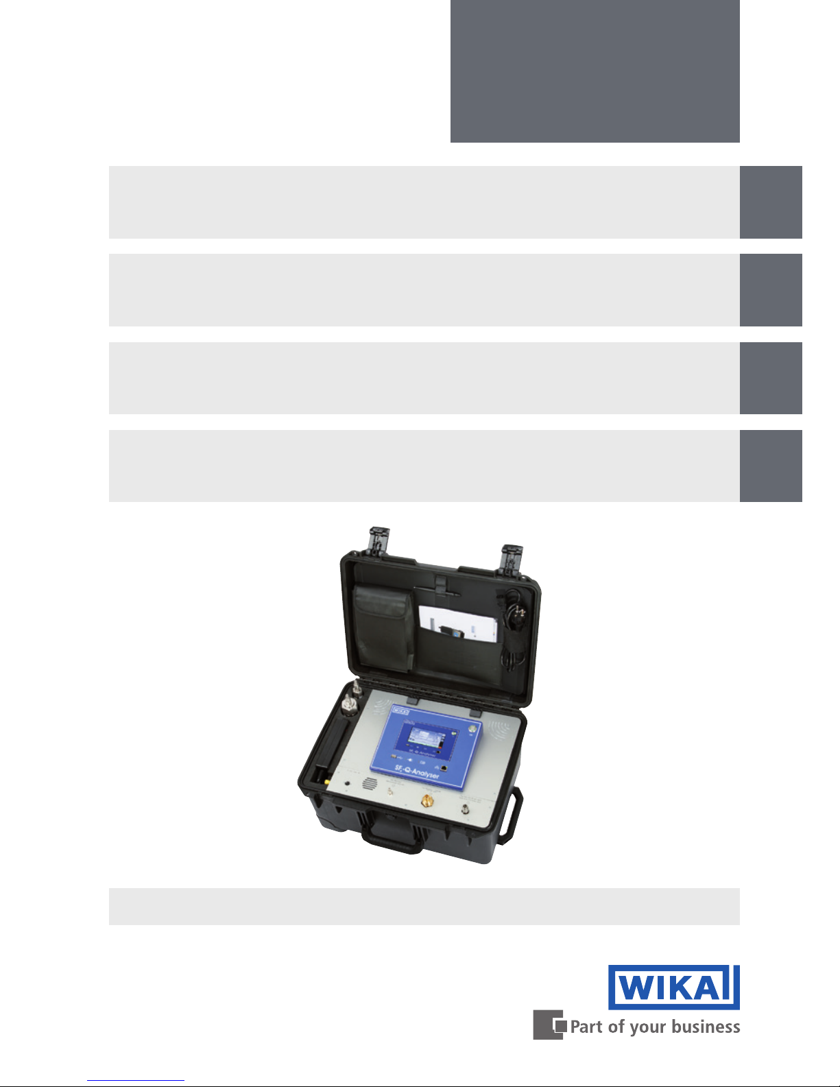
Analysegerät zur Ermittlung der Gasqualität
von Isoliergasen, Typ GA11
SF₆ gas or g³ gas
Analytic instrument for determining the quality
of insulated gases, model GA11
Instrument d‘analyse pour déterminer la
qualité du gaz isolants , Type GA11
Analizador para determinar la calidad del gas
aislante, modello GA11

2
14065341.02 11/2016 EN/DE/FR/ES
WIKA operating instructions analytic instrument, model GA11
EN
DE
FR
ES
© 09/2016 WIKA Alexander Wiegand SE & Co. KG
All rights reserved. / Alle Rechte vorbehalten.
WIKA
®
is a registered trademark in various countries.
WIKA
®
ist eine geschützte Marke in verschiedenen Ländern.
Prior to starting any work, read the operating instructions!
Keep for later use!
Vor Beginn aller Arbeiten Betriebsanleitung lesen!
Zum späteren Gebrauch aufbewahren!
Lire le mode d'emploi avant de commencer toute opération !
A conserver pour une utilisation ultérieure !
¡Leer el manual de instrucciones antes de comenzar cualquier trabajo!
¡Guardar el manual para una eventual consulta!
Betriebsanleitung Typ GA11 Seite
39 - 74
Operating instructions model GA11 Page
3 - 38
Mode d‘emploi type GA11 Page
75 - 110
Manual de instrucciones modello GA11 Página
111 - 147

3
WIKA operating instructions analytic instrument, model GA11
EN
14065341.02 11/2016 EN/DE/FR/ES
Contents
1. General information...............................................5
2. Design and function ..............................................6
2.1 Overview.......................................................6
2.2 Description .....................................................7
2.3 Scope of delivery ................................................8
3. Safety ..........................................................8
3.1 Intended use....................................................9
3.2 Personnel qualication...........................................10
3.3 Personal protective equipment ....................................10
3.4 Handling of insulating gases and gas mixtures .......................11
3.5 Valid standards and guidelines ....................................12
3.6 Dealing with pressure-retaining components.........................13
3.7 Residual risks..................................................13
3.8 Labelling, safety marks ..........................................13
4. Transport, packaging and storage .................................14
5. Commissioning, operation ........................................15
5.1 Battery / mains operated .........................................15
5.2 Connecting the gas compartment..................................15
5.3 Switching on and o.............................................16
5.4 Performing measurements .......................................17
5.5 Cancelling an ongoing measurement...............................19
5.6 Emptying depot and depressurised gas compartment .................20
5.7 Saving the measuring result ......................................21
5.8 Managing the saved measuring results .............................21
Contents

4
WIKA operating instructions analytic instrument, model GA11
EN
14065341.02 11/2016 EN/DE/FR/ES
Contents
6. Settings........................................................23
6.1 Calling the settings mode ........................................23
6.2 Settings.......................................................23
6.3 System .......................................................24
6.4 Importing/exporting the list of measurement names via USB interface ....24
6.5 Limit values for gases ...........................................25
6.6 Firmware upgrade ..............................................26
7. Software Q-Analyser Measurement Viewer ..........................27
8. Maintenance and cleaning ........................................28
8.1 Maintenance...................................................28
8.2 Cleaning ......................................................28
8.3 Recalibration ..................................................28
9. Replacing sensors...............................................29
10. Faults..........................................................31
11. Dismounting, return and disposal..................................33
12. Specications ..................................................34
13. Accessories ....................................................37
Declarations of conformity can be found online at www.wika.com

5
WIKA operating instructions analytic instrument, model GA11
EN
14065341.02 11/2016 EN/DE/FR/ES
1. General information
1. General information
■
The analytic instrument described in the operating instructions has been designed
and manufactured using state-of-the-art technology.
All components are subject to stringent quality and environmental criteria during
production. Our management systems are certied to ISO 9001 and ISO 14001.
■
These operating instructions contain important information on handling the instrument. Working safely requires that all safety instructions and work instructions are
observed.
■
Observe the relevant local accident prevention regulations and general safety regulations for the instrument’s range of use.
■
The operating instructions are part of the product and must be kept in the immediate
vicinity of the instrument and readily accessible to skilled personnel at any time.
■
Skilled personnel must have carefully read and understood the operating instructions
prior to beginning any work.
■
The manufacturer's liability is void in the case of any damage caused by using the
product contrary to its intended use, non-compliance with these operating instructions, assignment of insuciently qualied skilled personnel or unauthorised modications to the instrument.
■
The general terms and conditions contained in the sales documentation shall apply.
■
Subject to technical modications.
■
Factory calibrations/DKD/DAkkS calibrations are carried out in accordance with
international standards.
■
Further information:
- Internet address: www.wika.com/sf6
- Relevant data sheet: SP 62.11
- Application consultant:
Tel.: +49 9372 132-8971
sf6-sales@wika.com
6
WIKA operating instructions analytic instrument, model GA11
EN
14065341.02 11/2016 EN/DE/FR/ES
2. Design and function
2. Design and function
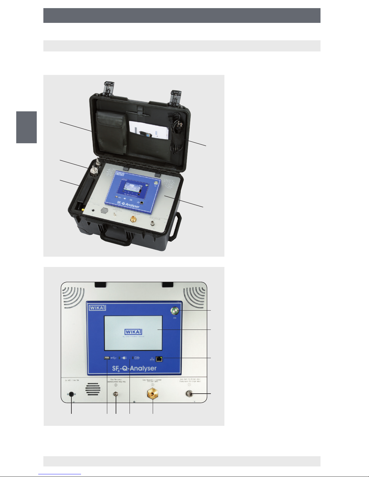
2.1 Overview
Power supply unit
Adapter
Storage for hoses
Storage for power cord
User interface
ON/OFF key
Touchscreen
Network connection (LAN)
Inlet, return pumps
Outlet, gas cylinder
Power and charging
indicators
Outlet for gas recovery bag
USB interface
Power connection

7
WIKA operating instructions analytic instrument, model GA11
EN
14065341.02 11/2016 EN/DE/FR/ES
2. Design and function
2.2 Description
Data processing and data storage
The analytic instrument model GA11 is a multi-sensor system for examining the quality
of SF₆ gas and g³ gas, e.g. in switchgear. The basic instrument consists of a built-in
computer with touchscreen for processing and storage of up to 500 data records. The
data records can be exported via the integrated USB interface.
The accompanying software “Q-Analyser Measurement Viewer” enables you to display
the data on a PC or print the measurement reports (only for SF₆-Q-Analyser).
Extendable sensor system (only for SF₆-Q-Analyser)
The sensor system of GA11 is module-based and can be extended to up to 7 sensors.
In addition, there is the possibility of storing measuring gas internally as well as pumping
it back into the original gas compartment without losses after the measurement.
Automatic adjustment of the gas quality
After the measurement, the results will be compared with customer-specically adjustable limit values according to e.g. CIGRE B3.02.01 or IEC 60480 standards. The operator
thus obtains a reliable statement on whether the insulating gas is suitable for the given
application or not, or whether it is necessary to perform a gas processing or a gas
exchange.
There are no
standards
to compare with for g³ gas.
The operator can enter his own limit
values for quality.
Battery life
If the lithium-ion accumulator is fully charged, the analytic instrument can perform at least
5 measurements with the “back pumping” function. The number of the battery-powered
pump-back cycles is largely dependent on the tank pressure of the gas to be measured.
The GA11 sends a warning message on the display when battery is low.
If the instrument is not connected to the mains in time, it will shut down automatically in
order to prevent damages and data loss. In the mains operation, the battery is charged
and the instrument can be switched on again at the same time and operate without
restrictions.
Power and charging indicators
The front control panel has two LEDs which indicate the charging status (red) or mains
operation (green).
If an error occurs during the charge cycle, the charging indicator ashes (red).
8
WIKA operating instructions analytic instrument, model GA11
EN
14065341.02 11/2016 EN/DE/FR/ES
2. Design and function / 3. Safety
2.3 Scope of delivery
■
Analytic instrument model GA11 in a sturdy transport case
■
Power supply unit with power cord
■
Calibration certicate
■
Touchpen
■
USB stick
■
Operating instructions
■
See delivery note for optionally ordered sensor system and accessories.
Cross-check scope of delivery with delivery note.
3. Safety
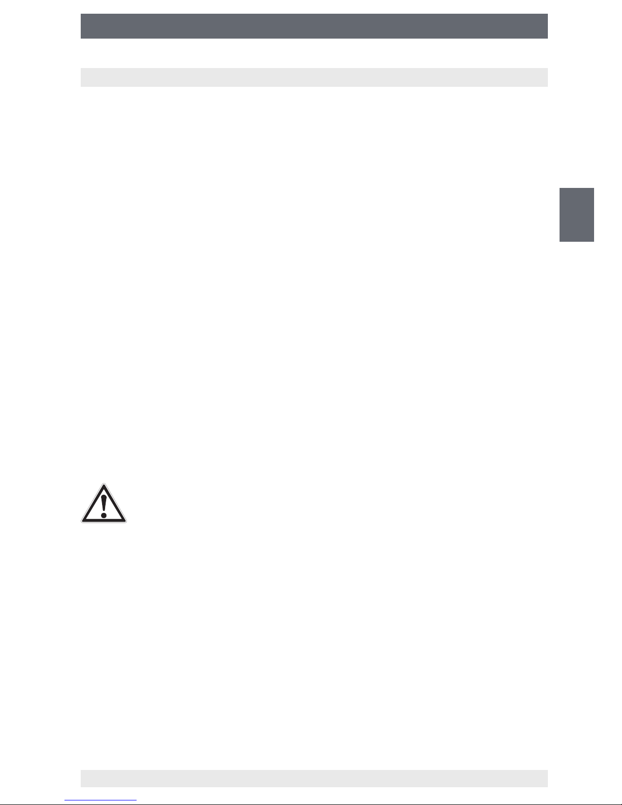
Explanation of symbols
WARNING!
... indicates a potentially dangerous situation that can result in serious injury
or death, if not avoided.
CAUTION!
... indicates a potentially dangerous situation that can result in light injuries
or damage to equipment or the environment, if not avoided.
Information
... points out useful tips, recommendations and information for ecient and
trouble-free operation.

9
WIKA operating instructions analytic instrument, model GA11
EN
14065341.02 11/2016 EN/DE/FR/ES
3. Safety
3.1 Intended use
The analytic instrument model GA11 is available in two dierent versions:
SF
6
-Q-Analyser and g³-Q-Analyser. The GA11 is used for determining the gas quality of
the following insulating gases and gas mixtures.
Permissible insulating gases and gas mixtures for SF₆-Q-Analyser
■
SF₆ gas
■
SF₆/N₂
■
SF₆/CF₄
■
CO₂
Permissible insulating gases and gas mixtures for g³-Q-Analyser
■
g³ gas
■
CO₂
■
Novec 4710
Application areas
The instrument is especially designed for applications that full the following conditions:
■
The use is only allowed in buildings or dry surroundings.
■
Use only for commercial purposes and in industrial environment.
■
The height of the operation site should not exceed 2,000 m.
■
Ambience with max. pollution degree of 3.
■
Voltage supply of overvoltage category II.
■
Ambient temperature between 0 ... 40 °C.
■
Max. inlet pressure: 35 bar (SF₆-Q-Analyser)
■
Max. outlet pressure: 10 bar (SF₆-Q-Analyser)
■
Max. inlet pressure: 12 bar (g³-Q-Analyser)
■
Max. outlet pressure: 10 bar (g³-Q-Analyser)
The instrument has been designed and built solely for the intended use described here,
and may only be used accordingly.
Only use the instrument with original accessories from WIKA.
Refrain from unauthorised modications to the instrument.
Any use beyond or dierent to the intended use is considered as improper use.
The technical specications contained in these operating instructions must be
observed. Improper handling or operation of the instrument outside of its technical
specications requires the instrument to be taken out of service immediately and
inspected by an authorised WIKA service engineer.
10
WIKA operating instructions analytic instrument, model GA11
EN
14065341.02 11/2016 EN/DE/FR/ES
3. Safety
Handle electronic precision measuring instruments with the required care (protect from
humidity, impacts, strong magnetic elds, static electricity and extreme temperatures,
do not insert any objects into the instrument or its openings). Plugs and sockets must be
protected from contamination.
The manufacturer shall not be liable for claims of any type based on operation contrary
to the intended use.
3.2 Personnel qualication
WARNING!
Risk of injury should qualication be insucient!
Improper handling can result in considerable injury and damage to equipment.
■
The activities described in these operating instructions may only be
carried out by skilled personnel who have the qualications described
below.
■
Keep unqualied personnel away from hazardous areas.
Trained personnel
The plant operator must ensure that the handling of SF
6
gas and g³ gas is only carried
out by a qualied company or by qualied persons which have been specially trained in
accordance with IEC 61634, section 4.3.1 or IEC 60480, section 10.3.1.
Special operating conditions require further appropriate knowledge, e.g. of aggressive
media.
3.3 Personal protective equipment
The personal protective equipment is designed to protect the skilled personnel from
hazards that could impair their safety or health during work. When carrying out the
various tasks on and with the instrument, the skilled personnel must wear personal
protective equipment.
Follow the instructions displayed in the work area regarding personal protective
equipment!

11
WIKA operating instructions analytic instrument, model GA11
EN
14065341.02 11/2016 EN/DE/FR/ES
3. Safety
The requisite personal protective equipment must be provided by the operating company.
Wear safety goggles!
Safety goggles to EN 166, class 2.
They protect the eyes from ying parts during coupling or releasing of
the quick connections under pressure.
Wear protective gloves!
Protect hands from friction, abrasion, cuts or deep injuries and also from
contact with hot surfaces.
3.4 Handling of insulating gases and gas mixtures
SF
6
gas is a greenhouse gas which is listed in the Kyoto Protocol. SF6 gas must not be
released into the atmosphere, but must be collected in suitable containers.
Properties of insulating gases
■
Colourless and odourless
■
Chemically neutral
■
Inert
■
Not ammable
■
Heavier than air
■
No toxicity
■
No damage to the ozone layer
Detailed information is given in IEC 60376 and IEC 61634.
Danger of suocation caused by insulating gases and gas mixtures
High concentrations of gases and gas mixtures may lead to suocation, especially at
ground level or in lower-lying areas.

12
WIKA operating instructions analytic instrument, model GA11
EN
14065341.02 11/2016 EN/DE/FR/ES
3. Safety
Danger caused by decomposition products
Insulating gas in electrical systems may contain decomposition products generated by
electric arcs:
■
Gaseous sulphur uoride
■
Sulphur hexauoride
■
Solid and atomized metal uorides, metal suldes, metal oxides
■
Hydrogen uoride
■
Sulphur dioxide
Decomposition products can be harmful to health.
■
They can cause poisoning by inhalation, ingestion or contact with the skin.
■
They may be irritating to the eyes, the respiratory system or the skin and burn them.
■
Inhalation of large quantities may damage the lungs.
Observe the following safety instructions in order to avoid danger from insulating gas:
■
Wear personal protective equipment.
■
Read the material safety data sheet of the gas supplier.
■
With large leaks, evacuate the area quickly.
■
Ensure good ventilation.
■
Ensure the leak tightness of the equipment with a leak detector (e.g. model GIR-10).
3.5 Valid standards and guidelines
Installation, assembly, commissioning:
■
BGI 753 (SF₆ plants and equipment in Germany)
■
IEC 61634 (Handling of SF₆ gas)
■
IEC 60376 (New SF₆ gas, technical grade SF₆ gas)
■
IEC 60480 (Used SF₆ gas)
■
CIGRE report 276, 2005 (Practial SF₆ gas handling instructions)
Leaks during operation:
■
IEC 60376 (New SF₆ gas, technical grade SF₆ gas)
■
IEC 60480 (Used SF₆ gas)
■
CIGRE 2002 (“SF₆ gas in the electrical industry”)
Repair work and maintenance:
■
IEC 61634 (Use and handling of SF₆ gas in high-voltage switchgear and controlgear)
■
CIGRE 1991 (Handling of SF₆ gas)
■
CIGRE report 276, 2005 (Practical SF₆ gas handling instructions)
■
CIGRE report 163, 2000 (Guide for SF₆ gas mixtures)
Insulating gas is a colourless and odourless, chemically neutral, inert and
non-inammable gas which is heavier than air, not toxic and not harmful to
the ozone layer. Detailed information is given in IEC 60376 and IEC 61634.
13
WIKA operating instructions analytic instrument, model GA11
EN
14065341.02 11/2016 EN/DE/FR/ES
3. Safety
3.6 Dealing with pressure-retaining components
Pneumatic energy can lead to serious injury.
With damaged individual components, highly pressurised air can escape and cause eye
injuries, for example.
Pressure-retaining components (e.g. adapters, hoses and external containers) may
explode due to overpressure.
Observe the following safety instructions in order to avoid danger from pneumatic
energy:
■
Depressurise the instrument before starting any work on it. Be careful of the accumulator, and ensure it is fully discharged.
■
Do not alter the pressure settings above the maximum permissible levels.
■
Make sure that all pressure-retaining components are designed for the quoted
nominal pressures (→ see chapter 12 “Specications”).
3.7 Residual risks
Despite compliance with all relevant safety regulations for the design and construction
of our instruments as well as intended use of them by the operator, residual risks may
occur during operation.
Residual risks are described in detail in the individual chapters. It is vital that you comply
with all safety instructions.
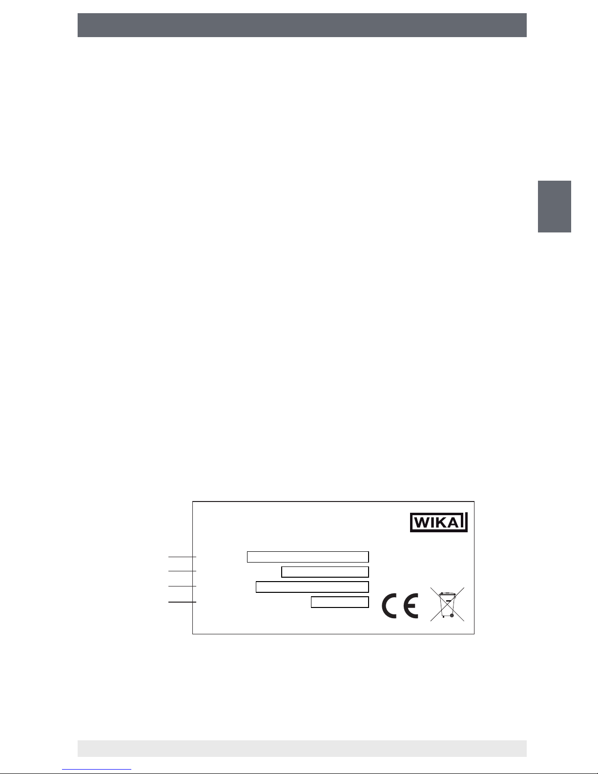
3.8 Labelling, safety marks
Product label (example)
The product label is located at the rear of the display frame.
Product designation (model)
Power supply
Serial no.
Date of manufacture
WIKA
Alexander Wiegand SE & Co. KG, 63911 Klingenberg, Germany
Product:
Power Supply:
Serial No:
Manufacturing Year:
Made in Germany

14
WIKA operating instructions analytic instrument, model GA11
EN
14065341.02 11/2016 EN/DE/FR/ES
4. Transport, packaging and storage
4. Transport, packaging and storage
4.1 Transport
Check the analytic instrument for any damage that may have been caused by transport.
Obvious damage must be reported immediately.
4.2 Packaging
Do not remove packaging until just before mounting.
Keep the packaging as it will provide optimum protection during transport (e.g. calibration,
sending for repair).
4.3 Storage
Permissible conditions at the place of storage:
Storage temperature: 0 ... 40 °C
Avoid exposure to the following factors:
■
Direct sunlight or proximity to hot objects
■
Mechanical vibration, mechanical shock (putting it down hard)
■
Soot, vapour, dust and corrosive gases
■
Hazardous environments, ammable atmospheres
■
Storage outdoors or in humid environment
■
Unauthorized access
15
WIKA operating instructions analytic instrument, model GA11
EN
14065341.02 11/2016 EN/DE/FR/ES
5. Commissioning, operation
5. Commissioning, operation
Depending on the version of the analytic instrument, the user interface may dier from
those illustrated in these operating instructions. However, the procedure is always the
same.
5.1 Battery / mains operated
The analytic instrument can be operated in battery mode and in the mains supply.
If the lithium-ion accumulator is fully charged, the analytic instrument can perform at least
5 measurements with the “back pumping” function. The number of the battery-powered
pump-back cycles is largely dependent on the tank pressure of the gas to be measured.
The GA11 sends a warning message on the display when battery is low.
If the instrument is not connected to the mains in time, it will shut down automatically in
order to prevent damages and data loss. In the mains operation, the battery is charged
and the instrument can be switched on again at the same time and operate without
restrictions.
Establishing connection to mains supply
1. Connect power supply unit to the power cord.
2.
Connect power supply unit to mains connection on the operating panel.
3.
Connect the power cord to the socket.
⇒
Connection to mains supply is established.
5.2 Connecting the gas compartment
CAUTION!
Escaping SF₆ gas results in environmental hazards!
If there are leakages at the connecting elements, the environmentally
hazardous SF₆ gas may be released to the atmosphere.
▶
Make sure that there is no leakage at any connections (e.g. by using gas
detector GIR-10).
To perform a measurement, the pressure of the gas compartment to be measured has
to be at least 1.3 bar abs. If the inlet pressure is below 1.3 bar abs., it is possible to use
an inlet pressure control unit (e.g. model GA05) to raise the pressure.
5.2.1 Pumping back in the measured gas compartment
▶
Connect “Inlet, return pumps ” to the gas compartment.
⇒
The gas compartment is connected.
During back pumping, the gas is pumped back into the gas compartment via the “Inlet,
return pumps ”.
16
WIKA operating instructions analytic instrument, model GA11
EN
14065341.02 11/2016 EN/DE/FR/ES
5. Commissioning, operation
5.2.2 Back pumping in external gas compartment (pressurised)
Requirement:
The lling pressure of the external gas compartment is between 1.3 ... 10 bar abs.
(SF₆-Q-Analyser)
The lling pressure of the external gas compartment is between 1.3 ... 12 bar abs.
(g³-Q-Analyser)
1.
Connect “Inlet, return pumps ” to the gas compartment to be measured.
2.
Connect “Outlet for gas cylinder ” to the external gas compartment.
⇒
The gas compartment is connected.
5.2.3 Back pumping in external gas compartment (depressurised)
1.
Connect “Inlet, return pumps ” to the gas compartment to be measured.
2.
Connect “Outlet for gas recovery bag ” to the external gas compartment.
⇒
The gas compartment is connected.
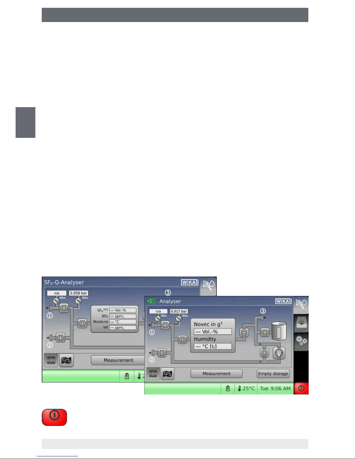
5.3 Switching on and o
Switching on
▶
Press On/Off switch.
⇒
A self-test is performed.
⇒
The residual gas is filtered.
⇒
The instrument is ready for operation.
⇒
Start screen with sensor values is displayed (the actual display may vary from the
example).
Switching o
▶
Press the following button.
▶
17
WIKA operating instructions analytic instrument, model GA11
EN
14065341.02 11/2016 EN/DE/FR/ES
5. Commissioning, operation
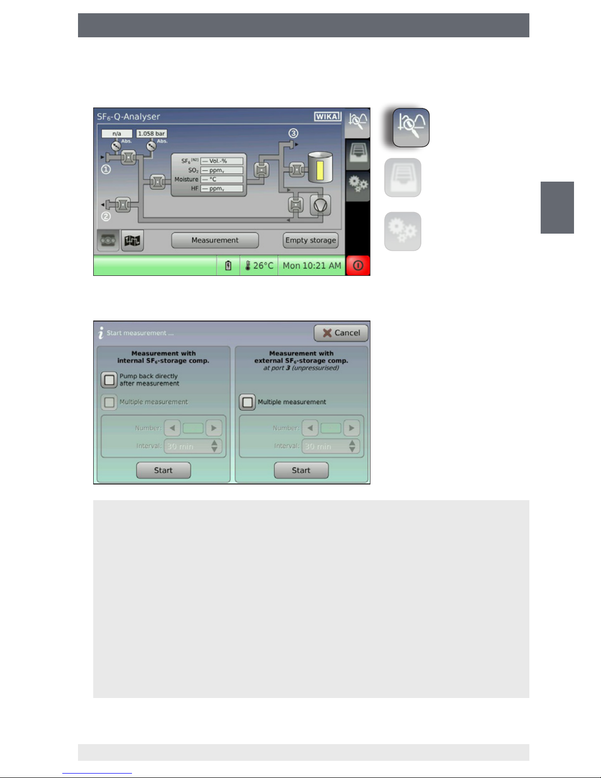
5.4 Performing measurements
1. Press “Measurement”.
2. Congure the measuring methods and press “Start” to conrm.
⇒
The measurement begins.
Measurement with internal depot
The measuring gas will be stored temporarily in the internal depot and later be pumped back
into the gas compartment to be measured or a pressurised external gas compartment.
Measurement with external container (depressurised)
The measuring gas will be directly pumped into a depressurised external gas compartment
(e.g. gas recovery bag, model GA45).
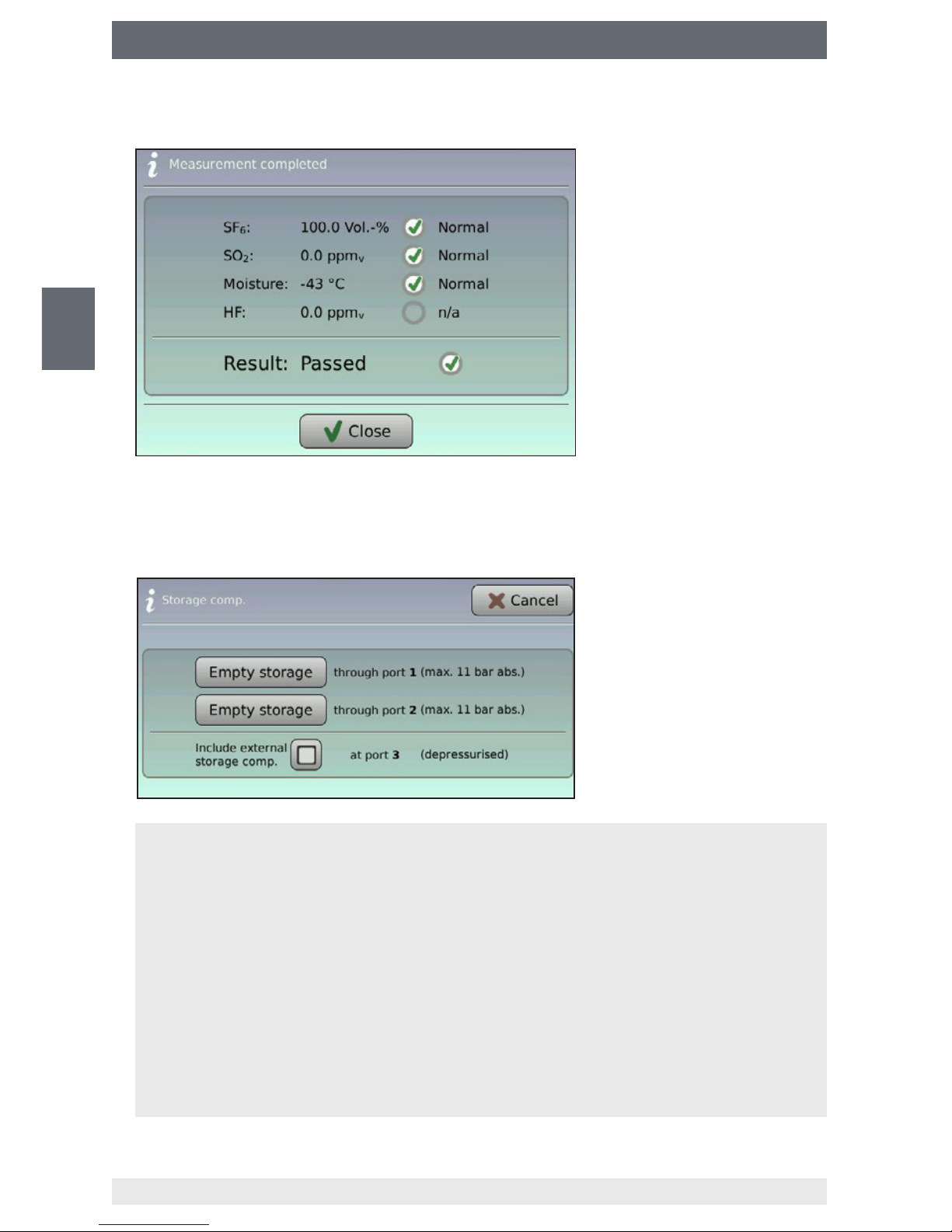
Back pumping after the measurement
Once the measurement is nished, a selection window will open, which enables the selection of the storage location.
Multiple measurement
The multiple measurement makes it possible to perform the gas quality check at specic
intervals automatically.
Measurement
Data management
Settings
18
WIKA operating instructions analytic instrument, model GA11
EN
14065341.02 11/2016 EN/DE/FR/ES
5. Commissioning, operation
3. Save or skip the measuring result.
4. Select the gas compartment for back pumping the measuring gas (only available
when the “back pumping” function is selected).
⇒
Measuring gas is pumped back.
⇒
Measurement is finished.
Connection
The measuring gas is directly pumped back into the measured gas compartment.
Connection
The measuring gas is pumped into a pressurised external gas compartment (e.g. gas cylinder).
The maximal pumping capacity of the analytic instrument is:
■
10 bar abs. (SF₆-Q-Analyser)
■
12 bar abs. (g³-Q-Analyser)
External container
With the function activated, the measuring gas is emptied from an external container at
connection as well.
19
WIKA operating instructions analytic instrument, model GA11
EN
14065341.02 11/2016 EN/DE/FR/ES
5. Commissioning, operation
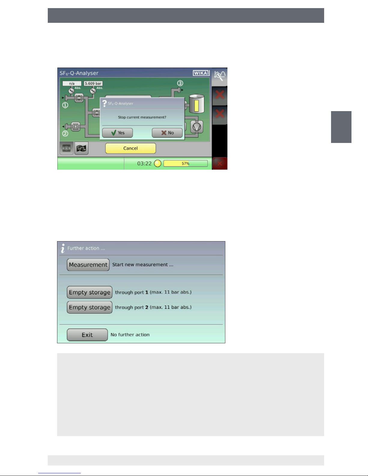
5.5 Cancelling an ongoing measurement
1. Press “Cancel” and conrm by pressing “Yes”.
2. Select the gas compartment for back pumping the measuring gas (only available
when the “back pumping” function is selected).
⇒
Measuring gas is pumped back.
⇒
Measurement is finished.
Connection
The measuring gas is directly pumped back into the measured gas compartment.
Connection
The measuring gas is pumped into a pressurised external gas compartment (e.g. gas cylinder).
The maximal pumping capacity of the analytic instrument is:
■
10 bar abs. (SF₆-Q-Analyser)
■
12 bar abs. (g³-Q-Analyser)
20
WIKA operating instructions analytic instrument, model GA11
EN
14065341.02 11/2016 EN/DE/FR/ES
5. Commissioning, operation
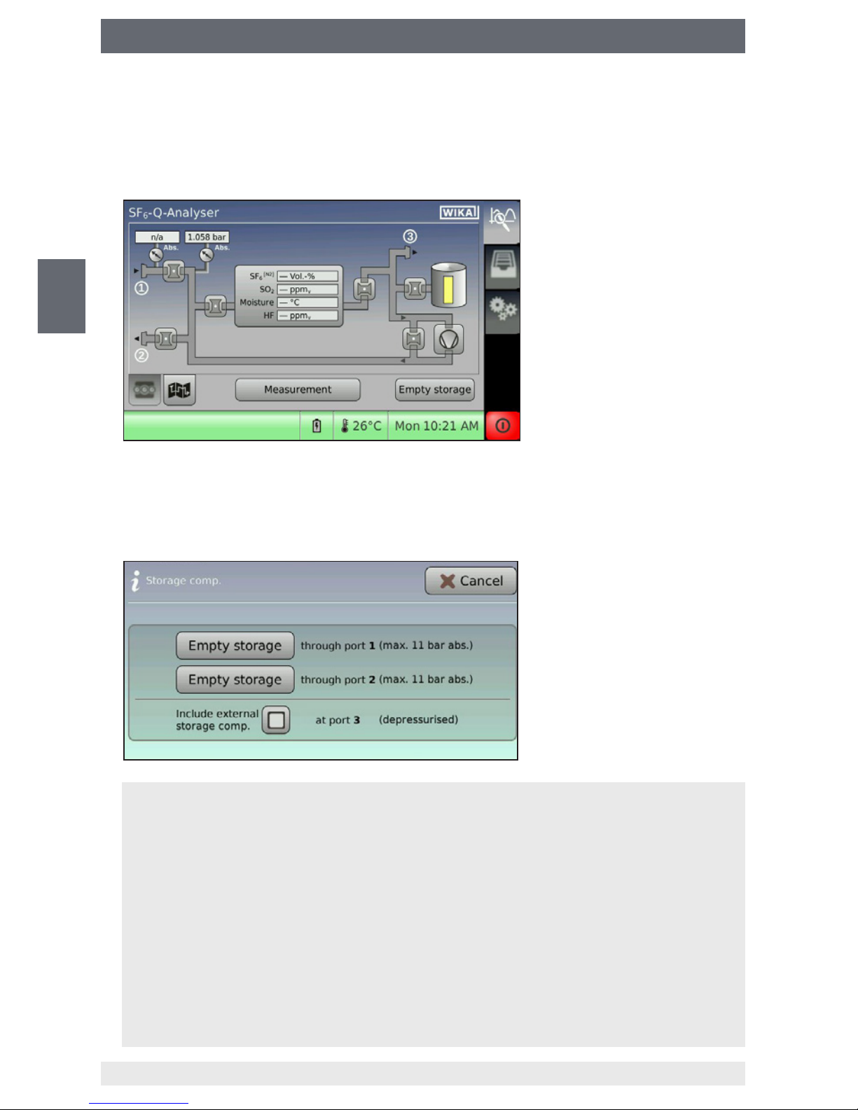
5.6 Emptying depot and depressurised gas compartment
The depot can be emptied only when there is measuring gas inside. If the depot is
already empty, the procedure is cancelled with an error message.
1. Press “Empty depot”.
2. Select the gas compartment for back pumping the measuring gas (only available
when the “back pumping” function is selected).
⇒
Measuring gas is pumped back.
⇒
Measurement is finished.
Connection
The measuring gas is directly pumped back into the measured gas compartment.
Connection
The measuring gas is pumped into a pressurised external gas compartment (e.g. gas cylinder).
The maximal pumping capacity of the analytic instrument is:
■
10 bar abs. (SF₆-Q-Analyser)
■
12 bar abs. (g³-Q-Analyser)
External container
With the function activated, the measuring gas is emptied from an external container at
connection as well.
21
WIKA operating instructions analytic instrument, model GA11
EN
14065341.02 11/2016 EN/DE/FR/ES
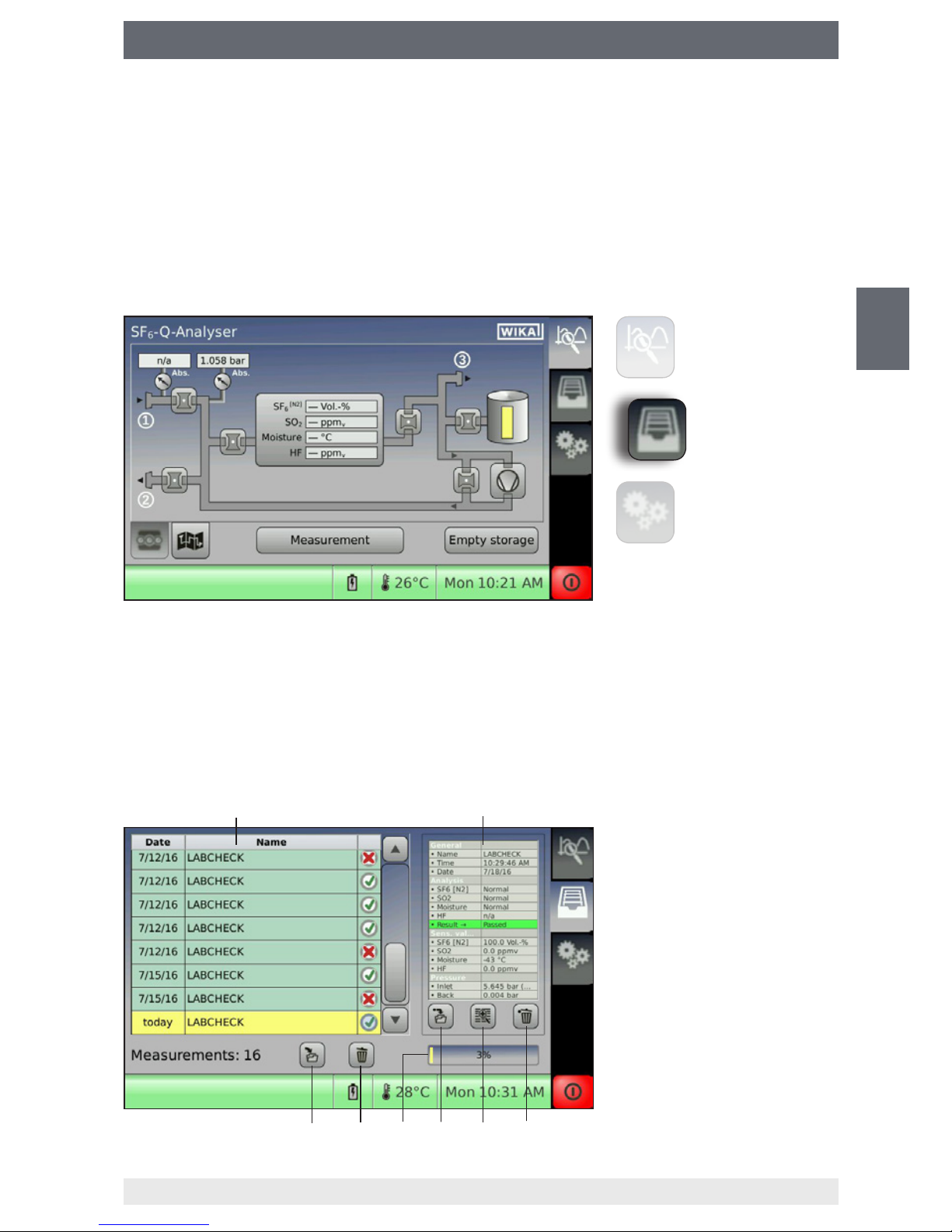
5. Commissioning, operation
Data record list
Detail window of the selected
data record
Deletes the selected data
record
Opens the data record details
in a magnied window
Saves the selected data
record on the USB data carrier
Memory utilization in %
Delete all data records
Save all data records to the
USB data carrier
5.7 Saving the measuring result
The easiest way is to use the name allocation in advance on a PC. You can create a
name list (separated by commas) and load it into the analytic instrument via the USB
interface (see chapter 6.4 “Importing/exporting the list of measurement names via USB
interface”).
5.8 Managing the saved measuring results
The main menu “Data management” must be enabled in order to access the data
management of the analytic instrument.
5.8.1 Internal memory
The internal memory can save up to 500 data records.
Depending on system setting, when the memory limit is reached, the instrument will
either send an error message or automatically overwrite the oldest data records without
warning (see chapter 6.4 “Importing/exporting the list of measurement names via USB
interface”). The data records deposited in the internal memory can be transmitted to a
USB data carrier.
Measurement
Data management
Settings
22
WIKA operating instructions analytic instrument, model GA11
EN
14065341.02 11/2016 EN/DE/FR/ES
5. Commissioning, operation
Transmitting data records to the USB data carrier
1. Connect USB data carrier to the USB interface.
2.
■
Copying all data records to the USB data carrier
Press button [8].
■
Copying individual data records to the USB data carrier
Choose a data record via the touchscreen (the data record will be marked in
yellow) and press button [5].
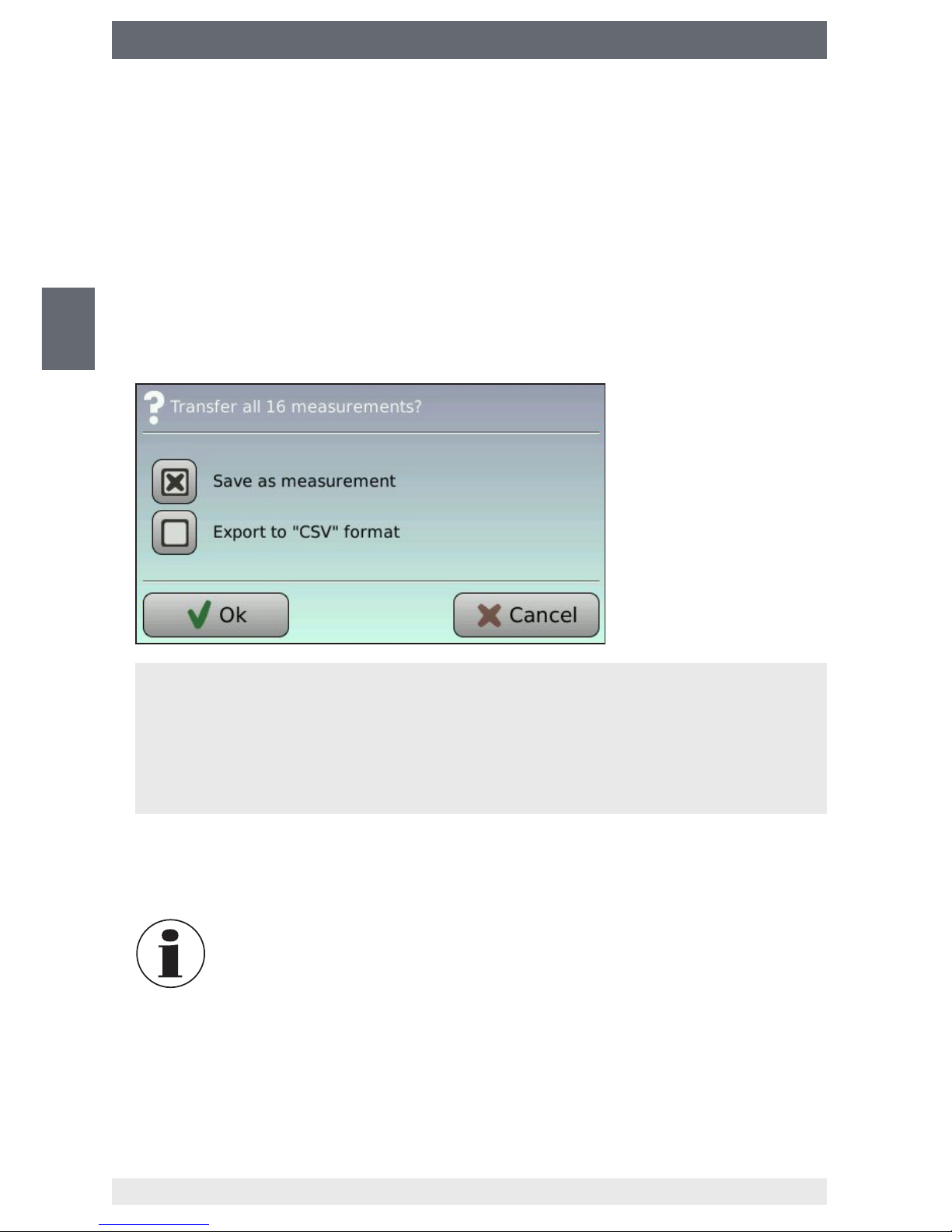
3. Select le format and conrm with “OK”.
Saving as measurement (*.mea)
The data record is saved in the analytic instrument's own format (*.mea)
Exporting in “CSV” format (*.csv)
The data record is saved in *.csv format. This format is supported by spreadsheet
programs (e.g. Microsoft Excel
®
).
4. Remove the USB data carrier once the saving process is nished (when the
hourglass symbol is extinguished).
In order to avoid data loss, only remove the USB data carrier when
the saving process is completed (when the hourglass symbol is
extinguished).
23
WIKA operating instructions analytic instrument, model GA11
EN
14065341.02 11/2016 EN/DE/FR/ES
6. Settings
6. Settings
6.1 Calling the settings mode
The main menu “Settings” must be enabled before settings to the analytic instrument
can be made.
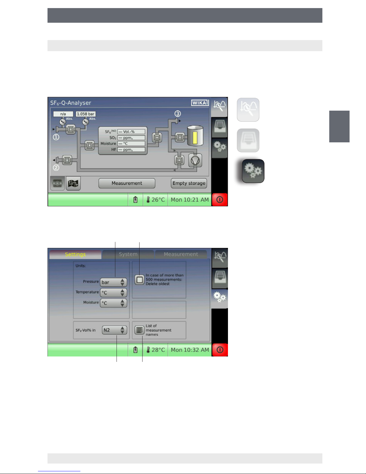
6.2 Settings
Setting the units
Activated: The oldest data records will be deleted when the limit of 500 data records is reached.
Deactivated: There will be an error message “Memory is full” when the limit of 500 data records is reached.
Importing/exporting the list of measurement names via USB interface
Calibration gas of SF6 percentage sensor
Measurement
Data management
Settings
24
WIKA operating instructions analytic instrument, model GA11
EN
14065341.02 11/2016 EN/DE/FR/ES
6. Settings
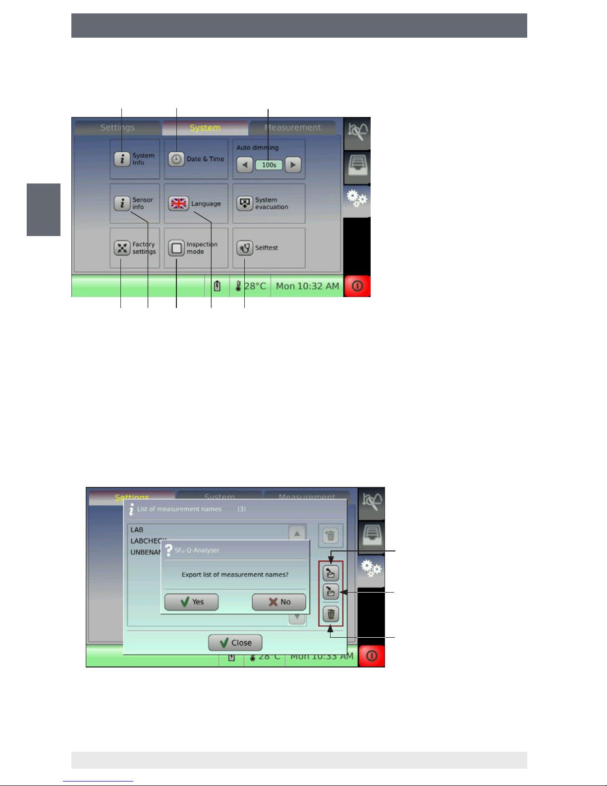
6.3 System
6.4 Importing/exporting the list of measurement names via USB interface
1. Create a list with any word processing program.
Separate measurement names with commas from each other:
Name1, Name2, Name3, ...
2. Save the list to the USB data carrier (le format is *.csv).
3. The list can be imported by clicking the icon on the analytic instrument. The imported
list will overwrite the existing list in the internal memory of the analytic instrument.
Import the list from the USB
data carrier
Export the list to the USB
data carrier
Delete the list
Information on the system
Setting date and time
After expiration of this time, the
display lighting will be dimmed
for energy saving.
Performing self-test
Changing language
The inspection mode is reserved
for WIKA service.
Information on the sensor
system
Reset to factory settings
25
WIKA operating instructions analytic instrument, model GA11
EN
14065341.02 11/2016 EN/DE/FR/ES
6. Settings
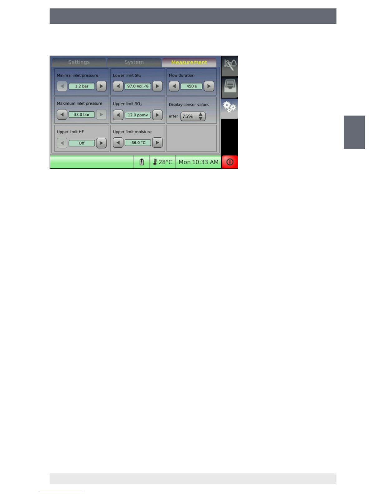
6.5 Limit values for gases
SF₆-Q-Analyser
The factory settings are the limits for the reusable SF
6
gas according to the Cigré
Recycling Guide or IEC 60480. The limits of the installed sensors can be adjusted
according to customer guidelines.
■
Lower limit of SF6: 97.0 Vol.-%
■
Upper limit of SO2: 12 ppm
v
■
Upper limit of humidity: -36.0 °C dew point
■
Flow duration: 450 seconds, ow duration = measurement duration
g³-Q-Analyser
The factory settings are preset to 0 %. There are no standards to compare with for g³
gas. The operator can enter his own limit values for quality.
Default:
■
Lower limit of g³: 3% default
■
Upper limit of humidity: -36.0 °C dew point
■
Flow duration: 450 seconds, ow duration = measurement duration

26
WIKA operating instructions analytic instrument, model GA11
EN
14065341.02 11/2016 EN/DE/FR/ES
6. Settings
6.6 Firmware upgrade
You can update the analytic instrument by upgrading the rmware.
The latest rmware can be downloaded from www.wika.de.
CAUTION!
Incomplete rmware upgrade may cause damage to the instrument!
If the power supply is terminated during the rmware installation, the instrument may be damaged.
■
Do not disconnect the analytic instrument from the mains or shut it down
during installation.
■
Ensure continuous voltage supply.
Performing upgrade
1. Download rmware from www.wika.de.
Unzip the le (*.zip) in the dened directory “UPGRADE” on the USB data carrier
(drive letter:\UPGRADE).
2. Connect USB data carrier to the switched o analytic instrument.
3. Connect the analytic instrument to the mains (no battery operation).
4. Switch on analytic instrument.
5. Wait until the installation is nished. Do not disconnect the analytic instrument from
the mains during installation.
The following screen will appear during installation.
6. Calibrate the touchscreens. Conrm the positions of 5 cross hairs with the touchpen.
7. Disconnect the USB data carrier from the analytic instrument after the “Update
completed” message shows up.
27
WIKA operating instructions analytic instrument, model GA11
EN
14065341.02 11/2016 EN/DE/FR/ES
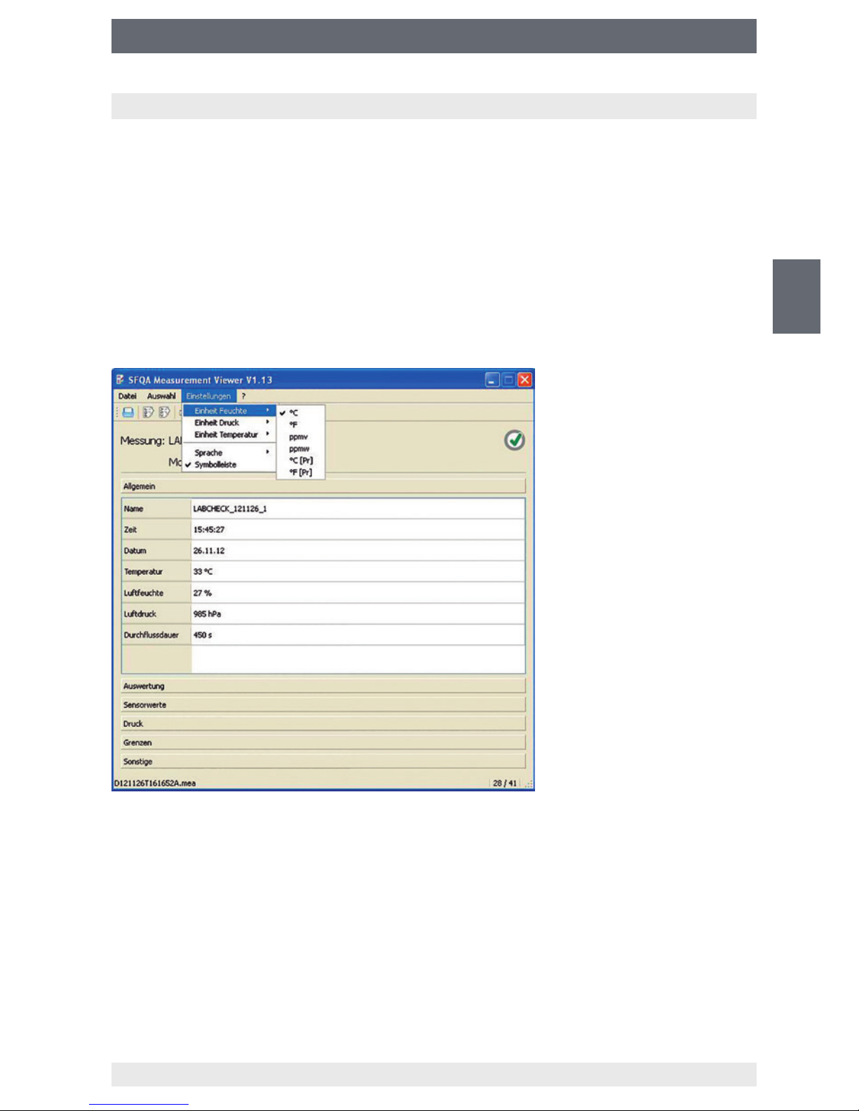
7. Software Q-Analyser Measurement Viewer
7. Software Q-Analyser Measurement Viewer
Functional description
The enclosed USB stick and the CD-ROM contain the software (only for SF₆-Q-Analyser).
System requirements:
■
Operating system: Microsoft® Windows® or Linux
This easy-to-use tool makes it possible to view the measurement les (*.mea) of the
analytic instrument, to print them out or to export them as PDF or CSV les.
The measuring results can be subsequently displayed in other units.
For the sake of clarity, the individual les are arranged in categories.
Click on the corresponding category (e.g. sensor values) to show the les.
Printing and exporting the measured data
You can generate a print report or PDF report to ensure reliable documentation and
ling of the measured data Click the respective entry or the button in the menu “File”.
It is possible to generate a CSV le from the measured data for further data evaluation,
which can be opened by spreadsheet programs.
28
WIKA operating instructions analytic instrument, model GA11
EN
14065341.02 11/2016 EN/DE/FR/ES
8. Maintenance and cleaning
8. Maintenance and cleaning
8.1 Maintenance
Repairs and maintenances must only be carried out by the manufacturer or manufacturer-approved service partners.
8.2 Cleaning
CAUTION!
■
Clean the instrument with a moist cloth.
■
Electrical connections must not come into contact with moisture.
■
Wash or clean the dismounted instrument before returning it, in order to
protect persons and the environment from exposure to residual media.
■
Residual media in the dismounted instrument can result in a risk to
persons, the environment and equipment.
Take sucient precautionary measures.
For information on returning the instrument see chapter 11.2 “Return”.
8.3 Recalibration
We recommend that the analytic instrument is regularly recalibrated by the manufacturer. In addition, every factory calibration includes a free-of-charge check of all system
parameters with respect to their compliance with the specication. The basic settings
will be corrected if necessary.
SF₆-Q-Analyser: 2 years
g³-Q-Analyser: 1 year
The time until the next recalibration for each individual sensor can be queried under
“Sensor info”.
Settings > System > Sensor info
29
WIKA operating instructions analytic instrument, model GA11
EN
14065341.02 11/2016 EN/DE/FR/ES
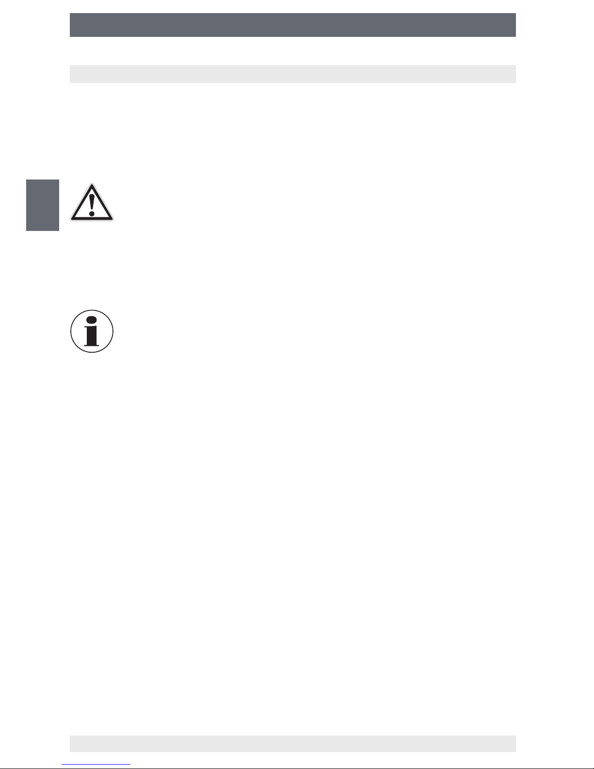
9. Replacing sensors
9. Replacing sensors
1. Switch o the analytic instrument and remove the front panel.
Remove the 4 screws of the front panel (see arrows) and fold back the front panel.
2. Pull the plug o the sensor (in this example: SO
2
sensor)
3. Screw out the sensor counterclockwise.
30
WIKA operating instructions analytic instrument, model GA11
EN
14065341.02 11/2016 EN/DE/FR/ES
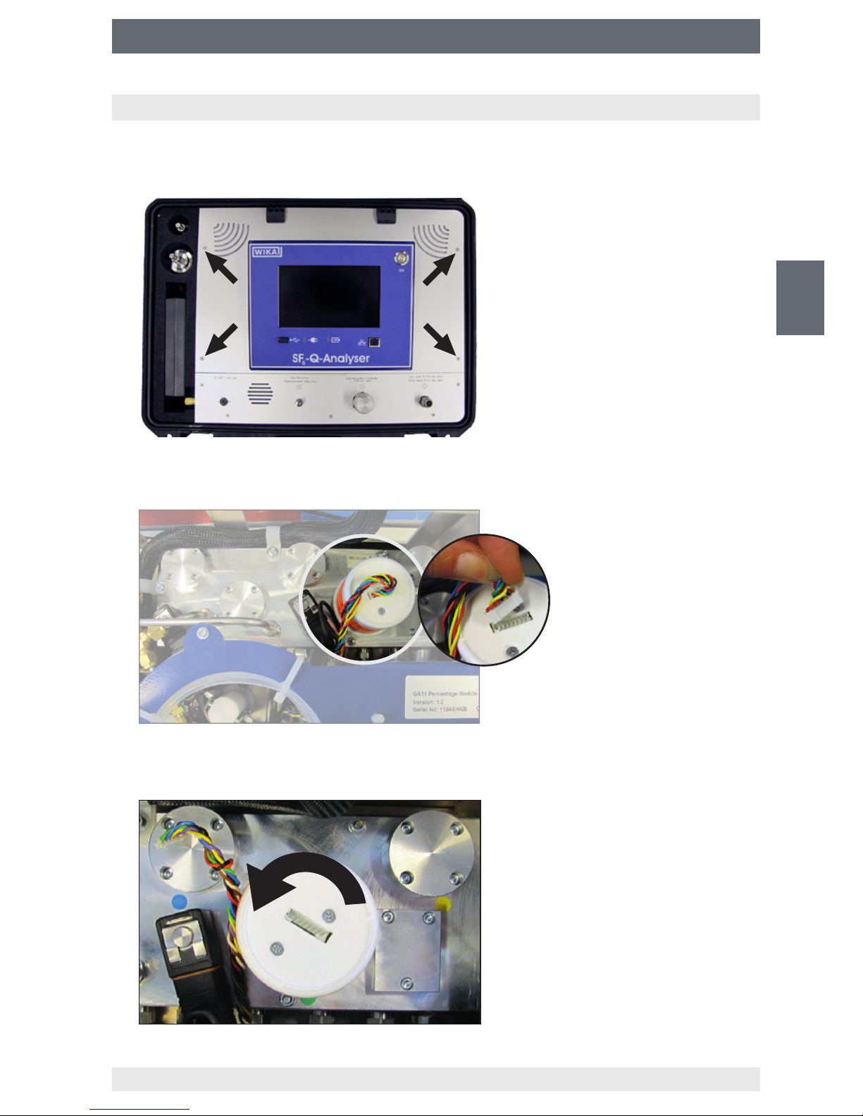
9. Replacing sensors
4. Screw in the new sensor in clockwise direction.
Screw in the sensor in a straight manner because it can easily tilt.
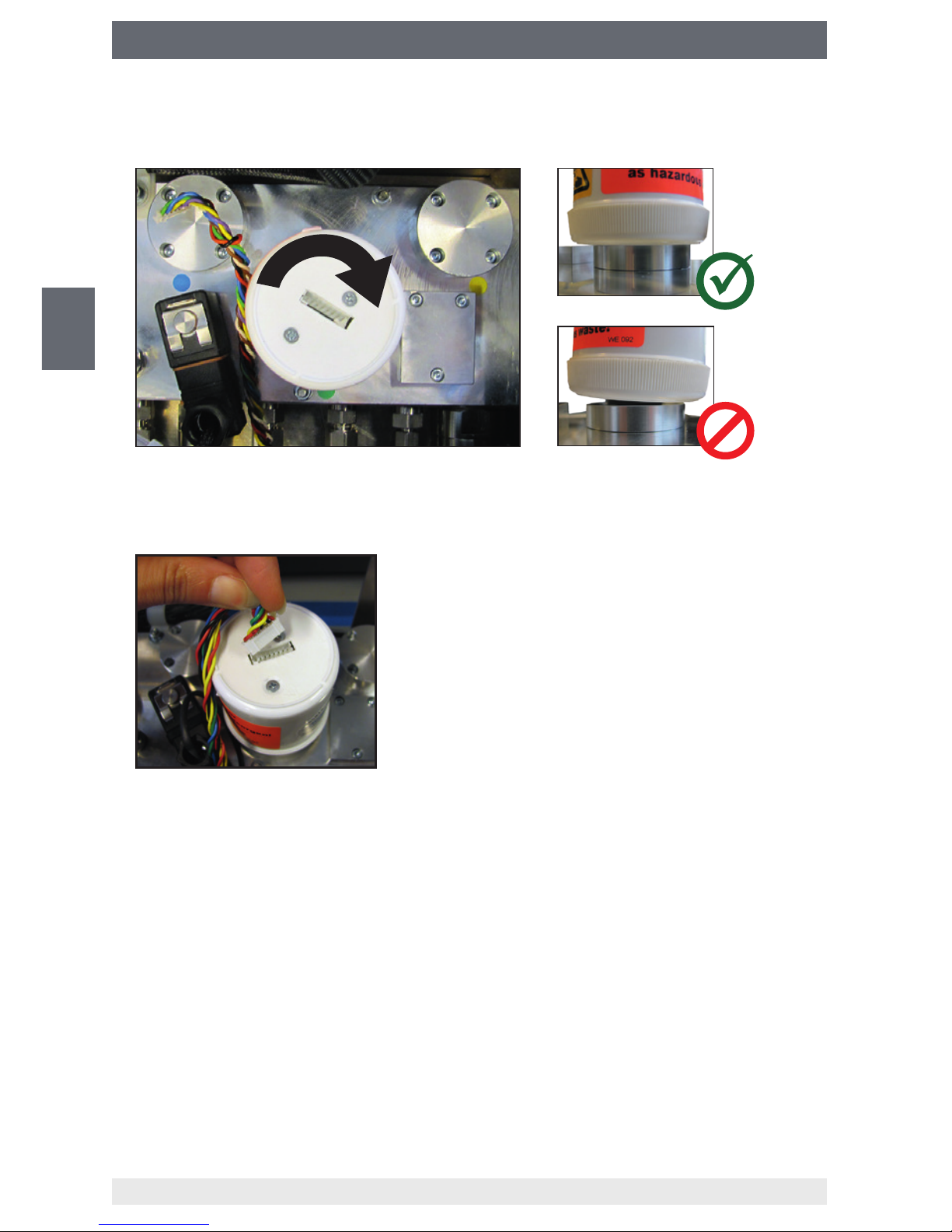
5. Connect the plug to the sensor.
The plug can only be inserted in one direction. The groove prevents the plug from
being inserted in a wrong way.
6. Reassemble the front panel and switch on the instrument (see step 1).
⇒
The sensor is recognised automatically.
7. Flood the analytic instrument with pure gas.
Perform 3 measurements with pure gas.
 Loading...