


S-11
GB
D
F
E
Operating instructions
Betriebsanleitung
Mode d'emploi
Manual de instrucciones
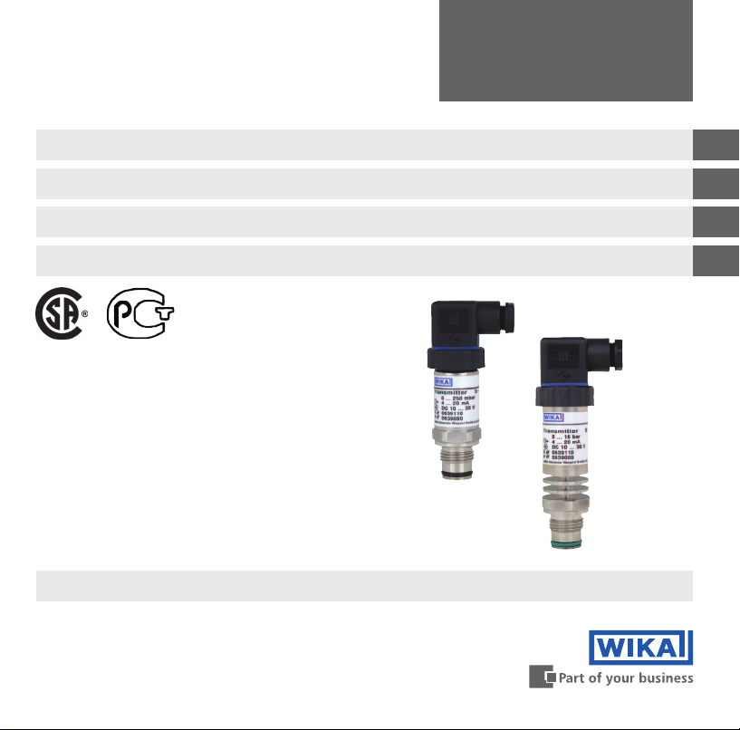
Druckmessumformer mit frontbündiger Membrane Typ S-11
Flush diaphragm pressure transmitter model S-11
Flush diaphragm pressure transmitter model S-11
Transmisor de presión con membrana aorante modelo
S-11
Transmetteur de pression à membrane aeurante type S-11

2 WIKA operating instructions
GB
D
F
E
14043046.01 06/2012 GB/D/F/E
© 2012 WIKA Alexander Wiegand SE & Co. KG
All rights reserved. / Alle Rechte vorbehalten.
WIKA
®
is a registered trademark in various countries.
WIKA
®
ist eine geschützte Marke in verschiedenen Ländern.
Prior to starting any work, read the operating instructions!
Keep for later use!
Vor Beginn aller Arbeiten Betriebsanleitung lesen!
Zum späteren Gebrauch aufbewahren!
Lire le mode d‘emploi avant de commencer toute opération !
A conserver pour une utilisation ultérieure !
¡Leer el manual de instrucciones antes de comenzar cualquier trabajo!
¡Guardar el manual para una eventual consulta posterior!
Operating instructions model S-11 Page 3 - 26
Betriebsanleitung Typ S-11 Seite 27 - 50
Mode d'emploi type S-11 Page 51 - 76
Manual de instrucciones modelo S-11 Página 77 - 99

3WIKA operating instructions pressure transmitter, model S-11
GB
14043046.01 06/2012 GB/D/F/E
1. General information 4
2. Safety 6
3. Specications 9
4. Design and function 15
5. Transport, packaging and storage 15
6. Commissioning, operation 16
7. Adjustment of zero point and span 21
8. Maintenance and cleaning 22
9. Faults 23
10. Dismounting, return and disposal 24
11. Accessories 25
12. Appendix 1: EC Declaration of conformity model S-11 26
Contents
Contents
Declarations of conformity can be found online at www.wika.com.

4 WIKA operating instructions pressure transmitter, model S-11
GB
14043046.01 06/2012 GB/D/F/E
1. General information
■
The pressure transmitter described in the operating instructions has been designed and manufac-
tured using state-of-the-art technology. All components are subject to stringent quality and
environmental criteria during production. Our management systems are certied to ISO 9001 and
ISO 14001.
■
These operating instructions contain important information on handling the instrument. Working
safely requires that all safety instructions and work instructions are observed.
■
Observe the relevant local accident prevention regulations and general safety regulations for the
instrument's range of use.
■
The operating instructions are part of the product and must be kept in the immediate vicinity of the
instrument and readily accessible to skilled personnel at any time.
■
Skilled personnel must have carefully read and understood the operating instructions, prior to begin-
ning any work.
■
The manufacturer's liability is void in the case of any damage caused by using the product contrary
to its intended use, non-compliance with these operating instructions, assignment of insuciently
qualied skilled personnel or unauthorised modications to the instrument.
■
The general terms and conditions contained in the sales documentation shall apply.
■
Subject to technical modications.
■
Further information:
- Internet address: www.wika.de / www.wika.com
- Relevant data sheet: PE 81.02
- Application consultant:
Tel.: (+49) 9372/132-8976
Fax: (+49) 9372/132-8008976
E-mail: support-tronic@wika.de
1. General information
5WIKA operating instructions pressure transmitter, model S-11
GB
14043046.01 06/2012 GB/D/F/E
Explanation of symbols
WARNING!
... indicates a potentially dangerous situation that can result in serious injury or death, if not
avoided.
CAUTION!
... indicates a potentially dangerous situation that can result in light injuries or damage to
equipment or the environment, if not avoided.
Information
… points out useful tips, recommendations and information for ecient and trouble-free
operation.
CAUTION!
... indicates a potentially dangerous situation that can result in burns, caused by hot
surfaces or liquids, if not avoided.
Abbreviations
2-wire The two connection lines are used for the voltage supply.
The measurement signal also provides the supply current.
3-wire Two connection lines are used for the power supply.
One connection line is used for the measurement signal.
U
+
Positive power supply terminal
U
-
Reference potential
S
+
Analogue output
1. General information
6 WIKA operating instructions pressure transmitter, model S-11
GB
14043046.01 06/2012 GB/D/F/E
2. Safety
WARNING!
Before installation, commissioning and operation, ensure that the appropriate pressure
transmitter has been selected in terms of measuring range, design and specic measuring
conditions.
Non-observance can result in serious injury and/or damage to equipment.
WARNING!
■
Open the connections only after the system has been depressurised.
■
Observe the working conditions in accordance with chapter 3 "Specications".
■
Always operate the pressure transmitter within the overpressure limit.
Further important safety instructions can be found in the individual chapters of these
operating instructions.
2.1 Intended use
The pressure transmitter is used to convert pressure into an electrical signal indoors and outdoors.
The instrument has been designed and built solely for the intended use described here, and may only
be used accordingly.
The technical specications contained in these operating instructions must be observed. Improper
handling or operation of the pressure transmitter outside of its technical specications requires the
instrument to be taken out of service immediately and inspected by an authorised WIKA service
engineer.
The manufacturer shall not be liable for claims of any type based on operation contrary to the intended
use.
2. Safety
7WIKA operating instructions pressure transmitter, model S-11
GB
14043046.01 06/2012 GB/D/F/E
2.2 Personnel qualication
WARNING!
Risk of injury should qualication be insucient!
Improper handling can result in considerable injury and damage to equipment.
The activities described in these operating instructions may only be carried out by skilled
personnel who have the qualications described below.
Skilled personnel
Skilled personnel are understood to be personnel who, based on their technical training, knowledge
of measurement and control technology and on their experience and knowledge of country-specic
regulations, current standards and directives, are capable of carrying out the work described and
independently recognising potential hazards.
Special operating conditions require further appropriate knowledge, e.g. of aggressive media.
2.3 Special hazards
WARNING!
For hazardous media such as oxygen, acetylene, ammable or toxic gases or liquids,
and refrigeration plants, compressors, etc., in addition to all standard regulations, the
appropriate existing codes or regulations must also be followed.
WARNING!
Residual media in the dismounted pressure transmitter can result in a risk to persons, the
environment and equipment.
Take sucient precautionary measures.
Do not use this instrument in safety or emergency stop devices. Incorrect use of the
instrument can result in injury.
Should a failure occur, aggressive media with extremely high temperature and under high
pressure or vacuum may be present at the instrument.
2. Safety

8 WIKA operating instructions pressure transmitter, model S-11
GB
14043046.01 06/2012 GB/D/F/E
2. Safety
If the serial number and the 2D code become illegible due to mechanical damage or overpainting,
traceability will no longer be possible.
Explanation of symbols
CSA, Canadian Standard Association®
The instrument was inspected and certied by CSA International. Instruments bearing this
mark comply with the applicable Canadian and US standards on safety.
GOST, Gossudarstwenny Standart (Государственный Стандарт)
GOST-R (mark)
Instruments bearing this mark comply with the applicable Russian national safety regulations
(Russian Federation).
CE, Communauté Européenne
Instruments bearing this mark comply with the relevant European directives.
2.4 Labelling / safety marks
Product label
Output signal
Pin assignment
Power supply
S# Serial no.
P# Product no.
Measuring range
2D code
Approvals

9WIKA operating instructions pressure transmitter, model S-11
GB
14043046.01 06/2012 GB/D/F/E
3. Specications
3. Specications
3.1 Measuring ranges
Relative pressure
bar Measuring range 0 ... 0.1 0 ... 0.16 0 ... 0.25 0 ... 0.4 0 ... 0.6 0 ... 1 0 ... 1.6
Overpressure limit 1 1.5 2 2 4 5 10
Burst pressure 2 2 2.4 2.4 4.8 6 12
Measuring range 0 ... 2.5 0 ... 4 0 ... 6 0 ... 10 0 ... 16 0 ... 25 0 ... 40
Overpressure limit 10 17 35 35 80 50 80
Burst pressure 12 20.5 42 42 96 96 400
Measuring range 0 ... 60 0 ... 100 0 ... 160 0 ... 250 0 ... 400 0 ... 600
Overpressure limit 120 200 320 500 800 1,200
Burst pressure 550 600 600 600 1,600 1,600
Absolute pressure
bar Measuring range 0 ... 0.25 0 ... 0.4 0 ... 0.6 0 ... 1 0 ... 1.6 0 ... 2.5 0 ... 4
Overpressure limit 2 2 4 5 10 10 17
Burst pressure 2.4 2.4 4.8 6 12 12 20.5
Measuring range 0 ... 6 0 ... 10 0 ... 16
Overpressure limit 35 35 80
Burst pressure 42 42 96
Vacuum and +/- measuring range
bar Measuring range -0.1 ... 0 -0.16 ... 0 -0.25 ... 0 -0.4 ... 0 -0.6 ... 0 -1 ... 0 -1 ... +0.6
Overpressure limit 1 1.5 2 2 4 5 10
Burst pressure 2 2 2.4 2.4 4.8 6 12
Measuring range -1 ... +1.5 -1 ... +3 -1 ... +5 -1 ... +9 -1 ... +15 -1 ... +24
Overpressure limit 10 17 35 35 80 50
Burst pressure 12 20.5 42 42 96 96

10 WIKA operating instructions pressure transmitter, model S-11
GB
14043046.01 06/2012 GB/D/F/E
Vacuum tightness
Yes
3.2 Output signals
Signal type Signal
Current (2-wire) 4 ... 20 mA
Current (3-wire) 0 ... 20 mA
Voltage (3-wire) DC 0 ... 10 V
DC 0 ... 5 V
Depending on the signal type the following loads apply:
Signal type Load in Ω
Current (2-wire) ≤ (power supply - 10 V) / 0.02 A
Current (3-wire) ≤ (power supply - 3 V) / 0.02 A
Voltage (3-wire) > maximum output signal / 1 mA
3.3 Voltage supply
Power supply
The permissible power supply depends on the corresponding output signal.
Output signal Power supply
4 ... 20 mA (2-wire) DC 10 ...30 V
0 ... 20 mA (3-wire) DC 10 ...30 V
DC 0 ... 10 V DC 14 ... 30 V
DC 0 ... 5 V DC 10 ...30 V
3. Specications

11WIKA operating instructions pressure transmitter, model S-11
GB
14043046.01 06/2012 GB/D/F/E
3. Specications
3.4 Accuracy
Accuracy at room temperature
■
Standard: ≤ ±0.5 % of span
■
Option: ≤ ±0.25 % of span
1)
1) Only for measuring ranges ≥ 0.25 bar
Including non-linearity, hysteresis, zero oset and end value deviation (corresponds to measured error
per IEC 61298-2). Calibrated in vertical mounting position with process connection facing downwards.
Non-linearity (per IEC 61298-2)
≤ ±0.2 % of span BFSL
Non-repeatability
≤ ±0.1 % of span
Temperature error in rated temperature range
Nominal temperatur: 0 ... 80 °C
Mean temperature coecient of zero point
■
≤ 0.2 % of span/10 K
■
< 0.4 % of span/10 K
1)
1) Applies to measuring ranges ≤ 0,25 bar
Mean temperature coecient of span
■
≤ 0.2 % of span/10 K
Settling time
≤ 10 ms
Long-term drift
≤ ±0.2 % of span/year

12 WIKA operating instructions pressure transmitter, model S-11
GB
14043046.01 06/2012 GB/D/F/E
Adjustability of zero point and span
1)
Adjustment is made using potentiometers inside the instrument.
Zero point ± 5 %
Span ± 5 %
1) Adjustment not possible for cable outlet with ingress protection IP 68
3.5 Operating conditions
Ingress protection (per IEC 60529)
The ingress protection depends on the type of electrical connection.
Electrical connection Ingress protection
Angular connector DIN 175301-803 A IP 65
Circular connector M12 x 1 (4-pin) IP 67
Cable outlet
■
Standard IP 67
■
Option IP 68
1)
1) Adjustability of zero point and span not possible
The stated ingress protection only applies when plugged in using mating connectors that have the
appropriate ingress protection.
Vibration resistance
■
Process connections without cooling element
20 g (IEC 60068-2-6, under resonance)
■
Process connections with cooling element
10 g (IEC 60068-2-6, under resonance)
3. Specications

13WIKA operating instructions pressure transmitter, model S-11
GB
14043046.01 06/2012 GB/D/F/E
Shock resistance
■
Process connections without cooling element
1,000 g (IEC 60068-2-27, mechanical)
■
Process connections with cooling element
400 g (IEC 60068-2-27, mechanical)
Permissible temperature ranges
Process connections without cooling element
Ambient -20 ... +80 °C
Storage -40 ... +100 °C
Medium
1)
■
Standard -30 ... +100 °C
■
Option -30 ... +125 °C
1) For measuring ranges 0 ... 400 and 0 ... 600 bar, the medium temperature is limited to -30 ... +70 °C.
2) In vertical mounting position the measuring point must be insulated in order to avoid inuences of heat radiation and convection.
3.6 Electrical connections
Short-circuit resistance
S
+
vs. U
-
Reverse polarity protection
U
+
vs. U
-
Overvoltage protection
DC 36 V
Insulation voltage
DC 500 V with NEC class 02 voltage supply (low voltage and low current max. 100 VA even under fault
conditions).
Process connections with cooling element
Ambient -20 ... +80 °C
Storage -40 ... +100 °C
Medium
1)
-20 ... +150 °C
3. Specications

14 WIKA operating instructions pressure transmitter, model S-11
GB
14043046.01 06/2012 GB/D/F/E
3.7 Process connections
Process connection Available measuring ranges
G ½ B ush
1)
0 ... 2.5 to 0 ... 600 bar
G 1 B ush
1)
0 ... 0.1 to 0 ... 1.6 bar
Hygienic G 1 B ush 0 ... 0.1 to 0 ... 25 bar
3.8 Materials
Wetted parts
■
Stainless steel
■
For sealing materials see table
Process connection Standard Option
without cooling element NBR
■
FPM/FKM
■
EPDM
with cooling element FPM/FKM EPDM
Hygienic EPDM -
Non-wetted parts
Internal system ll uid
■
Standard: Synthetic oil
■
Option: Food-compatible system ll uid per FDA 21 CFR 178.3750
3.9 Approvals, directives and certicates
Approval
■
CSA
■
GOST
3. Specications

15WIKA operating instructions pressure transmitter, model S-11
GB
14043046.01 06/2012 GB/D/F/E
CE conformity
■
EMC directive 2004/108/EC, EN 61326 emission (group 1, class B) and immunity (industrial
application)
■
Pressure equipment directive 97/23/EC
For special model numbers, e.g. S-11000, please note the specications stated on the delivery note.
For further specications see WIKA data sheet PE 81.02 and the order documentation.
4. Design and function
4.1 Description
The prevailing pressure is measured at the sensor element through the deformation of a diaphragm.
By supplying power, this deformation of the diaphragm is converted into an electrical signal. The output
signal from the pressure transmitter is amplied and standardised. The output signal is proportional to
the measured pressure.
4.2 Scope of delivery
Cross-check the scope of delivery with the delivery note.
5. Transport, packaging and storage
5.1 Transport
Check the pressure transmitter for any damage that may have been caused during transportation.
Obvious damage must be reported immediately.
5.2 Packaging
Do not remove packaging until just before mounting.
Keep the packaging as it will provide optimum protection during transport (e.g. change in installation site,
sending for repair).
3. Specications / 4. ... / 5. Transport, packaging and storage
16 WIKA operating instructions pressure transmitter, model S-11
GB
14043046.01 06/2012 GB/D/F/E
5.3 Storage
Permissible conditions at the place of storage:
■
Storage temperature: see chapter 3 “Specications”
■
Humidity: 45 ... 75 % relative humidity
Avoid exposure to the following factors:
■
Mechanical vibration, mechanical shock (putting it down hard)
■
Soot, vapour, dust and corrosive gases
■
Potentially explosive environments, ammable atmospheres
Store the pressure transmitter in its original packaging in a location that fulls the conditions listed
above. If the original packaging is not available, pack and store the instrument as described below:
1. Place the protection cap on the process connection
2. Place the instrument, along with shock-absorbent material, in the packaging.
WARNING!
Before storing the instrument (following operation), remove any residual media. This is of
particular importance if the medium is hazardous to health, e.g. caustic, toxic, carcinogenic,
radioactive, etc..
6. Commissioning, operation
CAUTION!
Prior to commissioning, the pressure transmitter must be subjected to a visual inspection.
■
Leaking uid is indicative of damage.
■
Check the diaphragm of the process connection for any damage.
■
Only use the pressure transmitter if it is in perfect condition with respect to safety.
5. Transport, packaging, ... / 6. Commissioning, operation
17WIKA operating instructions pressure transmitter, model S-11
GB
14043046.01 06/2012 GB/D/F/E
6. Commissioning, operation
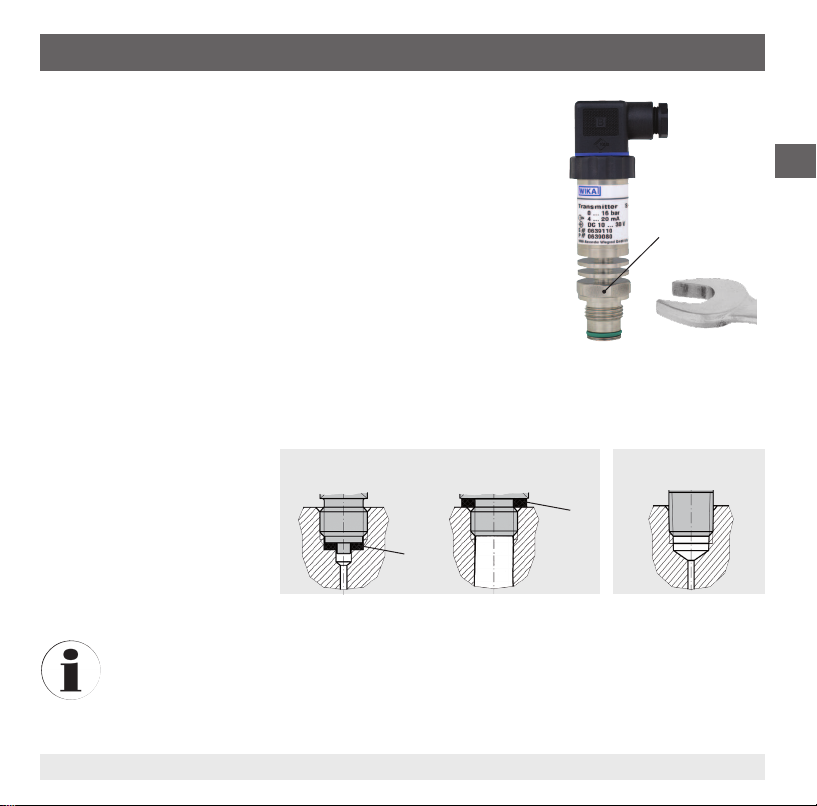
6.1 Mechanical mounting
■
Remove the protection cap not until shortly before installation.
■
Ensure that the diaphragm of the process connection is not damaged
during installation.
■
The sealing faces at the pressure transmitter and the measuring point
always have to be clean.
■
Only ever screw in, or unscrew, the instrument using the spanner
ats. Never use the case or the cooling element as a working surface.
■
The correct torque depends on the dimensions of the process
connection and the gasket used (form/material).
■
When screwing in, do not cross the threads.
■
For information on tapped holes and welding sockets, see Technical
information IN 00.14 at www.wika.com.
■
Attach the connector and screw it in hand-tight. The assembly of the
angular connector is described in chapter 6.2 "Electrical mounting".
Sealing
Correct sealing of the process
connections with parallel threads
at the sealing face
must be
made using suitable at gaskets,
sealing rings or WIKA prole
sealings. The sealing of tapered
threads (e.g. NPT threads) is
made by providing the thread with
additional sealing material such as, for example, PTFE tape (EN 837-2).
For further information on seals see WIKA data sheet AC 09.08 or under www.wika.com.
Spanner ats
Parallel thread Tapered thread
per EN 837 per DIN 3852-E
NPT, R and PT
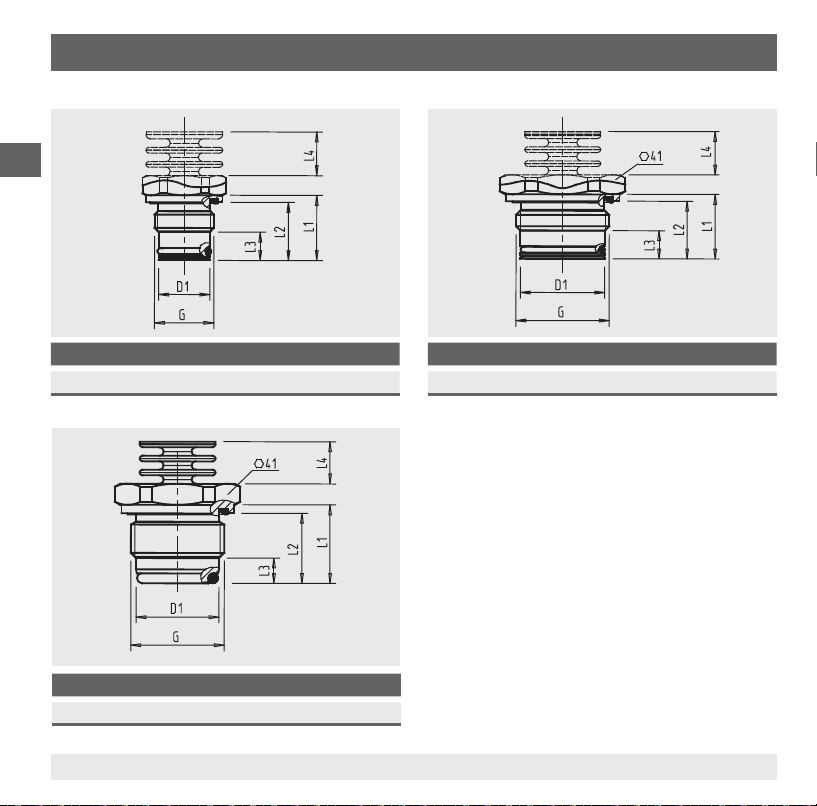
G D1 L1 L2 L3 L4
G ½ B 18 23 20.5 10 15.5
G D1 L1 L2 L3 L4
G 1 B 30 23 20.5 10 15.5
G D1 L1 L2 L3 L4
G 1 B hygienic 29.5 28 25 9 15.5
18 WIKA operating instructions pressure transmitter, model S-11
GB
14043046.01 06/2012 GB/D/F/E
For information on tapped holes and welding
sockets, see Technical information IN 00.14 at
www.wika.com.
6. Commissioning, operation
Dimensions of the process connections in mm
19WIKA operating instructions pressure transmitter, model S-11
GB
14043046.01 06/2012 GB/D/F/E
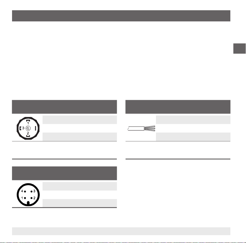
Circular connector M12 x 1 (4-pin)
2-wire 3-wire
U
+
1 1
U
-
3 3
S
+
- 4
Cable outlet, unshielded
2-wire 3-wire
U
+
brown brown
U
-
green green
S
+
- white
Wire cross-section 3 x 0.5 mm
2
Cable diameter 6.8 mm
Cable lengths 1.5 m, 3 m, 5 m, 10 m, 15 m
Angular connector DIN 175301-803 A
2-wire 3-wire
U
+
1 1
U
-
2 2
S
+
- 3
Wire cross-section max. 1.5 mm
2
Cable diameter 6 ... 8 mm
6. Commissioning, operation
6.2 Electrical mounting
■
The instrument must be earthed via the process connection.
■
For instruments with voltage output, use shielded cable, and, if the cables are longer than 30 m or
they leave the building, earth the shield at least at one end of the cable.
■
In North America, use the instrument in line with "class 2 circuits" or "class 2 power units" in accord-
ance with CEC (Canadian Electrical Code) or NEC (National Electrical Code).
■
Select a cable diameter that matches the cable gland of the plug. Make sure that the cable gland of
the mounted plug has a tight t and that the seals are present and undamaged. Tighten the threaded
connection and check that the seal is correctly seated, in order to ensure a tight seal.
■
For cable outlets, make sure that no moisture enters at the cable end.
Connection diagrams
20 WIKA operating instructions pressure transmitter, model S-11
GB
14043046.01 06/2012 GB/D/F/E
6. Commissioning, operation
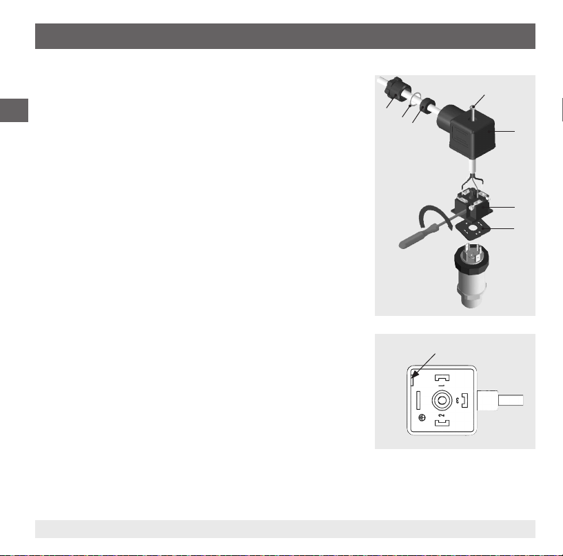
Fitting a DIN 175301-803 angular connector
1. Loosen the screw .
2. Loosen the cable gland .
3. Pull the angled socket + from the instrument.
4. Via the mounting hole , lever the terminal block out of the
case .
5. Pass the cable with the appropriate cable outer diameter (see
"Connection diagrams") through the cable gland , ring ,
sealing and the case .
6. Connect the cable ends to the connection terminals on the
terminal block in accordance with the pin assignment (see
"Connection diagrams" for the pin assignment).
7. Press the terminal block into the case .
8. 8. Tighten the cable gland around the cable. Make sure that
the cable gland and seal are not damaged and that they are
assembled correctly in order to ensure ingress protection.
9. Place the at, square gasket over the pressure transmitter's
connection pins.
10. Slide the assembled angled socket + onto the pressure
transmitter's connection pins.
11. Using the screw , screw the angled socket to the pressure
transmitter, hand-tight.
Mounting hole
21WIKA operating instructions pressure transmitter, model S-11
GB
14043046.01 06/2012 GB/D/F/E
7. Adjustment of zero point and span
7. Adjustment of zero point and span
Only adjust the span-setting potentiometer if calibration equipment is available which has at
least three times the accuracy of the pressure transmitter.
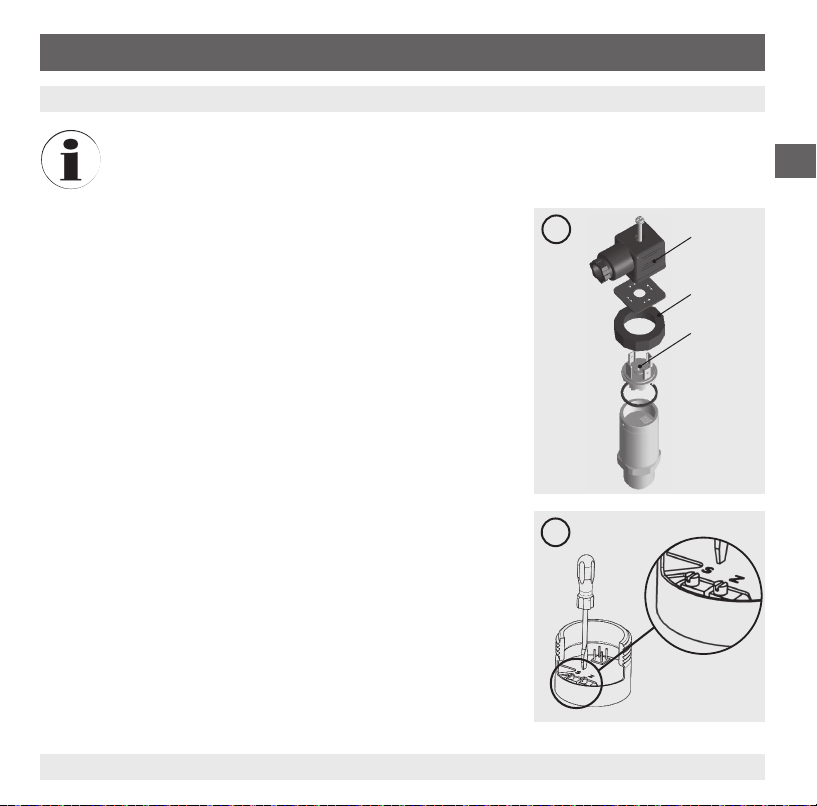
7.1 Preparation (gure A)
To gain access to the potentiometers, open the instrument as follows:
■
Disconnect the electrical connection from the instrument.
■
Remove the clamping nut .
■
Carefully pull the instrument connector from the instrument.
■
Connect the instrument connector to the power supply and a
display unit (e.g. ammeter, voltmeter) according to the connection
diagram.
7.2 Adjustment of zero point (gure B)
■
Go to the start of the measuring range.
■
Using potentiometer "Z", adjust the minimum output signal
(e.g. 4 mA)
7.3 Setting the span (gure B)
■
Go to the end of the measuring range.
■
Using potentiometer "S", adjust the maximum output signal
(e.g. 20 mA)
■
Check the zero point and if there is any deviation, re-adjust it.
■
Repeat the procedure until the zero point and the span are set
correctly.
A
B
22 WIKA operating instructions pressure transmitter, model S-11
GB
14043046.01 06/2012 GB/D/F/E
7. Adjustment of zero point ... / 8. Maintenance and cleaning
7.4 Finish the adjustment (gure A)
■
Disconnect the instrument connector from the power supply and the display unit.
■
Carefully push the instrument connector onto the instrument, without damaging the wires or the
seals. The seals must be clean and undamaged in order to guarantee the given ingress protection.
■
Tighten the clamping nut
.
After the adjustment, check that the system is functioning correctly.
Recommended recalibration cycle: 1 year
8. Maintenance and cleaning
8.1 Maintenance
This pressure transmitter is maintenance-free.
Repairs must only be carried out by the manufacturer.
8.2 Cleaning
CAUTION!
■
Before cleaning, correctly disconnect the instrument from the pressure supply, switch it
o and disconnect it from the power supply.
■
Do not use any pointed or hard objects for cleaning, as they may damage the diaphragm
of the process connection.
■
Clean the instrument with a moist cloth.
■
Electrical connections must not come into contact with moisture.
■
Wash or clean the dismounted instrument before returning it in order to protect personnel
and the environment from exposure to residual media.
■
Residual media in the dismounted pressure transmitter can result in a risk to persons,
the environment and equipment. Take sucient precautionary measures.
For information on returning the instrument see chapter 10.2 "Return".

23WIKA operating instructions pressure transmitter, model S-11
GB
14043046.01 06/2012 GB/D/F/E
Fault Possible cause Measure
No output signal Cable break
No/wrong power supply
Check the through drilling
Correct the power supply
No/wrong output signal Wiring error Rectify the wiring
Constant output signal upon
change in pressure
Mechanical overload caused by overpressure Replace instrument
Signal span too small/drops Mechanical overload caused by overpressure
Diaphragm damage
Sealing/sealing face damaged/soiled, sealing
does not have a tight t, threads jammed
Replace instrument
Replace instrument
Clean the sealing/sealing face,
replace sealing
Signal span varies/inaccurate EMC interference sources in the environment
(e.g. frequency converter)
Operating temperature too high/low
Instrument not earthed
Strongly varying pressure of the process
medium
Shield instrument; shield cable;
remove source of interference
Observe the permissible tempera-
tures
Earth the instrument
Damping; consulting by the manu-
facturer
Deviating zero point signal Operating temperature too high/low
Other mounting position
Overpressure limit exceeded
Observe the permissible tempera-
tures
Adjust the zero point
Replace instrument
9. Faults
In the event of any faults, rst check whether the pressure transmitter is mounted correctly, mechanically
and electrically.
9. Faults
24 WIKA operating instructions pressure transmitter, model S-11
GB
14043046.01 06/2012 GB/D/F/E
9. Faults / 10. Dismounting, return and disposal
CAUTION!
If faults cannot be eliminated by means of the measures listed above, the pressure
transmitter must be shut down immediately, and it must be ensured that signal is no longer
present, and it must be prevented from being inadvertently put back into service. In this
case, contact the manufacturer. If a return is needed, follow the instructions given in chapter
10.2 "Return".
10. Dismounting, return and disposal
WARNING!
Residual media in the dismounted pressure transmitter can result in a risk to persons, the
environment and equipment.
Take sucient precautionary measures.
10.1 Dismounting
WARNING!
Risk of burns!
Let the instrument cool down suciently before dismounting!
During dismounting there is a risk of dangerously hot pressure media escaping.
Only disconnect the pressure transmitter once the system has been depressurised!
During removal, do not damage the diaphragm of the process connection. After removal and cleaning
(see chapter 8.2 "Cleaning"), place the protection cap on the instrument to protect the diaphragm.
25WIKA operating instructions pressure transmitter, model S-11
GB
14043046.01 06/2012 GB/D/F/E
10.2 Return
WARNING!
Absolutely observe the following when shipping the instrument:
All instruments delivered to WIKA must be free from any kind of hazardous substances
(acids, leachate, solutions, etc.).
When returning the instrument, use the original packaging or a suitable transport package.
Enclose the completed returns form with the instrument.
The return form can be found under the heading 'Service' at www.wika.com.
10.3 Disposal
Incorrect disposal can put the environment at risk.
Dispose of instrument components and packaging materials in an environmentally compatible way and
in accordance with the country-specic waste disposal regulations.
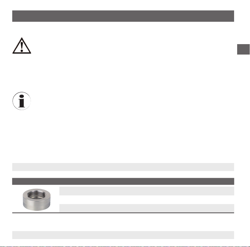
11. Accessories
Description Order no.
Welding socket for G ½ B flush 1192299
Welding socket for G 1 B flush 1192264
Welding socket for G 1 B hygienic flush 2166011
10. Dismounting, return and disposal / 11. Accessories
26 WIKA operating instructions pressure transmitter, model S-11
GB
14043046.01 06/2012 GB/D/F/E
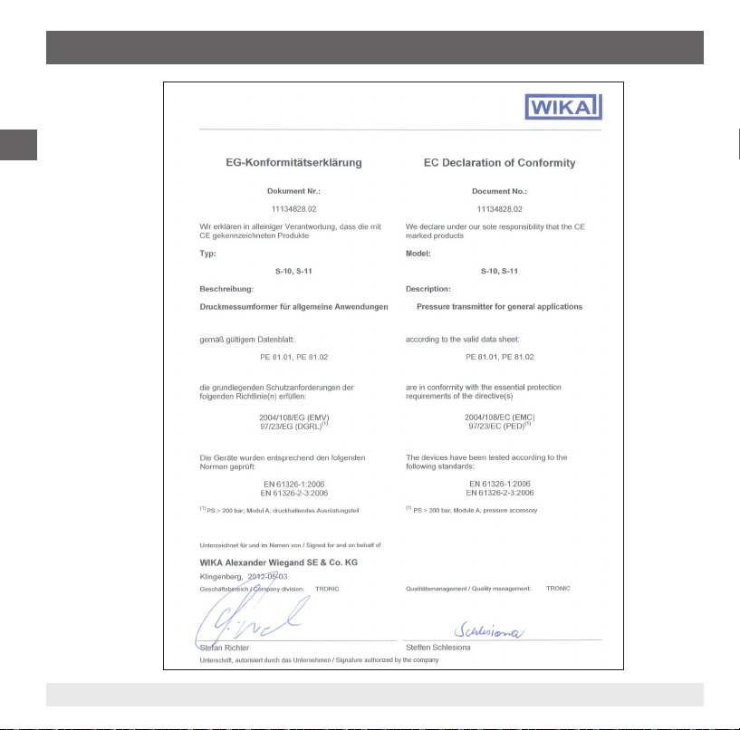
Appendix 1: EC Declaration of conformity model S-11
27WIKA Betriebsanleitung Druckmessumformer, Typ S-11
D
14043046.01 06/2012 GB/D/F/E
1. Allgemeines 28
2. Sicherheit 30
3. Technische Daten 33
4. Aufbau und Funktion 39
5. Transport, Verpackung und Lagerung 39
6. Inbetriebnahme, Betrieb 40
7. Einstellung Nullpunkt und Spanne 45
8. Wartung und Reinigung 46
9. Störungen 47
10. Demontage, Rücksendung und Entsorgung 48
11. Zubehör 49
12. Anlage 1: EG-Konformitätserklärung Typ S-11 50
Inhalt
Inhalt
Konformitätserklärungen nden Sie online unter www.wika.de.

28 WIKA Betriebsanleitung Druckmessumformer, Typ S-11
D
14043046.01 06/2012 GB/D/F/E
1. Allgemeines
■
Der in der Betriebsanleitung beschriebene Druckmessumformer wird nach den neuesten Erkenntnis-
sen konstruiert und gefertigt.
Alle Komponenten unterliegen während der Fertigung strengen Qualitäts- und Umweltkriterien.
Unsere Managementsysteme sind nach ISO 9001 und ISO 14001 zertiziert.
■
Diese Betriebsanleitung gibt wichtige Hinweise zum Umgang mit dem Gerät. Voraussetzung für
sicheres Arbeiten ist die Einhaltung aller angegebenen Sicherheitshinweise und Handlungsanwei-
sungen.
■
Die für den Einsatzbereich des Gerätes geltenden örtlichen Unfallverhütungsvorschriften und allge-
meinen Sicherheitsbestimmungen einhalten.
■
Die Betriebsanleitung ist Produktbestandteil und muss in unmittelbarer Nähe des Gerätes für das
Fachpersonal jederzeit zugänglich aufbewahrt werden.
■
Das Fachpersonal muss die Betriebsanleitung vor Beginn aller Arbeiten sorgfältig durchgelesen und
verstanden haben.
■
Die Haftung des Herstellers erlischt bei Schäden durch bestimmungswidrige Verwendung, Nichtbe-
achten dieser Betriebsanleitung, Einsatz ungenügend qualizierten Fachpersonals sowie eigen-
mächtiger Veränderung am Gerät.
■
Es gelten die allgemeinen Geschäftsbedingungen in den Verkaufsunterlagen.
■
Technische Änderungen vorbehalten.
■
Weitere Informationen:
- Internet-Adresse: www.wika.de / www.wika.com
- zugehöriges Datenblatt: PE 81.02
- Anwendungsberater:
Tel.: (+49) 9372/132-8976
Fax: (+49) 9372/132-8008976
E-Mail: support-tronic@wika.de
1. Allgemeines
29WIKA Betriebsanleitung Druckmessumformer, Typ S-11
D
14043046.01 06/2012 GB/D/F/E
Symbolerklärung
WARNUNG!
… weist auf eine möglicherweise gefährliche Situation hin, die zum Tod oder zu schweren
Verletzungen führen kann, wenn sie nicht gemieden wird.
VORSICHT!
… weist auf eine möglicherweise gefährliche Situation hin, die zu geringfügigen oder
leichten Verletzungen bzw. Sach- und Umweltschäden führen kann, wenn sie nicht
gemieden wird.
Information
… hebt nützliche Tipps und Empfehlungen sowie Informationen für einen ezienten und
störungsfreien Betrieb hervor.
VORSICHT!
… weist auf eine möglicherweise gefährliche Situation hin, die durch heiße Oberächen
oder Flüssigkeiten zu Verbrennungen führen kann, wenn sie nicht gemieden wird.
Abkürzungen
2-Leiter Die zwei Anschlussleitungen dienen zur Spannungsversorgung.
Der Speisestrom ist das Messsignal.
3-Leiter Zwei Anschlussleitungen dienen zur Spannungsversorgung.
Eine Anschlussleitung dient für das Messsignal.
U
+
Positiver Versorgungsanschluss
U
-
Bezugspotential
S
+
Analogausgang
1. Allgemeines
30 WIKA Betriebsanleitung Druckmessumformer, Typ S-11
D
14043046.01 06/2012 GB/D/F/E
2. Sicherheit
WARNUNG!
Vor Montage, Inbetriebnahme und Betrieb sicherstellen, dass der richtige Druckmessum-
former
hinsichtlich Messbereich, Ausführung und spezischen Messbedingungen ausgewählt
wurde.
Bei Nichtbeachten können schwere Körperverletzungen und/oder Sachschäden auftreten.
WARNUNG!
■
Anschlüsse nur im drucklosen Zustand önen.
■
Betriebsparameter gemäß Kapitel 3 „Technische Daten“ beachten.
■
Druckmessumformer immer innerhalb der Überlast-Druckgrenze betreiben.
Weitere wichtige Sicherheitshinweise benden sich in den einzelnen Kapiteln dieser
Betriebsanleitung.
2.1 Bestimmungsgemäße Verwendung
Der Druckmessumformer dient zum Umwandeln von Druck in ein elektrisches Signal im Innen- und
Außenbereich.
Das Gerät ist ausschließlich für den hier beschriebenen bestimmungsgemäßen Verwendungszweck
konzipiert und konstruiert und darf nur dementsprechend verwendet werden.
Die technischen Spezikationen in dieser Betriebsanleitung sind einzuhalten. Eine unsachgemäße
Handhabung oder ein Betreiben des Druckmessumformers außerhalb der technischen Spezikationen
macht die sofortige Stilllegung und Überprüfung durch einen autorisierten WIKA-Servicemitarbeiter
erforderlich.
Ansprüche jeglicher Art aufgrund von nicht bestimmungsgemäßer Verwendung sind ausgeschlossen.
2. Sicherheit
 Loading...