


|
|
|
|
|
Operating instructions |
|
|
|
|
|
|
Betriebsanleitung |
|
|
|
|
|
|
Mode d'emploi |
|
|
|
|
|
|
Manual de instrucciones |
|
|
|
|
|
|
|
|
Pressure switch model PSD-3x |
|
EN |
||||
|
|
|
|
|
|
|
Druckschalter Typ PSD-3x |
|
DE |
||||
|
|
|
|
|
|
|
Pressostat type PSD-3x |
|
FR |
||||
|
|
|
|
|
|
|
Presostato modelo PSD-3x |
|
ES |
||||
|
|
|
|
|
|
|
|
|
|
|
|
|
|
|
|
|
|
|
|
|
|
|
|
|
|
|
|
|
|
|
|
|
|
|
Pressure switch model PSD-30
EN |
Operating instructions model PSD-3x |
Page |
3 |
- 32 |
|
|
|
|
|
DE |
Betriebsanleitung Typ PSD-3x |
Seite |
33 |
- 62 |
|
|
|
|
|
FR |
Mode d'emploi type PSD-3x |
Page |
63 |
- 92 |
|
|
|
|
|
ES |
Manual de instrucciones modelo PSD-3x |
Página |
93 - 122 |
|
© 2010 WIKA Alexander Wiegand SE & Co. KG All rights reserved. / Alle Rechte vorbehalten.
WIKA® is a registered trademark in various countries. WIKA® ist eine geschützte Marke in verschiedenen Ländern.
Prior to starting any work, read the operating instructions!
Keep for later use!
Vor Beginn aller Arbeiten Betriebsanleitung lesen!
Zum späteren Gebrauch aufbewahren!
Lire le mode d'emploi avant de commencer toute opération !
A conserver pour une utilisation ultérieure !
¡Leer el manual de instrucciones antes de comenzar cualquier trabajo! ¡Guardar el manual para una eventual consulta posterior!
2 |
WIKA operating instructions pressure switch, model PSD-3x |
11430486.07 04/2015 EN/DE/FR/ES

Contents
Contents
|
1. |
General information |
|
2. |
Safety |
|
3. |
Specifications |
|
4. |
Design and function |
|
5. |
Transport, packaging and storage |
|
6. |
Commissioning, operation |
|
7. |
Maintenance and cleaning |
|
8. |
Faults |
04/2015EN/DE/FR/ES |
9. |
Dismounting, return and disposal |
Declarations of conformity can be found online at www.wika.com. |
||
|
Appendix 1: EC Declaration of Conformity for model PSD-3x |
|
11430486.07 |
WIKA operating instructions pressure switch, model PSD-3x |
|
|
||
EN
4
6
9
18
18
19
28
29
31
32
3

1. General information
1. General information
■■ The pressure switch described in the operating instructions has been designed and manufactured EN using state-of-the-art technology. All components are subject to stringent quality and environmental
criteria during production.Our management systems are certified to ISO 9001 and ISO 14001.
■■ These operating instructions contain important information on handling the instrument. Working safely requires that all safety instructions and work instructions are observed.
■■ Observe the relevant local accident prevention regulations and general safety regulations for the instrument's range of use.
■■ The operating instructions are part of the product and must be kept in the immediate vicinity of the instrument and readily accessible to skilled personnel at any time.
■■ Skilled personnel must have carefully read and understood the operating instructions, prior to beginning any work.
■■ The manufacturer's liability is void in the case of any damage caused by using the product contrary to its intended use, non-compliance with these operating instructions, assignment of insufficiently qualified skilled personnel or unauthorised modifications to the instrument.
■■ The general terms and conditions contained in the sales documentation shall apply.
■■ Subject to technical modifications.
■■ Further information:
- Internet address: |
www.wika.de / www.wika.com |
|
- Relevant data sheet: |
PE 81.67 |
|
- Application consultant: |
Tel.: |
(+49) 9372/132-8976 |
|
E-mail: |
support-tronic@wika.de |
4 |
WIKA operating instructions pressure switch, model PSD-3x |
11430486.07 04/2015 EN/DE/FR/ES

1. General information
11430486.07 04/2015 EN/DE/FR/ES
Explanation of symbols |
|
WARNING! |
EN |
... indicates a potentially dangerous situation which can result in serious injury or death if not |
|
avoided. |
|
CAUTION!
... indicates a potentially dangerous situation which can result in light injuries or damage to the equipment or the environment if not avoided.
Information
… points out useful tips, recommendations and information for efficient and trouble-free operation.
Abbreviations
U+ |
Positive power terminal |
U- |
Negative power terminal |
S+ |
Analogue output |
SP1 |
Switch point 1 |
SP2 |
Switch point 2 |
C |
Communication with IO-Link |
MBA |
Start of measuring range |
MBE |
End of measuring range |
WIKA operating instructions pressure switch, model PSD-3x |
5 |
2. Safety
2. Safety
WARNING!
EN Before installation, commissioning and operation, ensure that the appropriate pressure switch has been selected in terms of measuring range, design and specific measuring conditions.
Non-observance can result in serious injury and/or damage to the equipment.
WARNING!
■■ Open the connections only after the system has been depressurised.
■■ Observe the working conditions in accordance with Chapter 3 "Specifications".
■■ Always operate the pressure switch within the overpressure safety range.
Further important safety instructions can be found in the individual chapters of these operating instructions.
2.1 Intended use
The pressure switch is used to convert pressure into an electrical signal indoors and outdoors.
The instrument has been designed and built solely for the intended use described here, and may only be used accordingly.
The technical specifications contained in these operating instructions must be observed.Improper handling or operation of the instrument outside of its technical specifications requires the instrument to be taken out of service immediately and inspected by an authorised WIKA service engineer.
The manufacturer shall not be liable for claims of any type based on operation contrary to the intended use.
6 |
WIKA operating instructions pressure switch, model PSD-3x |
11430486.07 04/2015 EN/DE/FR/ES

2.Safety
2.2Personnel qualification
WARNING!
Risk of injury if qualification is insufficient! EN
Improper handling can result in considerable injury and damage to equipment.
The activities described in these operating instructions may only be carried out by skilled personnel who have the qualifications described below.
Skilled personnel
Skilled personnel are understood to be personnel who, based on their technical training, knowledge of measurement and control technology and on their experience and knowledge of country-specific regulations, current standards and directives, are capable of carrying out the work described and independently recognising potential hazards.
Special operating conditions require further appropriate knowledge, e.g. of aggressive media.
2.3 Special hazards
WARNING!
For hazardous media such as oxygen, acetylene, flammable or toxic gases or liquids, and refrigeration plants, compressors, etc., in addition to all standard regulations, the appropriate existing codes or regulations must also be followed.
11430486.07 04/2015 EN/DE/FR/ES
WARNING!
Residual media in dismounted pressure switches can result in a risk to persons, the environment and equipment.
Take sufficient precautionary measures.
WIKA operating instructions pressure switch, model PSD-3x |
7 |
2.Safety
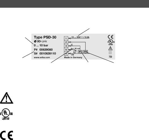
2.4Labelling / safety marks
|
Product label |
|
|
|
EN |
|
Power supply |
||
|
Measuring range |
|
|
|
|
|
|
|
|
|
P# Product No. |
|
|
|
|
S# Serial No. |
Analogue signal |
Switching output 1 Switching output 2 |
|
|
|
|||
If the serial number becomes illegible (e.g.due to mechanical damage or overpainting), traceability will no longer be possible.
Explanation of symbols
General danger symbol
cULus, Underwriters Laboratories Inc.®
The instrument was inspected in accordance with the applicable US standards and certified by UL.
Furthermore, instruments bearing this mark comply with the applicable Canadian standards on safety.
CE, Communauté Européenne
Instruments bearing this mark comply with the relevant European directives.
8 |
WIKA operating instructions pressure switch, model PSD-3x |
11430486.07 04/2015 EN/DE/FR/ES

11430486.07 04/2015 EN/DE/FR/ES
3.Specifications
3.Specifications
3.1Measuring ranges
|
|
|
|
|
|
|
|
|
|
|
|
|
|
|
EN |
|||
Gauge pressure |
|
|
|
|
|
|
|
|
|
|
|
|
|
|
||||
bar |
0 ... |
1 1) |
0 ... |
1.6 1) |
0 ... |
2.5 |
0 ... |
4 |
0 ... |
6 |
0 ... |
10 |
0 ... |
16 |
0 ... |
25 |
|
|
|
0 ... |
40 |
0 ... |
60 |
0 ... |
100 |
0 ... |
160 |
0 ... |
250 |
0 ... |
400 |
0 ... |
600 |
|
|
|
|
psi |
0 ... |
15 1) |
0 ... |
25 1) |
0 ... |
301) |
0 ... |
50 |
0 ... |
100 |
0 ... |
160 |
0 ... |
200 |
0 ... |
300 |
|
|
|
0 ... |
500 |
0 ... |
1,000 |
0 ... |
1,500 |
0 ... |
2,000 |
0 ... |
3,000 |
0 ... |
5,000 |
0 ... |
8,000 |
|
|
|
|
|
|
|
|
|
|
|
|
|
|
|
|
|
|
|
||||
Absolute pressure |
|
|
|
|
|
|
|
|
|
|
|
|
|
|
||||
bar |
0 ... |
1 1) |
0 ... |
1.6 1) |
0 ... |
2.5 |
0 ... |
4 |
0 ... |
6 |
0 ... |
10 |
0 ... |
16 |
0 ... |
25 |
|
|
psi |
0 ... |
15 1) |
0 ... |
25 1) |
0 ... |
30 1) |
0 ... |
50 |
0 ... |
100 |
0 ... |
160 |
0 ... |
200 |
0 ... |
300 |
|
|
|
|
|
|
|
|
|
|
|
|
|
|
|
||||||
Vacuum and +/- measuring range |
|
|
|
|
|
|
|
|
|
|
|
|
||||||
bar |
-1 ... |
0 1) |
-1 ... |
0.6 1) |
-1 ... |
1.5 |
-1 ... |
3 |
-1 ... |
5 |
-1 ... |
9 |
-1 ... |
15 |
-1 ... |
24 |
|
|
psi |
-14.5 ... 0 |
-14.5 ... 15 |
-14.5 ... 30 |
-14.5 ... 50 |
-14.5 ... 100 |
-14.5 ... 160 |
-14.5 ... 200 |
-14.5 ... 300 |
|
|
||||||||
The given measuring ranges are also available in kg/cm2 and MPa.
1) Not available for PSD-31.
Overpressure limit
2 times
1.7 times for the relative pressure measuring ranges 160 psi, 1,000 psi and 1,500 psi
3.2 Display
14-segment LED, red, 4-digit, 9 mm character size
Display can be turned electronically through 180°
Update (adjustable): 100, 200, 500, 1,000 ms
WIKA operating instructions pressure switch, model PSD-3x |
9 |

3.Specifications
3.3Output signals
|
|
Switching output 1 |
Switching output 2 |
Analogue signal |
EN |
|
PNP |
- |
4 ...20 mA (3-wire) |
|
|
PNP |
- |
DC 0 ...10V (3-wire) |
|
|
PNP |
PNP |
- |
|
|
PNP |
PNP |
4 ...20 mA (3-wire) |
|
|
PNP |
PNP |
DC 0 ...10V (3-wire) |
Alternatively also available with an NPN instead of a PNP switching output.
With the IO-Link option, switching output 1 is always PNP.
IO-Link, revision 1.1 (option)
IO-Link is optionally available for all output signals.
With the IO-Link option, switching output SP1 is always PNP.
Zero offset adjustment maximum 3 % of span
Switching thresholds
Switch point 1 and switch point 2 are individually adjustable
Switching functions
Normally open, normally closed, window, hysteresis
Freely adjustable
Switching voltage
Power supply - 1 V
10 |
WIKA operating instructions pressure switch, model PSD-3x |
11430486.07 04/2015 EN/DE/FR/ES
3.Specifications
Switching current
■■ without IO-Link: max. 250 mA
■■ with IO-Link: SP1 max. 100 mA, SP2 max. 250 mA
Settling time
Analogue signal: 3 ms
Switching output: ≤ 10 ms (20 ms with IO-Link)
Load
Analogue signal 4 ... 20 mA: ≤ 0.5 kΩ Analogue signal DC 0 ... 10 V: > 10 kΩ
Service life
100 million switching cycles
|
3.4 Voltage supply |
|
||
|
Power supply |
|
||
|
DC 15 ... 35 V |
|
||
|
Current consumption |
|
||
|
Switching outputs with |
70 mA |
||
EN/DE/FR/ES |
■■ |
Analogue signal 4 ... 20 mA: |
||
■■ |
Analogue signal DC 0 ... 10 V: |
45 mA |
||
IO-Link option causes a deviating current consumption |
||||
|
■■ |
without analogue signal: |
45 mA |
|
04/2015 |
Total current consumption |
|
||
11430486.07 |
■■ |
without IO-Link: max. 600 mA including switching current |
||
■■ |
with IO-Link: max. 450 mA including switching current |
|||
WIKA operating instructions pressure switch, model PSD-3x |
||||
|
||||
EN
11

3.Specifications
3.5Accuracy data
Accuracy, analogue signal
EN ≤ ±1.0 % of span
Including non-linearity, hysteresis, zero offset and end value deviation (corresponds to measured error per IEC 61298-2).Calibrated in vertical mounting position with process connection facing downwards.
Non-linearity: ≤ ±0.5 % of span (BFSL, IEC 61298-2) Long-term drift:≤ ±0.2 % of span (IEC 61298-2)
Accuracy, switching output
Switch point accuracy: ≤ ±1 % of span Adjustment accuracy: ≤ ±0.5 % of span
Display
≤ ±1.0 % of span ± 1 digit
Temperature error in rated temperature range
■■ typical: ≤ ±1.0 % of span ■■ maximum: ≤ ±2.5 % of span
Temperature coefficients in rated temperature range
Mean TC zero point: ≤ ±0.2 % of span/10 K (typical)
Mean TC span: |
≤ ±0.1 % of span/10 K (typical) |
3.6 Reference conditions |
|
Temperature: |
15 ...25 °C (59 ...77 °F) |
Atmospheric pressure: 950 ...1,050 mbar (13.78 ...15.23 psi) |
|
Humidity: |
45 ... 75 % r. h. |
Nominal position: |
Process connection lower mount (LM) |
Power supply: |
DC 24 V |
Load: |
see output signals |
|
|
12 |
WIKA operating instructions pressure switch, model PSD-3x |
11430486.07 04/2015 EN/DE/FR/ES

3.Specifications
11430486.07 04/2015 EN/DE/FR/ES
3.7 Operating conditions |
|
|
|
||
Permissible temperature ranges |
|
|
|||
Medium: |
-20 |
...+85 °C (-4 |
...+185 °F) |
EN |
|
Ambient: |
-20 ... |
+80 °C (-4 |
...+176 °F) |
||
|
|||||
Storage: |
-20 ... |
+80 °C (-4 |
...+176 °F) |
|
|
Nominal temperature: |
0 ... |
80 °C (32 ... |
176 °F) |
|
|
Humidity
45 ... 75 % r. h.
Vibration resistance
10 g (IEC 60068-2-6, under resonance)
Shock resistance
50 g (IEC 60068-2-27, mechanical)
Service life, mechanics
100 million load cycles (10 million load cycles for measuring ranges > 600 bar/7,500 psi)
Ingress protection
IP 65 and IP 67
The stated ingress protection (per IEC 60529) only applies when plugged in using mating connectors that have the appropriate ingress protection.
Mounting position as required
WIKA operating instructions pressure switch, model PSD-3x |
13 |

3.Specifications
3.8Materials
|
Wetted parts |
|
EN |
Process connection: |
Stainless steel 316L |
|
Pressure sensor: |
< 9.8 bar:Stainless steel 316L |
|
|
≥ 9.8 bar:Stainless steel 13-8 PH |
Non-wetted parts
Case: |
Stainless steel 304 |
Keyboard: |
TPE-E |
Display window: PC |
|
Display head: |
PC+ABS-Blend |
Options for specific media
Medium |
Option |
|
|
Oil and grease free |
Residual hydrocarbon: < 1,000 mg/m2 |
||
Oxygen, oil and grease free |
■■ Residual hydrocarbon: < 200 mg/m2 |
||
|
■■ Packaging: Protection cap on the process connection |
||
|
■■ Maximum permissible temperature -20 ...+60 °C (-4 ...+140 °F) |
||
|
■■ Only available for PSD-30 |
||
|
■■ Available measuring ranges: |
||
|
- 0 ... |
10 to 0 ... |
400 bar gauge |
|
- -1 ... |
9 to -1 ... |
24 bar |
■■ Factory supplied without sealing
14 |
WIKA operating instructions pressure switch, model PSD-3x |
11430486.07 04/2015 EN/DE/FR/ES

3.Specifications
3.9Process connections
Available connections, model PSD-30
Standard |
Thread |
EN |
|
||
DIN 3852-E |
G ¼ A |
|
|
G ½ A |
|
EN 837 |
G ¼ B |
|
|
G ¼ female |
|
|
G ½ B |
|
ANSI / ASME B1.20.1 |
¼ NPT |
|
|
½ NPT |
|
ISO 7 |
R ¼ |
|
KS |
PT ¼ |
|
-G ¼ female (Ermeto compatible)
Other connections on request.
Available connections, model PSD-31
Standard Thread
-G ½ B with flush diaphragm
11430486.07 04/2015 EN/DE/FR/ES
WIKA operating instructions pressure switch, model PSD-3x
15

3.Specifications
Sealings
Process connection per DIN 3852-E
EN |
|
Standard |
NBR |
|
|
Option 1 |
without |
|
|
Option 2 |
FPM/FKM |
Process connection per EN 837 1)
Standard |
without |
Option 1 |
Copper |
Option 2 |
Stainless steel |
1) Process connections per EN 837 with female threads do not include any seal.
Process connection G ½ B flush
Standard |
NBR |
Option |
FPM/FKM |
3.10 Electrical connections
Connections
Circular connector M12 x 1 (4-pin)
Circular connector M12 x 1 (5-pin) 1)
1) Only for version with two switching outputs and additional analogue signal
Electrical safety |
S+ / SP1 / SP2 vs. U- |
|
Short-circuit resistance: |
||
Reverse polarity protection: |
U+ vs. U- |
|
Insulation voltage: |
DC 500 V |
|
Overvoltage protection: |
DC 40 V |
|
|
|
|
16 |
WIKA operating instructions pressure switch, model PSD-3x |
|
11430486.07 04/2015 EN/DE/FR/ES

3.Specifications
11430486.07 04/2015 EN/DE/FR/ES
3.11 CE conformity |
|
|
Pressure equipment directive |
|
|
97/23/EC |
EN |
|
EMC directive |
|
|
2004/108/EC, EN 61326 emission (group 1, class B) and interference immunity (industrial application) |
|
|
3.12 Manufacturer's declaration |
|
|
RoHS conformity |
|
|
2011/65/EU |
|
|
3.13 Approvals |
|
|
■■ |
cULus, safety (e.g.electr.safety, overpressure, ...), USA, Canada |
|
■■ |
EAC, import certificate, customs union Russia/Belarus/Kazakhstan |
|
■■ |
CRN, safety (e.g.electr.safety, overpressure, ...), Canada |
|
Approvals and certificates, see website
For special model numbers, e.g.PSD-30000, please note the specifications stated on the delivery note.
For further specifications seeWIKA data sheet PE 81.67 and the order documentation.
WIKA operating instructions pressure switch, model PSD-3x |
17 |

4. Design and function / 5. Transport, packaging and storage
4. Design and function
4.1 Description
EN By means of a sensor element and by supplying power, the prevailing pressure is converted into a switching signal or an amplified standardised electrical signal via the deformation of a diaphragm.This electrical signal varies in proportion to the pressure and can be evaluated accordingly.
PSD-30:Process connection with internal diaphragm (standard version).
PSD-31:Process connection with flush diaphragm for highly viscous or crystallising media that may clog the bore of the process connection.
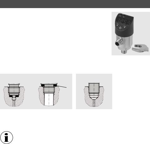
4.2 Scope of delivery
Cross-check the scope of delivery with the delivery note.
For flush design (model PSD-31) with pre-mounted sealings and protection cap.
5. Transport, packaging and storage
For the protection of the diaphragm, the flush design (model PSD-31) is delivered with a special protection cap.
■■ In order to avoid damage at the diaphragm and/or the process connection thread, remove the protection cap by hand only just before installation.
■■ Keep the protection cap for subsequent storage or transport.
■■ Fit the protection cap before dismounting and transporting the instrument.
5.1 Transport
Check the instrument for any damage that may have been caused by transport.With flush design (model PSD-31), additionally check the diaphragm for any optical damage.
Obvious damage must be reported immediately.
18 |
WIKA operating instructions pressure switch, model PSD-3x |
11430486.07 04/2015 EN/DE/FR/ES

5.Transport, packaging and storage / 6. Commissioning, ...
5.2Packaging
Do not remove packaging until just before mounting. |
|
|
Keep the packaging as it will provide optimum protection during transport (e.g. change in installation |
|
|
site, sending for repair). |
EN |
|
5.3 Storage |
|
|
Permissible conditions at the place of storage: |
|
|
■■ |
Storage temperature: -20 ... +80 °C |
|
■■ |
Humidity:45 ...75 % relative humidity (no condensation) |
|
In order to protect the diaphragm, mount the protection cap before storing the instrument.
WARNING!
Before storing the instrument (following operation), remove any residual media.This is of particular importance if the medium is hazardous to health, e.g. caustic, toxic, carcinogenic, radioactive, etc..
11430486.07 04/2015 EN/DE/FR/ES
6. Commissioning, operation
CAUTION!
Only use the pressure switch if it is in perfect condition with respect to safety.
Check the following points before commissioning:
■■ Check the diaphragm for any visible damage, since this is a safety-relevant component.
■■ Leaking fluid is indicative of damage.
Required tool: SW 27 open-ended spanner, screwdriver
WIKA operating instructions pressure switch, model PSD-3x |
19 |
6.Commissioning, operation
6.1Making the mechanical connection
|
■■ |
With flush process connections (model PSD-31), remove the protection |
|||
|
|
cap not until shortly before mounting. During installation, ensure that the |
|||
EN |
|
diaphragm is not damaged. |
|
||
■■ |
The sealing faces at the instrument always have to be clean. |
||||
|
|||||
|
■■ |
Only ever screw in, or unscrew, the instrument via the spanner flats. |
|||
|
|
Never use the case as a working surface. |
|
||
|
■■ |
The correct torque depends on the dimensions of the pressure connec- |
|||
|
|
tion and the gasket used (form/material). |
|
||
|
■■ |
When screwing in, do not cross the threads. |
|
||
|
■■ |
For information on tapped holes and welding sockets, see Technical |
|||
|
|
Information IN 00.14 at www.wika.de. |
|
||
|
Seal |
|
|
||
|
Parallel threads |
per DIN 3852-E |
Tapered threads |
||
|
|
per EN 837 |
NPT, R and PT |
||

Correct sealing of the process connections with parallel threads at the sealing face must be made using suitable flat gaskets, sealing rings orWIKA profile sealings.
The sealing of tapered threads (e.g.NPT threads) is made by providing the thread with additional sealing material such as, for example, PTFE tape (EN 837-2).
For further information on seals seeWIKA data sheet AC 09.08 or under www.wika.com.
20 |
WIKA operating instructions pressure switch, model PSD-3x |
11430486.07 04/2015 EN/DE/FR/ES
6.Commissioning, operation
6.2Making the electrical connection
■■ |
The instrument must be earthed via the process connection! |
|
|
■■ |
The power supply for the pressure switch must be made via an energy-limited electrical circuit in |
|
|
|
accordance with section 9.3 of UL/EN/IEC 61010-1 or an LPS to UL/EN/IEC 60950-1 or class 2 in |
EN |
|
|
accordance with UL1310/UL1585 (NEC or CEC).The power supply must be suitable for operation |
||
|
|
||
|
above 2,000 m should the pressure switch be used at this altitude. |
|
|
■■ |
For cable outlets, make sure that no moisture enters at the cable end. |
|
|
Connection diagrams |
|
|
|
Circular connector M12 x 1; 4-pin |
Circular connector M12 x 1; 5-pin |
|
|
Assignment |
|
|
|
|
|
|
|
Assignment |
|
|
|
|
|
|
||||
U+ |
|
U- |
|
S+ |
|
SP1 / C |
|
SP2 |
|
U+ |
|
U- |
|
S+ |
|
SP1 / C |
|
SP2 |
|
|
|
|
|
|
|
|
|||||||||||
1 |
|
3 |
|
2 |
|
4 |
|
2 |
|
1 |
|
3 |
|
5 |
|
4 |
|
2 |
11430486.07 04/2015 EN/DE/FR/ES
Zero point adjustment
Check the indicated zero point on the display during commissioning.
Should an offset be displayed as a result of installation, this can be reset in programming mode with the
0SET parameter
■■ Carry out zero point adjustment for relative and vacuum pressure measuring ranges in a depressurised state.
■■ Carry out zero point adjustment of absolute pressure ranges from 0 bar absolute
(vacuum).Since appropriate references are required for this, we recommend that this is only carried out by the manufacturer.
WIKA operating instructions pressure switch, model PSD-3x |
21 |

|
|
6. Commissioning, operation |
|
|
6.3 Operating modes |
||
|
System start |
||
EN |
■■ Display is fully activated for 2 sec. |
||
■■ When the pressure switch is powered up within the range of the hysteresis, the output switch is set to |
|||
|
|||
|
|
"not active" by default. |
|
|
Display mode |
||
|
Normal operation, display pressure value |
||
|
Programming mode |
||
|
Setting the parameters |
||
|
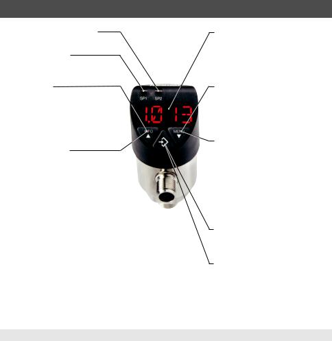
6.4 Keys and functions |
||
|
The pressure switch has two operating modes, the display mode and the programming mode. The |
||
|
selected operating mode determines the respective function of the key. |
||
|
|
|
|
|
|
Jumping into the programming mode |
|
|
|
Keep the "MENU" key pressed for approx.5 seconds.If the password is set to ≠ |
|
|
|
0000, a password will be requested. If authentication is successful, then it enters |
|
|
|
the programming mode, otherwise it reverts to display mode. |
|
|
|
|
|
|
|
Returning to the display mode |
|
|
|
Simultaneous pressing of both keys. |
|
|
|
|
|
22 |
WIKA operating instructions pressure switch, model PSD-3x |
11430486.07 04/2015 EN/DE/FR/ES
6. Commissioning, operation
Status switching output 2 (optional)
Status switching output 1
Display mode
Short press Display of the unit
Long press
Display of the set parameters see chapter 6.4 "Parameters"
Programming mode
Short press Menu up
Parameter value up (step-wise)
Long press Menu up
Parameter value up (fast)
EN/DE/FR/ES04/2015
11430486.07 WIKA operating instructions pressure switch, model PSD-3x
4-digit LED display |
|
|
■■ Display pressure value |
|
|
■■ |
Display menu item |
|
■■ |
Display parameter |
EN |
|
|
|
|
|
|
Display mode
Short press Display of the unit
Long press
Jumping into the programming mode
Programming mode
Short press Menu down
Parameter value down (step-wise)
Long press Menu down
Parameter value down (fast)
Display mode
Short press Display of the unit
Programming mode
Short press Select menu item
Confirmation of the input
23

6.Commissioning, operation
6.5Parameters
Parameter
EN SP1/SP2 FH1/FH2 RP1/RP2 FL1/FL2 EF
RES DS1/DS2 DR1/DR2 OU1 OU2
UNIT 0SET DISM
DISU
DISR
RHL
PAS
TAG
24
Description
Hysteresis function:Switch point switching output (1 or 2) Window function:Window high switching output (1 or 2) Hysteresis function:Reset point switching output (1 or 2) Window function:Window low switch output (1 or 2)
Extended programming functions
Return the set parameter to the factory settings
Switch delay time, which must occur without interruption before any electrical signal change occurs (SP1 or SP2) Switch delay time, which must occur without interruption before any electrical signal change occurs (RP1 or RP2) Switching function switching output (1 or 2)
HNO = hysteresis function, normally open HNC = hysteresis function, normally closed FNO = window function, normally open FNC = window function, normally closed
Unit switching
Offset adjustment (3 % of span)
Display value in display mode
ACT = actual pressure value;LOW, HIGH = minimum, maximum pressure value OFF = display off;
SP1/FH1 = function switch point 1, RP1/FL1 = function reset point 1, SP2/FH2 = function switch point 2, RP2/FL2 = function reset point 2
Display update 1, 2, 5, 10 updates/second Rotate display indicator by 180°
Clear the Minand Max-value memories
Password input, 0000 = no password Password input digit by digit
Input of a 16-figure alphanumeric measuring point number
WIKA operating instructions pressure switch, model PSD-3x
11430486.07 04/2015 EN/DE/FR/ES

6. Commissioning, operation
11430486.07 04/2015 EN/DE/FR/ES
Menu (programming and factory setting)
|
|
|
Display mode |
|
|
|
|
|
|
|
|
|||||
|
|
|
|
Long press on menu key |
|
|
Factory setting: |
|
|
|||||||
|
Programming mode |
|
|
|
|
|
EN |
|||||||||
SP1 / FH1 |
|
|
|
|
|
Value |
(Min: MBA +0.5 % |
Max:MBE) |
Instrument nominal pressure |
|
||||||
|
|
|
|
|
|
|
||||||||||
RP1 / FL1 |
|
|
|
|
|
Value |
(Min: MBA |
|
Max:SP1 -0.5 %) |
Instrument nominal pressure -10 % |
|
|
||||
|
|
|
|
|
|
|||||||||||
SP2 / FH2 |
|
|
|
|
Value |
(Min: MBA +0.5 % |
Max:MBE) |
Instrument nominal pressure |
|
|
||||||
|
|
|
|
|||||||||||||
RP2 / FL2 |
|
|
|
|
Value |
(Min: MBA |
|
Max:SP2 -0.5 %) |
Instrument nominal pressure -10 % |
|
|
|||||
|
|
|
|
|
||||||||||||
|
EF |
|
|
|
|
RES |
|
Yes / No |
Reset to factory setting |
|
|
|
||||
|
|
|
|
|
||||||||||||
|
|
|
|
|
|
|
|
|
||||||||
|
|
|
|
|
|
|
|
|||||||||
|
|
|
|
|
|
|
|
|
DS1 |
|
Value |
0 ... 50 s |
|
0 s |
|
|
|
|
|
|
|
|
|
|
|
|
|
|
|
||||
|
|
|
|
|
|
|
|
|
|
|
|
|
||||
|
|
|
|
|
|
|
|
|
DR1 |
|
Value |
0 ... 50 s |
|
0 s |
|
|
|
|
|
|
|
|
|
|
|
|
|
|
|
||||
|
|
|
|
|
|
|
|
|
DS2 |
|
Value |
0 ... 50 s |
|
0 s |
|
|
|
|
|
|
|
|
|
|
|
|
|
|
|
||||
|
|
|
|
|
|
|
|
|
DR2 |
|
Value |
0 ... 50 s |
|
0 s |
|
|
|
|
|
|
|
|
|
|
|
|
|
|
|
||||
|
|
|
|
|
|
|
|
|
OU1 |
|
PARA |
HNO, HNC, FNO, FNC |
HNO |
|
|
|
|
|
|
|
|
|
|
|
|
|
|
|
|||||
|
|
|
|
|
|
|
|
|
OU2 |
|
PARA |
HNO, HNC, FNO, FNC |
HNO |
|
|
|
|
|
|
|
|
|
|
|
|
|
|
|
|||||
|
|
|
|
|
|
|
|
|
UNIT |
|
Unit |
BAR, MPA, KPA, PSI, KG/cm2 |
Order-related |
|
|
|
|
|
|
|
|
|
|
|
|
|
|
|
|||||
|
|
|
|
|
|
|
|
|
0SET |
|
Yes / No |
Zero point adjustment 3% of span |
|
|
|
|
|
|
|
|
|
|
|
|
|
|
|
|
|
||||
|
|
|
|
|
|
|
|
|
DISM |
|
PARA |
ACT, HIGH, LOW, OFF, SP1/FH1, RP1/ |
ACT |
|
|
|
|
|
|
|
|
|
|
|
|
|
|
|
|||||
|
|
|
|
|
|
|
|
|
|
|
|
FL1, SP2/FH2, RP2/FL2 |
|
|
|
|
|
|
|
|
|
|
|
|
|
DISU |
|
Value |
1/2/5/10 update/second |
5 |
|
|
|
|
|
|
|
|
|
|
|
|
|
|
|
|||||
|
|
|
|
|
|
|
|
|
DISR |
|
Yes / No |
Rotate display by 180° |
|
|
|
|
|
|
|
|
|
|
|
|
|
|
|
|
|
||||
|
|
|
|
|
|
|
|
|
RHL |
|
Yes / No |
Reset HIGH, LOW |
|
|
|
|
|
|
|
|
|
|
|
|
|
|
|
|
|
||||
|
|
|
|
|
|
|
|
|
PAS |
|
Value |
Password |
without |
|
|
|
|
|
|
|
|
|
|
|
|
|
|
|
|||||
|
|
|
|
|
|
|
|
|
TAG |
|
Value |
Measuring point number |
without |
|
|
|
END |
|
|
END |
|
Legend: |
|
|
|
|
|
||||||
|
|
|
|
|
|
|
||||||||||
|
|
|
Display mode |
|
|
MBA = Start of measuring range |
|
|
|
|||||||
|
|
|
|
|
MBE = End of measuring range |
|
|
|
||||||||
|
|
|
|
|
|
|
|
|
|
|
|
|
||||
WIKA operating instructions pressure switch, model PSD-3x |
25 |
|
|
|||||||||||||
6.Commissioning, operation
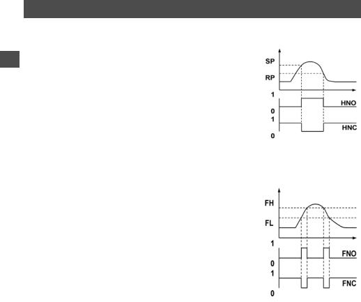
6.6Switching functions
Hysteresis function
EN If the system pressure fluctuates around the set point, the hysteresis keeps the switching status of the outputs stable. With increasing system pressure, the output switches when reaching the switch point (SP).
■■ Contact normally open (HNO):active ■■ Contact normally closed (HNC):inactive
With system pressure falling again, the output will not switch back before the reset point (RP) is reached.
■■ Contact normally open (HNO):inactive ■■ Contact normally closed (HNC):active
Window function
The window function allows for the control of a defined range.
When the system pressure is between window High (FH) and window Low (FL), the output switches on.
■■ Contact normally open (FNO):active ■■ Contact normally closed (FNC):inactive
When the system pressure is outside window High (FH) and window Low (FL), the output does not switch on.
■■ Contact normally open (FNO):inactive ■■ Contact normally closed (FNC):active
Fig.: Hysteresis function
Fig.: Window function
26 |
WIKA operating instructions pressure switch, model PSD-3x |
11430486.07 04/2015 EN/DE/FR/ES
6. Commissioning, operation
11430486.07 04/2015 EN/DE/FR/ES
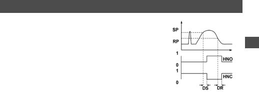
Delay times (0 ... 50 s)
This makes it possible to filter out unwanted pressure peaks of a short duration or a high frequency (damping).
The pressure must be present for at least a certain pre-set time for the EN output to switch on. The output does not immediately change its status
when it reaches the switching event (SP), but rather only after the pre-set delay time (DS).
If the switching event is no longer present after the delay time, the switch output does not change.
The output only switches back when the system pressure has fallen
down to the reset point (PR) and stays at or below the reset point (RP) Fig.: Delay times for at least the pre-set delay time (DR).
If the switching event is no longer present after the delay time, the switch output does not change.
6.7 Description of the IO-Link functionality (optional)
IO-Link is a point-to-point connection for the communication of the PSD-3x with an IO-Link master.
IO-Link specification:Version 1.1
A detailed description of the IO-Link functionality and the device description file (IODD) can be found online on the product details page of the pressure switch at www.wika.com.
WIKA operating instructions pressure switch, model PSD-3x |
27 |
7. Maintenance and cleaning
7. Maintenance and cleaning
7.1 Maintenance
EN This instrument is maitenance-free.
Repairs must only be carried out by the manufacturer.
7.2 Cleaning
CAUTION!
■■ Before cleaning, correctly disconnect the instrument from the pressure supply, switch it off and disconnect it from the mains.
■■ Clean the instrument with a moist cloth.
■■ Electrical connections must not come into contact with moisture.
■■ Wash or clean the dismounted instrument before returning it in order to protect personnel and the environment from exposure to residual media.
■■ Residual media in dismounted instruments can result in a risk to persons, the environment and equipment.
■■ Take sufficient precautionary measures.
■■ Do not use any pointed or hard objects for cleaning, as they may damage the diaphragm of the process connection.
For information on returning the instrument see chapter 9.2 "Return".
28
WIKA operating instructions pressure switch, model PSD-3x
11430486.07 04/2015 EN/DE/FR/ES

8. Faults
8. Faults
In the event of any faults, first check whether the pressure switch is mounted correctly, |
EN |
mechanically and electrically. |
|
Error display
Via the instrument's display internal errors of the instrument are output.
The following table shows the error codes and their meaning.
11430486.07 04/2015 EN/DE/FR/ES
Error |
Description |
ATT1 |
On changing the switch point, the system automatically reduces the reset point. |
ATT2 |
Zero-point adjustment error, current pressure is outside the limits |
ATT3 |
Password entered for menu access is incorrect |
ATT4 |
TAG cannot be shown in the display (e.g.special characters) |
ERR |
Internal error |
OL |
Overpressure, measuring range exceeded > approx.5% (display blinks) |
UL |
Underpressure, below measuring range < approx.5 % (display blinks) |
Acknowledgement of an error display by pressing the „Enter“ key.
WIKA operating instructions pressure switch, model PSD-3x
29

8. Faults
|
|
Problem |
Possible cause |
Measure |
|
|
|
No output signal |
Cable break |
Check the continuity |
|
|
|
No output signal |
No/wrong power supply |
Rectify the power supply |
|
EN |
|||||
|
No/wrong output signal |
Wiring error |
Observe the pin assignment |
||
|
|
Constant output signal upon change |
Mechanical overload caused by over- |
Replace instrument; if it fails repeatedly, |
|
|
|
in pressure |
pressure |
contact the manufacturer |
|
|
|
Deviating zero point signal |
Overpressure limit exceeded |
Observe the permissible overpressure limit |
|
|
|
Signal span too small |
Mechanical overload caused by over- |
Replace instrument; if it fails repeatedly, |
|
|
|
|
pressure |
contact the manufacturer |
|
|
|
Signal span too small |
Power supply too high/low |
Rectify the power supply |
|
|
|
Signal span drops |
Humidity has entered |
Assemble the cable correctly |
|
|
|
Signal span drops/too small |
Diaphragm damaged, e.g. due to |
Contact manufacturer and replace |
|
|
|
|
impacts, abrasive/aggressive medium; |
instrument |
|
|
|
|
corrosion at diaphragm/process |
|
|
|
|
|
connection |
|
If complaint is unjustified, we will charge you the complaint processing fees.
CAUTION!
If deficiencies cannot be eliminated by means of the measures listed above, shut down the instrument immediately, and ensure that pressure and/or signal are no longer present, and secure the instrument from being put back into operation inadvertently. In this case, contact the manufacturer.If a return is needed, follow the instructions given in chapter 9.2 "Return".
30
WIKA operating instructions pressure switch, model PSD-3x
11430486.07 04/2015 EN/DE/FR/ES
 Loading...