


|
Operating instructions |
|
|
Betriebsanleitung |
|
|
Mode d'emploi |
|
|
Manual de instrucciones |
|
|
|
|
Thermowells |
|
GB |
|
|
|
Schutzrohre |
|
D |
|
|
|
Doigts de gant |
|
F |
|
|
|
Vainas |
|
E |
Examples/Beispiele/Exemples/Ejemplos
|
|
|
|
|
GB |
Operating instructions thermowells |
Page |
3 |
- 12 |
|
|
|
|
|
D |
Betriebsanleitung Schutzrohre |
Seite |
13 |
- 22 |
|
|
|
|
|
F |
Mode d'emploi doigts de gant |
Page |
23 |
- 32 |
|
|
|
|
|
E |
Manual de instrucciones vainas |
Página |
33 |
- 41 |
©WIKA AlexanderWiegand SE & Co.KG 2010
Prior to starting any work, read the operating instructions! Keep for later use!
Vor Beginn aller Arbeiten Betriebsanleitung lesen!
Zum späteren Gebrauch aufbewahren!
Lire le mode d'emploi avant de commencer toute opération ! A conserver pour une utilisation ultérieure !
¡Leer el manual de instrucciones antes de comenzar cualquier trabajo! ¡Guardar el manual para una eventual consulta posterior!
11405821.06 09/2010 GB/D/F/E
2 |
WIKA operating instructions thermowells |

Contents
Contents
GB
1. |
General information |
4 |
2. |
Safety |
5 |
3. |
Specifications |
6 |
4. |
Design and function |
6 |
5. |
Transport, packaging and storage |
6 |
6. |
Commissioning, operation |
7 |
7. |
Maintenance and cleaning |
9 |
8. |
Faults |
10 |
9. |
Dismounting, return and disposal |
10 |
11405821.06 09/2010 GB/D/F/E
WIKA operating instructions thermowells |
3 |

1.General Information
1.General Information
■■The thermowell described in the operating instructions has been manufactured using state-of-
|
the-art technology.All components are subject to stringent quality and environmental criteria |
GB |
|
|
during production.Our management systems are certified to ISO 9001 and ISO 14001. |
|
■■These operating instructions contain important information on handling the thermowell.Working safely requires that all safety instructions and work instructions are observed.
■■Observe the relevant local accident prevention regulations and general safety regulations for the thermowell's range of use.
■■The operating instructions are part of the instrument and must be kept in the immediate vicinity of the thermowell and readily accessible to skilled personnel at any time.
■■Skilled personnel must have carefully read and understood the operating instructions, prior to beginning any work.
■■The manufacturer‘s liability is void in the case of any damage caused by using the product contrary to its intended use, non-compliance with these operating instructions, assignment of insufficiently qualified skilled personnel or unauthorised modifications to the thermowell.
■■The general terms and conditions, contained in the sales documentation, shall apply.
■■Subject to technical modifications.
■■Further information:
- Internet address: |
www.wika.de / www.wika.com |
||
- Application consultant: |
Tel.: |
(+49) |
9372/132-0 |
|
Fax: |
(+49) |
9372/132-406 |
|
E-Mail: |
info@wika.de |
|
Explanation of symbols
WARNING!
...indicates a potentially dangerous situation, which can result in serious injury or death, if not avoided.
CAUTION!
...indicates a potentially dangerous situation, which can result in light injuries or damage to equipment or the environment, if not avoided.
Information
...points out useful tips, recommendations and information for efficient and troublefree operation.
WARNING!
...indicates a potentially dangerous situation that can result in burns, caused by hot surfaces or liquids, if not avoided.
11405821.06 09/2010 GB/D/F/E
4 |
WIKA operating instructions thermowells |

2.Safety
2.Safety
WARNING!
Before installation, commissioning and operation, ensure that the appropriate thermo- GB well has been selected in terms of measuring range, design and specific measuring conditions.
Before installation, commissioning and operation, ensure that the thermowell material used is chemically resistant/neutral to the medium being measured and that it withstands the mechanical stresses from the process.
Non-observance can result in serious injury and/or damage to equipment.
Further important safety instructions can be found in the individual chapters of these operating instructions.
2.1 Intended use
Thermowells are used to protect temperature sensors from the process conditions.Furthermore, thermowells enable the removal of the temperature sensor without having to shut down the process;and they guard against damage to either the environment or to personnel, which might be caused by escaping process media.
The thermowell has been designed and built solely for the intended use described here, and may only be used accordingly.
The technical specifications contained in these operating instructions must be observed.Should the thermowell be improperly handled or operated outside of its technical specifications, it has to be inspected immediately.
The manufacturer shall not be liable for claims of any type based on operation contrary to the intended use.
11405821.06 09/2010 GB/D/F/E
2.2 Personnel qualification
WARNING!
Risk of injury should qualification be insufficient!
Improper handling can result in considerable injury and damage to equipment. The activities described in these operating instructions may only be carried out by skilled personnel who have the qualifications described below.
Skilled personnel
Skilled personnel are understood to be personnel who, based on their technical training, knowledge of measurement and control technology and on their experience and knowledge of country-specific regulations, current standards and directives, are capable of carrying out the work described and independently recognising potential hazards.
Special operating conditions require further appropriate knowledge, e.g.of aggressive or toxic media.
WIKA operating instructions thermowells |
5 |

2.Safety / 3.Specifications / 4.Design, function / 5.Transport, packaging ...
2.3 Special hazards
WARNING!
GB For hazardous media such as oxygen, acetylene, flammable or toxic gases or liquids, and refrigeration plants, compressors, etc., in addition to all standard regulations, the appropriate existing codes or regulations must also be followed.
Make sure that the thermowell is sufficiently earthed.
WARNING!
Residual media on dismounted thermowells can result in a risk to persons, the environment and the equipment.Take sufficient precautionary measures.
3.Specifications
For specifications see the appropriateWIKA data sheets for current thermowell versions and the order documentation.
4.Design and function
4.1 Description
Metal thermowells can be manufactured as solid-machined or fabricated versions.Thermowells can be connected to the process by screw-, weldor flange-fitting.The temperature sensor is directly fastened to the thermowell using a female or male thread or by means of an neck tube.
If thermowells made of metallic materials do not show a sufficient temperature or corrosion resistance during continuous operation at temperatures above 1200 °C, ceramic thermowells should be used.
4.2 Scope of delivery
Cross-check scope of delivery with delivery note.
5.Transport, packaging and storage
5.1 Transport
Check thermowell for any damage that may have been caused by transport.Obvious damage must be reported immediately.
5.2 Packaging
Do not remove packaging until just before mounting.
Keep the packaging as it will provide optimum protection during transport (e.g.change in installation site, sending for repair).
11405821.06 09/2010 GB/D/F/E
6 |
WIKA operating instructions thermowells |

5.Transport, packaging and storage / 6.Commissioning, operation
5.3 Storage |
|
Avoid exposure to the following factors: |
|
■■ Direct sunlight or proximity to hot objects (for thermowells with plastic coating) |
GB |
■■ Mechanical vibration, mechanical shock (putting it down hard) |
WARNING!
Before storing the thermowell (following operation), remove any residual media.This is of particular importance if the medium is hazardous to health, e.g.caustic, toxic, carcinogenic, radioactive, etc.
6.Commissioning, operation
6.1 Mounting
During mounting (especially with ceramic thermowells) the thermowells should not be subjected to thermal shocks or mechanical impacts.
Insert the thermowell into the process adapter without forcing or damaging it.The thermowell must not be bent or altered in order to mount it.
The exception is the retrospective machining of the support ring in order that the thermowell is supported free of play within the nozzle ("interference fit").The retrospective adjustment of a support ring with a loose fit is not permissible.In general, thermowells with a support ring are not recommended within ASME PTC 19.3TW 2010 and are outside of the scope of the standard.
It is recommended to mount the temperature measuring instrument into the thermowell using a suitable sealing material to avoid, for example, humidity ingress.
In general, the tip of the thermowell should be placed in the middle third of the pipe, though the position may differ in special cases.It must be ensured that the measuring element (Pt100, thermocouple, bimetal, etc.) is completely exposed to the medium and is not shielded by the
flange stubs.If, as a result of a small pipe diameter, this cannot be ensured, a pipe expansion can be inserted around the measuring point.
Expansion of the pipe diameter from DN 40 to DN 80
11405821.06 09/2010 GB/D/F/E
WIKA operating instructions thermowells |
7 |
6.Commissioning, operation
Screw-fitting thermowells
When using parallel threads, a suitable seal should be used when mounting.Tapered threads can be sealed by suitable seals or an additional welded seam.The correct tightening torques and
GB suitable tools (e.g.spanner) should be used.
Weld-fitting thermowells
Weld-in thermowells can be mounted into the process directly (pipe or vessel wall) or by using a welding socket.Make sure that the weld seam is clean and that suitable equipment is used.If necessary, heat-treat the weld seams.
Thermowells with flange connection
The flange dimensions of the thermowell must match those of the mating flange on the process side.The seals used must be suitable for the process and the flange geometries (consult the delivery note).The correct tightening torques and suitable tools (e.g.spanner) should be used for installation.For thermowells with a collar, make sure that it matches the inner diameter of the coupling and is supported by it.In the case of an interference collar, they should be adapted to the inner diameter of the coupling.
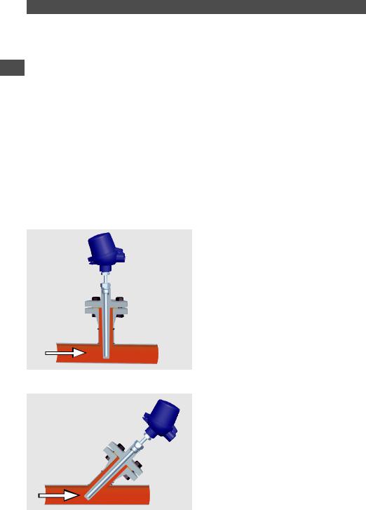
Irrespective of the process connection, 3 mounting positions of thermowells in pipes are possible: ■■ Right-angled position with respect to the flow (most unfavourable position)
■■ Tilted position with respect to the flow (tip inclined towards the flow direction is preferred)
11405821.06 09/2010 GB/D/F/E
8 |
WIKA operating instructions thermowells |
6.Commissioning, operation / 7.Maintenance and cleaning
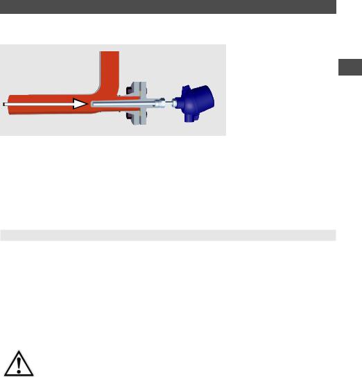
■■Flow towards the tip in an elbow (most favourable position)
GB
The insertion length and the diameter of the thermowell are dependent on the process conditions, especially on the flow rate of the measured medium.
The regulations in accordance withVDI/VDE 3511-5, DIN 43772 Appendix 1/2 and the AD Codes must be observed.
7.Maintenance and cleaning
7.1 Maintenance
In general, thermowells are maintenance-free.
We recommend a visual check of the thermowell for leaks and damages at regular intervals. Make sure that the seal is in perfect condition!
Repairs should only be carried out by the manufacturer or, following prior consultation, by correspondingly qualified skilled personnel.
7.2 Cleaning
CAUTION!
Wash or clean the dismounted instrument before returning it, in order to protect staff and the environment from exposure to residual media.
 For information on returning the thermowell see chapter "9.2 Return".
11405821.06 09/2010 GB/D/F/E
WIKA operating instructions thermowells |
9 |

8.Faults / 9.Dismounting, return and disposal
8.Faults
|
|
Faults |
|
Causes |
|
Measures |
|
GB |
|||||||
|
Not possible to insert the |
|
Foreign bodies in the thermowell |
|
Remove foreign bodies |
||
|
|
|
|||||
|
|
temperature sensor into the |
|
|
|
|
|
|
|
|
Damaged or contaminated |
|
Clean or recut the thread |
||
|
|
thermowell |
|
thermowell or temperature sensor |
|
|
|
|
|
|
|
fastening thread |
|
|
|
|
|
|
|
Sensor dimension and those of the |
|
Check order documentation |
|
|
|
|
|
inner diameter of the thermowell do |
|
|
|
|
|
|
|
not match |
|
|
|
|
|
|
|
Thermowell or sensor has been |
|
Return for repair |
|
|
|
|
|
bent or damaged during installation |
|
|
|
|
|
Leakage of process media |
|
Error during installation or defective |
|
Check the seal, check the |
|
|
|
■■ at the connection between |
|
seals |
|
tightening torques |
|
|
|
the process and the |
|
|
|
|
|
|
|
thermowell |
|
|
|
|
|
|
|
■■ from the interface between |
|
Damage, e.g.caused by operating |
|
Safe operation of the plant can no |
|
|
|
the thermowell and the |
|
the thermowell under a resonant |
|
longer be guaranteed |
|
|
|
sensor |
|
vibration load |
|
(in the worst case, this might |
|
|
|
|
|
|
|
||
|
|
|
|
|
|
result in a complete rupture of the |
|
|
|
|
|
|
|
thermowell) |
In the case of critical installations, we recommend calculating the harmonic frequency of the thermowell according to ASME PTC 19.3 or Dittrich/Klotter.This engineering service is offered by WIKA.
9.Dismounting, return and disposal
WARNING!
Residual media on dismounted thermowells can result in a risk to persons, the environment and equipment.Take sufficient precautionary measures.
9.1 Dismounting
WARNING!
Risk of burns!
Let the instrument cool down sufficiently before dismounting it!
When dismounting it, there is a risk that dangerously hot pressure media may escape.
Only disconnect thermowells once the system has been depressurised!
11405821.06 09/2010 GB/D/F/E
10 |
WIKA operating instructions thermowells |
9.Dismounting, return and disposal
9.2 Return
WARNING!
Strictly observe when shipping the instrument: GB
All instruments delivered toWIKA must be free from any kind of hazardous substances (acids, bases, solutions, etc.).
When returning the instrument, use the original packaging or a suitable transport package.
To avoid damage:
1.Wrap the instrument in an antistatic plastic film.
2.Place the instrument, along with the shock-absorbent material, in the packaging. Place shock-absorbent material evenly on all sides of the transport packaging.
3.If possible, place a bag, containing a desiccant, inside the packaging.
4.Label the shipment as transport of a highly sensitive measuring instrument.
Enclose the completed return form with the instrument.
The return form is available on the internet:
www.wika.de / Service / Return
9.3 Disposal
Incorrect disposal can put the environment at risk.
Dispose of instrument components and packaging materials in an environmentally compatible way and in accordance with the country-specific waste disposal regulations.
11405821.06 09/2010 GB/D/F/E
WIKA operating instructions thermowells |
11 |

GB
11405821.06 09/2010 GB/D/F/E
12 |
WIKA operating instructions thermowells |

Inhalt
Inhalt
1. |
Allgemeines |
14 |
D |
|
|||
2. |
Sicherheit |
15 |
|
3. |
Technische Daten |
16 |
|
4. |
Aufbau und Funktion |
16 |
|
5. |
Transport, Verpackung und Lagerung |
16 |
|
6. |
Inbetriebnahme, Betrieb |
17 |
|
7. |
Wartung und Reinigung |
19 |
|
8. |
Störungen |
20 |
|
9. |
Demontage, Rücksendung und Entsorgung |
21 |
|
11405821.06 09/2010 GB/D/F/E
WIKA Betriebsanleitung Schutzrohre |
13 |

1.Allgemeines
1.Allgemeines
■■Die in der Betriebsanleitung beschriebenen Schutzrohre werden nach den neuesten Erkenntnissen gefertigt.
Alle Komponenten unterliegen während der Fertigung strengen Qualitätsund Umweltkriterien. Unsere Managementsysteme sind nach ISO 9001 und ISO 14001 zertifiziert.
D ■■ Diese Betriebsanleitung gibt wichtige Hinweise zum Umgang mit dem Schutzrohr.Voraussetzung für sicheres Arbeiten ist die Einhaltung aller angegebenen Sicherheitshinweise und Handlungsanweisungen.
■■Die für den Einsatzbereich des Schutzrohres geltenden örtlichen Unfallverhütungsvorschriften und allgemeinen Sicherheitsbestimmungen einhalten.
■■Die Betriebsanleitung ist Produktbestandteil und muss in unmittelbarer Nähe des Schutzrohres für das Fachpersonal jederzeit zugänglich aufbewahrt werden.
■■Das Fachpersonal muss die Betriebsanleitung vor Beginn aller Arbeiten sorgfältig durchgelesen und verstanden haben.
■■Die Haftung des Herstellers erlischt bei Schäden durch bestimmungswidrigeVerwendung, Nichtbeachten dieser Betriebsanleitung, Einsatz ungenügend qualifizierten Fach-personals sowie eigenmächtigerVeränderung am Schutzrohr.
■■Es gelten die allgemeinen Geschäftsbedingungen in denVerkaufsunterlagen.
■■Technische Änderungen vorbehalten.
■■Weitere Informationen:
- Internet-Adresse: |
www.wika.de / www.wika.com |
||
- Anwendungsberater: |
Tel.: |
(+49) |
9372/132-0 |
|
Fax: |
(+49) |
9372/132-406 |
|
E-Mail: |
info@wika.de |
|
Symbolerklärung
WARNUNG!
… weist auf eine möglicherweise gefährliche Situation hin, die zumTod oder zu schwerenVerletzungen führen kann, wenn sie nicht gemieden wird.
VORSICHT!
… weist auf eine möglicherweise gefährliche Situation hin, die zu geringfügigen oder leichtenVerletzungen bzw.Sachund Umweltschäden führen kann, wenn sie nicht gemieden wird.
Information
… hebt nützlicheTipps und Empfehlungen sowie Informationen für einen effizienten und störungsfreien Betrieb hervor.
WARNUNG!
… weist auf eine möglicherweise gefährliche Situation hin, die durch heiße Oberflächen oder Flüssigkeiten zuVerbrennungen führen kann, wenn sie nicht gemieden wird.
11405821.06 09/2010 GB/D/F/E
14 |
WIKA Betriebsanleitung Schutzrohre |
 Loading...