


S-10
1604457.14 GB/D/F/E 12/2009
WIKA Alexander Wiegand SE & Co. KG
Alexander-Wiegand-Straße 30
63911 Klingenberg/Germany
Tel +49 / (0) 93 72/132-295
Fax +49 / (0) 93 72/132-706
E-Mail support-tronic@wika.de
www.wika.de
Operating instructions
Betriebsanleitung
Mode d’emploi
Manual de instrucciones
S-10, S-11
Pressure transmitter /
Druckmessumformer /
Transmetteur de pression /
Transmisor de presión
S-10
Current terms and conditions apply.
Details are available on ...
Es gelten unsere aktuellen Verkaufs-
und Lieferbedingungen siehe unter ...
Toute commande est assujettie à nos
conditions de ventes et de fournitures
dans leur dernière version en vigueur, voir
sous ...
Se aplican nuestras condiciones actuales
de venta y de suministro, que se pueden
consultar en ...
www.wika.de
S-11

1604457.14 GB/D/F/E 12/2009
2
WIKA Operating instructions/Betriebsanleitung/Mode d'emploi/Instrucciones de servicio S-10, S-11
1604457.14 GB/D/F/E 12/2009
3
WIKA Operating instructions/Betriebsanleitung/Mode d'emploi/Instrucciones de servicio S-10, S-11
Contents Page 3-18 GB
1. Important details for your information
2. A quick overview for you
3. Signs, symbols and abbreviations
4. Function
5. For your safety
6. Packaging
7. Starting, operation
8. Adjustment of zero point / span
9. Maintenance, accessories
10. Trouble shooting
11. Storage, disposal
Inhalt Seite 19-34 D
1. Wichtiges zu Ihrer Information
2. Der schnelle Überblick für Sie
3. Zeichenerklärungen, Abkürzungen
4. Funktion
5. Zu Ihrer Sicherheit
6. Verpackung
7.
Inbetriebnahme, Betrieb
8. Einstellung Nullpunkt / Spanne
9. Wartung, Zubehör
10. Störbeseitigung
11. Lagerung, Entsorgung
Contenu Page 35-50 F
1. Informations inportantes
2. Aperçu rapide
3. Explication des symboles,abréviations
4. Fonction
5. Pour votre sécurité
6. Emballage
7.
Mise en service, exploitation
8. Réglage du zéro / gain
9. Entretien, accessoires
10. Elimination de perturbations
11. Stockage, mise au rebut
Contenido Paginás 51-66 E
1. Detalles importantes para su información
2. Resumen rápido para usted
3. Signos, símbolos y abreviaciones
4. Función
5. Para su seguridad
6. Embalaje
7.
Puesta en servicio, funcionamiento
8. Ajuste de cero / margen
9. Mantenimiento, accesorios
10. Eliminación de perturbaciones
11. Almacenaje, eliminación de desechos
Contents / Inhalt / Contenu / Contenido
E
F
1. Important details for your information / 2. A quick overview for you
GB
1. Important details for your information
Read these operating instructions before installing and starting the pressure transmitter. Keep
the operating instructions in a place that is accessible to all users at any time.
The following installation and operating instructions have been compiled by us with great care
but it is not feasible to take all possible applications into consideration. These installation and
operation instructions should meet the needs of most pressure measurement applications. If
questions remain regarding a specific application, you can obtain further information:
Via our Internet address www.wika.de / www.wika.com
The product data sheet is designated as PE 81.01
Contact WIKA for additional technical support (+49) 9372 / 132-295
WIKA pressure transmitters are carefully designed and manufactured using state-of-the-art
technology. Every component undergoes strict quality and environmental inspection before
assembly and each instrument is fully tested prior to shipment. Our environmental manage-
ment system is certified to DIN EN ISO 14001.
GB D
Use of the products in accordance with the intended use:
Use the pressure transmitter to transform the pressure into an electrical signal.
Knowledge required
Install and start the pressure transmitter only if you are familiar with the relevant regulations
and directives of your country and if you have the qualification required. You have to be
acquainted with the rules and regulations on measurement and control technology and elec-
tric circuits, since this pressure transmitter is „electrical equipment“ as defined by EN 50178.
Depending on the operating conditions of your application you have to have the correspon-
ding knowledge, e.g. of aggressive media.
With special model number, e.g. S-10000 or S-11000, please note specifications in the deli-
very note.
If the serial number and/or the 2D code on the hexagon gets illegible (e.g. by mechanical
damage or repainting), the retraceability of the instrument is not possible any more.
2. A quick overview for you
If you want to get a quick overview, read Chapters 3, 5, 7 and 11. There you will get some
short safety instructions and important information on your product and its starting. Read
these chapters in any case.
1604457.14 GB/D/F/E 12/2009
4
WIKA Operating instructions/Betriebsanleitung/Mode d'emploi/Instrucciones de servicio S-10, S-11
1604457.14 GB/D/F/E 12/2009
5
WIKA Operating instructions/Betriebsanleitung/Mode d'emploi/Instrucciones de servicio S-10, S-11
3. Signs, symbols and abbreviations / 4. Function
GB
3. Abbreviations, signs and symbols
4. Function
S-10: Pressure connection with internal diaphragm(standard version).
S-11: Pressure connection with flush diaphragm for highly viscous or
solids entrained media which might clog the pressure port.
2-wire Two connection lines are intended for the voltage supply.
The supply current is the measurement signal.
3-wire Two connection lines are intended for the voltage supply.
One connection line is intended for the measurement signal.
U+ Positive supply connection
U- Negative supply connection
S+ Positive measurement connection
Function
The pressure prevailing within the application is transformed into a standardised electrical
signal through the deflection of the diaphragm, which acts on the sensor element with the
power supply fed to the transmitter. This electric signal changes in proportion to the pressure
and can be evaluated correspondingly.
Potential danger of life or of
severe injuries.
Notice, important informa-
tion, malfunction.
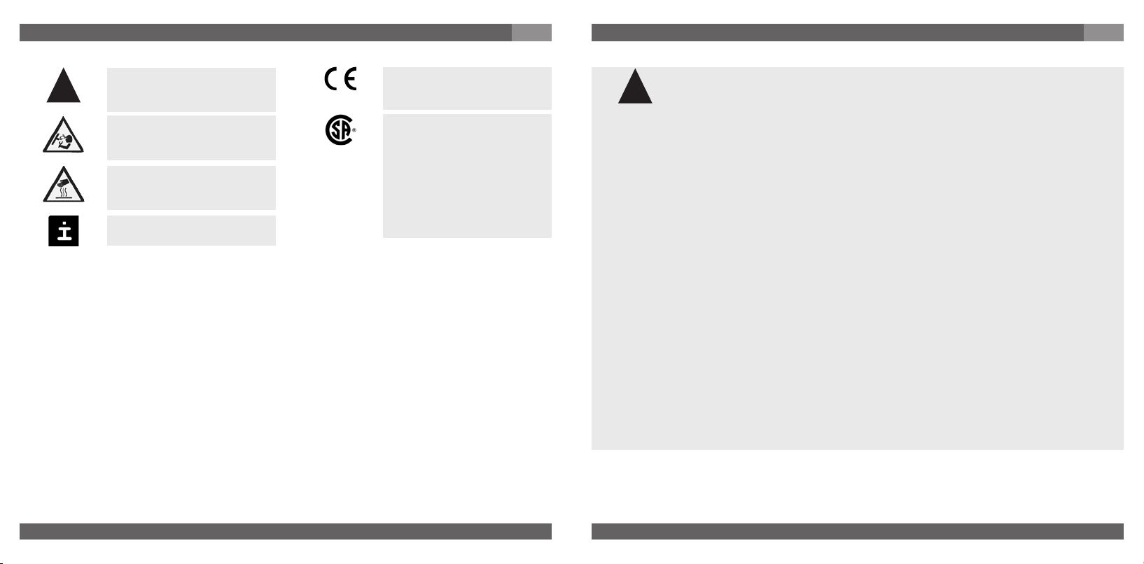
The product complies with
the applicable European
directives.
CSA
Canadian Standard Asso-
ciation
The product was tested and
certified by CSA Internati-
onal. It complies with the
applicable Canadien stan-
dards on safety.
Potential danger of life or
of severe injuries due to
catapulting parts.
Potential danger of burns
due to hot surfaces.
5. For your safety
5. For your safety
GB
Select the appropriate pressure transmitter with regard to scale range,
performance and specific measurement conditions prior to installing and
starting the instrument.
Observe the relevant national regulations (e.g.: EN 50178) and observe the
applicable standards and directives for special applications (e.g. with
dangerous media such as acetylene, flammable gases or liquids and toxic
gases or liquids and with refrigeration plants or compressors). If you do not
observe the appropriate regulations, serious injuries and/or damage
can occur!
Open pressure connections only after the system is without pressure!
Please make sure that the pressure transmitter is only used within the overload threshold
limit all the time!
Observe the ambient and working conditions outlined in section 7 „Technical data”.
Observe the technical data for the use of the pressure transmitter in connection with
aggressive / corrosive media and for the avoidance of mechanical hazards.
Ensure that the pressure transmitter is only operated in accordance with the provisions i.e.
as described in the following instructions.
Do not interfere with or change the pressure transmitter in any other way than described in
these operating instructions.
Remove the pressure transmitter from service and mark it to prevent it from being used
again accidentally, if it becomes damaged or unsafe for operation
Take precautions with regard to remaining media in removed pressure transmitter.
Remaining media in the pressure port may be hazardous or toxic!
Have repairs performed by the manufacturer only.
Open circuit before removing connector / cover.
Information about material consistency against corrosion and diffusion can be found in our
WIKA-Handbook, 'Pressure and Temperature Measurement'.
!
Warning
Caution
Warning
!
Warning
1604457.14 GB/D/F/E 12/2009
6
WIKA Operating instructions/Betriebsanleitung/Mode d'emploi/Instrucciones de servicio S-10, S-11
1604457.14 GB/D/F/E 12/2009
7
WIKA Operating instructions/Betriebsanleitung/Mode d'emploi/Instrucciones de servicio S-10, S-11
6. Packaging / 7. Starting, operation
GB
6. Packaging
Has everything been supplied?
Check the scope of supply:
Completely assembled pressure transmitters.
With flush version (S-11) including pre-assembled sealings and protection cap.
Inspect the pressure transmitter for possible damage during transportation. Should
there be any obvious damage, inform the transport company and WIKA without delay.
Keep the packaging, as it offers optimal protection during transportation (e.g. chan-
ging installation location, shipment for repair).
Ensure that the pressure connection thread and the connection contacts will not be
damaged.
In order to protect the diaphragm, the pressure connection of the instrument S-11 is provided
with a special protection cap.
Remove this protection cap by hand only just before installing the pressure transmitter
in order to prevent any damage to the diaphragm or the thread.
Keep the protection cap of the pressure connection thread and the diaphragm for
later storage or transport.
Mount the protection cap when removing and transporting the instrument.
7. Starting, operation
Required tools: wrench (flats 27), screw driver
Diaphragm test for your safety
It is necessary that before starting the pressure transmitter you test the diaphragm visually, as
this is a safety-relevant component.
Pay attention to any liquid leaking out, for this points to a diaphragm
damage.
Check the diaphragm visually for any damage (S-11).
Use the pressure transmitter only if the diaphragm is undamaged.
Use the pressure transmitter only if it is in a faultless condition as far as the
safety-relevant features are concerned.
7. Starting, operation
GB
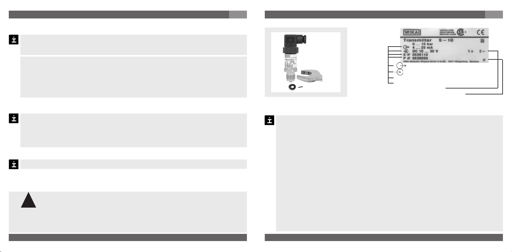
Signal
Power Supply
Serial No.
Product No.
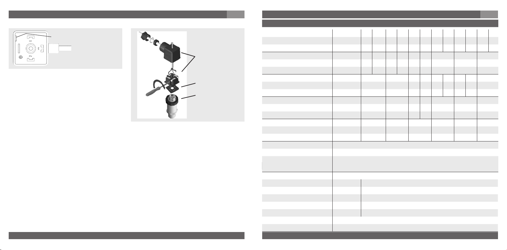
PIN assignment
Coded manufacture date
S #
Generally the serial number on the product label applies. If there is no serial number on the product label,
the number on the hexagon will apply.
max.
50 Nm
Sealing
Mechanical connection
Product label (example)
Remove the protection cap by hand only just before installation and absolutely avoid
any damage to the diaphragm during installation as well (S-11).
For Model S-10 you have to provide for a sealing element; exceptions are instruments
with self-sealing threads (e.g. NPT thread). For Model S-11 the sealing is included in
delivery.
Please refer to our data sheet “Pressure gauge sealing washers AC 09.08” in WIKA’s
product catalog Pressure and Temperature Measurement or our website
www.wika.de for details about sealing washers.
When mounting the instrument, ensure that the sealing faces of the instrument and
the measuring point are clean and undamaged.
Screw in or unscrew the instrument only via the flats using a suitable tool and the
prescribed torque. The appropriate torque depends on the dimension of the pressure
connection and on the sealing element used (form/material). Do not use the case as
working surface for screwing in or unscrewing the instrument.
When screwing the transmitter in, ensure that the threads are not jammed.
For tapped holes and welding sockets please see Technical Information IN 00.14 for
download at www.wika.de - Download
P #
!
Warning
1604457.14 GB/D/F/E 12/2009
8
WIKA Operating instructions/Betriebsanleitung/Mode d'emploi/Instrucciones de servicio S-10, S-11
1604457.14 GB/D/F/E 12/2009
9
WIKA Operating instructions/Betriebsanleitung/Mode d'emploi/Instrucciones de servicio S-10, S-11
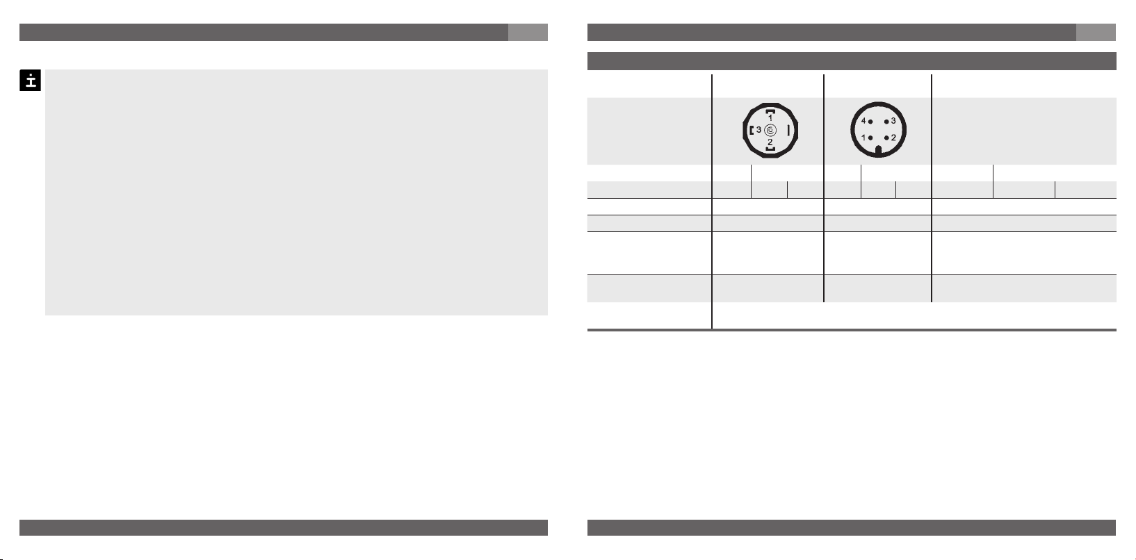
Electrical connections
L-connector DIN
175301-803 A
Circular connector
M12x1
Flying leads with 1.5 m of cable
2-wire U+ = 1 U- = 2 U+ = 1 U- = 3 U+ = brown U- = green
3-wire U+ = 1 U- = 2 S+ = 3 U+ = 1 U- = 3 S+ = 4 U+ = brown U- = green S+ = white
Cable screen grey
Wire gauge up to max. 1.5 mm
2
- 0.5 mm
2
(AWG 20)
Diameter of cable
6-8 mm
(ship approval:
10-14 mm)
- 6.8 mm
Ingress protection per
IEC 60 529
IP 65 IP 67 IP 67 or IP 68
The ingress protection classes specified only apply while the pressure transmitter is
connected with female connectors that provide the corresponding ingress protection.
Connect the instrument to earth via the pressure connection.
For transmitter with voltage output signal: Operate the pressure transmitter with a
shielded cable and earth the shield at least on one side of the cable, if the cable is
longer than 30 m or if it is run outside of the building.
For North America: The connection shall be made to „Class 2 Circuits“ or „Class 2
Power Units“ according to CEC (Canadian Electrical Code) or NEC (National Electrical
Code).
Ingress protection per IEC 60529 (The ingress protection classes specified only apply
while the pressure transmitter is connected with female connectors that provide the
corresponding ingress protection).
Ensure that the cable diameter you select fits to the cable gland of the connector.
Ensure that the cable gland of the mounted connector is positioned correctly and
that the sealings are available and undamaged. Tighten the threaded connection and
check the correct position of the sealings in order to ensure the ingress protection.
Please make sure that the ends of cables with flying leads do not allow any ingress of
moisture.
Electrical connection
7. Starting, operation
GB
7. Starting, operation
GB
1604457.14 GB/D/F/E 12/2009
10
WIKA Operating instructions/Betriebsanleitung/Mode d'emploi/Instrucciones de servicio S-10, S-11
1604457.14 GB/D/F/E 12/2009
11
WIKA Operating instructions/Betriebsanleitung/Mode d'emploi/Instrucciones de servicio S-10, S-11
Specifications Model S-10, S-11
Materials
Wetted parts (Other materials see WIKA diaphragm seal program)
Pressure connection» 316 Ti, S-11: O-ring: NBR
3)
{FPM/FKM}
Pressure sensor» 316 Ti (as of 40 bar / 600 psi 13-8 PH)
Case Stainless steel
Internal transmission fluid
4)
Synthetic oil
3)
O-ring made of FPM/FKM for model S-11 with integrated cooling element.
4)
Not for model S-10 with pressure ranges > 25 bar / 300 psi
Specifications Model S-10, S-11
Pressure ranges bar 0.1 0.16 0.25 0.4 0.6 1 1.6 2.5 4 6 10 16
Over pressure safety bar 1 1.5 2 2 4 5 10 10 17 35 35 80
Burst pressure bar 2 2 2.4 2.4 4.8 6 12 12 20.5 42 42 96
Pressure ranges bar 25 40 60 100 160 250 400 600 1000
1)
Over pressure safety bar 50 80 120 200 320 500 800 1200 1500
Burst pressure bar 96 400 550 800 1000 1200 1700
2)
2400
2)
3000
Pressure ranges psi 50 INWC 100 INWC 5 10 15 25 30 60 100
Over pressure safety psi 14.5 29 29 58 72 145 145 240 500
Burst pressure psi 29 35 35 69 87 170 170 290 600
Pressure ranges psi 200 300 500 600 1000 1500 2000
Over pressure safety psi 1160 1160 1160 1160 1740 2900 4600
Burst pressure psi 1390 1390 5800 5800 7970 11,600 14,500
Pressure ranges psi 3000 5000 8000 10,000
1)
15,000
1)
Over pressure safety psi 7200 11,600 17,400 17,400 21,750
Burst pressure psi 17,400 24,650
2)
34,800
2)
34,800 43,500
{Vacuum, gauge pressure, compound range, absolute pressure are available}.
1)
Only model S-10.
2)
For model S-11: The value specified in the table applies only when sealing is
realised with the sealing ring underneath the hex. Otherwise max. 1,500 bar /
21,000 psi applies.
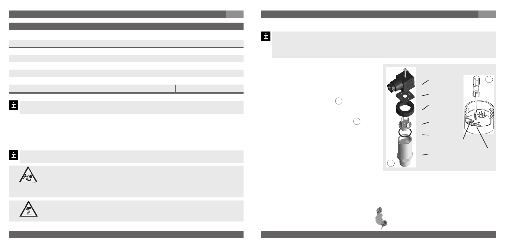
(D) Mounting hole
1. Loosen the screw (1).
2. Loosen the cable gland (2).
3. Pull the angle housing (5), with the
terminal block (6) inside, away from the
instrument.
4. Using the head of a small screwdriver in
the mounting hole (D), lever the terminal
block (6) out of the angle housing (5).
In order not to damage the sealing of the angle housing, do not try to push the terminal
block (6) out using the screw hole (1) or the cable gland (2).
5. Ensure that the conductor outer diameter you select is matched to the angle housing’s
cable gland. Slide the cable through the cable gland nut (2), washer (3), gland seal (4) and
angle housing (5).
6. Connect the flying leads to the screw terminals on the terminal block (6) in accordance
with the pin-assignment drawing.
7. Press the terminal block (6) back into the angle housing (5).
8. Tighten the cable gland (2) around the cable. Make sure that the sealing isn’t damaged
and that the cable gland and seals are assembled correctly in order to ensure ingress
protection.
9. Place the flat, square gasket over the connection pins on the top of the instrument
housing.
10. Slide the terminal block (6) onto the connection pins.
11. Secure the angle housing (5) and terminal block (6) to the instrument with the screw (1).
Assembly of L-connector DIN EN 175301-803 Form A
(6)
(5)
(1)
(2)
(3)
(4)
Clamping nut,
Male connector,
Case with
pressure connection
Sealing
Female
connector
7. Starting, operation
GB
7. Starting, operation
GB

1604457.14 GB/D/F/E 12/2009
12
WIKA Operating instructions/Betriebsanleitung/Mode d'emploi/Instrucciones de servicio S-10, S-11
1604457.14 GB/D/F/E 12/2009
13
WIKA Operating instructions/Betriebsanleitung/Mode d'emploi/Instrucciones de servicio S-10, S-11
Specifications Model S-10, S-11
Power supply U+ UB in VDC 10 < U+ ≤ 30 (14 … 30 with signal output 0 … 10 V)
Signal output and RA in Ohm 4 … 20 mA, 2-wire RA ≤ (U+ – 10 V) / 0.02 A
maximum ohmic load RA 0 … 20 mA, 3-wire RA ≤ (U+ – 3 V) / 0.02 A
0 … 5 V, 3-wire R
A > 5000
0 … 10 V, 3-wire R
A > 10000
{Other signal output on request}
Adjustability zero/span %
± 5 using potentiometers inside the instrument
Response time (10 ... 90 %) ms
≤ 1 (≤ 10 ms at medium temperatures below<-30 °C (-22°F) for pres-
sure ranges up to 25 bar / 300 psi or with flush diaphragm (S-11).
Insulation voltage VDC 500
5)
5)
Use NEC Class 02 power supply (low voltage and low current max. 100 VA even
under fault conditions)
Accuracy % of span
≤ 0.25 {0.125}
6)
(BFSL)
≤ 0.5
7)
{0.25}
6) 7)
6)
Accuracy { } for pressure ranges ≥ 0.25 bar (100 INWC).
7)
Including non-linearity, hysteresis, zero point and full scale error (corresponds to
error of measurement per IEC 61298-2).
Adjusted in vertical mounting position with lower pressure connection.
Non-linearity % of span
≤ 0.2 (BFSL) according to IEC 61298-2
Non-repeatability % of span
≤ 0.1 according to IEC 61298-2
1-year stability % of span
≤ 0.2 (at reference conditions)
Permissible temperature of
Medium -30 ... +100 °C -22 ... +212 °F
{-40 ... +125 °C} {-40 ... +257 °F}
S-11 with cooling element» {-20 ... +150 °C} {-4 ... +302 °F}
Ambience -20 ... +80 °C -4 ... +176 °F
S-11 with cooling element» -20 ... +80 °C -4 ... +176 °F
Specifications Model S-10, S-11
Storage -40 ... +100 °C -40 ... +212 °F
S-11 with cooling element» -20 ... +100 °C -4 ... +212 °F
Rated temperature range 0 ... +80 °C 32 ... +176 °F
Temperature coefficients within
rated temperature range
Mean TC of zero % of span
≤ 0.2 / 10 K (< 0.4 for pressure range ≤ 0.25 bar (100 INWC))
Mean TC of range % of span
≤ 0.2 / 10 K
CE- conformitiy
Pressure equipment directive 97/23/EC
EMC directive
2004/108/EC, EN 61 326 Emission (Group 1, Class B) and Immunity
(industrial locations)
Shock resistance g 1000 according to IEC 60068-2-27 (mechanical shock)
Vibration resistance g 20 according to IEC 60068-2-6 (vibration under resonance)
Wiring protection
Short-circuit proofness S+ towards U-
Reverse polarity protection U+ towards U-
Weight kg
Approx. 0.2 (approx. 0.4 lb)
Approx. 0.3 with option accuracy 0.25% of span due to longer case
7. Starting, operation
GB
7. Starting, operation
GB
{ } Items in curved brackets are optional extras for additional price.
1604457.14 GB/D/F/E 12/2009
14
WIKA Operating instructions/Betriebsanleitung/Mode d'emploi/Instrucciones de servicio S-10, S-11
1604457.14 GB/D/F/E 12/2009
15
WIKA Operating instructions/Betriebsanleitung/Mode d'emploi/Instrucciones de servicio S-10, S-11
Specifications Oxygen version of model S-10
Pressure ranges bar As of 0 ... 0.1 / 50 INWC
Type of pressure Gauge pressure
Materials
Wetted parts 316 Ti (up to 40 bar / 600 psi F 1058)
Internal transmission fluid
1)
Halocarbon oil
1)
Not for model with pressure ranges > 25 bar / 300 psi
Permissible temperature of
Medium -20 ... +60 °C -4 ... +140 °F
Functional test
Open pressure connections only after the system is without pressure!
Observe the ambient and working conditions outlined in section 7 „Technical
data".
Please make sure that the pressure transmitter is only used within the over-
load threshold limit at all times!
The output signal must be proportional to the pressure. If not, this might point to a
damage of the diaphragm. In that case refer to chapter 10 „Troubleshooting“.
When touching the pressure transmitter, keep in mind that the surfaces of
the instrument components might get hot during operation.
7. Starting, operation
GB
Z = Zero
S = Span
Female
connector
Sealing
Clamping
nut
Male
connector
Sealing
Case with
pressure
connection
Recommended recalibration cycle: yearly
For further information (+49) 9372/132-295
8. Adjustment of zero point / span (only for pressure transmitter with clamping nut)
A
B
We do not recommend to adjust the span potentiometer. It is used for adjustment ex
factory and should not be adjusted by you unless you have adequate calibration equip-
ment at your disposal (at least three times more accurate than the instrument being
tested).
8. Adjustment of zero point / span
GB
Make sure wires are not cut or pinche
during disassembly and reassembly of
the connector.
Remove the female connector. Open
the pressure transmitter by detaching
the clamping nut (see Fig. A ). Carefully
remove the male connector from the
case.
Adjust the zero point (Z) (see Fig. B ) by
generating the lower limit of the pressure
range.
Adjust the span (S) by generating the
higher limit of the pressure range.
Check the zero point.
If the zero point is incorrect, repeat
procedure as required.
Reassemble the instrument carefully.
Make sure all sealings and o-rings are
not damaged and correctly installed to
assure the rated moisture ingress protec-
tion.
When designing your plant, take into account that the stated values (e.g.burst pressure,
over pressure safety) apply depending on the material, thread and sealing element used.
Warning
Caution
1604457.14 GB/D/F/E 12/2009
16
WIKA Operating instructions/Betriebsanleitung/Mode d'emploi/Instrucciones de servicio S-10, S-11
1604457.14 GB/D/F/E 12/2009
17
WIKA Operating instructions/Betriebsanleitung/Mode d'emploi/Instrucciones de servicio S-10, S-11
Failure Possible cause Procedure
No output signal Cable break Check connections and cable
No/incorrect voltage supply or current
spike
Adjust the voltage supply to correspond
with the Operating Instructions *)
No/False output signal
Incorrectly wired (e.g. Connected as
2-wire instead of 3-wire system)
Follow pin assignment (see Instrument
Label / Operating Instructions)
Output signal unchanged after change
in pressure
Mechanical overload through over-
pressure
Replace instrument; if failure reoccurs,
consult the manufacturer *)
Signal span dropping off/too small
Mechanical overload through over-
pressure
Replace instrument; if failure reoccurs,
consult the manufacturer *)
Diaphragm is damaged, e.g. through
impact, abrasive/agressive media;
corrosion of diaphragm/pressure
connector; transmission fluid missing.
Contact the manufacturer and replace
the instrument
Seal/Sealing face damaged/conta-
minated, seal mounted incorrectly,
threads crossed
Clean the seal/sealing face, possibly
replace the seal.
Signal span erratic / incorrect
Electromagnetic interference source in
the vicinity, e.g. inverter drive
Shield the device; shield the cables;
remove the interference source
Working temperature too high/too low
Ensure permissible temperatures as per
the Operating Instructions
Instrument not grounded Ground instrument
Violent fluctuations in the process
media pressure
Damping; consult with manufacturer
Abnormal zero point signal Working temperature too high/too low
Ensure permissible temperatures as per
the Operating Instructions
Abnormal mounting position
Correct the zero point through the
potentiometer, control panel or software
Overload limits exceeded
Ensure permissible overload limits are
observed (see Operating Instructions) *)
9. Maintenance, accessories /10. Trouble shooting
GB
9. Maintenance, accessories
Accessories
For details about the accessories (e. g. connectors), please refer to WIKA‘s price list, WIKA‘s
product catalog on CD or or contact our sales department.
10. Trouble shooting
Open pressure connections only after the system is without pressure!
WIKA pressure transmitters require no maintenance.
Have repairs performed by the manufacturer only.
Do not insert any pointed or hard objects into the pressure port for cleaning to prevent
damage to the diaphragm of the pressure connection.
Take precautions with regard to remaining media in removed pressure trans-
mitters. Remaining media in the pressure port may be hazardous or
toxic!
Remove the pressure transmitter from service and mark it to prevent it from
being used again accidentally, if it becomes damaged or unsafe for opera-
tion.
Have repairs performed by the manufacturer only.
Please verify in advance if pressure is being applied (valves/ ball valve etc. open) and if the
right voltage supply and the right type of wiring (2-wire/ 3-wire) has been chosen?
10. Trouble shooting
GB
In case of unjustified reclamation we charge the reclamation handling expenses.
*) Make sure that after the setting the unit is working properly. In case the error continues to exist send in the instrument for reparation (or
replace the unit).
Warning
!
Warning

1604457.14 GB/D/F/E 12/2009
18
WIKA Operating instructions/Betriebsanleitung/Mode d'emploi/Instrucciones de servicio S-10, S-11
1604457.14 GB/D/F/E 12/2009
19
WIKA Operating instructions/Betriebsanleitung/Mode d'emploi/Instrucciones de servicio S-10, S-11
If the problem persists, contact our sales department.
USA, Canada
If the problem continues, contact WIKA or an authorized agent for assistance. If the pres-
sure transmitter must be returned obtain an RMA (return material authorization) number and
shipping instructions from the place of purchase. Be sure to include detailed information about
the problem. Pressure transmitters received by WIKA without a valid RMA number will not be
accepted.
Process material certificate (Contamination declaration for returned goods)
Purge / clean dismounted instruments before returning them in order to protect our employees
and the environment from any hazard caused by adherent remaining media.
Service of instruments can only take place safely when a Product Return Form has been
submitted and fully filled-in. This Return Form contains information on all materials with which
the instrument has come into contact, either through installation, test purposes, or cleaning.
You can find the Product Return Form on our internet site (www.wika.de / www.wika.com).
10. Trouble shooting / 11. Storage, disposal
GB
11. Storage, disposal
When storing or disposing of the pressure transmitter, take precautions with
regard to remaining media in removed pressure transmitters. We recom-
mend cleaning the transmitter properly and carefully. Remaining media in
the pressure port may be hazardous or toxic!
Mount the protection cap when storing the pressure transmitter in order to prevent any
damage to the diaphragm (S-11).
Dispose of instrument components and packaging materials in accordance with the
respective waste treatment and disposal regulations of the region or country to which
the instrument is supplied.
Storage
Disposal
WIKA reserves the right to alter these technical specifications.
1. Wichiges zu Ihrer Information / 2. Schneller Überblick
D
Ihre erforderlichen Kenntnisse
Montieren und nehmen Sie das Druckmessgerät nur in Betrieb, wenn Sie mit den zutreffenden
landesspezifischen Richtlinien vertraut sind und die entsprechende Qualifikation besitzen. Sie
müssen mit den Kenntnissen von Mess- und Regeltechnik sowie elektrischen Stromkreisen
vertraut sein, da das Druckmessgerät ein „elektrisches Betriebsmittel“ nach EN 50178 ist. Je
nach Einsatzbedingung müssen Sie über entsprechendes Wissen verfügen, z. B. über agres-
sive Medien bzw. hohe Drücke.
1. Wichtiges zu Ihrer Information
Lesen Sie diese Betriebsanleitung vor Montage und Inbetriebnahme des Druckmessgerätes.
Bewahren Sie die Betriebsanleitung an einem für alle Benutzer jederzeit zugänglichen Ort auf.
Die nachfolgenden Einbau- und Betriebshinweise haben wir mit Sorgfalt zusammengestellt.
Es ist jedoch nicht möglich, alle erdenklichen Anwendungsfälle zu berücksichtigen. Sollten Sie
Hinweise für Ihre spezielle Aufgabenstellung vermissen, können Sie hier weitere Informationen
finden:
Über unsere Internet-Adresse www.wika.de / www.wika.com
Die Bezeichnung des zugehörigen Datenblattes ist PE 81.01
Anwendungsberater: (+49) 9372/132-295
Bestimmungsgemäße Produktverwendung
Verwenden Sie den Druckmessumformer, um Druck in ein elektrisches Signal zu wandeln.
Bei Sondertypennummer, z.B. S-10000 oder S-11000, beachten Sie die Spezifikationen
gemäß Lieferschein.
Wird die Seriennummer und/oder der 2D-Code auf dem Sechskant unleserlich (z. B. durch
mechanische Beschädigung oder Übermalen), ist eine Rückverfolgbarkeit nicht mehr möglich.
Die in der Betriebsanleitung beschriebenen WIKA-Druckmessgeräte werden nach den
neuesten Erkenntnissen konstruiert und gefertigt. Alle Komponenten unterliegen während der
Fertigung strengen Qualitäts- und Umweltkriterien. Unser Umweltmanagementsystem ist nach
DIN EN ISO 14001 zertifiziert.
2. Der schnelle Überblick für Sie
Wollen Sie sich einen schnellen Überblick verschaffen, lesen Sie Kapitel 3, 5, 7 und 11. Dort
erhalten Sie kurze Hinweise zu Ihrer Sicherheit und wichtige Informationen über Ihr Produkt
und zur Inbetriebnahme. Lesen Sie diese unbedingt.
!
Warning
1604457.14 GB/D/F/E 12/2009
20
WIKA Operating instructions/Betriebsanleitung/Mode d'emploi/Instrucciones de servicio S-10, S-11
1604457.14 GB/D/F/E 12/2009
21
WIKA Operating instructions/Betriebsanleitung/Mode d'emploi/Instrucciones de servicio S-10, S-11
3. Zeichenerklärungen, Abkürzungen / 4. Funktion
D
2-Leiter Zwei Anschlussleitungen dienen zur Spannungsversorgung.
Der Speisestrom ist das Mess-Signal.
3-Leiter Zwei Anschlussleitungen dienen zur Spannungsversorgung.
Eine Anschlussleitung dient für das Mess-Signal.
U+ Positiver Versorgungsanschluss
U- Negativer Versorgungsanschluss
S+ Positiver Messanschluss
4. Funktion
S-10: Druckanschluss mit innenliegender Membran (Standardausführung).
S-11: Druckanschluss mit frontbündiger Membrane für hochviskose oder kristallisie
rende Medien, die die Bohrung des Druckanschlusses zusetzen können.
Funktion Mittels Sensorelement und unter Zuführung von Hilfsenergie wird über die Verfor-
mung einer Membran der anstehende Druck in Ihrer Anwendung in ein verstärktes standardi-
siertes elektrisches Signal umgewandelt. Dieses elektrische Signal verändert sich proportional
zum Druck und kann entsprechend ausgewertet werden.
3. Zeichenerklärungen, Abkürzungen
Mögliche Gefahr für Ihr
Leben oder schwerer
Verletzungen.
Hinweis, wichtige Informa-
tion, Funktionsstörung.
Das Produkt stimmt mit den
zutreffenden europäischen
Richtlinien überein.
CSA
Canadian Standard Asso-
ciation
Das Produkt wurde durch
CSA International geprüft
und zerti-fiziert. Es stimmt
überein mit den anwend-
baren kanadischen Normen
zur Sicherheit.
Mögliche Gefahr für Ihr
Leben oder schwerer Verlet-
zungen durch wegschleu-
dernde Teile.
Mögliche Gefahr von
Verbrennungen durch
heisse Oberflächen.
5. Zu Ihrer Sicherheit
D
5. Zu Ihrer Sicherheit
Angaben zu Korrosions- bzw. Diffusionsbeständigkeit der Gerätewerkstoffe entnehmen Sie
bitte unserem WIKA-Handbuch zur Druck- und Temperaturmesstechnik.
Wählen Sie das richtige Druckmessgerät hinsichtlich Messbereich, Ausfüh-
rung und spezifischen Messbedingungen vor Montage oder Inbetriebnahme.
Halten Sie die entsprechenden landesspezifischen Vorschriften ein (z. B.:
EN 50178) und beachten Sie bei speziellen Anwendungen die geltenden
Normen und Richtlinien (z. B. bei gefährlichen Messstoffen wie Acetylen,
brennbaren oder giftigen Stoffen sowie bei Kälteanlagen und Kompres-
soren). Wenn Sie die entsprechenden Vorschriften nicht beachten,
können schwere Körperverletzungen und Sachschäden entstehen!
Öffnen Sie Anschlüsse nur im drucklosen Zustand!
Betreiben Sie das Druckmessgerät immer innerhalb des Überlastgrenzbereiches!
Beachten Sie die Betriebsparameter gemäß Punkt 7 „Technische Daten“.
Beachten Sie die Technischen Daten zur Verwendung des Druckmessgerätes in Verbin-
dung mit agressiven / korrosiven Medien und zur Vermeidung von mechanischen Gefähr-
dungen.
Stellen Sie sicher, dass das Druckmessgerät nur bestimmungsgemäß -also wie in der
folgenden Anleitung beschrieben- betrieben wird.
Unterlassen Sie unzulässige Eingriffe und Änderungen am Druckmessgerät, welche nicht
in dieser Betriebsanleitung beschrieben sind.
Setzen Sie das Druckmessgerät außer Betrieb und schützen Sie es gegen versehentliche
Inbetriebnahme, wenn Sie Störungen nicht beseitigen können.
Ergreifen Sie Vorsichtsmaßnahmen für Messstoffreste in ausgebauten Druckmess-
geräten. Messstoffreste können zur Gefährdung von Menschen, Umwelt und Einrich-
tung führen!
Lassen Sie Reparaturen nur vom Hersteller durchführen
Öffnen Sie den Stromkreis, bevor Sie den Stecker / Deckel abnehmen.
!
Warnung
Vorsicht
Warnung
!
Warnung
 Loading...