


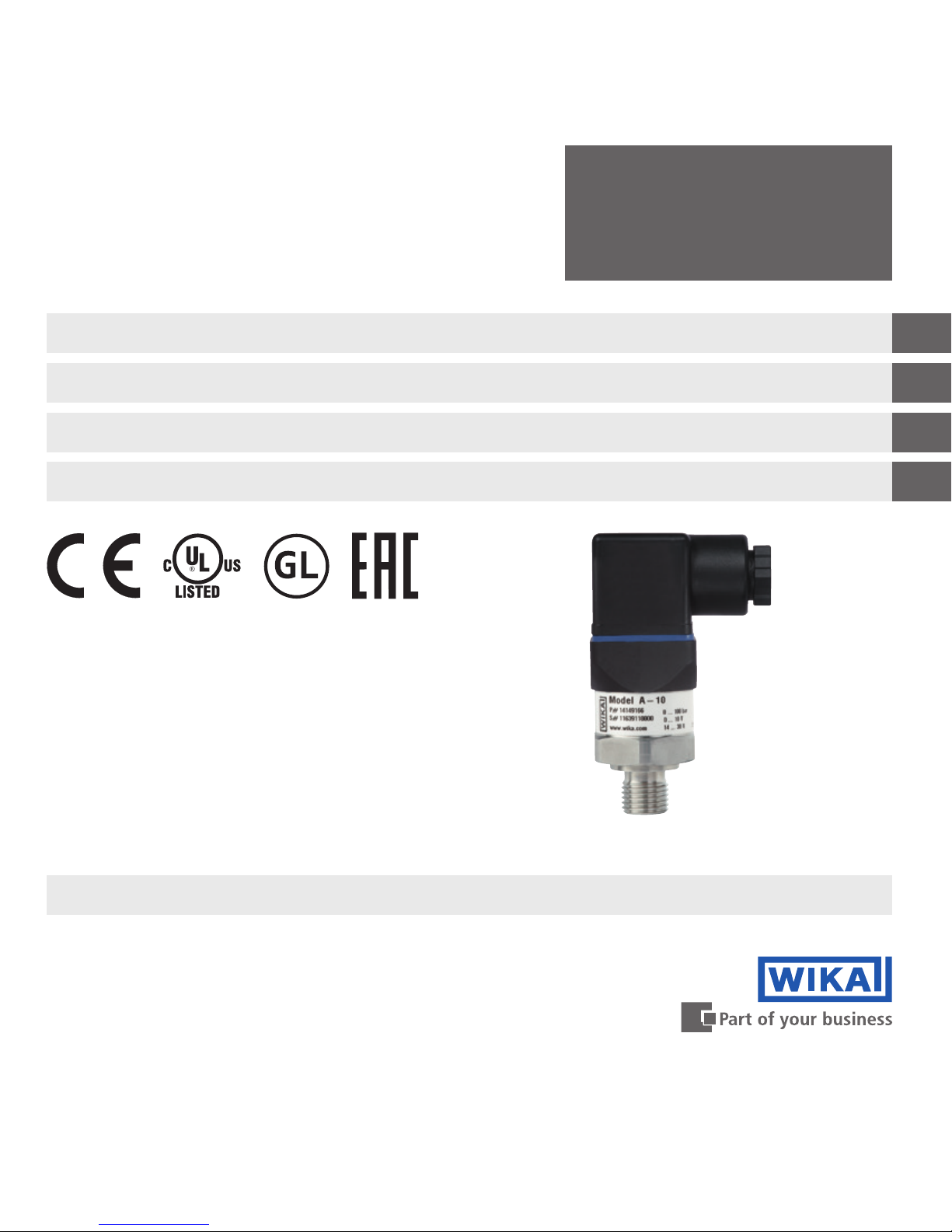
A-10
Operating instructions
Betriebsanleitung
Mode d'emploi
Manual de instrucciones
EN
DE
FR
ES
Druckmessumformer, Typ A-10
Pressure transmitter model A-10
Pressure transmitter, model A-10
Transmetteur de pression, type A-10
Transmisor de presión, modelo A-10

2 WIKA operating instructions pressure transmitter, model A-10
EN
DE
11218720.15 07/2018 EN/DE/FR/ES
FR
ES
© 2010 WIKA Alexander Wiegand SE & Co. KG
All rights reserved. / Alle Rechte vorbehalten.
WIKA® is a registered trademark in various countries.
WIKA® ist eine geschützte Marke in verschiedenen Ländern.
Prior to starting any work, read the operating instructions!
Keep for later use!
Vor Beginn aller Arbeiten Betriebsanleitung lesen!
Zum späteren Gebrauch aufbewahren!
Lire le mode d‘emploi avant de commencer toute opération !
A conserver pour une utilisation ultérieure !
¡Leer el manual de instrucciones antes de comenzar cualquier trabajo!
¡Guardar el manual para una eventual consulta!
Betriebsanleitung Typ A-10 Seite 25 - 46
Operating instructions model A-10 Page 3 - 24
Mode d‘emploi type A-10 Page 47 - 68
Manual de instrucciones modelo A-10 Página 69 - 91

3WIKA operating instruction pressure transmitter, model A-10
EN
11218720.15 07/2018 EN/DE/FR/ES
Contents
Declarations of conformity can be found online at www.wika.com
Contents
1. General information 4
2. Design and function 5
3. Safety 6
4. Transport, packaging and storage 8
5. Commissioning, operation 9
6. Faults 12
7. Maintenance and cleaning 14
8. Dismounting, return and disposal 15
9. Specications 17

4 WIKA operating instruction pressure transmitter, model A-10
EN
11218720.15 07/2018 EN/DE/FR/ES
1. General information
1. General information
■
The instrument described in the operating instructions has been designed and manufactured using state-of-theart technology. All components are subject to stringent quality and environmental criteria during production. Our
management systems are certied to ISO 9001 and ISO 14001.
■
These operating instructions contain important information on handling the instrument. Working safely requires that
all safety instructions and work instructions are observed.
■
Observe the relevant local accident prevention regulations and general safety regulations for the instrument’s range
of use.
■
The operating instructions are part of the product and must be kept in the immediate vicinity of the instrument and
readily accessible to skilled personnel at any time. Pass the operating instructions on to the next operator or owner
of the instrument.
■
Skilled personnel must have carefully read and understood the operating instructions prior to beginning any work.
■
The general terms and conditions contained in the sales documentation shall apply.
■
Subject to technical modications.
■
Further information:
- Internet address: www.wika.de / www.wika.com
- Relevant data sheet: PE 81.60
- Application consultant: Tel.: +49 9372 132-0
Fax: +49 9372 132-406
info@wika.com
5WIKA operating instruction pressure transmitter, model A-10
EN
11218720.15 07/2018 EN/DE/FR/ES
2. Design and function
2. Design and function
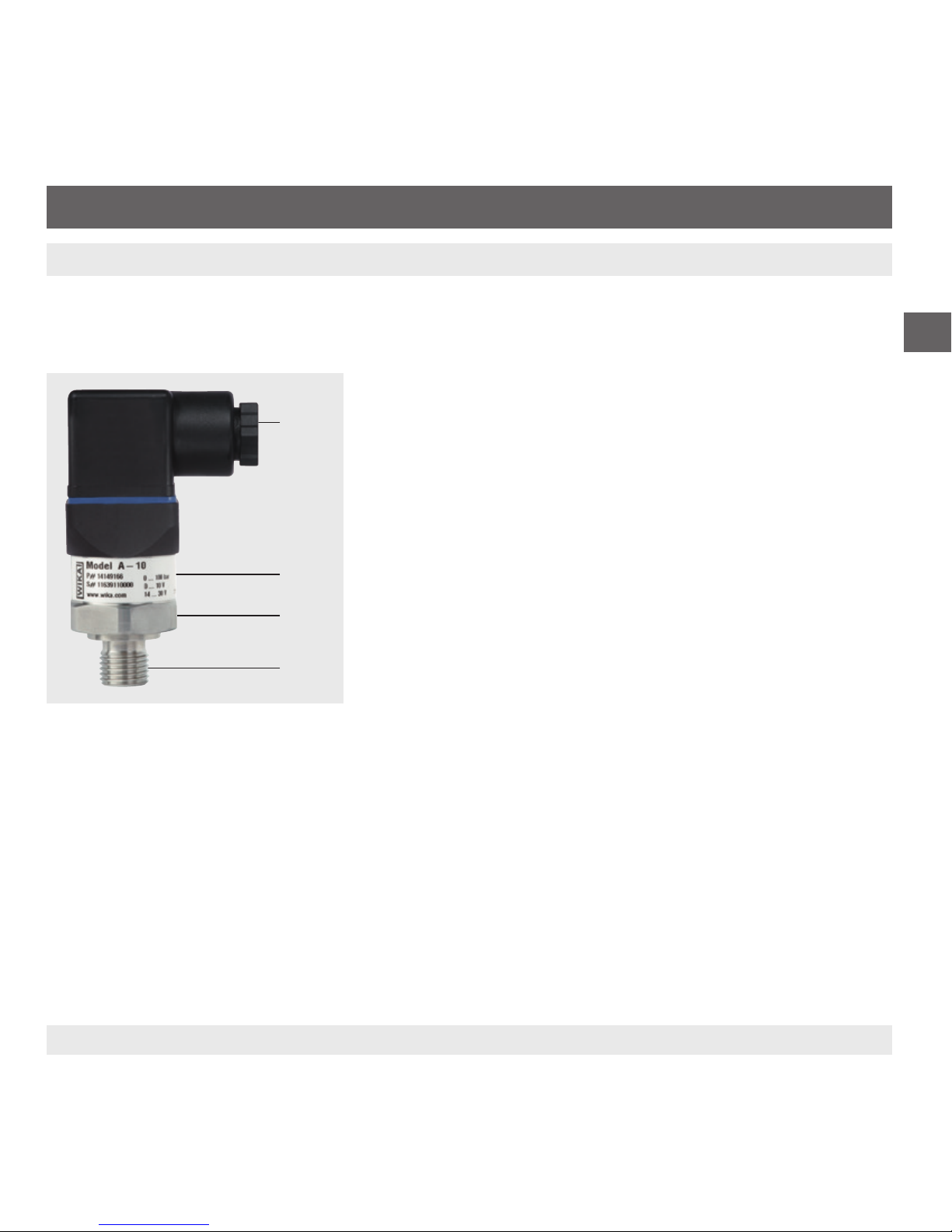
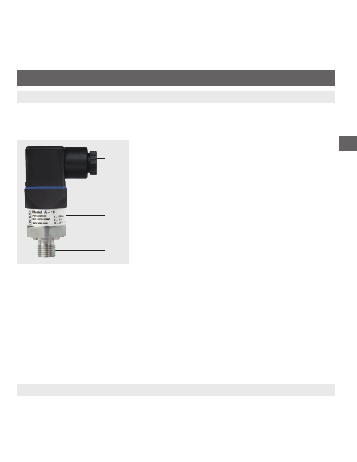
2.1 Overview
Electrical connection (depending on version)
Case; product label
Process connection, spanner flats
Process connection, thread
2.2 Scope of delivery
■
Pressure transmitter
■
Operating instructions
Cross-check scope of delivery with delivery note.
6 WIKA operating instruction pressure transmitter, model A-10
EN
11218720.15 07/2018 EN/DE/FR/ES
3. Safety
3. Safety
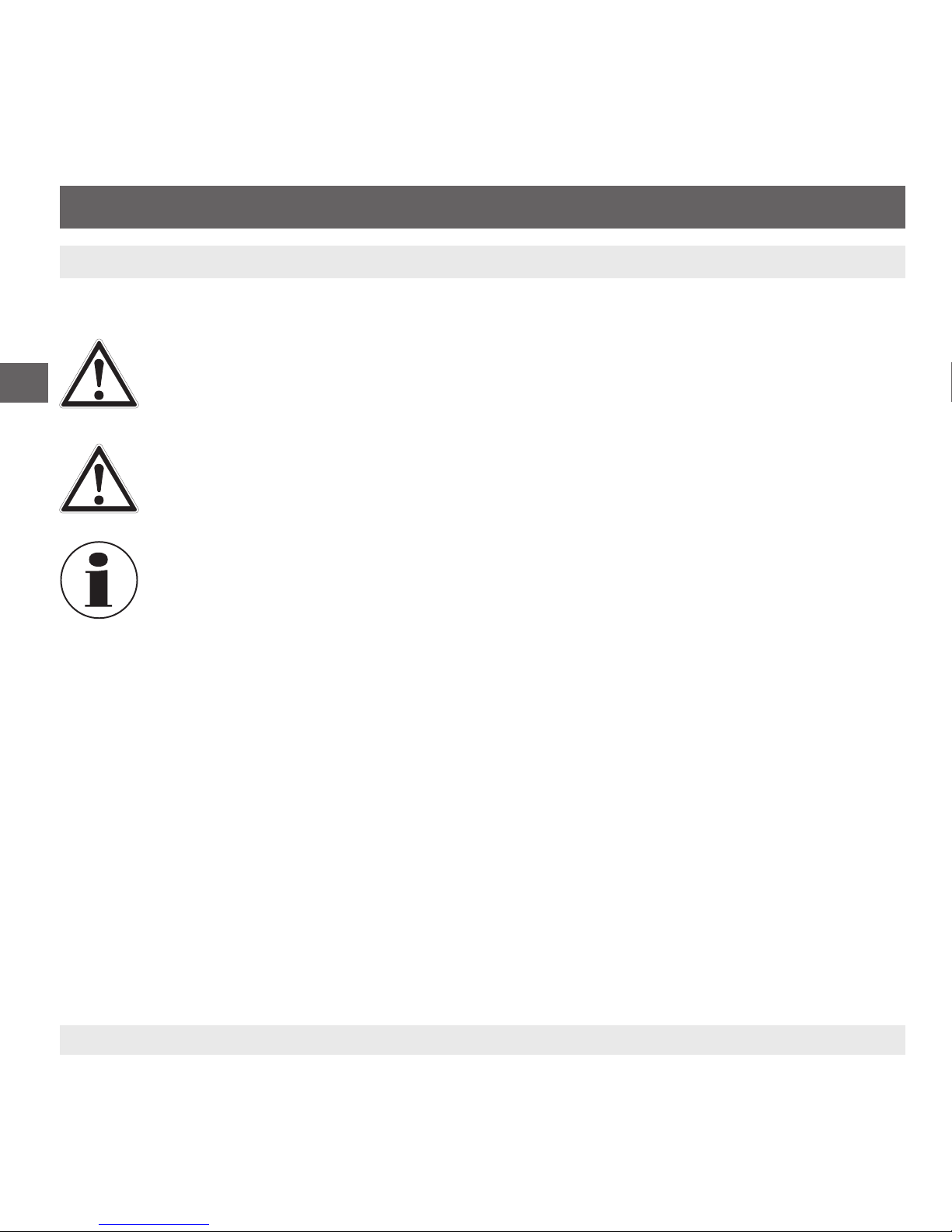
3.1 Explanation of symbols
WARNING!
... indicates a potentially dangerous situation that can result in serious injury or death, if not avoided.
CAUTION!
... indicates a potentially dangerous situation that can result in light injuries or damage to property or the
environment, if not avoided.
Information
... points out useful tips, recommendations and information for ecient and trouble-free operation.
3.2 Intended use
The pressure transmitter is used for measuring pressure. The measured pressure is output as an electrical signal.
This is a class B instrument for emissions and is intended for use in industrial environments. In other environments,
e.g. residential or commercial installations, it can interfere with other equipment under certain conditions. In such
circumstances the operator is expected to take the appropriate measures.
Only use the pressure transmitter in applications that lie within its technical performance limits (e.g. max. ambient
temperature, material compatibility, ...).
→ For performance limits see chapter 9 “Specications”.
The instrument has been designed and built solely for the intended use described here, and may only be used
accordingly.
The manufacturer shall not be liable for claims of any type based on operation contrary to the intended use.
7WIKA operating instruction pressure transmitter, model A-10
EN
11218720.15 07/2018 EN/DE/FR/ES
3. Safety
3.3 Personnelqualication
Skilled personnel
Skilled personnel, authorised by the operator, are understood to be personnel who, based on their technical training,
knowledge of measurement and control technology and on their experience and knowledge of country-specic regulations, current standards and directives, are capable of carrying out the work described and independently recognising
potential hazards.
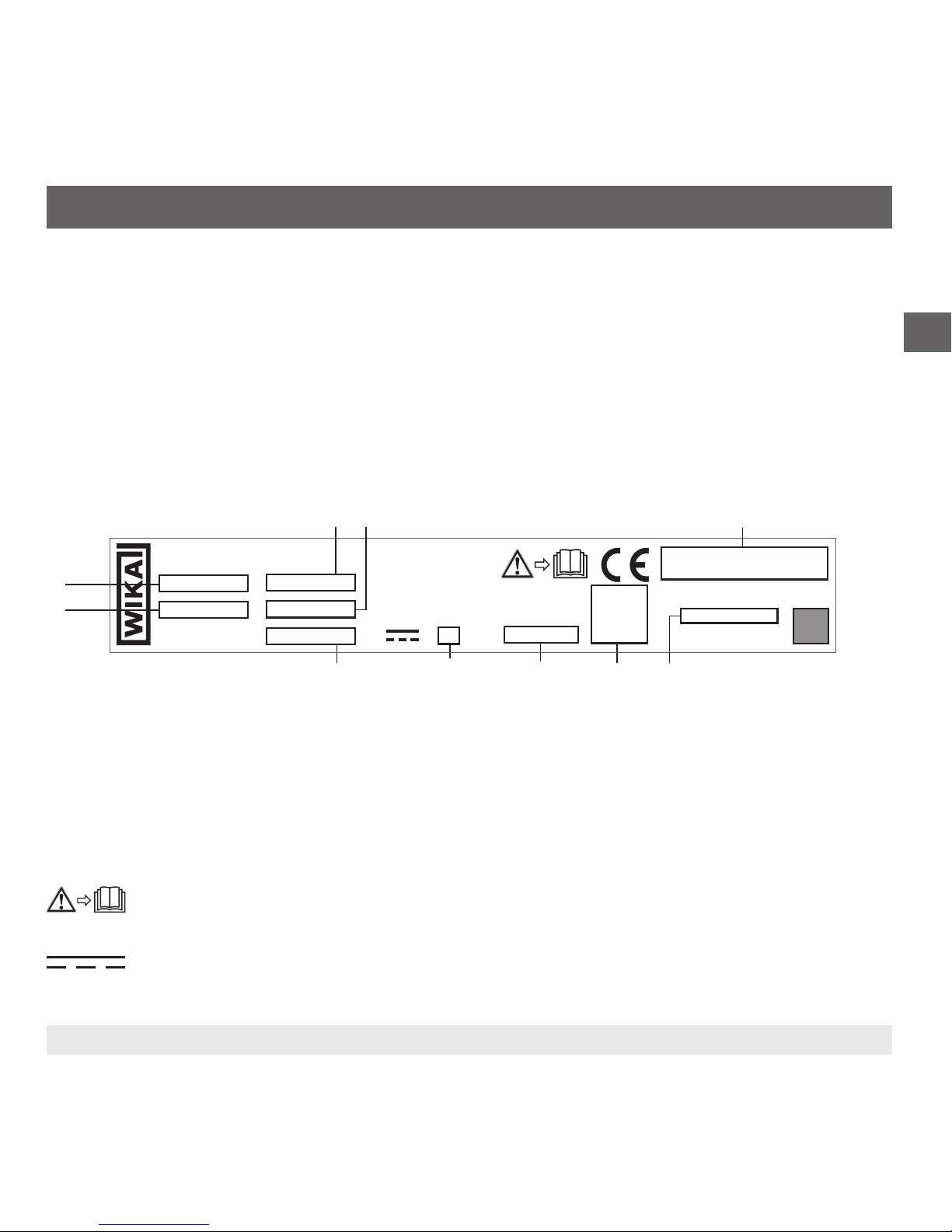
3.4 Labelling, safety marks
Product label
S# Serial no.
Coded manufacture date
P# Product no.
Pin assignment
Measuring range
Non-linearity
Output signal
Total current consumption
Approvals
Power supply
Before mounting and commissioning the instrument, ensure you read the operating instructions!
DC voltage
Model A-10
0 ... 10 bar
www.wika.com
Made in Germany
0 ... 10 bar
/

8 WIKA operating instruction pressure transmitter, model A-10
EN
11218720.15 07/2018 EN/DE/FR/ES
4. Transport, packaging and storage
4. Transport, packaging and storage
4.1 Transport
Check the pressure transmitter for any damage that may have been caused during transportation.
Obvious damage must be reported immediately.
4.2 Packaging and storage
Do not remove packaging until just before mounting.
Keep the packaging as it will provide optimum protection during transport (e.g. change in installation site, sending for
repair).
Permissible conditions at the place of storage:
■
Storage temperature: -40 ... +70 °C
■
Humidity: 45 ... 75 % relative humidity (no condensation)
9WIKA operating instruction pressure transmitter, model A-10
EN
11218720.15 07/2018 EN/DE/FR/ES
5. Commissioning, operation
5. Commissioning, operation
5.1 Mounting the instrument
Only use the pressure transmitter if it is in perfect condition with respect to safety.
Prior to commissioning, the pressure transmitter must be subjected to a visual inspection.
■
Leaking uid is indicative of damage.
Requirements for mounting point
The mounting point must meet the following conditions:
■
Sealing faces are clean and undamaged.
■
Sucient space for a safe electrical installation.
■
For information on tapped holes and welding sockets, see Technical information IN 00.14 at www.wika.com.
■
Permissible ambient and medium temperatures remain within the performance limits. Consider possible restrictions
on the ambient temperature range caused by mating connector used.
→ For performance limits see chapter 9 “Specications”
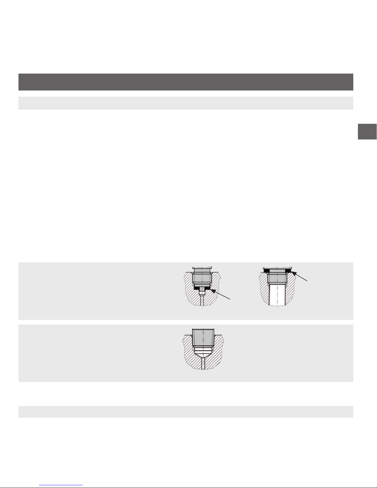
Sealing variants
Parallel threads
Seal the sealing face with flat gasket, lens-type
sealing ring or WIKA profile sealing.
per EN 837
per DIN 3852-E
Tapered threads
Wrap threads with sealing material (e.g. PTFE
tape).
NPT, R and PT

10 WIKA operating instruction pressure transmitter, model A-10
EN
11218720.15 07/2018 EN/DE/FR/ES
Mounting the instrument
The max. torque depends on the mounting point (e.g. material and shape). If you have any questions,
please contact our application consultant.
→ For contact details see chapter 1 “General information” or the back page of the operating instructions.
1. Seal the sealing face (→ see “Sealing variants”).
2
.
At the mounting point, screw the pressure transmitter in hand-tight.
3
.
Tighten with a torque spanner using the spanner ats.
5.2 Connecting the instrument to the electric system
Requirements for voltage supply
→ For power supply see product label
The power supply for the pressure transmitter must be made via an energy-limited electrical circuit in accordance with
section 9.3 of UL/EN/IEC 61010-1, or an LPS per UL/EN/IEC 60950-1, or class 2 in accordance with UL1310/UL1585
(NEC or CEC). The voltage supply must be suitable for operation above 2,000 m should the pressure transmitter be
used at this altitude.
Requirements for electrical connection
■
Cable diameter matches the cable bushing of the mating connector.
■
Cable gland and seals of the mating connector are correctly seated.
■
With cable outlets, no humidity can ingress at the cable end.
Requirement for shielding and grounding
The instrument must be connected to the equipotential bonding of the plant. The connection is made via the process
connection of the instrument.
Connecting the instrument
1. Assemble the mating connector or cable outlet.
→ For pin assignments see product label
2
.
Establish the plug connection.
5. Commissioning, operation
11WIKA operating instruction pressure transmitter, model A-10
EN
11218720.15 07/2018 EN/DE/FR/ES
5. Commissioning, operation
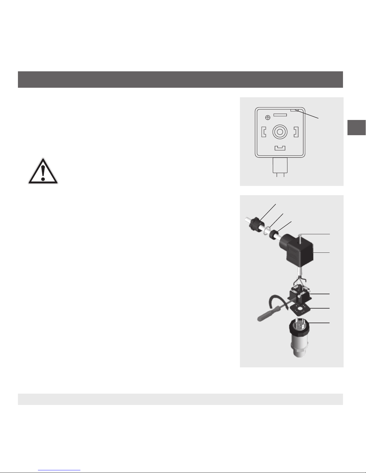
5.3 Fitting a DIN 175301-803 angular connector
1. Loosen the screw (1).
2. Loosen the cable gland (2).
3. Pull the angular connector (5) + (6) away from the instrument.
4. CAUTION!
Improper mounting
The seal of the angle housing will be damaged.
▶
Do not try to push the terminal block (6) out using the
screw hole (1) or the cable gland (2).
Via the mounting hole (D), lever the terminal block (6) out of the angle
housing (5).
5. Slide the cable through the cable gland (2), the ring (3), the sealing (4) and
the angle housing (5).
6. Connect the cable ends to the terminal blocks (6) in accordance with the
connection diagram.
7. Press the angle housing (5) onto the terminal block (6).
8. Make sure that the seals are not damaged and that the cable gland and
seals are correctly seated in order to ensure ingress protection.
9. Tighten the cable gland (2) around the cable.
10. Place the at gasket (7) over the instrument's connection pins.
11. Push the angular connector (5) + (6) onto the instrument.
12. Tighten the screw (1).
(D)
(7)
(5)
(6)
(8)
(1)
(2)
(3)
(4)
12 WIKA operating instruction pressure transmitter, model A-10
EN
11218720.15 07/2018 EN/DE/FR/ES
6. Faults
6. Faults
CAUTION!
Physical injuries and damage to property and the environment
If faults cannot be eliminated by means of the listed measures, the pressure transmitter must be taken
out of operation immediately.
▶
Ensure that pressure or signal is no longer present and protect against accidental commissioning.
▶
Contact the manufacturer.
▶
If a return is needed, please follow the instructions given in chapter 8.2 “Return”.
WARNING!
Physical injuries and damage to property and the environment caused by hazardous media
Upon contact with hazardous media (e.g. oxygen, acetylene, ammable or toxic substances), harmful
media (e.g. corrosive, toxic, carcinogenic, radioactive), and also with refrigeration plants and compressors, there is a danger of physical injuries and damage to property and the environment.
▶
Should a failure occur, aggressive media with extremely high temperature and under high pressure
or vacuum may be present at the instrument.
▶
For these media, in addition to all standard regulations, the appropriate existing codes or regulations
must also be followed.
▶
Wear the requisite protective equipment (see chapter 3.4 “Personal protective equipment”).
For contact details see chapter 1 “General information” or the back page of the operating instructions.
In the event of any faults, rst check whether the pressure transmitter is mounted correctly, mechanically and electrically.
If complaint is unjustied, the handling costs will be charged.

13WIKA operating instruction pressure transmitter, model A-10
EN
11218720.15 07/2018 EN/DE/FR/ES
Faults Causes Measures
No output signal Cable break Check the continuity
Deviating zero point signal Overload safety exceeded Observe the permissible overload safety
Deviating zero point signal Too high/low working temperature Observe the permissible temperatures
Constant output signal upon change in
pressure
Mechanical overload caused by overpressure
Replace instrument; if it fails repeatedly,
contact the manufacturer
Signal span varies EMC interference sources in the environ-
ment; for example, frequency converter
Shield instrument; cable shield; remove
source of interference
Signal span varies/inaccurate Too high/low working temperature Observe the permissible temperatures
Signal span drops/too small Mechanical overload caused by overpres-
sure
Replace instrument; if it fails repeatedly,
contact the manufacturer
If complaint is unjustied, we will charge you the complaint processing fees.
6. Faults
14 WIKA operating instruction pressure transmitter, model A-10
EN
11218720.15 07/2018 EN/DE/FR/ES
7. Maintenance and cleaning
7. Maintenance and cleaning
7.3.1 Maintenance
This pressure transmitter is maintenance-free.
Repairs must only be carried out by the manufacturer.
7.3.2 Cleaning
CAUTION!
Unsuitable cleaning agents
Cleaning with unsuitable cleaning agents may damage the instrument and the product label.
▶
Do not use any aggressive cleaning agents.
▶
Do not use any hard or pointed objects.
▶
Do not use any abrasive cloths or sponges.
Suitable cleaning agents
■
Water
■
Conventional dishwashing detergent
Cleaning the instrument
1. Depressurise and de-energise the pressure transmitter.
2. Wipe the instrument surface using a soft, damp cloth.
15WIKA operating instruction pressure transmitter, model A-10
EN
11218720.15 07/2018 EN/DE/FR/ES
8. Dismounting, return and disposal
8. Dismounting, return and disposal
8.1 Dismounting
WARNING!
Physical injuries and damage to property and the environment caused by hazardous media
Upon contact with hazardous media (e.g. oxygen, acetylene, ammable or toxic substances), harmful
media (e.g. corrosive, toxic, carcinogenic, radioactive), and also with refrigeration plants and compressors, there is a danger of physical injuries and damage to property and the environment.
▶
Should a failure occur, aggressive media with extremely high temperature and under high pressure
or vacuum may be present at the instrument.
▶
Wear the requisite protective equipment.
Dismounting the instrument
1. Depressurise and de-energise the pressure transmitter.
2
.
Disconnect the electrical connection.
3
.
Unscrew the pressure transmitter with a spanner using the spanner ats.
8.2 Return
Strictly observe the following when shipping the instrument:
All instruments delivered to WIKA must be free from any kind of hazardous substances (acids, bases, solutions, etc.)
and must therefore be cleaned before being returned.
WARNING!
Physical injuries and damage to property and the environment through residual media
Residual media in the dismounted instrument can result in a risk to persons, the environment and
equipment.
▶
With hazardous substances, include the material safety data sheet for the corresponding medium.
▶
Clean the instrument, see chapter 7.2 “Cleaning”.
16 WIKA operating instruction pressure transmitter, model A-10
EN
11218720.15 07/2018 EN/DE/FR/ES
8. Dismounting, return
When returning the instrument, use the original packaging or a suitable transport packaging.
Information on returns can be found under the heading “Service” on our local website.
8.3 Disposal
Incorrect disposal can put the environment at risk.
Dispose of instrument components and packaging materials in an environmentally compatible way and in accordance
with the country-specic waste disposal regulations.
Do not dispose of with household waste. Ensure a proper disposal in accordance with national regulations.

17WIKA operating instruction pressure transmitter, model A-10
EN
11218720.15 07/2018 EN/DE/FR/ES
9. Specications
Measuring ranges and overload safetys (gauge pressure)
bar Measuring range 0 ... 0.05 0 ... 0.1 0 ... 0.16 0 ... 0.25 0 ... 0.4 0 ... 0.6
Overload safety 0.2 0.2 1 1 1 3
Measuring range 0 ... 1 0 ... 1.6 0 ... 2.5 0 ... 4 0 ... 6 0 ... 10
Overload safety 3 3.2 5 8 12 20
Measuring range 0 ... 16 0 ... 25 0 ... 40 0 ... 60 0 ... 100 0 ... 160
Overload safety 32 50 80 120 200 320
Measuring range 0 ... 250 0 ... 400 0 ... 600 0 ... 1,000
Overload safety 500 800 1,200 1,500
inWC Measuring range 0 ... 20 0 ... 40 0 ... 60 0 ... 80 0 ... 100 0 ... 120
Overload safety 84 84 400 400 400 400
Measuring range 0 ... 150 0 ... 200 0 ... 250 0 ... 400
Overload safety 400 400 1,200 1,200
psi Measuring range 0 ... 1 0 ... 5 0 ... 15 0 ... 25 0 ... 30 0 ... 50
Overload safety 3 14.5 45 60 60 100
Measuring range 0 ... 100 0 ... 160 0 ... 200 0 ... 300 0 ... 500 0 ... 1,000
Overload safety 200 290 400 600 1,000 1,740
Measuring range 0 ... 1,500 0 ... 2,000 0 ... 3,000 0 ... 5,000 0 ... 10,000
Overload safety 2,900 4,000 6,000 10,000 17,400
9.Specications

18 WIKA operating instruction pressure transmitter, model A-10
EN
11218720.15 07/2018 EN/DE/FR/ES
Measuring ranges and overload safetys (absolute pressure)
bar Measuring range 0 ... 0.1 0 ... 0.16 0 ... 0.25 0 ... 0.4 0 ... 0.6 0 ... 1 0 ... 1.6
Overload safety 1 1 1 1 3 3 3.2
Measuring range 0 ... 2.5 0 ... 4 0 ... 6 0 ... 10 0 ... 16 0 ... 25
Overload safety 5 8 12 20 32 50
inWC Measuring range 0 ... 40 0 ... 60 0 ... 80 0 ... 100 0 ... 120 0 ... 150 0 ... 200
Overload safety 400 400 400 400 400 400 400
Measuring range 0 ... 250 0 ... 400
Overload safety 1,200 1,200
psi Measuring range 0 ... 5 0 ... 15 0 ... 25 0 ... 30 0 ... 50 0 ... 100 0 ... 150
Overload safety 14.5 45 60 60 100 200 290
Measuring range 0 ... 200 0 ... 300
Overload safety 400 600
Measuring ranges and overload safetys (vacuum and +/- measuring ranges)
bar Measuring range -0.025 ... +0.025 -0.05 ... 0 -0.05 ... +0.05 -0.05 ... +0.15 -0.05 ... +0.2
Overload safety ±0.2 ±0.2 ±0.2 1 1
Measuring range -0.05 ... +0.25 -0.1 ... 0 -0.1 ... +0.1 -0.15 ... +0.15 -0.16 ... 0
Overload safety 1 ±0.2 1 1 1
Measuring range -0.2 ... +0.2 -0.25 ... 0 -0.25 ... +0.25 -0.3 ... +0.3 -0.4 ... 0
Overload safety 1 1 1 3 1
Measuring range -0.5 ... +0.5 -0.6 ... 0 -1 ... 0 -1 ... +0.6 -1 ... +1.5
Overload safety 3 3 3 3.2 5
Measuring range -1 ... +3 -1 ... +5 -1 ... +9 -1 ... +15 -1 ... +24
Overload safety 8 12 20 32 50
9.Specications

19WIKA operating instruction pressure transmitter, model A-10
EN
11218720.15 07/2018 EN/DE/FR/ES
Measuring ranges and overload safetys (vacuum and +/- measuring ranges)
inWC Measuring range -10 ... +10 -20 ... 0 -20 ... +20 -40 ... 0 -40 ... +40
Overload safety ±80 ±80 ±80 ±80 ±80
Measuring range -50 ... +50 -60 ... 0 -75 ... +75 -80 ... 0 -100 ... 0
Overload safety 400 400 400 400 400
Measuring range -100 ... +100 -120 ... 0 -125 ... +125 -150 ... 0 -200 ... +200
Overload safety 400 400 1,200 400 1,200
Measuring range -250 ... 0
Overload safety 1,200
psi Measuring range -1 ... 0 -30 inHg ... 0 -30 inHg ... +15 -30 inHg ... +30 -30 inHg ... +60
Overload safety 3 45 60 60 150
Measuring range -30 inHg ... +100 -30 inHg ... +160 -30 inHg ... +200 -30 inHg ... +300
Overload safety 250 350 450 600
Specications
Vacuum tightness Yes (for restrictions see overload safety)
Output signal see product label
Load Current (2-wire) ≤ (power supply - 8 V) / 0.02 A
Voltage (3-wire) > maximum output signal / 1 mA
Ratiometric (3-wire) > 10k
Power supply see product label
Total current consumption Current (2-wire) Signal current, max. 25 mA
Voltage (3-wire) 8 mA
Ratiometric (3-wire) 8 mA
9.Specications

20 WIKA operating instruction pressure transmitter, model A-10
EN
11218720.15 07/2018 EN/DE/FR/ES
Specications
Non-repeatability Measuring range ≤ 0.1 bar: ≤ ±0.2 % of span
Measuring range > 0.1 bar: ≤ ±0.1 % of span
Signal noise ≤ ±0.3 % of span
Temperature error at 0 ... 80 °C Typical: ≤ ±1 % of span
Maximum: ≤ ±2.5 % of span
Reference conditions Ambient temperature 15 ... 25 °C
Atmospheric pressure 860 ... 1,060 mbar
Humidity 45 ... 75 % r. h.
Power supply DC 24 V
Mounting position as required
Settling time Measuring range ≥ 0.4 bar: < 4 ms
Measuring range ≥ 0.05 bar: < 1 min
Switch-on time Measuring range ≥ 0.4 bar: < 15 ms
Measuring range ≥ 0.05 bar: < 1 min
Ingress protection The stated ingress protection only applies when plugged in using mating connectors that have
the appropriate ingress protection.
Angular connector DIN 175301-803 A IP65
Angular connector DIN 175301-803 C IP65
Circular connector M12 x 1 IP67
Cable outlet IP67
Shock resistance 500 g (IEC 60068-2-27, mechanical)
100 g at -40 °C
Service life Measuring range > 0.1 bar: 100 million load cycles
Measuring range ≤ 0.1 bar: 10 million load cycles
Short-circuit resistance S+ vs. 0V
Reverse polarity protection U
B
vs. 0V
no reverse polarity protection with ratiometric output signal
9.Specications

21WIKA operating instruction pressure transmitter, model A-10
EN
11218720.15 07/2018 EN/DE/FR/ES
Specications
Insulation voltage DC 500 V
Wetted parts Measuring range < 10 bar Stainless steel 316L
Measuring range ≥ 10 bar Stainless steel 316L and PH grade steel
Measuring range ≤ 0 ... 25 bar abs. Stainless steel 316L
Non-wetted parts Stainless steel 316L, HNBR, PA, cable from PUR
Pressure transmission medium Measuring range < 0 ... 10 bar gauge Synthetic oil
Measuring range ≤ 0 ... 25 bar absolute Synthetic oil
Measuring range ≥ 0 ... 10 bar gauge Dry measuring cell
For further specications see WIKA data sheet PE 81.60 and the order documentation.
9.Specications
22 WIKA operating instruction pressure transmitter, model A-10
EN
11218720.15 07/2018 EN/DE/FR/ES
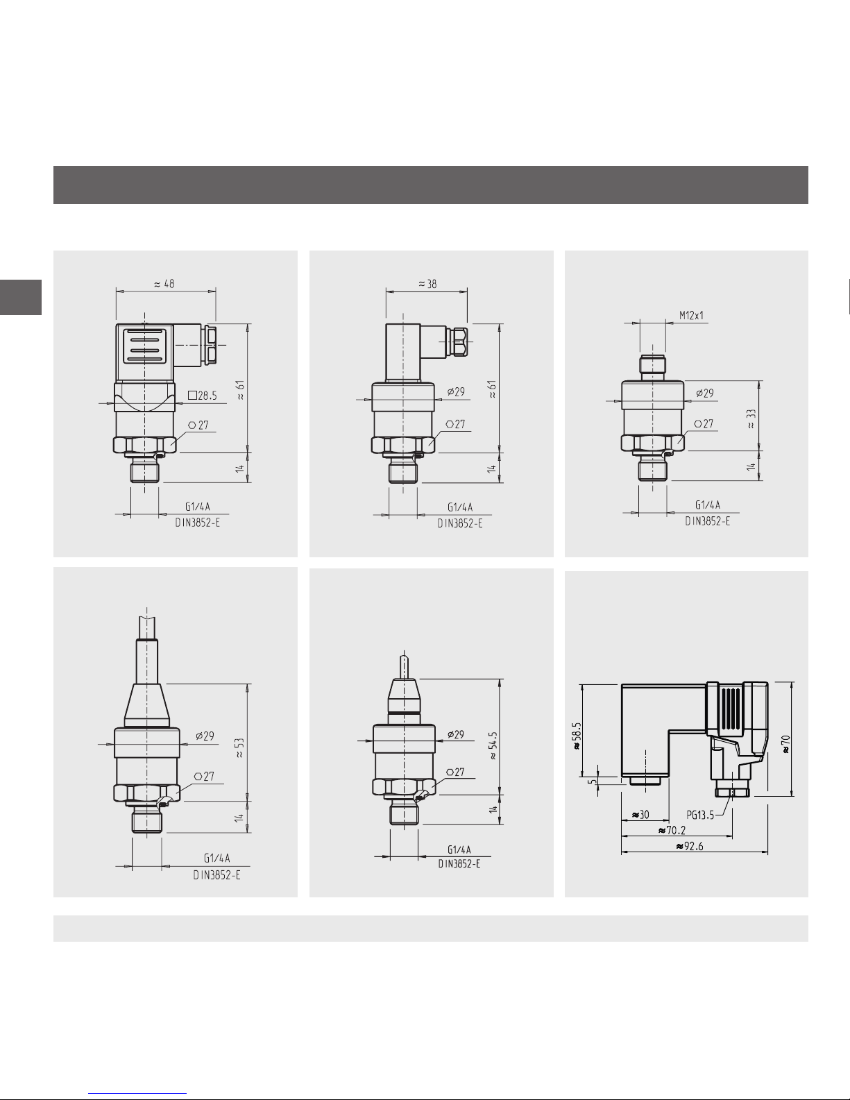
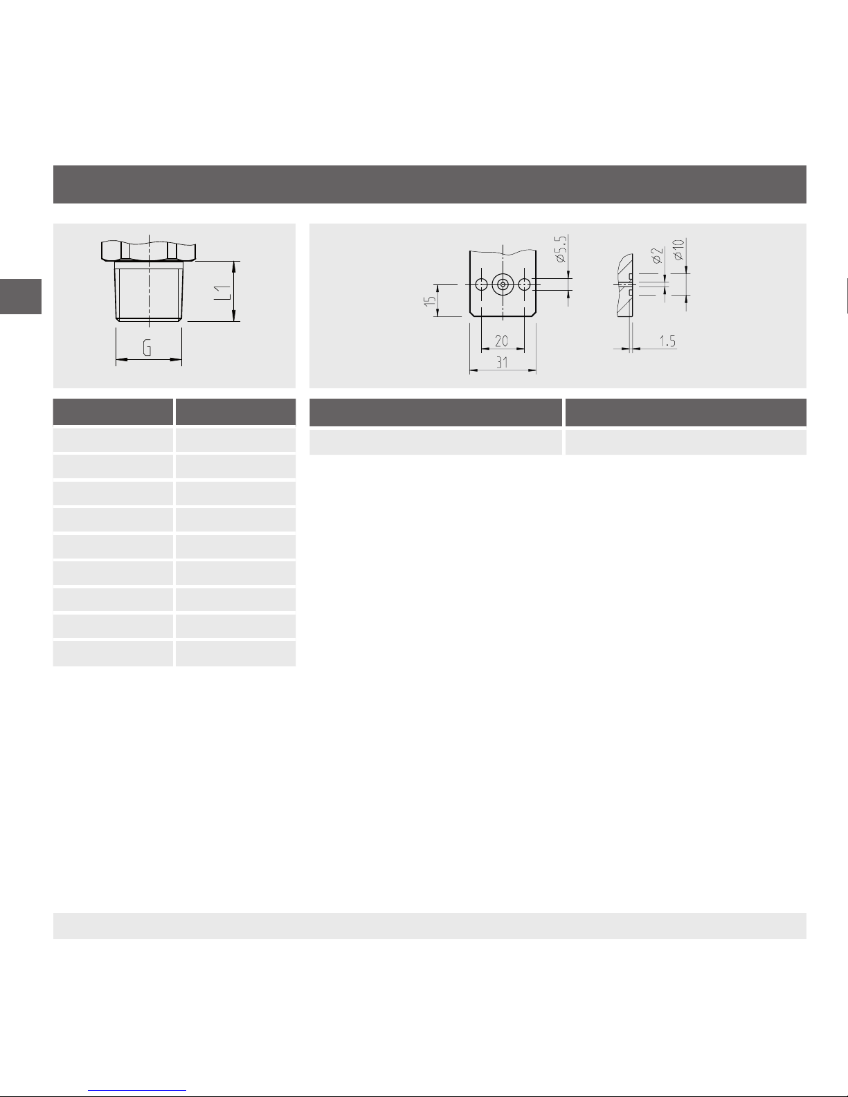
Dimensions in mm
Angular connector form A Angular connector form C Circular connector M12 x 1
Standard cable outlet, unshielded
Cable outlet OEM version, unshielded
Angular connector form A, ange
connection
Weight: approx. 80 g Weight: approx. 80 g Weight: approx. 80 g
Weight: approx. 80 g Weight: approx. 80 g
9.Specications
Weight: approx. 350 g
23WIKA operating instruction pressure transmitter, model A-10
EN
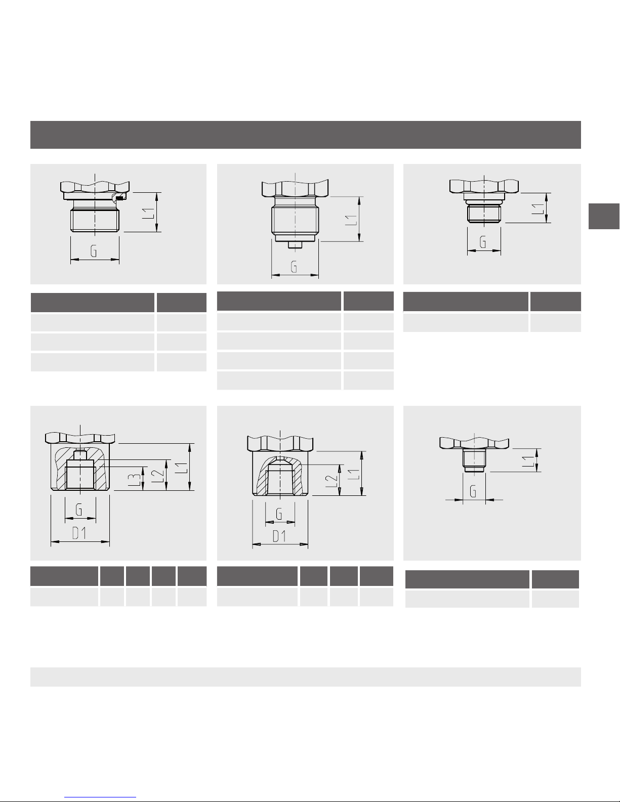
11218720.15 07/2018 EN/DE/FR/ES
G L1
G ¼ A DIN 3852-E 14
G ½ A DIN 3852-E 17
M14 x 1.5 14
G L1
G ¼ B EN 837 13
G ⅜ B EN 837 16
G ½ B EN 837 20
M20 x 1.5 20
G L1
7/16-20 UNF BOSS 12.85
G L1 L2 L3 D1
G ¼ EN 837 20 13 10 Ø 25
Female thread
G L1 L2 D1
¼ NPT 20 14 Ø 25
G L1
G ⅛ B EN 837 10
Female thread
9.Specications
24 WIKA operating instruction pressure transmitter, model A-10
EN
11218720.15 07/2018 EN/DE/FR/ES
G L1
⅛ NPT 10
¼ NPT 13
½ NPT 19
R ¼ 13
R ⅜ 15
R ½ 19
PT ¼ 13
PT ⅜ 15
PT ½ 19
G ¼ female, with ange connection For dimensions see drawing
For special models A-10000 or special version A-10, other technical specications apply. Please note the
specications stated on the order conrmation and the delivery note.
For further specications see WIKA data sheet PE 81.60 and the order documentation.
9.Specications

25WIKA Betriebsanleitung Druckmessumformer, Typ A-10
DE
11218720.15 07/2018 EN/DE/FR/ES
Inhalt
Konformitätserklärungen finden Sie online unter www.wika.de
Inhalt
1. Allgemeines 26
2. Aufbau und Funktion 27
3. Sicherheit 28
4. Transport, Verpackung und Lagerung 30
5. Inbetriebnahme, Betrieb 31
6. Störungen 34
7. Wartung und Reinigung 36
8. Demontage, Rücksendung und Entsorgung 37
9. Technische Daten 39

26 WIKA Betriebsanleitung Druckmessumformer, Typ A-10
DE
11218720.15 07/2018 EN/DE/FR/ES
1. Allgemeines
1. Allgemeines
■
Das in der Betriebsanleitung beschriebene Gerät wird nach dem aktuellen Stand der Technik konstruiert und
gefertigt. Alle Komponenten unterliegen während der Fertigung strengen Qualitäts- und Umweltkriterien. Unsere
Managementsysteme sind nach ISO 9001 und ISO 14001 zertiziert.
■
Diese Betriebsanleitung gibt wichtige Hinweise zum Umgang mit dem Gerät. Voraussetzung für sicheres Arbeiten ist
die Einhaltung aller angegebenen Sicherheitshinweise und Handlungsanweisungen.
■
Die für den Einsatzbereich des Gerätes geltenden örtlichen Unfallverhütungsvorschriften und allgemeinen Sicherheitsbestimmungen einhalten.
■
Die Betriebsanleitung ist Produktbestandteil und muss in unmittelbarer Nähe des Gerätes für das Fachpersonal
jederzeit zugänglich aufbewahrt werden. Betriebsanleitung an nachfolgende Benutzer oder Besitzer des Gerätes
weitergeben.
■
Das Fachpersonal muss die Betriebsanleitung vor Beginn aller Arbeiten sorgfältig durchgelesen und verstanden
haben.
■
Es gelten die allgemeinen Geschäftsbedingungen in den Verkaufsunterlagen.
■
Technische Änderungen vorbehalten.
■
Weitere Informationen:
- Internet-Adresse: www.wika.de / www.wika.com
- Zugehöriges Datenblatt: PE 81.60
- Anwendungsberater:
Tel.: +49 9372 132-0
Fax: +49 9372 132-406
info@wika.de
27WIKA Betriebsanleitung Druckmessumformer, Typ A-10
DE
11218720.15 07/2018 EN/DE/FR/ES
2. Aufbau und Funktion
2. Aufbau und Funktion
2.1 Überblick
Elektrischer Anschluss (je nach Ausführung)
Gehäuse; Typenschild
Prozessanschluss, Schlüsselfläche
Prozessanschluss, Gewinde
2.2 Lieferumfang
■
Druckmessumformer
■
Betriebsanleitung
Lieferumfang mit dem Lieferschein abgleichen.
28 WIKA Betriebsanleitung Druckmessumformer, Typ A-10
DE
11218720.15 07/2018 EN/DE/FR/ES
3. Sicherheit
3. Sicherheit
3.1 Symbolerklärung
WARNUNG!
... weist auf eine möglicherweise gefährliche Situation hin, die zum Tod oder zu schweren Verletzungen
führen kann, wenn sie nicht gemieden wird.
VORSICHT!
... weist auf eine möglicherweise gefährliche Situation hin, die zu geringfügigen oder leichten
Verletzungen bzw. Sach- und Umweltschäden führen kann, wenn sie nicht gemieden wird.
Information
... hebt nützliche Tipps und Empfehlungen sowie Informationen für einen ezienten und störungsfreien
Betrieb hervor.
3.2 Bestimmungsgemäße Verwendung
Der Druckmessumformer dient der Messung von Druck. Der gemessene Druck wird als elektrisches Signal
ausgegeben.
Dies ist ein Gerät der Klasse B für Störaussendung und ist für den Betrieb in industrieller Umgebung vorgesehen. In
anderen Umgebungen, z. B. im Wohn- oder Gewerbebereich, kann sie unter Umständen andere Einrichtungen störend
beeinussen. In diesem Fall kann vom Betreiber verlangt werden, angemessene Maßnahmen durchzuführen.
Den Druckmessumformer nur in Anwendungen verwenden, die innerhalb seiner technischen Leistungsgrenzen liegen
(z. B. max. Umgebungstemperatur, Materialverträglichkeit, ...).
→ Leistungsgrenzen siehe Kapitel 9 „Technische Daten“.
Das Gerät ist ausschließlich für den hier beschriebenen bestimmungsgemäßen Verwendungszweck konzipiert und
konstruiert und darf nur dementsprechend verwendet werden.
Ansprüche jeglicher Art aufgrund von nicht bestimmungsgemäßer Verwendung sind ausgeschlossen.
 Loading...