


Whirlpool WTW5600XW, WTW4950XW, WTW5700XW, WTW5550XW, WTW5500XW User Manual
...L-84
TECHNICAL EDUCATION
Vertical Modular
Washer
MVWC400XW WTW4950XW
MVWX500XW WTW5500XW
MVWX550XW WTW5550XW
MVWX600XW WTW5600XW
MVWX700XW WTW5700XW
JOB AID W10329932

FORWARD
This Whirlpool Job Aid, "Vertical Modular Washer" (Part No. W10329932), provides
the In-Home Service Professional with information on the installation, operation, and service of the "Vertical Modular Washer". For specific information on the model
being serviced, refer to the “Use and Care Guide,” or “Tech Sheet” provided with the washer.
The Wiring Diagram used in this Job Aid is typical and should be used for training purposes only.
Always use the Wiring Diagram supplied with the product when servicing the washer.
GOALS AND OBJECTIVES
The goal of this Job Aid is to provide information that will enable the In-Home Service
Professional to properly diagnose malfunctions and repair the "Vertical Modular Washer"
The objectives of this Job Aid are to:
•Understand and follow proper safety precautions.
•Successfully troubleshoot and diagnose malfunctions.
•Successfully perform necessary repairs.
•Successfully return the washer to its proper operational status.
WHIRLPOOL CORPORATION assumes no responsibility for any repairs made on our products by anyone other than authorized In-Home Service Professionals.
Copyright © 2010, Whirlpool Corporation, Benton Harbor, MI 49022
- ii -
TABLE OF CONTENTS
Page
GENERAL . . . . . . . . . . . . . . . . . . 1-1
GENERAL . . . . . . . . . . . . . . . . . . . . . . . . . . . . 1-1
Washer Safety. . . . . . . . . . . . . . . . . . . . . . . . . . . . 1-1
Model & Serial Number Designations. . . . . . . . . . . . . . . . . . . . . . . . . . . . . . . . . 1-2
Model & Serial Number Label And Tech Sheet Locations. . . . . . . . . . . . . . . . . . . . . . . . 1-4
Specifications . . . . . . . . . . . . . . . . . . . . . . . . . . . . . . . . . . . . . . . . . 1-5
Specifications (Maytag Models). . . . . . . . . . . . . . . . . . 1-6
INSTALLATION INFORMATION . |
. . . . . . . . . . . . . |
. . . . . . |
. |
. |
|
. |
|
. |
|
|
|
|
|
2-1 |
|||||
Washer Safety. . . . . |
. . . . . . . . . |
. . . . . . . . . . . |
. . . . . . |
. |
. |
|
. |
|
|
|
|
|
|
2-1 |
|||||
Installation Requirements. . . . . |
. . . . . . . . . . . . |
. . . . . . . . |
. . |
. . |
. . |
. . . . |
. |
. |
. . . . . 2-2 |
||||||||||
Electrical Requirements. . . . . . . . . . . . . . |
. |
. |
. |
. |
|
|
|
2-4 |
|||||||||||
Installation Instructions . . . . . . . . . . . . . . |
. |
. |
. |
. |
|
|
|
2-4 |
|||||||||||
PRODUCT OPERATION. . . . . . . . |
. . . . . . . . . . . . |
. . . . . . . . . |
. |
. . . . . |
. |
. |
|
. . . . |
|
3-1 |
|||||||||
Theory Of Operation. . . . . . . . . |
. . . . . . . . . . . . |
. . . . . |
. . . . . . |
. |
. |
|
. . . . |
|
3-1 |
||||||||||
Introduction. . . . . . . |
. . . . . . . . . |
. . . . . . . . . . |
. . . . . . |
. |
. |
|
|
3-1 |
|||||||||||
Drive System. . . . . . |
. . . . . . . . . |
. . . . . . . . . . . . |
. . . . . |
. |
. |
. |
|
. |
3-1 |
||||||||||
Actuator. . . . . . . . . |
. . . . . . . . . . . . . . . |
. |
. |
|
|
|
|
3-3 |
|||||||||||
Lid Lock Mechanism . . . . . . . . . . . . . . . |
. |
. |
. |
|
|
|
|
3-4 |
|||||||||||
Control Panel And Features. . . . . . . . . . . . |
. . . . . . |
|
|
|
|
3-5 |
|||||||||||||
Cycle Guide. . . . . . . . . . . . . . . . . . |
|
|
|
|
3-8 |
||||||||||||||
Using The Washer. . . . . . . . . . . . . . . . |
. |
. |
|
|
|
3-9 |
|||||||||||||
Using Laundry Product Dispensers. . . . . . . . . |
. . . . . . |
. |
. |
|
. |
|
3-10 |
||||||||||||
Troubleshooting. . . . . . . . . . . . . . . . . |
. |
|
|
|
|
3-14 |
|||||||||||||
COMPONENT ACCESS . . . . . . . |
. . . . . . . . . . . |
. . . . . |
. |
. |
|
|
|
4-1 |
|||||||||||
Component Locations. . . . . . . . . |
. . . . . . . . . . |
. . . . . |
. |
. |
. |
4-1 - 4-2 |
|||||||||||||
Removing The Control Panel. . . . . . . . . . . . |
. . . . . |
. |
|
|
|
4-3 |
|||||||||||||
Removing The Control. . . . . . . . . . . . . . |
. |
. |
. |
. |
|
|
|
4-4 |
|||||||||||
User Interface Removal And Installation Procedure. . . . . |
. . |
. . |
. . |
. . . |
. |
. |
|
. . . . |
|
4-5 |
|||||||||
Removing The Top. . |
. . . . . . . . . |
. . . . . . . . . . . . |
.. . . . |
. . . . . |
. |
. |
. . . . . 4-6 |
||||||||||||
Removing The Water Inlet Valve. . . . . . . . . . . |
. . . . |
. . . . . . |
. |
. |
|
. . . . |
|
4-7 |
|||||||||||
Removing The Detergent Dispenser Assembly. |
. . . . . . . |
. . . . . . |
. |
. |
|
. . . . |
|
4-8 |
|||||||||||
Removing The Lid Switch/Lock Assembly. . . . . . |
. . . . . |
. . . . . |
. |
. |
. . . . . 4-9 |
||||||||||||||
Removing The Lid Strike On Glass Lid Models. . |
. . . . . . . |
. . |
. . |
. . |
. . |
. |
. |
. |
|
. . . |
|
4-10 |
|||||||
Removing The Shifter. . . . . . . . . |
. . . . . . . . . . . . . |
. . . . . |
. |
. |
. |
|
. |
|
. |
|
. |
4-11 |
|||||||
Removing The Drain Pump. . . . . |
. . . . . . . . . . . . |
. . . |
. . . . . . |
. |
. |
|
. |
|
. |
|
. |
|
. 4-12 |
||||||
Removing The Drive Belt And Motor. . . . . . . . . . |
. . . . . . |
. . . . . |
. |
. |
. |
|
. . . |
|
4-13 |
||||||||||
Removing The Splutch . . . . . . . . |
. . . . . . . . . . . . |
. . . . . |
. . . . . |
. |
. |
. |
|
. . . |
|
4-14 |
|||||||||
Removing The Gearcase. . . . . . . . . . . . . |
. |
. |
. |
. . |
|
|
|
|
4-15 |
||||||||||
Removing The Tub Ring. . . . . . . . |
. . . . . . . . . . . . . |
. . . . . . |
. |
. |
|
. |
|
. . . |
4-17 |
||||||||||
Removing The Impeller And Basket. . . . . . . . . . .. |
. . . |
. . . . . |
. |
. |
. |
|
. . . |
|
4-18 |
||||||||||
Basket Drive Block Removal And Installation Procedure . |
. . . . . |
. |
. |
. |
|
. . . |
|
4-19 |
|||||||||||
Removing the Tub. . . . . . . . . . . . . . . . |
. |
. |
|
|
|
|
4-21 |
||||||||||||
- iii -
TABLE OF CONTENTS (continued)
TESTING . . . . . . . . . . . . . . . |
. |
. |
. |
5-1 |
||||||||||
Activating The Service Diagnostic Modes . |
. . |
. . |
. . |
. . |
. . |
. . |
. . |
. . . . . . . . . . . |
5-2 |
|||||
Diagnostic Guide. . . . . . . . . . . |
. . . . . . . . . |
. . |
. . |
. . |
. . . . . . . . . . . . . . . |
5-3 |
||||||||
Fault Code Display Mode. . . . . |
. . . . . . . . . |
. . |
. . |
. . |
. . |
. |
. . . . . . . . . . . . . |
5-3 |
||||||
Automatic Test Mode. . . . . . . . . |
. . . . . . . . . |
. . |
. . |
. |
. . |
. . |
. . |
. . . . . . . . . . . . |
5-4 |
|||||
Manual Test Mode. . . . . . . . . . . |
. . . . . . . . . |
. . |
. |
. . . . . . . . . . . . . . . . |
5-4 |
|||||||||
Calibration Mode. . . . . . . . . . . |
. . . . . |
. |
. |
. |
. |
. |
. |
. |
. . |
. |
. |
. |
5-4 |
|
Sales Demo Mode . . . . . . . . . . |
. . . . . |
. |
. |
. |
. |
. |
. |
. |
. . |
. |
. |
. . |
5-4 |
|
UI Test Mode . . |
. . . . . . . . . . . . . |
. . . . . . . . . |
. . |
. . |
. |
. . . . . . . . . . . . . . . |
5-5 |
|||||||
Software Version Display Mode. . . . . |
. |
. |
. |
. |
. |
. |
. |
. . |
. . |
. |
. |
5-5 |
||
Customer Viewable Fault .Codes . . . . . . . . . |
. |
. . . . . . . . . . . . . . . . |
5-5 |
|||||||||||
Automatic Test Mode . . . . . . . . . |
. . . . . |
. |
. |
. |
. |
. |
. |
. |
. . |
. |
. |
. . . |
5-8 |
|
Manual Test Mode . . . . . . . . . . . . |
. . . . . . . . . |
. |
. . |
. |
. . |
. |
. . . . . . . . . . . . . |
5-9 |
||||||
DIAGNOSTICS . . |
. . . . . . . . . . . |
. |
. |
. |
. |
. |
6-1 |
|||||||
Diagnostic Guide. . . . . . . . . . . . . . |
. . . . . . . . . |
. |
. . |
. |
. .. |
. . . . . . . . . . . . . |
6-1 |
|||||||
Troubleshooting Tests . . . . . . . . . |
. . . . . . . . . |
|
. . . . . . . . . . . . . . . . . |
6-4 |
||||||||||
WIRING DIAGRAMS . . . . . . . . . . |
. |
. |
. |
. |
. |
. |
. |
. |
7-1 |
|||||
Washer. . . . . . . . . . . . . . . |
. |
. |
. |
7-1 |
||||||||||
- iv -

GENERAL
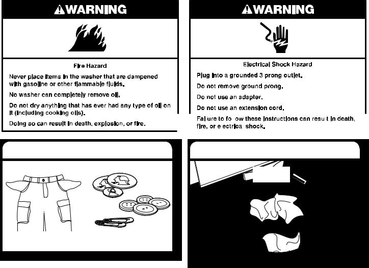
WASHER SAFETY
Your safety and the safety of others are very important.
We have provided many important safety messages in this manual and on your appliance.
Always read and obey all safety messages. This is the safety alert symbol.
This symbol alerts you to potential hazards that can kill or hurt you and others.
All safety messages will follow the safety alert symbol and either the word “DANGER” or “WARNING.” These words mean:
 DANGER
 WARNING
You can be killed or seriously injured if you don’t immediately follow instructions.
You can be killed or seriously injured if you don’t follow instructions.
All safety messages will tell you what the potential hazard is, tell you how to reduce the chance of injury, and tell you what can happen if the instructions are not followed.
IMPORTANT: Electrostatic Discharge (ESD) Sensitive Electronics
ESD problems are present everywhere. Most people begin to feel an ESD discharge at approximately 3000V. It takes as little as 10V to destroy, damage, or weaken the main control assembly. The new main control assembly may appear to work well after repair is finished, but a malfunction may occur at a later date due to ESD stress.
Use an anti-static wrist strap. Connect wrist strap to green ground connection point or unpainted metal in the appliance
-OR-
Touch your finger repeatedly to a green ground connection point or unpainted metal in the appliance.
Before removing the part from its package, touch the anti-static bag to a green ground connection point or unpainted metal in the appliance.
Avoid touching electronic parts or terminal contacts; handle electronic control assembly by edges only.
When repackaging main control assembly in anti-static bag, observe above instructions.
1-1

MODEL & SERIAL NUMBER DESIGNATIONS
MODEL NUMBER |
|
W T W 4 2 00 X Q 0 |
|
BRAND
A=Admirl C=Crosley E=Estate I=Inglis M=Maytag
N=Amana R=Roper W=Whirlpool
ACCESS
E=Electric F=Front Load G=Gas H=Horizontial
T=Top Load V=Vertical W=Workspace
PRODUCT
B=Combo C=Compact D=Dryer P=Pedestal T=Thin
Twin/Stack W = Washer
SERIES
1=Innovation 2=Commercial 3=Compact 4=VMW Good & Stack 5=LEAP & VMW Better 6=Oasis 7=24" Front Load & VMW Best 8=Mid Line Front Load 9=Duet Front Load
PRICE POINT LEVELS (1-9)
TRADE PARTNER ID (00 = BRANDED)
YEAR OF INTRODUCTION
X = 2010
COLOR CODE
A=Aspen B=Black C=Tuscan Chestnut E=Ocean Sapphire F=Classic
Red K=Blue L=Silver/Pewter Q=Mono White T=Bisque U=Ult Silver
W=White w/Gray Z=White w/Sapphire
ENGINEERING CHANGE (0, 1, 2, ETC.)
SERIAL NUMBER |
|
C |
|
0 |
|
41 |
|
01002 |
|
|
|
|
|
|
|||||
DIVISION RESPONSIBILITY |
|
|
|
|
|
|
|
|
|
C = CLYDE, OH |
|
|
|
|
|
|
|
|
|
YEAR OF PRODUCTION |
|
|
|
|
|
|
|
|
|
2010 = 0 2011 = 1 |
|
|
|
|
|
|
|
|
|
WEEK OF PRODUCTION |
|
|
|
|
|
|
|
|
|
41 = 41ST WEEK |
|
|
|
|
|
|
|
|
|
PRODUCT SEQUENCE NUMBER |
|
|
|
|
|
|
|
|
|
1-2

MODEL & SERIAL NUMBER DESIGNATIONS (MAYTAG)
MODEL NUMBER |
|
M E W X 7 00 X Q 0 |
|
BRAND
A=Admirl C=Crosley E=Estate I=Inglis M=Maytag
N=Amana R=Roper W=Whirlpool
ACCESS
E=Electric F=Front Load G=Gas H=Horizontial
T=Top Load V=Vertical W=Workspace
PRODUCT
B=Combo C=Compact D=Dryer P=Pedestal T=Thin
Twin/Stack W = Washer
SERIES
A=All / Accessory B=Bravos C=Centennial E=Epic
S=Stack X=VMW Better Z=Epic Z
PRICE POINT LEVELS (1-9)
TRADE PARTNER ID (00 = BRANDED)
YEAR OF INTRODUCTION X = 2010
COLOR CODE
A=Aspen B=Black C=Tuscan Chestnut E=Ocean Sapphire F=Classic
Red K=Blue L=Silver/Pewter Q=Mono White T=Bisque U=Ult Silver
W=White w/Gray Z=White w/Sapphire
ENGINEERING CHANGE (0, 1, 2, ETC.)
SERIAL NUMBER |
|
C |
|
0 |
|
41 |
|
01002 |
|
|
|
|
|
|
|||||
DIVISION RESPONSIBILITY |
|
|
|
|
|
|
|
|
|
C = CLYDE, OH |
|
|
|
|
|
|
|
|
|
YEAR OF PRODUCTION |
|
|
|
|
|
|
|
|
|
2010 = 0 2011 = 1 |
|
|
|
|
|
|
|
|
|
WEEK OF PRODUCTION |
|
|
|
|
|
|
|
|
|
41 = 41ST WEEK |
|
|
|
|
|
|
|
|
|
PRODUCT SEQUENCE NUMBER |
|
|
|
|
|
|
|
|
|
1-3
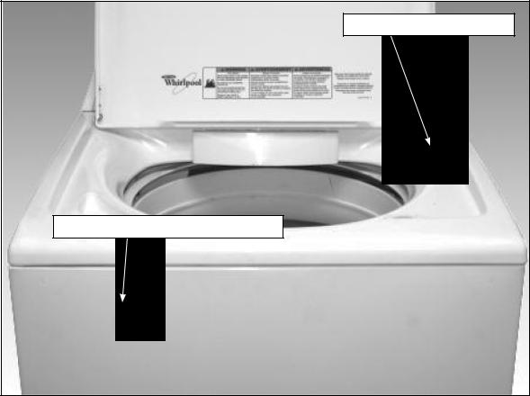
MODEL & SERIAL NUMBER LABEL
AND TECH SHEET LOCATIONS
The Model & Serial Number Label and Tech Sheet locations are shown below.
Model & Serial Number Label |
Tech Sheet (Behind Front Panel) |
1-4

SPECIFICATIONS
|
Model Number |
WTW49550XW |
|
WTW5500XW |
|
WTW5550XW |
|
Model Description |
Top-Load Washer |
|
Top-Load Washer |
|
Top-Load Washer |
|
Color |
White |
|
White |
|
White |
|
Capacity (Cu. Ft. DOE) |
3.7 |
|
3.7 |
|
3.7 |
|
IEC Capacity |
4.3 |
|
|
|
|
|
4.3 |
|
4.3 |
|||
|
Energy Star / Tier Level (2011 |
2.4 MEF, 4.0 WF |
|
|
|
|
|
2.4 MEF, 4.0 WF |
|
2.4 MEF, 4.0 WF |
|||
|
Basket Material |
Stainless Steel |
|
|
|
|
|
Stainless Steel |
|
Stainless Steel |
|||
|
Bleach Disp. |
Dump Bleach |
|
|
|
|
|
Dump Bleach |
|
Dump Bleach |
|||
|
Fab. Sof. Disp. |
Downeyball |
|
Timed Flush-Drawer |
|
Timed Flush-Drawer |
|
Detergent Disp. |
No |
|
Drawer |
|
Drawer |
|
Lid |
Solid |
|
Solid |
|
Solid |
|
Water Temps |
4 |
|
4 |
|
4 |
|
Max Spin Speeds |
800 |
|
800 |
|
800 |
|
Agitator or Impeller |
Impeller-Unique |
|
Impeller-Unique |
|
Impeller-Unique |
|
Height |
43" |
|
43" |
|
43" |
|
Install Depth: Min - Max |
27" |
|
27" |
|
27" |
|
Width |
26" |
|
26" |
|
26" |
SPECIFICATIONS
Model Number |
WTW5600XW |
Model Description |
Top-Load Washer |
Color |
White |
Capacity (Cu. Ft. DOE) |
3.7 |
IEC Capacity |
4.3 |
Energy Star / Tier Level (2011 |
2.4 MEF, 4.0 WF |
Basket Material |
Stainless Steel |
Bleach Disp. |
Dump Bleach |
Fab. Sof. Disp. |
Timed Flush-Drawer |
Detergent Disp. |
Drawer |
Lid |
Solid |
Water Temps |
4 |
Max Spin Speeds |
800 |
Agitator or Impeller |
Impeller-Unique |
Height |
43" |
Install Depth: Min - Max |
27" |
Width |
26" |
WTW5700XW
Top-Load Washer
White
3.7
4.3
2.4 MEF, 4.0 WF
Stainless Steel
Dump Bleach
Timed Flush-Drawer
Drawer
Window
5
800
Impeller-Unique
43"
27"
26"
1-5

SPECIFICATIONS (Maytag Models)
|
Model Number |
MVWC400XW |
|
MVWC500XW |
|
MVWC550XW |
|
Model Description |
Top-Load Washer |
|
Top-Load Washer |
|
Top-Load Washer |
|
Color |
White |
|
White |
|
White |
|
Capacity (Cu. Ft. DOE) |
3.7 |
|
3.7 |
|
3.7 |
|
IEC Capacity |
4.3 |
|
|
|
|
|
4.3 |
|
4.3 |
|||
|
Energy Star / Tier Level (2011 |
2.4 MEF, 4.0 WF |
|
|
|
|
|
2.4 MEF, 4.0 WF |
|
2.4 MEF, 4.0 WF |
|||
|
Basket Material |
Stainless Steel |
|
|
|
|
|
Stainless Steel |
|
Stainless Steel |
|||
|
Bleach Disp. |
Dump Bleach |
|
|
|
|
|
Dump Bleach |
|
Dump Bleach |
|||
|
Fab. Sof. Disp. |
Downeyball |
|
Drawer |
|
Drawer |
|
Detergent Disp. |
No |
|
Drawer |
|
Drawer |
|
Lid |
Solid |
|
Solid |
|
Solid |
|
Water Temps |
4 |
|
4 |
|
4 |
|
Max Spin Speeds |
800 |
|
800 |
|
800 |
|
Agitator or Impeller |
Impeller-Unique |
|
Impeller-Unique |
|
Impeller-Unique |
|
Height |
43" |
|
43" |
|
43" |
|
Install Depth: Min - Max |
27" |
|
27" |
|
27" |
|
Width |
26" |
|
26" |
|
26" |
SPECIFICATIONS (Maytag Models con't)
Model Number |
MVWC600XW |
Model Description |
Top-Load Washer |
Color |
White |
Capacity (Cu. Ft. DOE) |
3.7 |
IEC Capacity |
4.3 |
Energy Star / Tier Level (2011 |
2.4 MEF, 4.0 WF |
Basket Material |
Stainless Steel |
Bleach Disp. |
Dump Bleach |
Fab. Sof. Disp. |
Drawer |
Detergent Disp. |
Drawer |
Lid |
Solid |
Water Temps |
5 |
Max Spin Speeds |
800 |
Agitator or Impeller |
Impeller-Unique |
Height |
43" |
Install Depth: Min - Max |
27" |
Width |
26" |
MVWC700XW
Top-Load Washer
White
3.7
4.3
2.4 MEF, 4.0 WF
Stainless Steel
Dump Bleach
Drawer
Drawer
Window
5
800
Impeller-Unique
43"
27"
26"
1-6
INSTALLATION INFORMATION
Washer Safety
Your safety and the safety of others are very important.
We have provided many important safety messages in this manual and on your appliance. Always read and obey all safety messages.
This is the safety alert symbol.
This symbol alerts you to potential hazards that can kill or hurt you and others.
All safety messages will follow the safety alert symbol and either the word “DANGER” or “WARNING.” These words mean:
 DANGER
  WARNING
You can be killed or seriously injured if you don't immediately follow instructions.
You can be killed or seriously injured if you don't follow instructions.
All safety messages will tell you what the potential hazard is, tell you how to reduce the chance of injury, and tell you what can happen if the instructions are not followed.
2-1
INSTALLATION REQUIREMENTS
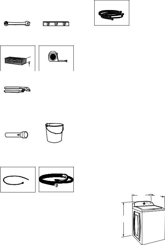
TOOLS AND PARTS
Gather required tools and parts before starting installation.
Tools needed:
|
|
|
Adjustable or open end |
|
Level |
wrench 9/16" (14 mm) |
|
|
4" min (102 mm) 
Wood block |
|
Ruler or measuring tape |
|
|
|
|
|
|
Pliers that open to 19⁄16" (39.5 mm)
Optional tools:
|
|
|
Flashlight |
|
Bucket |
Parts supplied:
NOTE: All parts supplied for installation are in cardboard insert in the top of the washer.
Parts needed: (Not supplied with washer)
Inlet hoses with flat washers
To order, please refer to toll-free phone numbers on back page of your Use and Care Guide.
■8212656RP 10 ft. (3.0 m) Inlet hose, Black EPDM (2 pack)
■8212641RP 5 ft. (1.5 m) Inlet hose, Black EPDM (2 pack)
■8212646RP 4 ft. (1.2 m) Inlet hose, Black EPDM (2 pack)
■8212545RP 5 ft. (1.5 m) Inlet hose, Red and Blue EPDM
(2 pack)
■8212487RP 5 ft. (1.5 m) Nylon braided inlet hose (2 pack)
■8212638RP 6 ft. (1.8 m) Nylon braided inlet hose, space
saving 90° elbow, hypro-blue steel couplings (2 pack)
■ 8212637RP 6 ft. (1.8 m) Inlet hose, Black EPDM, space saving 90° elbow, hypro-blue steel couplings (2 pack)
Alternate parts: (Not supplied with washer)
Your installation may require additional parts. To order, please refer to toll-free numbers on back page of your Use and Care Guide.
If you have: |
You will need: |
Overhead sewer |
Standard 20 gal. (76 L) 39" |
|
(990 mm) tall drain tub or utility |
|
sink, sump pump and connectors |
|
(available from local plumbing suppliers) |
1” (25mm) standpipe |
2” (51 mm) diameter to 1” (25 mm) |
|
diameter Standpipe Adapter Kit |
|
Part Number 280130 |
Drain hose too short |
Kit Part Number 280131 |
Lint clogged drain |
Drain protector, |
|
Part Number 367031 |
LOCATION REQUIREMENTS
Select proper location for your washer to improve performance and minimize noise and possible “washer walk”. Install your washer in a basement, laundry room, closet or recessed area.
Beaded Tie Strap |
Drain hose with clamp |
271/2" |
27" |
|
|
(648 mm) |
(686 mm) |
42" (1067 mm)
2-2
INSTALLATION REQUIREMENTS (continued)
You will need:
■A water heater set to 120° F (49° C).
■A grounded electrical outlet located within 4 ft (1.2 m) of power cord on back of washer.
■Hot and cold water faucets located within 3 ft (0.9 m) of hot
of 20-100 psi (138-690 kPa).
■
washer. Installing on carpet is not recommended.
■Floor must support washer’s total weight (with water and load) of 315 lbs (143 kgs).
IMPORTANT: Do not install, store or operate washer where it will be exposed to weather or in temperatures below 32° F
(0° C). Water remaining in washer after use may cause damage in low temperatures. See “Washer Care” in your Use and Care Guide for winterizing information.
Proper installation is your responsibility.
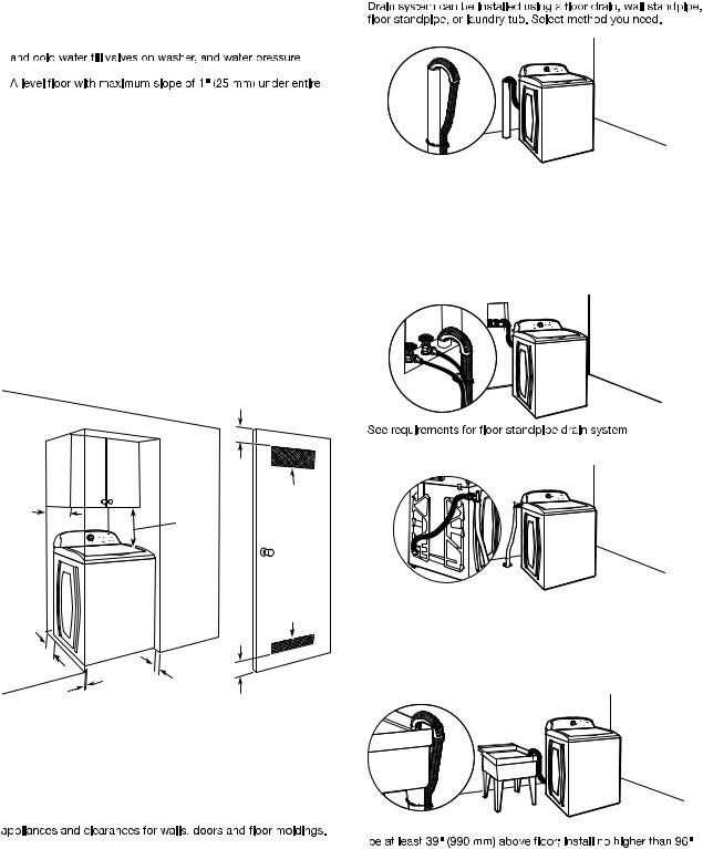
DRAIN SYSTEM
Floor standpipe drain system
Minimum diameter for a standpipe drain: 2" (51 mm). Minimum carry-away capacity: 17 gal. (64 L) per minute. Top of standpipe must be at least 39" (990 mm) high; install no higher than 96" (2.44 m) from bottom of washer. If you must install higher than 96" (2.44 m), you will need a sump pump system.
Wall standpipe drain system
3"
(76 mm)
14" max. |
48 in .2 |
(356 mm) |
(310 cm 2) |
|
17" |
|
(432 mm) |
24 in .2 5" (155 cm 2)
(126 mm)
|
1" |
3" |
1" |
(25 mm) |
|
(25 mm) |
|
(76 mm) |
Recessed area or closet installation
Dimensions show recommended spacing allowed, except for closet door ventilation openings which are minimum required. This washer has been tested for installation with spacing of 0" (0 mm) clearance on the sides. Consider allowing more space for ease of installation and servicing; spacing for companion
Add spacing of 1" (25 mm) on all sides of washer to reduce noise transfer. If a closet door or louvered door is installed, top and bottom air openings in door are required.
Floor drain system
Floor drain system requires a Siphon Break Kit (Part Number 280129) and additional drain hose (Part Number 3357090) that may be purchased separately. To order, please see toll-free phone numbers in your Use and Care Guide. Minimum siphon break: 28" (710 mm) from bottom of washer. (Additional hoses may be needed.)
Laundry tub drain system
Minimum capacity: 20 gal. (76 L). Top of laundry tub must
(2.44 m) from bottom of washer.
IMPORTANT: To avoid siphoning, no more than 4.5" (113 mm) of drain hose should be inside standpipe or below the top of wash tub. Secure drain hose with beaded tie strap.
2-3
INSTALLATION REQUIREMENTS (continued)
ELECTRICAL REQUIREMENTS |
INSTALLATION INSTRUCTIONS |
||||||||||
|
|
|
|
|
|
|
|
|
|
|
|
|
|
|
|
|
|
|
|
|
|
|
|
|
|
|
|
|
|
|
|
|
|
|
|
|
|
|
|
|
|
|
|
|
|
|
|
|
|
|
|
|
|
|
|
|
|
|
|
|
|
|
|
|
|
|
|
|
|
|
|
|
|
|
|
|
|
|
|
|
|
|
|
|
|
|
|
|
|
|
|
|
|
|
|
|
|
|
|
|
|
|
|
|
|
|
|
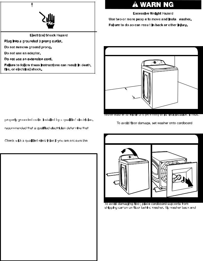
Before you start: remove shipping materials
It is necessary to remove all shipping materials for proper operation and to avoid excessive noise from washer.
■A 120 volt, 60 Hz., AC only, 15or 20-amp, fused electrical supply is required. A time-delay fuse or circuit breaker is recommended. It is recommended that a separate circuit breaker serving only this appliance be provided.
■This washer is equipped with a power supply cord having a 3 prong grounding plug.
■To minimize possible shock hazard, the cord must be plugged into a mating, 3 prong, grounding-type outlet, grounded in accordance with local codes and ordinances. If a mating outlet is not available, it is the personal responsibility and obligation of the customer to have the
■If codes permit and a separate ground wire is used, it is the ground path is adequate.
■Do not ground to a gas pipe.
■
washer is properly grounded.
■ Do not have a fuse in the neutral or ground circuit.
GROUNDING INSTRUCTIONS
For a gr ounded, cor d-connected washer:
This washer must be grounded. In the event of a malfunction or breakdown, grounding will reduce the risk of electrical shock by providing a path of least resistance for electric current. This washer is equipped with a cord having an equipment-grounding conductor and a grounding plug. The plug must be plugged into an appropriate outlet that is properly installed and grounded in accordance with all local codes and ordinances.
WARNING: Improper connection of the equipmentgrounding conductor can result in a risk of electric shock. Check with a qualified electrician or serviceman if you are in doubt as to whether the appliance is properly grounded.
Do not modify the plug provided with the appliance – if it will not fit the outlet, have a proper outlet installed by a qualified electrician.
For a permanentl y connected washer:
This washer must be connected to a grounded metal, permanent wiring system, or an equipment grounding conductor must be run with the circuit conductors and connected to the equipment-grounding terminal or lead on the appliance.
1. Move washer
36" |
(914 mm) |
be in a fully upright position.
NOTE:
before moving it and make sure lid is taped shut.
2. Remove shipping base
place on cardboard supports. Remove shipping base. Set washer upright.
IMPORTANT: Removing shipping base is necessary for proper operation. If your washer includes a sound shield, please refer to the instructions included with the sound shield to install it at this time.
2-4
INSTALLATION REQUIREMENTS (continued)
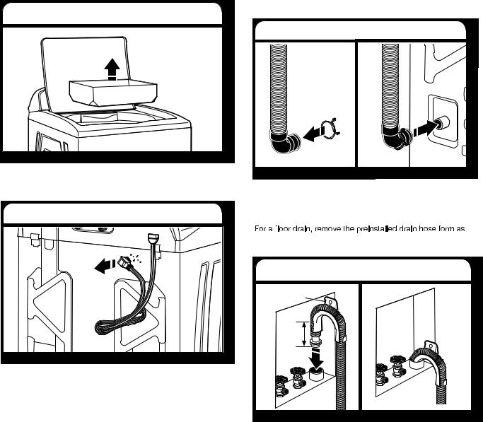
3. Remove packing tray from drum |
CONNECT DRAIN HOSE |
|
5. Attach drain hose to drain port |
Remove tape from washer lid, open lid and remove cardboard packing tray from tub. Be sure to remove all parts from tray.
NOTE: Keep tray in case you need to move washer later.
4. Free power cord
Firmly grasp power cord plug and pull to free from rear panel. Gently place power cord over console to allow free access to back of washer.
If clamp is not already in place on elbow end of drain hose, slide it over end as shown. Squeeze clamp with pliers and slide black elbow end of drain hose onto black drain port and secure with clamp.
For a laundry tub or standpipe drain, go to step 6.
shown in Step 7. You may need additional parts with separate directions. See “Tools and Parts”.
6. Place drain hose in standpipe
Drain hose form
4.5" (113 mm)
Place hose into standpipe (shown in picture) or over side of laundry tub.
IMPORTANT: 4.5" (113 mm) of drain hose should be inside standpipe; do not force excess hose into standpipe or lay on bottom of laundry tub. Drain hose form must be used.
2-5

INSTALLATION REQUIREMENTS (continued)
7. Remove drain hose form |
|
|
9. Clear water lines |
|
|
|
|
|
|
|
|
|
|
|
|
|
|
|
|
hose form from the end of the drain hose. You may need additional parts with separate directions. See “Tools and Parts”.
CONNECT INLET HOSES
Washer must be connected to water faucets with new inlet
inlet valves. If you are only connecting to a cold water faucet, you must use a Y-adapter (not provided).
8. Connect inlet hoses to water faucets
Attach hose to hot water faucet. Screw on coupling by hand until it is seated on washer. Use pliers to tighten couplings an additional two-thirds turn. Repeat this step with second hose for cold water faucet.
IMPORTANT: Do not overtighten or use tape or sealants on valve when attaching to faucets or washer. Damage can result.
HELPFUL TIP: Make note of which hose is connected to hot water to help in attaching hoses to washer correctly. In most
attached correctly.
Run water for a few seconds through hoses into a laundry tub, drainpipe or bucket to prevent clogs. Water should run until clear.
10. Connect inlet hoses to washer
Attach hot water hose to hot water inlet valve marked with a red ring. Screw coupling by hand until it is snug. Use pliers to tighten couplings an additional two-thirds turn. Repeat with cold water inlet valve.
IMPORTANT: To reduce risk of hose failure, replace the hoses every 5 years. Record hose installation or replacement dates for future reference.
■Periodically inspect and replace hoses if bulges, kinks, cuts, wear, or leaks are found.
11.Check for leaks
Turn on water faucets to check for leaks. A small amount of water may enter washer. It will drain later.
2-6
INSTALLATION REQUIREMENTS (continued)
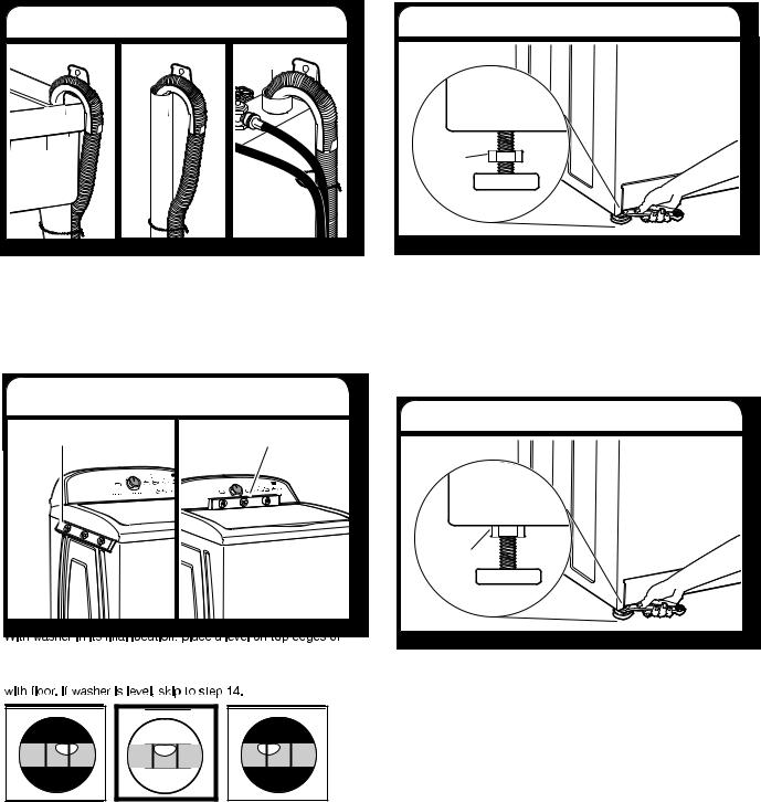
12. Secure drain hose |
|
Laundry Tub |
Standpipe Wall |
Secure drain hose to laundry tub leg, drain standpipe or inlet hoses for wall standpipe with beaded tie strap.
LEVEL WASHER
IMPORTANT: Level washer properly to reduce excess noise and vibration.
13. Check levelness of washer
Place level here |
Place level here |
washer. Use side seam as a guide to check levelness of sides. Check levelness of front using lid, as shown. Rock washer back and forth to make sure all four feet make solid contact
14. Adjust leveling feet
Jam nut |
If washer is not level, use a 9/16” or 14 mm open-end or adjustable wrench to turn jam nuts clockwise on foot until they are about 1/2” (13 mm) from the washer cabinet. Then turn the leveling foot clockwise to lower the washer or counterclock - wise to raise the washer. Recheck levelness of washer and repeat as needed.
HELPFUL TIP: You may want to prop up front of washer about 4” (102 mm) with a wood block or similar object that will support weight of washer.
15. Tighten leveling feet
Jam nut |
When washer is level, use a 9/16" or 14 mm open-end or adjustable wrench to turn jam nuts counterclockwise on leveling feet tightly against washer cabinet.
HELPFUL TIP: You may want to prop washer with wooden block.
Not Level |
LEVEL |
Not Level |
2-7
PRODUCT OPERATION
THEORY OF OPERATION
INTRODUCTION
The VMW Vertical Modular Washer represents several familiar features from prior designs. It utilizes and improves on the best systems from prior Whirlpool top load automatic washer designs and integrates them into this new design.
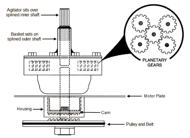
DRIVE SYSTEM
Motor – Bi-directional PSC (Permanent Split Capacitor) 120VAC. Agitation and variable spin speeds are accomplished by applying power in pulses.
Transmission – The transmission is a non-serviceable belt driven component.
-Inner shaft top splines connect to the agitator.
-Bottom splines connect to the splutch pulley.
-Outer shafts top splines connect to the basket.
-Bottom splines connect to the inner splines of the splutch cam.
3-1
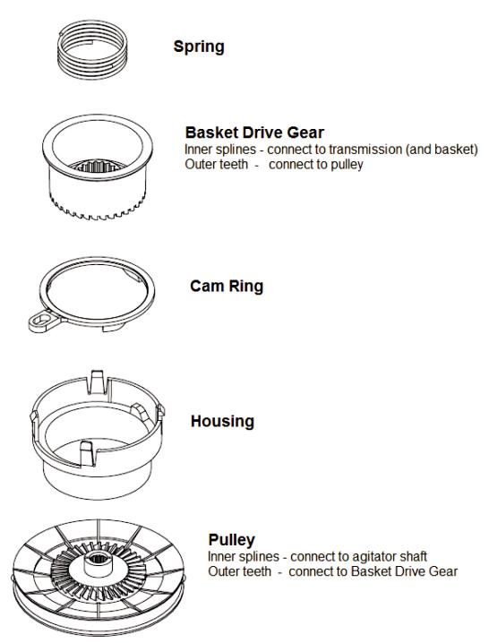
Splutch – The splutch is made up of five parts; a spring, housing, cam ring, basket drive gear and pulley. The pulley is connected to the agitator through the agitator shaft. The agitator always moves with the pulley. The basket drive gear is connected to the basket by the inner splines contacting the outer splines of the transmission. The cam ring raises and lowers the basket drive gear. When the basket drive gear teeth are engaged to the pulley teeth the basket will spin along with the agitator.
3-2
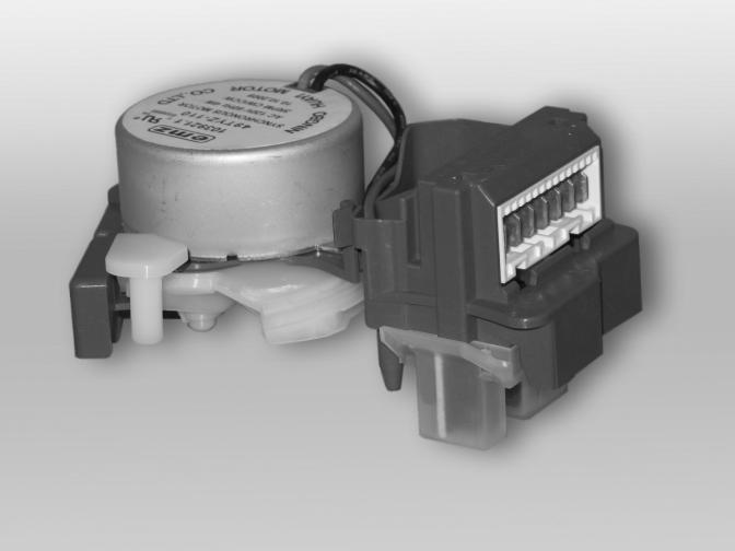
ACTUATOR
The actuator serves several functions. It has a synchronous motor that shifts the splutch slider and monitors the position of the splutch. It also houses a transmission speed/position optical sensor.
3-3
LID LOCK MECHANISM
Since this washer does not utilize a brake, a lid lock is used to
prevent access during use. During a cycle, a lid lock mechanism will lock the lid. The lid must be closed for the machine to fill, wash, drain, or spin. The mechanism houses a switch that senses that the lid is down, a latch solenoid and a switch to confirm that the lid is locked.
3-4

CONTROL PANEL AND FEATURES
ECO MONITOR
Your washer is specially designed to conserve energy and water. Each cycle, along with any selected options, will result in different energy and water usage. As you make your cycle and temperature selections, the
Eco Monitor shows how well you are saving energy and water.
WASH CYCLE KNOB
Use the Wash Cycle Knob to select available cycles on your washer. Turn the knob to select a cycle for your laundry load. See “Cycle Guide” for detailed descriptions of cycles.
CYCLE OPTIONS
When you select a cycle, its default settings will light up.
TEMP
Temperature Control senses and main tains uniform water temperatures by regulating incoming hot and cold water.
Select a wash temperature based on the type of fabric and soils being
washed. For best results and following the garment label instructions, use the warmest wash water safe for your fabric.
•Warmandhotwaterwillbecoolerthanwhat your previous washer provided.
•EveninCoolwash,somewarmwatermay be added to the washer to maintain a minimum temperature.
SOIL LEVEL
Soil level (wash time) is preset for each wash cycle. As you press Soil Level, the cycle time
(minutes) will increase or decrease in the Estimated Time Remaining display and a different wash time will appear.
For most loads, use the soil level that is preset with the cycle you have chosen. For heavily soiled and sturdy fabrics, press Soil Level to select more wash time, if needed. For lightly soiled and delicate fabrics, press
Soil Level to select less wash time, if needed. Lower soil level setting will help reduce tangling and wrinkling.
SPIN SPEED
This washer automatically selects the spin speed based on the cycle selected. The preset speeds can be changed. Not all spin speeds are available with all cycles.
• Faster spin speeds mean shorter dry times, but may
increase wrinkling in your load.
• Slower spin speeds mean less wrin kling, but will leave your load more damp.
You may also add or remove options for each cycle.
Note: that not all options can be used with all cycles, and some are preset to work with certain cycles.
3-5
CONTROL PANEL AND FEATURES (continued)
DEEP CLEAN
This option provides enhanced cleaning action for tough stains. It will add additional time to the cycle. Deep Clean should be started on a dry load only and must be selected before tub has started to fill.
DELAY WASH
If you would like to set your washer to start at a preferred time, select the Delay Wash
Option. You can use this option to delay start of a wash cycle for up to 10 hours (depending on model). Press Delay Wash button once to delay 1 hour. If you want a longer delay period, press and hold the button until your desired delay time (in hours) shows in the Estimated Time Remaining display. Then press START/PAUSE. The countdown to the wash cycle will show in the display window.
ECOBOOST
The EcoBoost option allows you to increase your energy savings on your wash cycles.
When this option is used, the wash cycle will use cooler wash water than the selected cycle and may increase the spin speed for faster drying.
PRESOAK
Use this option to add an extra soak period to any cycle when washing heavily soiled garments.
EXTRA RINSE
This option can be used to automatically add a second rinse to most cycles.
FABRIC SOFTENER
This option must be selected if using fabric softener during a cycle. It ensures that fabric softener is added at the correct time in the rinse for even distribution.
CYCLE SIGNAL
Use this option to adjust volume of the signal that sounds at end of cycle. A louder signal is helpful in removing items as soon as cycle is complete.
Press and hold Cycle Signal for 5 seconds to turn the button sounds off or on.
EST TIME REMAINING DISPLAY
The Estimated Time Remaining display shows the time required for the cycle to complete. Factors such as load size and water pressure may affect the time shown in the display. Overloading, unbalanced loads, or excessive suds may cause the washer to adjust the cycle time, as well.
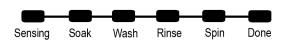
CYCLE STATUS LIGHTS INDICATOR
The Cycle Status Lights shows the progress of a cycle. At each stage of the process, you may notice sounds or pauses that are different from traditional washers.
SENSING
When the START button is pressed, the washer will first perform a self-test on the lid lock mechanism. You will hear a click, the basket will make a slight turn, and the lid will unlock briefly before locking again. Once the lid has locked the second time, the washer will slowly spin the dry load to estimate
the load size, and begin adding water. The washer will then move the load briefly, pause to allow water to soak in to the load, and resume adding water. This process may repeat until the correct amount of water has been added for the load. You may also hear water flowing through the dispenser, adding detergent to the load.
NOTE: The sensing light may also come on during the Soak and Wash portions of the cycle. This is normal.
3-6

CONTROL PANEL AND FEATURES (continued)
SOAK
This portion of the cycle allows water to soak into the load for optimal cleaning.
WASH
You will hear the impeller moving the load.
Unlike traditional washers, the load is not covered with water. Low-water cleaning means concentrated cleaning. Rather than diluting detergent as done in an agitator-style washer, this washer delivers the detergent directly to the soils. The motor sounds may change at different stages in the cycle. The wash time is determined by the selected soil level.
RINSE
You will hear sounds similar to the wash cycle as the washer rinses and moves the load. Fabric softener will be added if the Fabric Softener option was selected.
SPIN
The washer spins the load at increasing speeds for proper water removal, based on the selected cycle and spin speed.
DONE
Once the cycle is complete, this light will come on.
Remove the load promptly for best results.
LID LOCK
This light indicates that the lid is locked and cannot be opened.
If you need to open the lid, press START/
PAUSE. The lid will unlock once the washer movement has stopped. This may take
several minutes if the load was spinning at high speed. Press START/PAUSE again to restart the cycle.
3-7

CYCLE GUIDE
Settings and options shown in bold are default settings for that cycle.
If using the Eco Monitor, adjust the temperature and spin speed within that cycle to improve energy usage.
Not all cycles and options are available on all models.
Items to |
Cycle: |
Wash/Rinse |
Spin |
Soil |
Available |
Cycle Details: |
wash: |
|
Temperature: |
Speed: |
Level: |
Options: |
|
|
|
|
|
|
|
|
Machine-wash |
Delicates |
Hot/Cold |
High |
Extra Heavy |
Deep Clean |
Use this cycle to wash lightly soiled |
silks, hand- |
|
Warm/Cold |
Low |
Heavy |
Extra Rinse |
garments indicating “Machine Washable |
wash fabrics |
|
Cool/Cold |
No Spin |
Medium |
Delay Wash |
Silks” or “Gentle” cycle on the care label. |
|
|
Cold/Cold |
|
Light |
Eco |
Place small items in mesh garment bags |
|
|
Tap Cold/Cold |
|
|
Presoak |
before washing. |
Small loads, |
Quick |
Hot/Cold |
High |
Extra Heavy |
Deep Clean |
Use this cycle to wash small, lightly |
cottons, |
Wash |
Warm/Cold |
Low |
Heavy |
Extra Rinse |
soiled loads of 2-3 items that are needed |
polyester, |
|
Cool/Cold |
No Spin |
Medium |
Delay Wash |
in a hurry. |
perm press |
|
Cold/Cold |
|
Light |
Eco |
|
|
|
Tap Cold/Cold |
|
|
Presoak |
|
|
|
|
|
|
|
|
No-iron fabrics, |
Casual |
Hot/Cold |
High |
Extra Heavy |
Deep Clean |
Use this cycle to wash loads of no-iron |
cottons, perm |
|
Warm/Cold |
Low |
Heavy |
Extra Rinse |
fabrics such as sport shirts, blouses, |
press, linens, |
|
Cool/Cold |
No Spin |
Medium |
Delay Wash |
casual business clothes, permanent |
synthetics |
|
Cold/Cold |
|
Light |
Eco |
press, and blends. |
|
|
Tap Cold/Cold |
|
|
Presoak |
|
Cottons, linens, |
Normal |
Hot/Cold |
High |
Extra Heavy |
Deep Clean |
Use this cycle for normally soiled cottons |
and mixed |
|
Warm/Cold |
Low |
Heavy |
Extra Rinse |
and mixed fabric loads. |
garment loads |
|
Cool/Cold |
No Spin |
Medium |
Delay Wash |
|
|
|
Cold/Cold |
|
Light |
Eco |
|
|
|
Tap Cold/Cold |
|
|
Presoak |
|
Large items |
Bulky |
Hot/Cold |
High |
Extra Heavy |
Extra Rinse |
Use this cycle to wash large items such as |
such as sleeping |
Items |
Warm/Cold |
Low |
Heavy |
Delay Wash |
jackets and small comforters. The washer |
bags, small |
|
Cool/Cold |
No Spin |
Medium |
Eco |
load before the wash portion of the cycle |
comforters, |
|
Cold/Cold |
|
Light |
Presoak |
|
jackets |
|
Tap Cold/Cold |
|
|
|
begins. Do not overload basket. |
|
|
|
|
|
|
|
Sturdy fabrics, |
Heavy |
Hot/Cold |
High |
Extra Heavy |
Deep Clean |
Use this cycle for heavily soiled or |
colorfast items, |
Duty |
Warm/Cold |
Low |
Heavy |
Extra Rinse |
sturdy items. Water-level sensing process |
towels, lightly- |
|
Cool/Cold |
No Spin |
Medium |
Delay Wash |
may take longer for some items than for |
soiled colored |
|
Cold/Cold |
|
Light |
Eco |
others because they will absorb more |
clothing |
|
Tap Cold/Cold |
|
|
Presoak |
water than other fabric types. |
Heavily soiled |
Whites |
Hot/Cold |
High |
Extra Heavy |
Deep Clean |
Extra Rinse is a default option, but may be |
white fabrics |
|
Warm/Cold |
Low |
Heavy |
Extra Rinse |
turned off. For maximum soil removal use |
|
|
Cool/Cold |
No Spin |
Medium |
Delay Wash |
liquid chlorine bleach. |
|
|
Cold/Cold |
|
Light |
Eco |
|
|
|
Tap Cold/Cold |
|
|
Presoak |
|
Swimsuits |
Rinse & |
Hot/Cold |
High |
|
|
Combines a deep rinse and high speed |
|
Spin |
Warm/Cold |
Low |
|
|
spin for loads requiring an additional |
|
Cool/Cold |
No Spin |
|
|
rinse cycle or to complete a load after |
|
|
|
|
|
|||
|
|
Cold/Cold |
|
|
|
power interruption. |
|
|
Tap Cold/Cold |
|
|
|
Also use for loads that require rinsing only. |
|
|
|
|
|
|
|
ADDITIONAL CYCLES 
Drain & Spin
This cycle uses a high-speed spin to shorten drying times for heavy fabrics or special-care items. Use this cycle to drain washer after cancelling a cycle or completing a cycle after a power failure.
NOTE: Do not add detergents or bleach products when running this cycle.
Soak
Select Soil Level to adjust soaking cycle time. After time has expired, water will drain but washer will not spin.
NOTE: Automatic bleach dispensing is not part of soak cycle.
Clean Washer with AFFRESH ®
Use this cycle monthly to keep washer drum fresh and clean. Higher water levels combined with AFFRESH™ help eliminate odors and mildew. See Washer Maintenance for more details.
IMPORTANT: Make sure washer is empty before selecting this cycle.
3-8
USING THE WASHER
1. Sort and prepare your laundry
•Empty pockets. Loose change, buttons, or any small object can pass under the impeller and become trapped, causing unexpected sounds.
•Sort items by recommended cycle, water temperature, and colorfastness.
•Separate heavily soiled items from lightly soiled.
•Separate delicate items from sturdy fabrics.
•Do not dry garments if stains remain after washing, because heat can set stains into fabric.
•Treat stains promptly.
•Close zippers, fasten hooks, tie strings and sashes, and remove non-washable trim and ornaments.
•Mend rips and tears to prevent further damage to items during washing.
Helpful Tips:
•When washing water-proof or water-resistant items, load evenly. See “Cycle Guide” for tips and more information on using the Bulky Items cycle.
•Use garment bags to help prevent tangling when washing delicate or small items.
•Turn knits inside out to prevent pilling. Separate lint-takers from lint-givers. Synthetics, knits, and corduroy fabrics will pick up lint from towels, rugs, and chenille fabrics.
2. Load laundry into washer
 Recom mended maximum
 load height


Load garments in loose heaps evenly around basket wall. For best results, do not load higher than the recommended maximum load height. Try mixing different sized items to reduce tangling.
IMPORTANT: Do not overload washer. Items need to move freely. Overloading can lead to poor cleaning performance, and may increase wrinkling and tangling.
Always read and follow fabric care labels instructions to avoid damage to your garments.
3-9
 Loading...