


INSTALLATION INSTRUCTIONS
Commercial Dryer Gas or Electric
INSTRUCTIONS D’INSTALLATION
Sécheuse à usage commercial à gaz ou électrique
TABLE OF CONTENTS |
|
DRYER SAFETY........................................................................ |
2 |
TOOLS & PARTS ...................................................................... |
5 |
DIMENSIONS/CLEARANCES ................................................. |
6 |
GAS DRYER INSTALLATION REQUIREMENTS .................... |
7 |
ELECTRIC DRYER INSTALLATION REQUIREMENTS ........ |
10 |
DRYER VENTING REQUIREMENTS ..................................... |
13 |
GAS SUPPLY CONNECTION ................................................ |
15 |
INSTALLING LEVELING LEGS, COIN SLIDE, AND |
|
COIN BOX............................................................................... |
17 |
ELECTRIC DRYER ELECTRICAL CONNECTIONS ............. |
18 |
LEVELING .............................................................................. |
23 |
COMPLETE INSTALLATION ................................................. |
24 |
REVERSING DRYER DOOR SWING ..................................... |
25 |
CHANGING TO A 30OR 60-MINUTE TIMING CAM .......... |
26 |
MAINTENANCE INSTRUCTIONS ......................................... |
27 |
IF YOU NEED ASSISTANCE .................................................. |
27 |
WARRANTY............................................................................ |
28 |
TABLE DES MATIÈRES
.
SÉCURITÉ DE LA SÉCHEUSE ............................................ |
29 |
OUTILS ET PIÈCES ............................................................. |
32 |
DIMENSIONS/DISTANCES DE DÉGAGEMENT ................ |
33 |
EXIGENCES D’INSTALLATION POUR LA |
|
SÉCHEUSE À GAZ................................................................ |
34 |
EXIGENCES D’INSTALLATION POUR |
|
LA SÉCHEUSE ÉLECTRIQUE ............................................ |
37 |
EXIGENCES CONCERNANT L’ÉVACUATION |
|
DE LA SÉCHEUSE ............................................................... |
39 |
RACCORDEMENT À LA CANALISATION DE GAZ ............ |
41 |
INSTALLATION DES PIEDS DE NIVELLEMENT, |
|
DE LA GLISSIÈRE À MONNAIE ET DE LA |
|
CAISSE À MONNAIE ........................................................... |
43 |
NIVELLEMENT ...................................................................... |
44 |
ACHEVER L’INSTALLATION ................................................ |
45 |
INVERSION DU SENS D’OUVERTURE DE LA PORTE ...... |
46 |
INSTALLATION D’UNE CAME DE MINUTAGE |
|
DE 30 OU 60 MINUTES ........................................................ |
47 |
INSTRUCTIONS D’ENTRETIEN ........................................... |
48 |
SI VOUS AVEZ BESOIN D’ASSISTANCE ............................ |
48 |
GARANTIE.............................................................................. |
49 |
W10867001A |
|
W10867002A – SP |
www.whirlpoolcommerciallaundry.com |

DRYER SAFETY
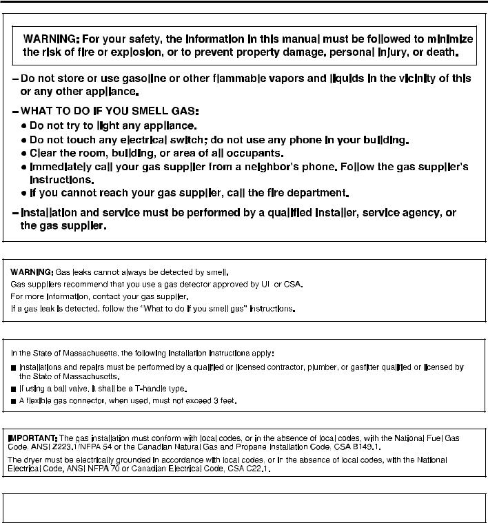
■■ It is recommended that the owner post, in a prominent location, instructions for the customer’s use in the event the customer smells gas. This information should be obtained from your gas supplier.
■■ Post the following warning in a prominent location.
2
DRYER SAFETY
IMPORTANT: When discarding or storing your old clothes dryer, remove the door.
3

DRYER SAFETY
IMPORTANT SAFETY INSTRUCTIONS
WARNING: To reduce the risk of fire, electric shock, or injury to persons when using the dryer, follow basic precautions, including the following:
■■ Read all instructions before using the dryer.
■■ This dryer is intended only for drying clothes and textiles that have been washed in water. Do not use for any other purpose.
■■ WARNING: If you smell gas, do not use the dryer or any electrical equipment nearby. Warn other people to clear the area. Contact the dryer owner immediately.
■■ Do not place items exposed to cooking oils in your dryer. Items contaminated with cooking oils may contribute to a chemical reaction that could cause a load to catch fire.
■■ Do not dry articles that have been previously cleaned in, washed in, soaked in, or spotted with gasoline, dry-cleaning solvents, other flammable, or explosive substances as they give off vapors that could ignite or explode.
■■ Do not dry unwashed items in the dryer.
■■ Do not allow children to play on or in the dryer. Close supervision of children is necessary when the dryer is used near children.
■■ Before the dryer is removed from service or discarded, remove the door to the dryer compartment.
■■ Do not reach into the dryer if the drum is moving.
■■ Do not open door while dryer is in operation. It will stop.
■■ Do not install or store the dryer where it will be exposed to water and/or the weather.
■■ Do not tamper with controls.
■■ Clean dryer lint screen before or after each load.
■■ Do not use this dryer without the lint screen in place.
■■ Do not repair or replace any part of the dryer or attempt any servicing unless specifically recommended in this Installation Instructions or in published user-repair instructions that you understand and have the skills
to carry out.
■■ Do not use fabric softeners or products to eliminate static unless recommended by the manufacturer of the fabric softener or product.
■■ Do not use heat to dry articles containing foam rubber or similarly textured rubber-like materials.
■■ The final part of a tumble dryer cycle occurs without heat (cool-down cycle) to ensure that the articles are left at a temperature that ensures that the items will not be damaged.
■■ WARNING: Never stop a tumble dryer before the end of the drying cycle unless all items are quickly removed and spread out so that the heat is dissipated. (Avoids risk of spontaneous combustion).
■■ Keep area around the exhaust opening and adjacent surrounding areas free from the accumulation of lint, dust, and dirt.
■■ The interior of the dryer and dryer exhaust vent should be cleaned periodically by qualified service personnel.
■■ See “Electrical Requirements” section for grounding instructions.
SAVE THESE INSTRUCTIONS
4

TOOLS & PARTS
Tools Needed:
8" (203 mm) |
8" (203 mm) or 10" (254 mm) |
Flat-Blade Screwdriver |
Phillips Screwdriver |
|
or 10" |
(254 mm) |
Adjustable Wrench |
|
|
Pipe |
Wrench |
that opens to 1" (25 mm) |
|
|
Torx®† T-20 Security |
1" (25 mm) Hex-Head |
5⁄16" (8 mm) Socket Wrench |
Pliers (that open to |
Screwdriver or Bit |
Socket Wrench |
|
19/16" [39 mm]) |
Level |
Utility Knife |
1/4" (6 mm) Nut Driver |
27" (686 mm) |
|
|
|
Wood Block |
Caulk Gun and Caulk |
Vent Clamps |
Pipe-Joint Compound |
Putty Knife |
(for installing new exhaust vent) |
|
Suitable for Gas Type |
|
Flashlight (optional) |
1" (25 mm) |
Ruler or Measuring Tape |
|
Open-End Wrenches |
|
Parts Supplied:
Foot Boots (4) |
Leveling Legs (4) |
Security Cone |
Service Door Lock Assembly |
|
|
(on some models) |
(on some models) |
5/16" Hex Head – |
3-Pin 60-Minute Timing Cam |
6-Pin 30-Minute Timing Cam |
18 x 2½" Security Bolt |
(on some models) |
(on some models) |
(on some models) |
|
|
|
25 25 25 |
|
|
|
$0.75 |
|
25 25 25 |
25 |
|
|
$1.00 |
|
25 25 25 25 |
25 |
|
|
$1.25 |
|
25 25 25 25 |
25 |
25 |
|
$1.50 |
|
25 25 25 25 |
25 |
25 |
25 |
$1.75 |
25 |
25 25 25 25 |
25 |
25 |
25 |
$2.00 |
Coin Slide Decal Kit
(on some models)
†® TORX and T25 are registered trademarks of Acument Intellectual Properties, LLC.
5

DIMENSIONS/CLEARANCES
Dimensions
Side View Back View
291/4"  (743 mm)
 26"
26"  (660 mm)
81/4" (210 mm)
35" |
|
(889 mm) |
|
|
31/4" |
|
(83 mm) |
|
71/2" |
1" |
(191 mm) |
(25 mm) |
|
|
27" |
|
|
|
|
(686 mm) |
|
|
|
|
Electric |
|
|
|
|
131/2" |
|
|
|
|
(343 mm) |
36" |
|
41" |
|
103/4" |
(914 mm) |
|
(1042 mm) |
11/2" |
(273 mm) (electric models) |
|
||
|
|
371/2" |
||
(38 mm) |
4" dia |
(953 mm) |
||
|
(102 mm) |
(gas models) |
||
51/2" |
Gas |
|
|
|
|
|
|
|
|
(140 mm) |
|
|
|
|
|
131/2" |
31/4" |
|
|
|
(343 mm) |
|
|
|
|
|
(83 mm) |
|
|
Clearances
Front View, Recessed Opening |
Side View, Recessed In Closet |
|
||
14" max |
|
14" max |
|
|
(356 mm) |
|
|
|
|
|
(356 mm) |
|
|
|
|
|
|
|
|
|
|
|
3"/3" |
|
|
|
|
(76 mm) 48"2/48"2 |
|
|
15" |
|
15" |
(310 cm2) |
|
(381 mm) |
|
(381 mm) |
|
|
|
|
|
24"2/24"2 |
|
|
|
3"/3" |
(155 cm2) |
|
|
|
(76 mm) |
|
0" |
|
0" |
|
|
(0 mm) |
0" |
(0 mm) |
1" |
|
|
|
(25 mm) |
|
|
0" |
(0 mm) |
|
|
|
0" |
Closet Door to |
|
||
|
|
|||
(0 mm) |
|
Front of Dryer |
|
|
|
(0 mm) |
|
||
|
|
|
|
|
6

GAS DRYER INSTALLATION REQUIREMENTS
Location Requirements
Your dryer can be installed in a basement, laundry room, or recessed area.
This dryer is not intended for installation in a mobile home.
Companion appliance location requirements should also be considered.
IMPORTANT: Do not install or store the dryer where it will be exposed to water and/or the weather. Proper installation is your responsibility.
You will need:
■■ A grounded electrical outlet located within 6 ft. (1.8 m) of where the power cord is attached to the back of the dryer. See “Electrical Requirements.”
■■ A level floor with a maximum slope of 1" (25 mm) under entire dryer. Installing the dryer on soft floor surfaces, such as carpets or surfaces with foam backing, is not recommended.
Gas dryer installation clearances
■■ The location must be large enough to allow the dryer door to be fully opened.
■■ Additional spacing should be considered for ease of installation and servicing. The door opens more than 180°.
■■ Additional clearances might be required for wall, door, and floor moldings.
■■ Additional spacing of 1" (25 mm) on all sides of the dryer is recommended to reduce noise transfer.
When installing a gas dryer:
IMPORTANT: Observe all governing codes and ordinances.
■■ Check code requirements: Some codes limit or do not permit installation of clothes dryers in garages, closets, or sleeping quarters. Contact your local building inspector.
■■ Make sure that lower edges of the cabinet, plus the back and bottom sides of the dryer, are free of obstructions to permit adequate clearance of air openings for combustion air. See “Recessed Area and Closet Installation Instructions” below for minimum spacing requirements.
Recessed Area and Closet Installation Instructions
This dryer may be installed in a recessed area or closet. For recessed area and closet installations, minimum clearances can be found on the warning label on the rear of the dryer or in “Dimensions/Clearances.”
The installation spacing is in inches and is the minimum allowable. Additional spacing should be considered for ease of installation, servicing, and compliance with local codes and ordinances.
If closet door is installed, the minimum unobstructed air opening in the top and bottom is required. The unobstructed opening needs to be 1 square inch per 1,000 Btu (252 kcal) of gas burner output. Output on North American gas dryers is typically 22,000 Btu; however, Canadian dryers may have lower output. Louvered doors with equivalent air openings are acceptable.
The dryer must be exhausted outdoors.
No other fuel-burning appliance may be installed in the same closet as the dryer.
48 in.2
(310 cm2) 3"
(76 mm)
|
|
|
Front |
|
Closet |
|
Closet |
|
View |
|
Door |
View |
|
door |
|
|
|
3" (76 mm)
24 in.2
(155 cm2)
7

GAS DRYER INSTALLATION REQUIREMENTS
Electrical Requirements
IMPORTANT: The dryer must be electrically grounded in accordance with local codes and ordinances or, in the absence of local codes, with the National Electrical Code, ANSI/NFPA 70, latest edition, or Canadian Electrical Code, CSA C22.1.
If codes permit and a separate ground wire is used, it is recommended that a qualified electrical installer determine that the ground path is adequate.
A copy of the above code standards can be obtained from:
National Fire Protection Association
One Batterymarch Park, Quincy, MA 02269
CSA International
8501 East Pleasant Valley Road
Cleveland, Ohio 44131-5575 ■■ Do not ground to a gas pipe.
■■ Do not have a fuse in the neutral or ground circuit.
■■ A 120 volt, 60 Hz, AC only, 15or 20-amp, fused electrical circuit is required. A time-delay fuse or circuit breaker is also recommended. It is recommended that a separate circuit serving only this dryer be provided.
■■ This dryer is equipped with a power supply cord having a 3-prong grounding plug.
■■ To minimize the possibility of shock, the cord must be plugged into a mating, 3 prong, grounding-type outlet, grounded in accordance with local codes and ordinances. If a mating outlet is not available, it is the personal responsibility and obligation of the customer to have the properly grounded outlet installed by a qualified electrician.
■■ If codes permit and a separate ground wire is used, it is recommended that a qualified electrician determine that the ground path is adequate.
■■ Check with a qualified electrician if you are not sure the dryer is properly grounded.
Gas Dryer Grounding
GROUNDING INSTRUCTIONS
■ For a grounded, cord-connected dryer:
This dryer must be grounded. In the event of malfunction or breakdown, grounding will reduce the risk of electric shock by providing a path of least resistance for electric current.
This dryer is equipped with a cord having an equipmentgrounding conductor and a grounding plug. The plug must be plugged into an appropriate outlet that is properly installed and grounded in accordance with all local codes and ordinances.
WARNING: Improper connection of the equipmentgrounding conductor can result in a risk of electric shock. Check with a quali•ed electrician or service representative or personnel if you are in doubt as to whether the dryer is properly grounded. Do not modify the plug provided with the dryer: if it will not •t the outlet, have a proper outlet installed by a quali•ed electrician.
SAVE THESE INSTRUCTIONS
8
GAS DRYER INSTALLATION REQUIREMENTS
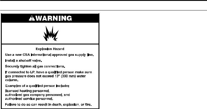
Gas Supply
IMPORTANT: Observe all governing codes and ordinances.
This installation must conform with all local codes and ordinances. In the absence of local codes, installation must conform with American National Standard, National Fuel Gas Code ANSI Z223.1/NFPA 54 or CAN/CSA B149.
A copy of the above code standards can be obtained from:
National Fire Protection Association
One Batterymarch Park, Quincy, MA 02269
CSA International
8501 East Pleasant Valley Road
Cleveland, Ohio 44131-5575
The design of this dryer has been certified by CSA International for use at altitudes up to 10,000 feet (3048 m) above sea level at the B.T.U. rating indicated on the model/serial plate. Burner input adjustments are not required when the dryer is operated up to this elevation.
When installed above 10,000 feet (3048 m), a four percent (4%) reduction of the burner B.T.U. rating shown on the model/ serial plate is required for each 1,000 foot (305 m) increase in elevation. For assistance when converting to other gas types and/or installing above 10,000 feet (3048 m) elevation, contact your local service company.
9
 Loading...