


Whirlpool CSP2770K, CSP2771K, CAE2761K, CAE2762K, CAE2792K Service Manual
...CONSUMER SERVICES TECHNICAL EDUCATION GROUP PRESENTS CL-7
ADVANTECH
COMMERCIAL LAUNDRY PRODUCTS
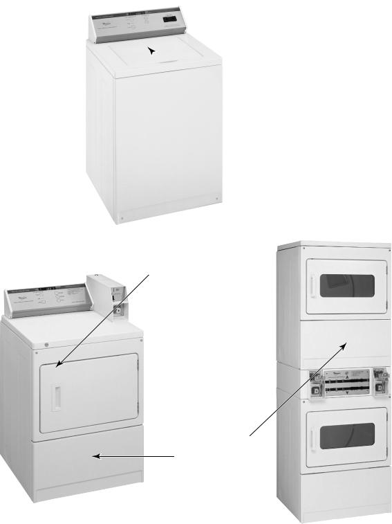
Washers
Metercase Equipped Models: # |
CAE2761K & CAE2762K |
Full Console Card Ready Model: # CAE2792K |
|
Freestanding Dryers |
|
Metercase Equipped Models: # |
CEE2760K & CGE2761K |
Full Console Card Ready Models: #CEE2790K & CGE2791K |
|
Stack Dryers |
|
Models: # |
CSP2770K & CSP2771K |
JOB AID
Part No. 8178077

FORWARD
This Whirlpool Job Aid, “ADVANTECH Commercial Laundry Products,” (Part No. 8178077), provides the technician with information on the installation, operation, and service of ADVANTECH Commercial Laundry Products. It is to be used as a training Job Aid and Service Manual. For specific information on the model being serviced, refer to the “Literature Pack” provided with ADVANTECH Commercial Laundry Products.
The Wiring Diagrams and Strip Circuits used in this Job Aid are typical and should be used for training purposes only. Always use the Wiring Diagram supplied with the product when servicing the unit.
GOALS AND OBJECTIVES
The goal of this Job Aid is to provide detailed information that will enable the service technician to properly diagnose malfunctions and repair Whirlpool ADVANTECH Commercial Laundry Products.
The objectives of this Job Aid are to:
•Understand and follow proper safety precautions.
•Successfully troubleshoot and diagnose malfunctions.
•Successfully perform necessary repairs.
•Successfully return the product to its proper operational status.
WHIRLPOOL CORPORATION assumes no responsibility for any repairs made on our products by anyone other than Authorized Service Technicians.
Copyright © July, 2004, Whirlpool Corporation, Benton Harbor, MI 49022
- ii -
TABLE OF CONTENTS
|
Page |
GENERAL............................................................................................................................................. |
1-1 |
Safety First ...................................................................................................................................... |
1-1 |
Model & Serial Number Designations ............................................................................................. |
1-2 |
Model & Serial Number Label And Literature Pack Locations ........................................................ |
1-3 |
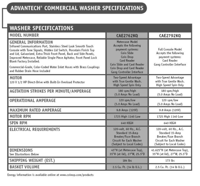
Specifications .................................................................................................................................. |
1-4 |
Washers ....................................................................................................................................... |
1-4 |
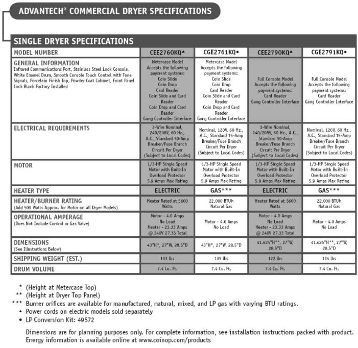
Freestanding Dryers .................................................................................................................... |
1-5 |
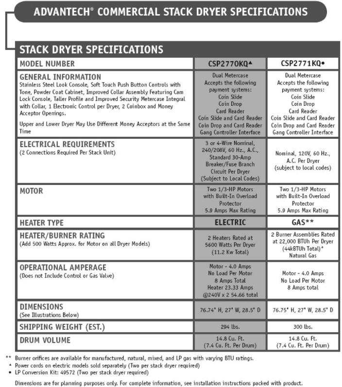
Stack Dryers................................................................................................................................. |
1-6 |
ADVANTECH Money Acceptor Cross Reference.......................................................................... |
1-7 |
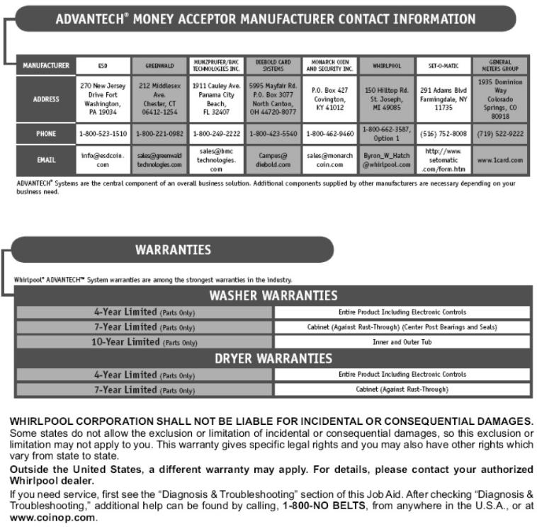
ADVANTECH Money Acceptor Manufacturer Contact Info/Warranty Info..................................... |
1-8 |
Literature Cross-Reference Chart ................................................................................................... |
1-9 |
INSTALLATION INFORMATION ......................................................................................................... |
2-1 |
Washers .......................................................................................................................................... |
2-1 |
Dryers .............................................................................................................................................. |
2-8 |
Money Acceptor Installation .......................................................................................................... |
2-25 |
PRODUCT OPERATION ...................................................................................................................... |
3-1 |
ADVANTECH System Overview ................................................................................................... |
3-1 |
ADVANTECH PC System & Palm Requirements ....................................................................... |
3-2 |
COMPONENT ACCESS....................................................................................................................... |
4-1 |
WASHERS ............................................................................................................................................ |
4-1 |
Washer Component Locations........................................................................................................ |
4-1 |
Removing The Console Components ............................................................................................. |
4-2 |
Removing The Money Acceptors & Metercase .............................................................................. |
4-6 |
Removing The Hidden Lid Switch ................................................................................................. |
4-10 |
Removing The Pump, Motor Start Capacitor, & Motor ................................................................. |
4-11 |
Removing The Agitator & Transmission ....................................................................................... |
4-13 |
Removing The Cabinet Assembly................................................................................................. |
4-16 |
Removing The Tub Ring, Basket, Outer Tub, And Basket Drive Assembly ................................. |
4-18 |
Removing The Suspension System & Base Assembly ................................................................ |
4-21 |
Removing The Vacuum Break ...................................................................................................... |
4-22 |
Removing The Dual Water Valve, Water Level Switch, And Drain Hose Assembly .................... |
4-23 |
DRYERS ............................................................................................................................................. |
4-25 |
Gas Dryer Component Locations.................................................................................................. |
4-25 |
Electric Dryer Component Locations ............................................................................................ |
4-25 |
Freestanding Dryers ........................................................................................................................... |
4-26 |
Removing The Console Components ........................................................................................... |
4-26 |
Removing The Money Acceptors & Metercase ............................................................................ |
4-29 |
Removing The Cabinet ................................................................................................................. |
4-33 |
Stack Dryers ....................................................................................................................................... |
4-35 |
Removing The Console Components ........................................................................................... |
4-35 |
Removing The Money Acceptors .................................................................................................. |
4-38 |
Removing The ADVANTECH Control Boards ............................................................................. |
4-40 |
Removing The Upper Dryer .......................................................................................................... |
4-41 |
Removing The Collar Assembly.................................................................................................... |
4-43 |
Freestanding And Stack Dryers .......................................................................................................... |
4-44 |
Removing The Door Switch .......................................................................................................... |
4-44 |
Removing The Thermal Fuse, Operating Thermostst, Drive Motor, & Broken Belt Switch .......... |
4-45 |
Removing The Heater, The High-Limit Thermostat, & Thermal Cutoff......................................... |
4-49 |
Removing The Burner Assembly, Flame Sensor, And High-Limit Thermostat............................. |
4-50 |
Removing The Belt, Drum, & Rollers ............................................................................................ |
4-53 |
Removing The Outlet Grille........................................................................................................... |
4-55 |
Removing A Spark Quencher ....................................................................................................... |
4-56 |
- iii -
COMPONENT TESTING ...................................................................................................................... |
5-1 |
Diagnostic Guide ............................................................................................................................. |
5-1 |
WASHERS ............................................................................................................................................ |
5-2 |
Motor ............................................................................................................................................... |
5-2 |
Motor Thermal Protector ................................................................................................................. |
5-3 |
Motor Start Capacitor ...................................................................................................................... |
5-3 |
Hidden Lid Switch ........................................................................................................................... |
5-4 |
Dual Water Valve ............................................................................................................................ |
5-4 |
Water Level Switch ......................................................................................................................... |
5-5 |
Basket Drive Shaft Checks ............................................................................................................. |
5-6 |
GAS & ELECTRIC DRYERS ................................................................................................................ |
5-7 |
Gas Burner Coils ............................................................................................................................. |
5-7 |
Burner Ignitor .................................................................................................................................. |
5-7 |
Flame Sensor .................................................................................................................................. |
5-8 |
High-Limit Thermostat ..................................................................................................................... |
5-8 |
Heater (Electric Models Only) ......................................................................................................... |
5-9 |
Drive Motor.................................................................................................................................... |
5-10 |
Thermal Fuse ................................................................................................................................ |
5-11 |
Operating Thermostat ................................................................................................................... |
5-12 |
Thermal Cutoff .............................................................................................................................. |
5-13 |
Door Switch ................................................................................................................................... |
5-14 |
DIAGNOSIS & TROUBLESHOOTING ................................................................................................ |
6-1 |
Diagnosis ........................................................................................................................................ |
6-1 |
Washers With Metercase ............................................................................................................. |
6-1 |
Freestanding Dryers Without Metercase ..................................................................................... |
6-8 |
Stack Dryers............................................................................................................................... |
6-13 |
WIRING DIAGRAMS & STRIP CIRCUITS ........................................................................................... |
7-1 |
Wiring Diagrams.............................................................................................................................. |
7-1 |
Washers ....................................................................................................................................... |
7-1 |
Freestanding Electric Dryers........................................................................................................ |
7-2 |
Freestanding Gas Dryers ............................................................................................................. |
7-3 |
Stack Electric Dryers .................................................................................................................... |
7-4 |
Stack Gas Dryers ......................................................................................................................... |
7-5 |
Dryer Strip Circuits .......................................................................................................................... |
7-6 |
CONTROL BOARD DIAGNOSTICS..................................................................................................... |
8-1 |
ADVANTECH WASHER PARTS........................................................................................................... |
9-1 |
SERVICE POINTERS....................................................................................................... |
Back Of Manual |
WHIRLPOOL COMMERCIAL LAUNDRY CONTACT INFO........................................ |
Inside Back Cover |
- iv -

GENERAL
SAFETY FIRST
Your safety and the safety of others is very important.
We have provided many important safety messages in this Job Aid and on the appliance. Always read and obey all safety messages.
This is the safety alert symbol.
This symbol alerts you to hazards that can kill or hurt you and others.
All safety messages will follow the safety alert symbol and either the word “DANGER” or “WARNING.” These words mean:
 DANGER
 WARNING
You can be killed or seriously injured if you don’t immediately follow instructions.
You can be killed or seriously injured if you don’t follow instructions.
All safety messages will tell you what the potential hazard is, tell you how to reduce the chance of injury, and tell you what can happen if the instructions are not followed.
1-1

MODEL & SERIAL NUMBER DESIGNATIONS
MODEL NUMBER
MODEL NUMBER |
C A E 27 6 1 K Q 0 |
|
|
PRODUCT GROUP
C = Commercial Laundry
PRODUCT IDENTIFICATION
A= Automatic Washer
E = Electric Dryer
G = Gas Dryer
S = Stack Dryer
CONTROL CODE
E = Electronic Control
M = Electromechanical
P = Pushbutton Single Unit or Stacked Pair
W = Resource Saver
FEATURE CODE
Cabinet Width in Inches (29″ or 27″)
FEATURE / VARIATIONS
4 = Metercase or Coinslide Equipped Stack W/O Windows
5 = Metercase and Coinslide Equipped
6 = Metercase or Coinslide Equipped Stack With Windows
7 = Card Reader Ready / Equipped Stacked Pair
9 = Full Width Console
FEATURE CODE
0 = Electric
1 = Single Speed or Gas
2 = Two Speed
YEAR OF INTRODUCTION
J = 2000, K = 2001, L = 2002, M = 2003, P = 2004, R = 2005, S = 2006
COLOR CODE
Q = White
ENGINEERING REVISION NUMBER
0 = Basic, 1 = 1st Revision, 2 = 2nd Revision
SERIAL NUMBER
SERIAL NUMBER |
C L 1 6 0 2 2 8 7 |
MANUFACTURING SITE |
|
C = Clyde, OH (Washers)
M = Marion, OH (Dryers)
YEAR OF PRODUCTION
L = 2001, M = 2002, N or P = 2003,
R = 2004, S = 2005, T = 2006
WEEK OF PRODUCTION
PRODUCT SEQUENCE NUMBER
1-2
MODEL & SERIAL NUMBER LABEL
AND LITERATURE PACK LOCATIONS
The Model & Serial Number label and Literature Pack locations are shown below. The Literature Pack includes a wiring diagram, parts list, and tech sheet.
WASHERS
 Model & Serial Number Label (located on the washer top rear center under the lid)
 Literature Pack
(located behind the front access panel)
STACK DRYERS
FREESTANDING DRYERS
Model & Serial Number  Label (located inside the
door jamb on the left side)
Literature Pack
(located behind the front access panel)
1-3
1- 4
1- 5
1- 6

1- 7
1- 8

LITERATURE CROSS-REFERENCE CHART
Archway |
Whirlpool |
|
|
|
|
Lit |
Part |
Description |
Contains |
Ordering & Viewing Information |
|
Number |
Number |
|
|
|
|
|
|
|
|
|
|
|
|
|
Parts breakdown, Wiring Diagram, |
|
|
N / A |
Model specific |
Product |
Tech Sheet, and Installation |
Available through Whirlpool Corporation |
|
Literature Pack |
Instructions. Packed with all |
Literature Department 1-800-851-4605 |
|||
|
|
||||
|
|
|
Whirlpool ADVANTECH products |
also available online: |
|
|
|
|
|
www.cltpsc.whirlpoolcorp.com |
|
|
|
PC User’s |
Complete Palm handheld application, |
products and more, |
|
N / A |
8524745 |
PC Management Software CD and |
Commercial Laundry link |
||
Assembly |
|||||
|
|
Software Manual |
- |
||
|
|
|
|||
N / A |
8178077 |
Service Manual/ |
Complete Diagnostic & Technical |
|
|
Job Aid |
Reference manual |
|
|||
|
|
|
|||
|
|
|
|
Available at www.coinop.com, or call |
|
|
|
|
|
1-800-643-3444. |
|
CWLL086 |
8524743 |
PC User’s Guide |
Complete Palm handheld application, |
Also available through Whirlpool |
|
Corporation Literature Department |
|||||
(Software Manual) |
PC Management Software Manual |
||||
|
|
and for selected Trade Partners at |
|||
|
|
|
|
||
|
|
|
|
www.cltpsc.whirlpoolcorp.com, |
|
|
|
|
|
products and more, Commercial |
|
|
|
|
|
Laundry link, or call |
|
CWLX043 |
8524744 |
Software Install CD |
Management Software CD only |
1-800-851-4605 |
|
|
|||||
|
|
|
|
|
|
CWLL082b |
N / A |
Sales Literature |
Product Specifications, Installation |
Available at www.coinop.com, or call |
|
Instructions, & Energy Usage |
1-800-643-3444 |
||||
|
|
|
Model |
Wiring |
Service |
Tech Sheet |
Installation |
Number |
Diagram |
Parts List |
(Technical Data) |
Instructions |
|
|
|
|
|
CAE2761K |
8524730B |
8524726 |
8524734 |
8524739 |
|
|
|
|
|
CAE2762K |
8524731B |
8524727 |
8524734 |
8524739 |
|
|
|
|
|
CAE2792K |
8524731B |
8524729 |
8524738 |
8524742 |
|
|
|
|
|
CGE2761K |
8527854D |
8527804 |
8527808 |
8527809 |
|
|
|
|
|
CEE2790K |
8527859C |
8527805 |
8527811 |
8527810 |
|
|
|
|
|
CEE2760K |
8527854D |
8527803 |
8527808 |
8527809 |
|
|
|
|
|
CGE2791K |
8527859C |
8527806 |
8527811 |
8527810 |
|
|
|
|
|
CSP2770K |
8527882A* |
8527819 |
8527886 |
8527892 |
|
|
|
|
|
CSP2771K |
8527882A* |
8527819 |
8527886 |
8527892 |
|
|
|
|
|
*CSP Stack Dryers have a wiring diagram label (#8527883A) on the upper dryer toe panel in addition to the diagram in the Literature Pack.
1-9
— NOTES —
1-10
WASHER
2-1
Washer Installation Instructions
 WARNING
Electrical Shock Hazard
Disconnect power before servicing.
Replace all parts and panels before operating.
Failure to do so can result in death or electrical shock.
BEFORE YOU START
Check location where washer will be installed. Proper installation is your responsibility. Make sure you have everything necessary for correct installation.
Untape and open washer lid. Remove packages and hoses from washer.
Single washer installations require 30 cm (12 inch) minimum risers to provide an air cushion and prevent noise and damage to valves.
Grounded electrical outlet is required. See “Washer Electrical Requirements” on page 2-3.
#T-20 Torx
Screws
On coin-operated washers, front access to the pump area is available by removing the two #T-20 Torx screws and then removing the front panel.
Important: Observe all governing codes and ordinances.
Level Floor:
Maximum slope under washer is 2.5 cm (1 inch).
A floor drain should be provided under the bulkhead. Prefabricated bulkheads with electrical outlets, water supply lines, and drain facilities should be used only where local codes permit.
Hot and cold water faucets must be within 1.2 meters (4 feet) of the back of the washer and provide water pressure 690 kPa (10-100 PSI). A pressure reduction valve should be used in the supply line where inlet pressure entering the building exceeds 690 kPa (100 PSI) to prevent damage to the washer mixing valve.
NOTE: Water Heater—Set to deliver 60°C to 70°C (140°F to 160°F) water to the washer.
Standpipe drain system: Needs a 5 cm (2 inch) minimum carry-away capacity of 64.4 liters (17 gallons) per minute. Top of standpipe must be at least 86.4 cm (34 inches) high
and no higher than 183 cm (72 inches) from bottom of washer.
Support: Floor must be sturdy enough to support loaded washer weight of 143 Kg (315 pounds).
2-2

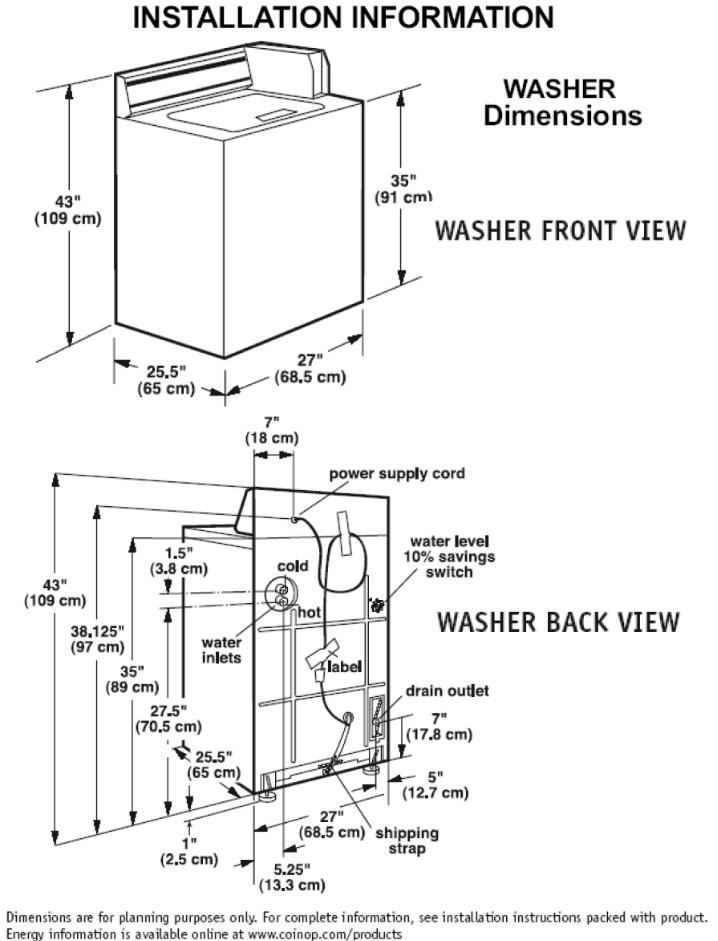
RECESSED AREA INSTRUCTIONS
This washer may be installed in a recessed area or a closet. The installation dimensions shown are the minimum spaces allowable. Additional spacing should be considered for ease of installation and servicing. If the closet door is installed, the minimum air openings at the top and bottom of the door are required. Louvered doors with air openings in the top and bottom are acceptable. Companion appliance spacing should be considered.
TOOLS NEEDED FOR
INSTALLATION
Level |
Pliers |
Wrench
Flat-Blade
Utility Screwdriver
Knife
Scissors
PARTS SUPPLIED FOR
INSTALLATION
1 Hose Clamp
2 Inlet Hoses
4 Flat Washers
2 Front Leveling Legs W/Nuts
1 Drain Hose
WASHER ELECTRICAL
REQUIREMENTS
 WARNING
Electrical Shock Hazard
Plug into a grounded 3-prong outlet.
Do not remove ground prong.
Do not use adapter.
Do not use an extension cord.
Failure to follow these instructions can result in death, fire, or electrical shock.
2-3
If codes permit and a separate ground wire is used, it is recommended that a qualified electrician determine that the ground path is adequate.
Do Not ground to a gas pipe.
Check with a qualified electrician if you are not sure the washer is properly grounded.
Do Not have a fuse in the neutral or ground circuit.
A 120-volt, 60-Hz, AC-only, 15or 20-ampere fused electrical supply is required. (Timedelay fuse or circuit breaker is recommended.) It is recommended that a separate circuit serving only this appliance be provided.
Grounding Instructions
For the safety of the customer, this washer must be grounded. The washer is equipped with a power supply cord that has a 3-prong grounding plug.
3-Prong GroundingType Outlet
3-Prong Grounding Plug
Ground
Power Supply Prong
Cord
To minimize a possible shock hazard, the cord must be plugged into a mating 3-prong ground- ing-type receptacle, which has been grounded in accordance with National Electrical Code (ANSI/NFPA 70), and all local and state codes.
If a mating outlet is not available, it is the personal responsibility and obligation of the customer to have a properly grounded 3-prong outlet installed by a qualified electrician.
IMPORTANT: Improper connection of the equipment-grounding conductor can result in a risk of electric shock. Do not modify the plug provided with the appliance. If it will not fit the outlet, have a proper outlet installed by a qualified electrician.
INSTALLING THE WASHER
 WARNING
Excessive Weight Hazard
Use two or more people to move and install washer.
Failure to do so can result in back or other injury.
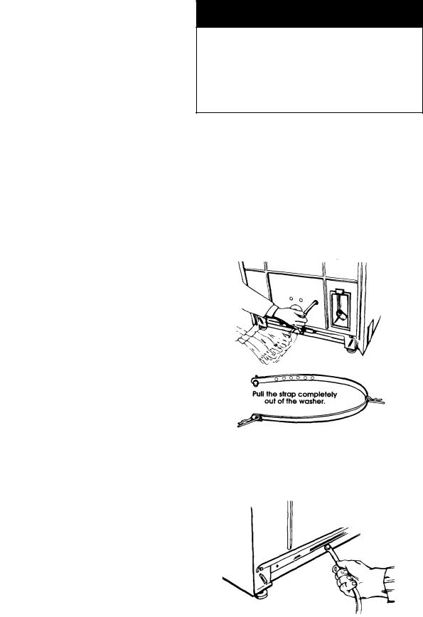
Removing the shipping strap is necessary for smooth operation. If the shipping strap is not removed,thewasherwillmakeexcessivenoise.
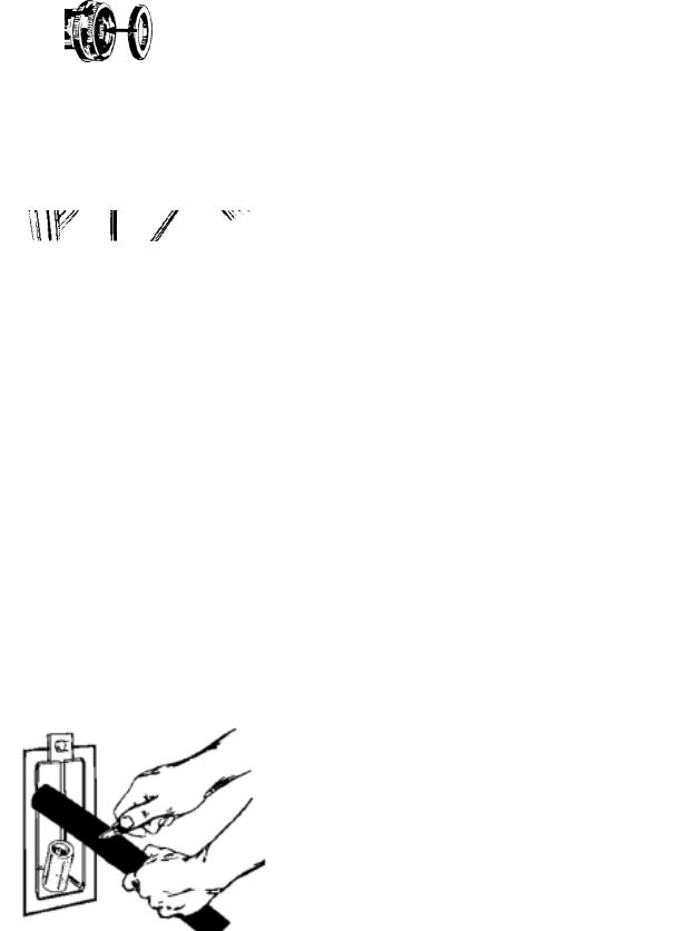
1.Do not cut yellow strap. Pull yellow strap firmly, until completely removed from washer. There will be two cotter pins on the end of the shipping strap when it is pulled out of the washer. The electrical plug is attached to this shipping strap.
2.The shipping strap plug must be completely removed from the washer for the self-level- ing legs to be released. Save the shipping strap for use in step 7.
2-4
3.Insert a flat washer into each end of the inlet hoses. Check that washers are firmly seated in couplings.
4.Attach hose to bottom inlet valve opening first. Then second hose to top inlet. Tighten couplings by hand; then use pliers to make an additional two-thirds turn. Slide washer onto cardboard or hardboard before moving across floor.
Inlets are plastic.
Do not strip or crossthread.
5.Move washer close to final position. Put the “hooked” end of drain hose into the standpipe. Estimate length of drain hose needed when washer is in final position. Hose must be cut exactly to length so the “hooked” end is held tightly over edge of standpipe. If drain hose is too long, cut straight end of hose. (Do not cut the “hooked” end of drain hose.) Do not force excess length of drain hose down the standpipe. This could cause siphoning. See step 8.
6.Place hose clamp over washer drain connector. Push drain hose onto washer connector. Use pliers to open clamp and slide clamp over drain hose. Check for good fit.
7.Measure and mark a point approximately 16″ (40.6 cm) from the plug end of the shipping strap. Cut the shipping strap at this point.
40.6cm
8.Put the “hooked” end of drain hose into the standpipe. Tightly wrap the shipping strap around the standpipe. Push plug into the nearest hole in the shipping strap. Check that hose is not twisted or kinked and is securely in place.
2-5

9.Beforeattachingwaterinlethoses,runwater through both faucets into a bucket. This will get rid of particles in water lines that might clog hoses. Mark which is the hot water faucet.
10.Attach bottom hose (inlet marked “H”) to hot water faucet. Attach top (inlet marked “C”) to cold water faucet. Tighten coupling to faucet by hand, then use pliers to make final two-thirds turn.
11.Prop up the front of the washer about 4″ (10.2 cm) with a wood block, or similar object. The block needs to support the weight of the washer.
12.Screw the locknut onto each foot to within 1″ (2.5 cm) of the base.
13.Screw the feet into the correct holes at the front corner of the washer until the nuts touch the washer. NOTE: Do not tighten the nuts until the washer is level, step 17.
14.Tilt washer backward and remove the wood block. Gently lower washer to floor. Move washer to its permanent location. Remove cardboard or hardboard from under washer.
15.Tilt washer forward raising back legs 1″ (2.5 cm) off of floor. To adjust rear leveling legs, gently lower washer to floor.
2.5 cm
(1″)
2-6
16.Check washer level by placing a level on top of the washer, first side-to-side, then front-to-back.
17.If washer is not level, adjust the front legs up or down. Make final check with level. Best results are obtained when the washer is tilted 1/4 bubble toward the rear and level side- to-side.Whenwasherislevel,usewrenchtoturn nuts on front legs up tightly against washer base.Ifnutsarenottightagainstwasherbase, the washer may vibrate.
18.Check that all parts are now installed. If there is an extra part, go back through steps to see which step was skipped.
19.Turn on water faucets and check for leaks. Tighten couplings if there is leaking. Do not over tighten; this could cause damage to faucets.
20.Check that you have all of your tools. Check that the shipping strap with 2 cotter pins and plug was removed from the back of the washer and used to secure the drain hose. If entire strap is not removed, washer may vibrate and be noisy.
21.Untape power supply cord.
22.Plug into a grounded 3-prong outlet.
23.Install the chosen money acceptor per the instructions under the appropriate money acceptor section of this Job Aid.
MOVING THE WASHER
To move the washer to a new location, perform the following steps:
1.Remove the front legs from the base of the washer.
2.Place both rear leveling legs in the upper position and tape them securely in place.
3.Apply tape to the side and bottom of the cabinet near the rear.
4.Open the washer lid, wedge a blanket between the tub ring and the cabinet top to keep the tub from moving.
5.Move the washer to the desired location. Be careful not to drop the washer while using a hand truck.
Wedge blanket between tub ring and cabinet top
Remove front legs
Tape rear |
Tape 2 |
legs in “up” |
sides |
position |
|
Hidden 
Lid Switch
NOTE: Do not place blanket in this area to protect hidden lid switch
2-7
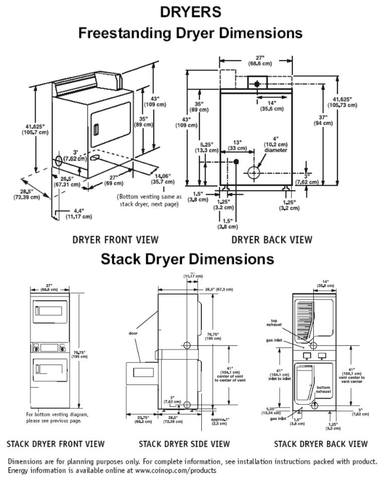
2-8

Dryer Installation Instructions
GAS REQUIREMENTS
 WARNING
Explosion Hazard
Use a new AGAor CSA-approved gas supply line.
Install a shutoff valve.
Securely tighten all gas connections.
If connected to L.P. have a qualified person make sure gas pressure does not exceed 13″ (33 cm) water column.
Examples of a qualified person include licensed heating personnel, authorized gas company personnel, and authorized service personnel.
Failure to do so can result in death, explosion, or fire.
Observe all governing codes and ordinances.
1.This installation must conform with local codes, or in absence of local codes with the National Fuel Gas Code ANSI Z223.1/NFPA 54ortheCAN/CGA-B149installationcodes.
2.The design of this dryer has been certified by the CSA International for use at altitudes up to 10,000 feet (3048 m) above sea level, at the BTU rating indicated on the model/ serial plate.
Burner input adjustments are not required when the dryer is operated up to this elevation. When installed above 10,000 feet (3048 m), a four percent (4%) reduction of the burner BTU rating shown on the model/serial plate isrequiredforeach1,000foot(305m)increase in elevation.
For assistance when converting to other gas types and/or installing above 10,000 feet (3048 m) elevation, contact your local service company.
3.Check that dryer is equipped with the correct burner for the particular type of gas used. Burner information can be found on the serial/rating plate in the door well of the appliance. If this information does not agree with the type of gas available, see your dealer.
4.This dryer is equipped for use with NATURAL GAS. It is certified by CSA International for manufactured, mixed and L.P. (propane and butane) gases with appropriate conversion. No attempt shall be made to convert the appliance from the gas specified on the serial/rating plate for use with a different gas without consulting the serving gas supplier. A qualified service technician must do conversion. Gas conversion kit part numbers are listed on the gas valve burner base.
5.Provide a rigid gas supply line of 1/2″ IPS pipe to the dryer location. If the total length of the supply line is more than 20 feet (6.1 m),
larger pipe will be needed. For L.P. gas usage, 3/8″ approved copper tubing may be used. Pipejoint compounds suitable for use with LP gas should be used.
2-9
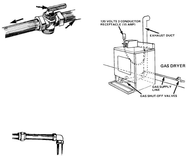
6.The supply line shall be equipped with a shutoff valve installed within 6 feet (1.8 m) of dryer in accordance with the American National Standard National Fuel Gas Code, ANSI Z223.1—latest edition*. In Canada, an individual manual shutoff valve must be installed in accordance with the B149 installation codes CAN/CGA B149.1 and CAN/CGA B149.2**. This valve should be located in the same room as the dryer and should be in a location that allows ease of opening and closing. Do not block access to the shutoff valve.
shutoff valve
“open” position
to dryer
gas supply line
7.If the dryer is installed in a confined area such as a bathroom or closet, provision must be made for enough air for combustion and ventilation. Check governing codes and ordinances.
8.If local codes and ordinances permit, it is recommended that new flexible metal tubing, design-certified by the AGA or CSA, be used for connecting the dryer to the gas supply line. (The gas feed pipe which ex-
tends through the lower rear of the dryer is provided with 3/8″ metal pipe thread.)
9.If rigid pipe is used as a gas supply line, a combination of pipefittings must be used to obtain an in-line connection to the dryer.
rigid pipe
10.Make sure that the lower edges of the cabinet, plus the back and bottom sides of the dryer are free of obstructions to permit adequate clearance of air openings for combustion air (see page 2-8 for minimum spacing requirements).
11.For ease of installation, operation and servicing (if ever needed) adequate space should be provided around the dryer.
12.A 1/8″ NPT plugged tapping, accessible for gauge testing, must be installed immediately upstream of the gas supply connection to the dryer. The dryer must be disconnected from the gas supply piping system during any pressure testing of the system at test pressures in excess of 1/2 psig. The dryer must be isolated from the gas supply piping system by closing the equipment shutoff valve during any pressure testing of the gas supply piping system at test pressures equal to or less than 1/2 psi (3.45 kPa).
Copies of the standards listed above may be obtained from:
*American Gas Association 1515 Wilson Blvd. Arlington, Virginia 22209
**CSA International
8501 East Pleasant Valley Road Cleveland, Ohio 44131-5575
2-10

ELECTRICAL REQUIREMENTS
 WARNING
Electrical Shock Hazard Plug into a grounded 3-prong outlet.
Do not remove ground prong.
Do not use an adapter.
Do not use an extension cord.
Failure to follow these instructions can result in death, fire, or electrical shock.
Observe all governing codes and ordinances.
If codes permit and a separate ground wire is used, it is recommended that a qualified electrician determine that the ground path is adequate.
A 120-volt, 60-Hz, AC-only, 15or 20-ampere fused electrical supply is required. A timedelay fuse or circuit breaker is recommended. It is recommended that a separate circuit serving only this appliance be provided.
The dryer, when installed, must be electrically grounded in accordance with local codes, or in the absence of local codes, with the National Electrical Code, ANSI/NFPA 70*, or the Canadian Electrical Code, CSA C22.1**
Copies of the standards listed above may be obtained from:
*National Fire Protection Association One Batterymarch Park
Quincey, Massachusetts 02269
**CSA International
8501 East Pleasant Valley Road Cleveland, Ohio 44131-5575
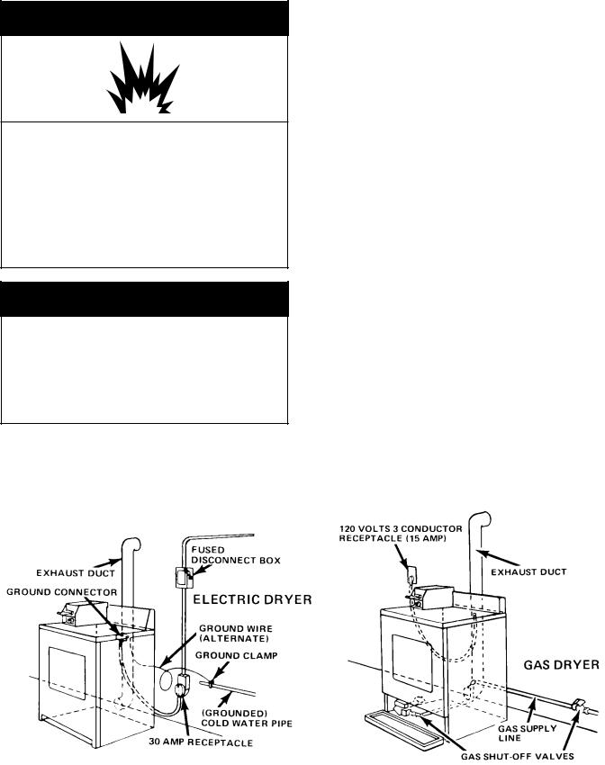
Grounding Instructions
This appliance must be grounded. In the event of malfunction or breakdown, grounding will reduce the risk of electric shock by providing a path of least resistance for electric current. The power supply cord plug must be plugged into an appropriate outlet that is properly installed and grounded in accordance with all local codes and ordinances.
3-Prong GroundingType Outlet
3-Prong
Grounding
Plug
Ground
Power Supply Prong
Cord
IMPORTANT: Improper connection of the equipment-grounding conductor can result in a risk of electric shock. Check with a qualified electrician or serviceman if you are in doubt as to whether the appliance is properly grounded. Do not modify the plug provided with the appliance. If it will not fit the outlet, have a proper outlet installed by a qualified electrician.
2-11

DRYER EXHAUST REQUIREMENTS
 WARNING
Fire Hazard
Use a heavy metal vent.
Do not use a plastic vent.
Do not use a metal foil vent.
Failure to do so can result in death or fire.
1.Do not use a non-metal flexible vent, a metal vent that is smaller than four inches in diameter, or exhaust hoods with magnetic latches.
2.The dryer must be exhausted outdoors.
3.Do not exhaust the dryer into a gas vent, chimney, wall, ceiling, or the concealed space of a building.
4.Do not install flexible vent in enclosed walls, ceilings, or floors.
5.If using an existing exhaust system, clean the lint from the entire length of exhaust system. Make sure the exhaust hood is not pluggedwithlint.Theexhaustsystemshould be inspected and cleaned yearly. Replace any plastic or metal foil exhaust vent with rigid metal, or flexible metal vent.
6.4″ (10.2 cm) metal exhaust vent is required.
Plan the installation to use the fewest number of elbows and turns. Use 4″ (10.2 cm) vent clamps to secure the vent system.
7.A metal flexible vent must be fully extended and supported when the dryer is in its final position. DO NOT KINK OR CRUSH THE
VENT.
8.A metal flexible vent must be completely open to allow adequate exhaust air to flow.
9.Allow as much room as possible when using elbows or making turns. Bend vent gradually to avoid kinking. Remove any excess flexible vent to avoid sagging and kinking that may result in reduced airflow. The exhaust outlet is located at the center of the bottom dryer back. The exhaust vent can be routed up, down, left, right, and behind the dryer, or straight out the back.
exhaust airflow
better |
good |
|
exhaust |
||
exhaust |
||
airflow |
||
airflow |
||
|
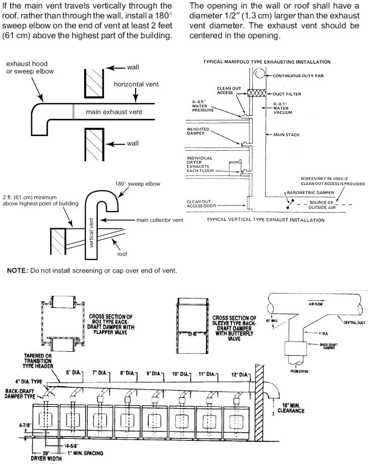
2-12
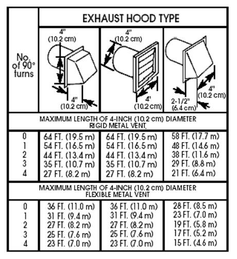
The maximum length of an exhaust system depends upon the type of vent used, the number of elbows, and the type of exhaust hood. The maximum lengths for both rigid and flexible venting is shown in the chart below.
For exhaust systems not covered by the exhaust length chart, see the Whirlpool Service Manual: “Exhausting Whirlpool Dryers,” Part No. 603197, which is available from your Whirlpool parts distributor. Also refer to Section 8.
If a dryer is installed in a confined area, it must be exhausted to the outside, and provision made for enough air for combustion and ventilation. Check governing codes and ordinances.
A 4″ (10.2 cm) outlet hood is preferred, however, a 2 1/2″ (6.4 cm) outlet exhaust hood may be used. A 2 1/2″ (6.4 cm) outlet creates greater backpressure than other hood types. For permanent installation, a stationary exhaust system is required.
2-13
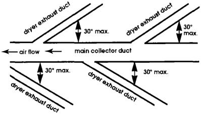
MULTIPLE DRYER VENT
INSTALLATION
A main exhaust vent can be used for exhausting a group of dryers. The main exhaust vent should be sized to remove 200 CFM of air per dryer.
Large-capacity lint screens of proper design may be used in the main exhaust vent if checked and cleaned frequently.
The room where the dryers are located should have makeup air equal to or greater than the CFM of all the dryers in the room.
An exhaust hood should cap the exhaust vent to prevent exhausted air from returning into the dryer. The outlet of the hood must be at least 12″ (30.5 cm) from the ground or anything else that may restrict flow of exhaust air. If an exhaust hood cannot be used, the outside end of the main vent should have a sweep elbow directed downward.
A Back-draft Damper Kit, #3391910, is available from your Whirlpool dealer and should be installed in each dryer's exhaust vent to prevent exhausted air from returning into the dryers, and to keep individual exhausts in balance within the main exhaust vent. Unobstructed air openings are required.
Each exhaust vent should enter the main vent at an angle pointing in the direction of the airflow.
Vents entering from the opposite side should be staggered to reduce the exhausted air from interfering with the other vents. The maximum angle of each vent entering the main vent should be no more than 30 degrees. Keep air openingsfreeofdrycleaningfluidfumes.Fumes create acids which, when drawn through the dryer heating units, can damage dryers and loads being dried. A clean-out cover should be located on the main exhaust vent for periodic cleaning of the exhaust system.
2-14
Whirlpool
Pt #3391910
2-15
INSTALLING THE DRYER
 WARNING
Explosion Hazard
Keep flammable materials and vapors, such as gasoline, away from dryer.
Place dryer at least 18 inches (45.8 cm) above the floor for a garage installation.
Failure to do so can result in death, explosion, or fire.
 WARNING
Excessive Weight Hazard
Use two or more people to move and install dryer.
Failure to do so can result in back or other injury.
1.Remove the tape from the front corners of the dryer. Open the dryer and remove the literature and parts packages. Wipe the interior of the drum thoroughly with a damp cloth.
2.Place two of the cardboard corners from the carton on the floor in back of the dryer. Firmly grasp the body of the dryer, and gently lay it on its back on the cardboard corners.
3.Look at the ridges on one of the leveling legs for a diamond marking. That is how far the leg is supposed to go into the hole.
4.Start to screw the leveling legs into the holes by hand. (You can use a small amount of liquid detergent to lubricate the screw
threads so it is easier to turn the legs.) Use a 1″ wrench or socket wrench to finish turning the legs until you reach the diamond mark, then stand dryer up on its feet.
NOTE: Slide the cardboard or hardboard under the dryer before moving it across any flooring, to avoid damaging the floor covering.
5.Move the dryer close to its final position. Remove the cardboard or hardboard from under the dryer.
At this time, proceed to either “Gas Dryers” or “Electric Dryers” to complete the installation.
2-16
 Loading...