


CSP2940HQ
Table of contents
 Loading...
TABLE OF CONTENTS
DRYER SAFETY ............................................................................2
TOOLS & PARTS ...........................................................................5
DIMENSIONS/CLEARANCES ...................................................6
LOCATION REQUIREMENTS ....................................................7
GAS DRYER ELECTRICAL REQUIREMENTS .......................8
GAS REQUIREMENTS ...............................................................9
ELECTRIC DRYER ELECTRICAL
REQUIREMENTS (U.S.A. ONLY) ............................................10
DRYER VENTING REQUIREMENTS ......................................12
INSTALLING LEVELING LEGS .................................................15
LEVELING ......................................................................................16
GAS SUPPLY CONNECTION ...................................................16
ELECTRIC DRYER ELECTRICAL
CONNECTIONS (FOR U.S.A. ONLY) .....................................18
COMPLETE INSTALLATION .....................................................24
REVERSING DRYER DOOR SWING (OPTIONAL) ............25
MAINTENANCE INSTRUCTIONS ...........................................26
IF YOU NEED ASSISTANCE ....................................................26
ELECTRONIC CONTROL SETUP INSTRUCTIONS ............27
WARRANTY ..................................................................................32
INSTALLATION
INSTRUCTIONS
Commercial Stacked
Dryer Gas (120 V, 60 Hz)
or Electric
(120/240 V, 60 Hz)
www.whirlpoolcommerciallaundry.com
W11255762A
W11255763A-SP
DRYER SAFETY
It is recommended that the owner post, in a prominent location, instructions for the customer’s use in the event the customer smells gas.
■
This information should be obtained from your gas supplier.
Post the following warning in a prominent location.
■
2
DRYER SAFETY
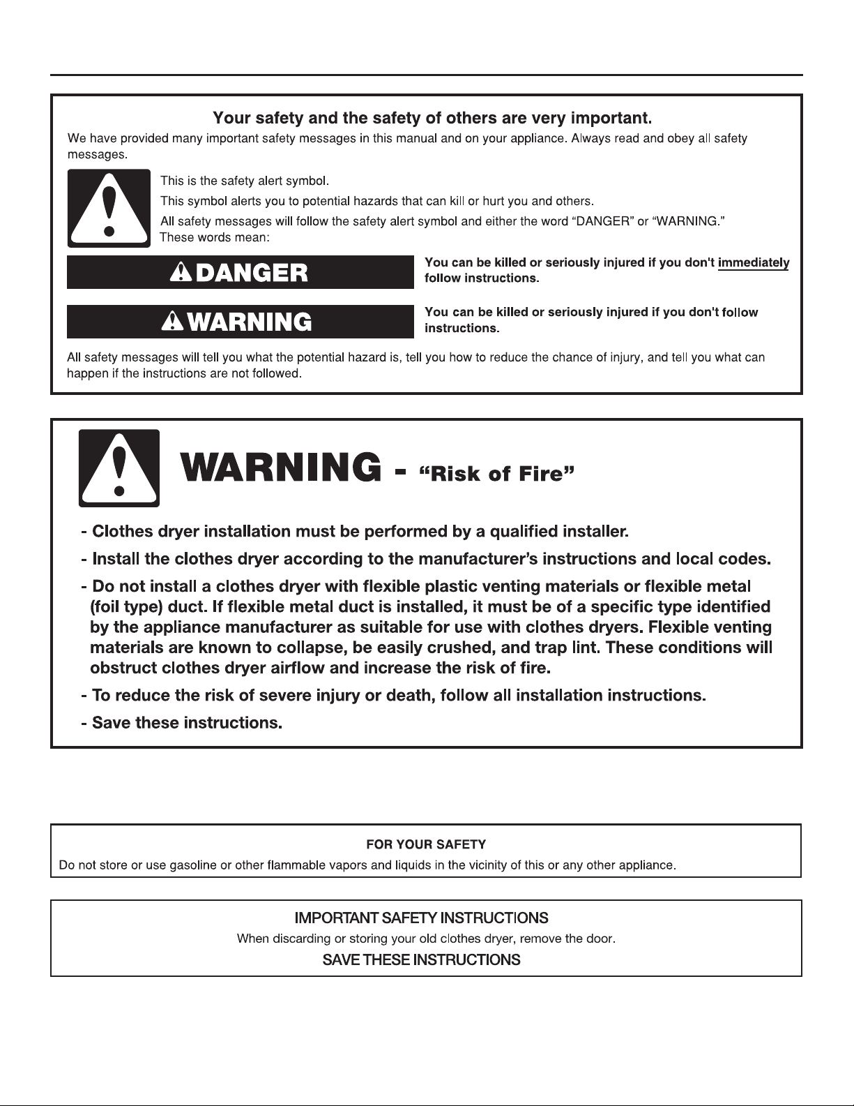
WARNING:
FIRE OR EXPLOSION HAZARD
Failure to follow safety warnings exactly could result in serious injury, death or property
damage.
–
Do not store or use gasoline or other flammable vapors and liquids in the vicinity of this
or any other appliance.
–
WHAT TO DO IF YOU SMELL GAS:
Do not try to light any appliance.
•
Do not touch any electrical switch; do not use any phone in your building.
•
Clear the room, building, or area of all occupants.
•
Immediately call your gas supplier from a neighbor's phone. Follow the gas supplier's
•
instructions.
If you cannot reach your gas supplier, call the fire department.
•
–
Installation and service must be performed by a qualified installer, service agency, or
the gas supplier.
In the State of Massachusetts, the following installation instructions apply:
■ Installations and repairs must be performed by a qualified or licensed contractor, plumber, or gas fitter qualified or licensed by
the State of Massachusetts.
■ Acceptable Shut-off Devices: Gas Cocks and Ball Valves installed for use shall be listed.
■ A flexible gas connector, when used, must not exceed 4 feet (121.9 cm).
IMPORTANT: The gas installation must conform with local codes, or in the absence of local codes, with the National Fuel Gas
Code, ANSI Z223.1/NFPA 54, or the Natural Gas and Propane Installation Code, CSA B149.1.
The dryer must be electrically grounded in accordance with local codes, or in the absence of local codes, with the National
Electrical Code, ANSI/NFPA 70, or the Canadian Electrical Code, Part 1, CSA C22.1.
3

DRYER SAFETY
IMPORTANT SAFETY INSTRUCTIONS
WARNING: To reduce the risk of fire, electric shock, or injury to persons when using the dryer, follow basic precautions, including the
following:
Read all instructions before using the dryer.
■
This dryer is intended only for drying clothes and textiles
■
that have been washed in water. Do not use for any other
purpose.
WARNING: If you smell gas, do not use the dryer or any
■
electrical equipment nearby. Warn other people to clear the
area. Contact the dryer owner immediately.
Do not place items exposed to cooking oils in your dryer.
■
Items contaminated with cooking oils may contribute to a
chemical reaction that could cause a load to catch fire. To
reduce the risk of fire due to contaminated loads, the final
part of a tumble dryer cycle occurs without heat (cool down
period). Avoid stopping a tumble dryer before the end of the
drying cycle unless all items are quickly removed and spread
out so that the heat is dissipated.
Do not dry articles that have been previously cleaned in,
■
washed in, soaked in, or spotted with gasoline, dry-cleaning
solvents, other flammable, or explosive substances as they
give off vapors that could ignite or explode.
Do not dry unwashed items in the dryer.
■
Do not allow children to play on or in the dryer. Close
■
supervision of children is necessary when the dryer is used
near children.
Before the dryer is removed from service or discarded,
■
remove the doors to the dryer compartment.
Do not reach into the dryer if the drum is moving.
■
Do not open door while dryer is in operation. It will stop.
■
Do not install or store the dryer where it will be exposed to
■
water and/or the weather.
Do not tamper with controls.
■
Clean dryer lint screen before or after each load.
■
Do not use this dryer without the lint screen in place.
■
Do not repair or replace any part of the dryer or attempt any
■
servicing unless specifically recommended in this Installation
Instructions or in published user-repair instructions that you
understand and have the skills to carry out.
Do not use fabric softeners or products to eliminate static
■
unless recommended by the manufacturer of the fabric
softener or product.
Do not use heat to dry articles containing foam rubber or
■
similarly textured rubber-like materials.
The final part of a tumble dryer cycle occurs without heat
■
(cool-down cycle) to ensure that the articles are left at a
temperature that ensures that the items will not be damaged.
WARNING: Never stop a tumble dryer before the end of
■
the drying cycle unless all items are quickly removed and
spread out so that the heat is dissipated. (Avoids risk of
spontaneous combustion).
Keep area around the exhaust opening and adjacent
■
surrounding areas free from the accumulation of lint, dust,
and dirt.
The interior of the dryer and dryer exhaust vent should be
■
cleaned periodically by qualified service personnel.
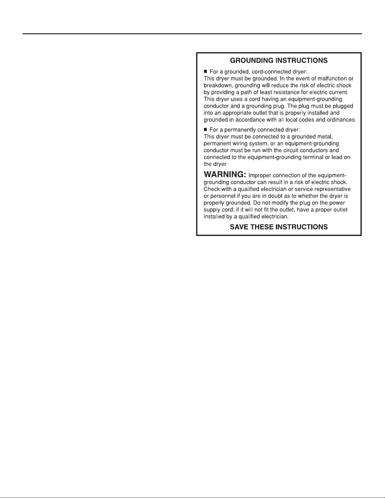
See “Electrical Requirements” section for grounding
■
instructions.
SAVE THESE INSTRUCTIONS
4
TOOLS & PARTS
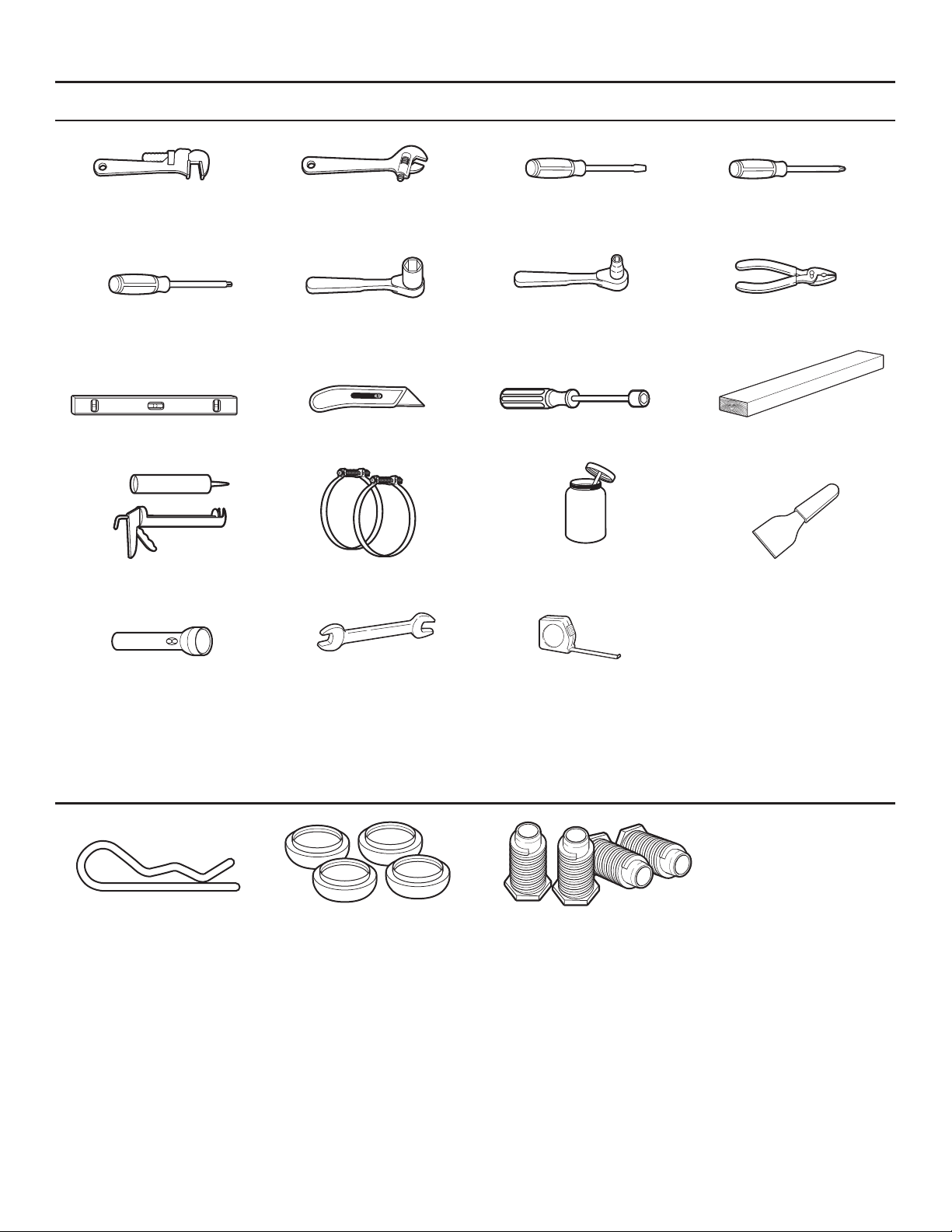
Tools Needed:
8" (200 mm) 8" (200 mm) or 10" (250 mm) Flat-blade screwdriver Phillips screwdriver
or 10" (250 mm) Adjustable wrench
Pipe wrench that opens to 1" (25 mm)
TORX® T20®† security 1" (25 mm) Hex-head 5/16" (8 mm) Socket wrench Pliers (that open to
screwdriver or bit socket wrench 19/16" [39 mm])
Level Utility knife 1/4" (6 mm) Nut driver 27" (686 mm)
Wood block
Caulk gun and caulk Vent clamps Pipe-joint compound Putty knife
(for installing new exhaust vent) suitable for gas type
Flashlight (optional) 1" (25 mm) Ruler or measuring tape
Open-end wrenches
Parts Supplied:
Security cotter pins (2) Foot Boots (4) Leveling Legs (4)
†®
TORX and T20 are registered trademarks of Acument Intellectual Properties, LLC.
5
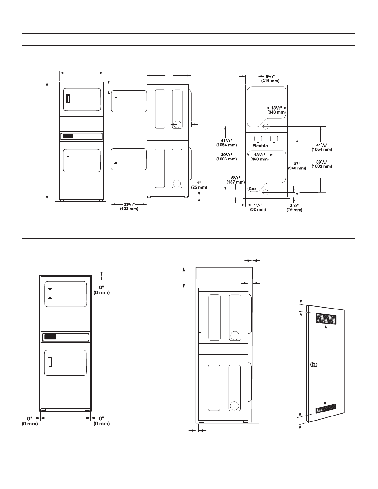
DIMENSIONS/CLEARANCES
Front View, Recessed Opening Side View, Recessed In Closet
Dimension:
Front View Side View Back View
763/4"
(1950 mm)
PD Models
(1950 mm
Coin Models
1
/4"
74
(1886 mm)
Non-Coin /
Card-Ready
Models
27"
(686 mm)
)
5"
(127 mm)
29"
(737 mm)
1
10
/
"
2
(267 mm)
Coin Models
Non-Coin /
Card-Ready
Models
Coin Models
Non-Coin /
Card-Ready Models
Minimum Clearance:
12"
(300 mm)
0"
(0 mm)
2 ¼
(57 mm)
"
Closet Door Minimum
Acceptable Vent Sizes
3"
(76 mm)
76mm)
3"
3"/3"
(76 mm)
48 inches
(310 cm )
310 cm
24 inches
(155 cm )
2
)
1"
(25 mm)
Closet door
to front of dryer
6
WARNING
Explosion Hazard
Keep flammable materials and vapors, such as
gasoline,away from dryer.
Do not install in a garage.
Failure to do so can result in death,explosion, or fire.
Your dryer can be installed in a basement, laundry room,
or recessed area.
This dryer is not intended for installation in a mobile home or
recreational vehicle.
Companion appliance location requirements should also be
considered.
IMPORTANT: Do not install or store the dryer where it will be
exposed to water and/or the weather. Proper installation is your
responsibility.
LOCATION REQUIREMENTS
When installing a gas dryer:
IMPORTANT: Observe all governing codes and ordinances.
Check code requirements: Some codes limit or do not permit
■
installation of clothes dryers in garages, closets,
or sleeping quarters. Contact your local building inspector.
Make sure that lower edges of the cabinet, plus the back and
■
bottom sides of the dryer, are free of obstructions to permit
adequate clearance of air openings for combustion air. See
“Recessed Area Installation Instructions” below for minimum
spacing requirements.
Recessed Area Installation Instructions
This dryer may be installed in a recessed area. For recessed area
installations, minimum clearances can be found on the warning label
on the rear of the dryer or in “Dimensions/Clearances.”
The installation spacing is in inches and is the minimum allowable.
Additional spacing should be considered for ease of installation,
servicing, and compliance with local codes and ordinances.
The dryer must be exhausted outdoors.
No other fuel-burning appliance may be installed in the same closet
as the dryer.
You will need:
A grounded electrical outlet located within 6 ft. (1.8 m) of
■
where the power cord is attached to the back of the dryer.
See “Electrical Requirements.”
A level floor with a maximum slope of 1" (25 mm) under entire
■
dryer. Installing the dryer on soft floor surfaces, such as carpets
or surfaces with foam backing, is not recommended.
Dryer installation clearances
The location must be large enough to allow the dryer door to be
■
fully opened.
Additional spacing should be considered for ease of installation
■
and servicing. The door opens more than 180°.
Additional clearances might be required for wall, door, and floor
■
moldings.
Additional spacing of 1" (25 mm) on all sides of the dryer is
■
recommended to reduce noise transfer.
7
GAS DRYER ELECTRICAL REQUIREMENTS
Gas Dryer Grounding
IMPORTANT: The dryer must be electrically grounded in
accordance with local codes and ordinances or, in the absence
of local codes, with the National Electrical Code, ANSI/NFPA 70,
latest edition, or Canadian Electrical Code, CSA C22.1. If codes
permit and a separate ground wire is used, it is recommended that
a qualified electrical installer determine that the ground path is
adequate.
A copy of the above code standards can be obtained from:
National Fire Protection Association
One Batterymarch Park, Quincy, MA 02269
CSA International
8501 East Pleasant Valley Road
Cleveland, Ohio 44131-5575
Do not ground to a gas pipe.
■
Do not have a fuse in the neutral or ground circuit.
■
A 120 V, 60 Hz, AC-only, 15 or 20 A, fused electrical circuit
■
is required. A time-delay fuse or circuit breaker is also
recommended. It is recommended that a separate circuit serving
only this dryer be provided.
If codes permit and a separate ground wire is used, it is
■
recommended that a qualified electrician determine that the
ground path is adequate.
Check with a qualified electrician if you are not sure the dryer is
■
properly grounded.
8
Gas Supply
WARNING
Explosion Hazard
Use a new CSA International approved gas supply line.
Install a shut-off valve.
Securely tighten all gas connections.
If connected to propane, have a qualified person make
sure gas pressure does not exceed 13" (33 cm) water
column.
Examples of a qualified person include:
licensed heating personnel,
authorized gas company personnel, and
authorized service personnel.
Failure to do so can result in death, explosion, or fire.
GAS REQUIREMENTS
IMPORTANT: Observe all governing codes and ordinances.
This installation must conform with all local codes and ordinances.
In the absence of local codes, installation must conform with
American National Standard, National Fuel Gas Code ANSI
Z223.1/NFPA 54 or CAN/CSA B149.
A copy of the above code standards can be obtained from:
National Fire Protection Association
One Batterymarch Park, Quincy, MA 02269
CSA International
8501 East Pleasant Valley Road
Cleveland, Ohio 44131-5575
The design of this dryer has been certified by CSA International
for use at altitudes up to 10,000 feet (3048 m) above sea level at
the B.T.U. rating indicated on the model/serial plate. Burner input
adjustments are not required when the dryer is operated up to this
elevation.
When installed above 10,000 feet (3048 m), a four percent (4%)
reduction of the burner B.T.U. rating shown on the model/serial
plate is required for each 1,000 feet (305 m) increase in elevation.
For assistance when converting to other gas types and/or installing
above 10,000 feet (3048 m) elevation, contact your local service
company.
9
ELECTRIC DRYER ELECTRICAL REQUIREMENTS (U.S.A. ONLY)
It is your responsibility:
To contact a qualified electrical installer.
■
To be sure that the electrical connection is adequate and in
■
conformance with the National Electrical Code, ANSI/NFPA
70-latest edition and all local codes and ordinances.
The National Electrical Code requires a 4-wire power supply
■
connection for homes built after 1996, dryer circuits involved in
remodeling after 1996, and all mobile home installations.
A copy of the above code standards can be obtained from:
■
National Fire Protection Association, One Batterymarch Park,
Quincy, MA 02269.
To supply the required 3- or 4-wire, single phase, 120/240 V,
■
60 Hz., AC-only electrical supply (or 3- or 4-wire, 120/208 V
electrical supply, if specified on the serial/rating plate) on a
separate 30 A circuit, fused on both sides of the line. A time
delay fuse or circuit breaker is recommended. Connect to an
individual branch circuit. Do not have a fuse in the neutral or
grounding circuit.
Do not use an extension cord.
■
If codes permit and a separate ground wire is used, it is
■
recommended that a qualified electrician determine that the
ground path is adequate.
Electrical Connection
To properly install your dryer, you must determine the type of
electrical connection you will be using and follow the instructions
provided for it here.
This dryer is manufactured ready to install with a 3-wire electrical
■
supply connection. The neutral ground conductor is permanently
connected to the neutral conductor (white wire) within the dryer.
If the dryer is installed with a 4-wire electrical supply connection,
the neutral ground conductor must be removed from the external
ground connector (green screw), and secured under the neutral
terminal (center or white wire) of the terminal block. When the
neutral ground conductor is secured under the neutral terminal
(center or white wire) of the terminal block, the dryer cabinet is
isolated from the neutral conductor.
If local codes do not permit the connection of a neutral ground
■
wire to the neutral wire, see “Optional 3-wire connection”
section.
A 4-wire power supply connection must be used when the
■
appliance is installed in a location where grounding through the
neutral conductor is prohibited. Grounding through the neutral
is prohibited for (1) new branch-circuit installations and (2)
areas where local codes prohibit grounding through the neutral
conductor.
Electric Dryer Grounding
10
ELECTRIC DRYER ELECTRICAL REQUIREMENTS (U.S.A. ONLY)
WARNING
Electric Dryer Power Supply Cord
Fire Hazard
Use a new UL listed 30 amp power supply cord.
Use a UL listed strain relief.
Disconnect power before making electrical connections.
Connect neutral wire (white or center wire) to center
terminal.
Ground wire (green or bare wire) must be connected to
green ground connector.
Connect remaining 2 supply wires to remaining
2 terminals.
Securely tighten all electrical connections.
Failure to do so can result in death, fire, or
electrical shock.
If using a power supply cord:
Use a UL Listed power supply cord kit marked for use with clothes
dryers. The kit should contain:
A UL Listed 30 A power supply cord, rated 120/240 V minimum.
■
The cord should be type SRD or SRDT and be at least
4 ft. (1.22 m) long. The wires that connect to the dryer must end in
ring terminals or “U” shaped spade terminals with upturned ends.
A UL Listed strain relief.
■
Direct Wire
WARNING
Fire Hazard
Use 10 gauge copper wire.
Use a UL listed strain relief.
Disconnect power before making electrical connections.
Connect neutral wire (white or center wire) to center
terminal.
Ground wire (green or bare wire) must be connected to
green ground connector.
Connect remaining 2 supply wires to remaining
2 terminals.
Securely tighten all electrical connections.
Failure to do so can result in death, fire, or
electrical shock.
If connecting by direct wire:
Direct wire cable must match power supply (4-wire or 3-wire) and
be:
Flexible armored cable or nonmetallic sheathed copper cable
■
(with ground wire), covered with flexible metallic conduit. All
current-carrying wires must be insulated.
10 gauge copper wire (do not use aluminum).
■
At least 5 ft. (1.52 m) long.
■
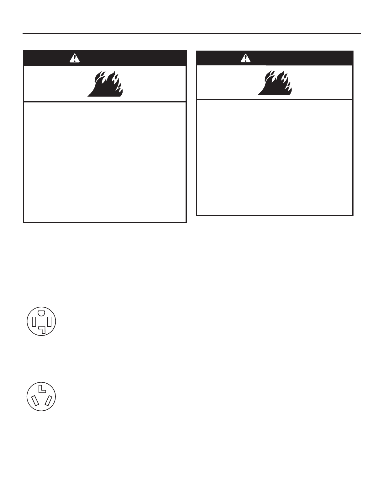
If your outlet looks like this:
Choose a 4-wire power supply cord with ring or
spade terminals and UL Listed strain relief. The
4-wire power supply cord, at least 4 ft. (1.22 m)
long, must have four 10 gauge copper wires and
match a 4-wire receptacle of NEMA Type 14-30R.
The ground wire (ground conductor) may be either
4-wire
receptacle
(14-30R)
green or bare. The neutral conductor must be
identified by a white cover.
If your outlet looks like this:
Choose a 3-wire power supply cord with ring
or spade terminals and UL Listed strain relief. The
3-wire power supply cord, at least 4 ft. (1.22 m)
long, must have three 10 gauge copper wires and
match a 3-wire receptacle of NEMA Type 10-30R.
3-wire
receptacle
(10-30R)
11
Loading...