


DE Ergänzende Betriebsanleitung
GB Supplementary operating instructions ES Manual de instrucciones complementario FR Mode d'emploi complémentaire
IT Istruzioni per l'uso integrative PT Manual complementar
NL Aanvullende gebruiksaanwijzing SV Tilläggsbruksanvisning
DK Supplerende betjeningsvejledning FI Täydentävä käyttöopas
GR Συμπληρωματικές οδηγίες λειτουργίας TR Tamamlayıcı kullanım kılavuzu
CZ Dodatečný návod k provozu PL Uzupełniająca instrukcja obsługi HU Kiegészítő üzemeltetési utasítás SK Doplnkový návod na obsluhu
SL Dodatna navodila za uporabo
EE Lisakasutusjuhend
LV Papildu lietošanas pamācība
LT Eksploatacijos instrukcijos papildymas
BG Допълнително Ръководство за работа
RO Manualul de utilizare suplimentar HR Dodatne Upute za uporabu
CN
JP
WT 2M

DE GB ES FR IT PT NL SV DK FI GR TR CZ PL HU SK SL EE
LT
LV
BG
RO
HR
CN
JP
Deutsch |
Menü | Zurücksetzen auf Werkseinstellungen | Werkzeugerkennung und Überlastbegrenzung | |
3 |
|
Potentialausgleich | Löten und Entlöten | Fehlermeldungen und Fehlerbehebung |
|||
|
|
||
English |
Menu | Resetting to factory settings | Tool recognition and overload limiting | |
11 |
|
Equipotential bonding | Soldering and desoldering | Error messages and error clearance |
|||
|
|
||
Español |
Menú | Restaurar la configuración de fábrica |Detección de la herramienta y limitación de sobrecarga| |
19 |
|
|
Equipotencial |Soldar y desoldar |Mensajes de error y su reparación |
|
|
Français |
Menu | Réinitialisation aux réglages d‘usine |Détection d‘outil et limite de surcharge| |
27 |
|
Compensation de potentiel | Soudage et dessoudage | Messages d‘erreur et élimination des défauts |
|||
Italiano |
Menu | Ripristino impostazioni di fabbrica | Codice utensile e limitazione di sovraccarico | |
35 |
|
Compensazione di potenziale | Saldare e dissaldare | Messaggi d‘errore e problemi |
|||
|
|
||
Portugues |
Menu | Reposição dos ajustes de fábrica | Reconhecimento de ferramenta e limitação de sobre- |
43 |
|
|
carga | Equilíbrio do potencial | Soldar e dessoldar | Avisos de erro e eliminação de falhas |
|
|
Nederlands |
Menu | Resetten naar fabrieksinstellingen |Gereedschapsherkenning en overbelastingsbegrenzing |
51 |
|
| Potentiaalvereffening | Solderen en soldeerruimen | Foutmeldingen en verhelpen van fouten |
|||
Svenska |
Meny | Återställa till fabriksinställningarna | Verktygsidentifiering och överbelastningsbegränsning |
59 |
|
|
| Potentialutjämning | Lödning och avlödning | Felmeddelanden och åtgärder |
|
|
Dansk |
Menu | Nulstilling til fabriksindstillinger | Værktøjsgenkendelse og overbelastningsbegrænsning | |
67 |
|
Spændingsudligning | Lodning og aflodning | Fejlmeldinger og fejlafhjælpning |
|||
|
|
||
Suomi |
Valikko | Palauttaminen tehdasasetuksiin |Työkalun tunnistus ja ylikuormitusrajoitus | |
75 |
|
Potentiaalin tasaus | Juottaminen ja juotoksen irrottaminen | Vikailmoitukset ja vikojen korjaaminen |
|||
Ελληνικα |
Μενού | Επαναφορά στις ρυθμίσεις του εργοστασίου |Αναγνώριση εργαλείων και περιορισμός |
83 |
|
υπερφόρτωσης |Εξίσωση δυναμικού|Συγκόλληση και αποκόλληση|Μηνύματα και άρση σφαλμάτων |
|||
Türkçe |
Menü | Fabrika ayarlarına geri alma | Alet tanıma ve aşırı yük sınırlaması | |
91 |
|
Potansiyel dengelemesi | Lehimleme ve lehim çıkartma | Hata mesajları ve hata giderme |
|||
|
|
||
Český |
Menu | Nastavení na výchozí hodnoty | Detekce nástroje a limit přetížení | Vyrovnání potenciálů | |
99 |
|
|
Pájení a odpájení | Chybová hlášení a odstraňování chyb |
|
|
Polski |
Menu | Resetowanie do nastawy fabrycznej | Wykrywanie narzędzia i ograniczanie przeciążenia | |
107 |
|
Wyrównanie potencjału | Lutowanie i wylutowywanie | Komunikaty o błędach i usuwanie błędów |
|||
Magyar |
Menü | Visszaállítás a gyári beállításokra | Eszközfelismerés és túlterhelési határ | |
115 |
|
Feszültségkiegyenlítő hüvely | Forrasztás és kiforrasztás | Hibaüzenetek és hibaelhárítás |
|||
|
|
||
Slovensky |
Ponuka | Obnovenie výrobných nastavení |Rozpoznanie nástroja a obmedzenie preťaženia| Zásuv- |
123 |
|
ka vyrovnania potenciálov| Spájkovanie a odspájkovanie | Chybové hlásenia a odstraňovanie chýb |
|||
Slovenščina |
Meni | Ponastavitev na tovarniške nastavitve |Prepoznavanje orodja in omejitev preobremenitve |Vtičnica |
131 |
|
za izenačevanje potenciala|Spajkanje in odspajkanje |Sporočila o napakah in odpravljanje napak |
|||
Eesti |
Menüü | Tehaseseadete taastamine | Instrumendituvastus ja ülekoormuse piirang | |
139 |
|
Potentsiaalide ühtlustuspuks | Jootmine ja lahtijootmine | Veateated ja vigade kõrvaldamine |
|||
|
|
||
Latviski |
Izvēlne | Atiestatīšana uz rūpnīcas iestatījumiem | Instrumentu atpazīšana un pārslodzes |
147 |
|
ierobežojums | Potenciālu izlīdzināšanas pieslēgvieta | Lodēšana un izlodēšana | |
|||
|
Paziņojumi par traucējumiem un traucējumu novēršana |
|
|
Lietuviškai |
Meniu | Gamyklinių nustatymų atstata | Įrankio atpažinimas ir perkrovos ribojimas | |
155 |
|
Potencialo išlyginimo įvorė | Litavimas ir išlitavimas | Pranešimai apie gedimus ir jų šalinimas |
|||
Български |
Меню | Возвращение к заводским установкам | Разпознаване инструмент и ограничение на |
163 |
|
претоварването | Изравняване на потенциалите | Спояване и разпояване | |
|||
|
Съобщения за неизправности и отстраняване |
|
|
Român |
Meniul | Resetare fabrică | Identificarea sculei şi limitarea suprasarcinii | Egalizare de potențial | |
171 |
|
|
Lipirea cu aliaj şi dezlipirea | Mesaje de defecțiune și remedierea defecțiunilor |
|
|
Hrvatski |
Izbornik | Vraćanje na tvorničke postavke | Prepoznavanje alata i ograničenje preopterećenja | |
179 |
|
Izjednačavanje potencijala | Lemljenje i odlemljivanje | |
|||
|
Dojave o nepravilnostima i uklanjanje nepravilnosti |
|
|
|
| | | | | |
187 |
|
|
| | | | | |
195 |
|
|
|
|

DEUTSCH DE
Menü 1
Wählen Sie den gewünschten Kanal aus.
Durch Betätigen der Menütaste gelangen Sie in das Menü 1
Durch Betätigen der Menütaste gelangen Sie in das Menü des zuvor ausgewählten Kanals.
Achten Sie bei Einstellungen im Menü immer darauf, welcher Kanal zuvor ausgewählt wurde. Der zuvor ausgewählte Kanal wird Ihnen im Display anzeigt.
Wird kein Kanal angezeigt beziehen sich die Änderungen auf das ganze Gerät.
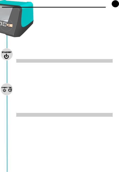
Standby Temperatur
Die Standby Temperatur ist ein voreinstellbarer Wert auf den ein Lötwerkzeug bei Nichtbenutzung geregelt wird.
Option |
|
Beschreibung |
OFF |
|
Standby deaktiviert (Werkseinstellung 180°C (360°F) |
100-300 |
°C |
Standby Temperatur, individuell einstellbar |
200-600 |
°F |
|
Standby Zeit (Temperaturabschaltung)
Bei Lötwerkzeugen mit Nutzungssensor im Griff, wird das Lötwerkzeug bei Nichtbenutzung nach der voreingestellten Standby Zeit auf die Standby Temperatur geregelt. Der im Werkzeug integrierte Sensor erkennt die Zustandsänderung und deaktiviert den Standby Zustand, sobald das Werkzeug bewegt wird.
Bei Lötwerkzeugen ohne Nutzungssensor, wird das Lötwerkzeug wenn nicht gelötet wird nach der voreingestellten Standby Zeit auf die Standby Temperatur geregelt.
Drücken der UP und DOWN Taste beendet den Standby Zustand. (Ausgenommen WMRP, WMRT, diese werden über einen Magnetkontakt geregelt.)
Option |
Beschreibung |
OFF |
Standby deaktiviert (Werkseinstellung 2 min) |
1-99 min |
Standby Zeit, individuell einstellbar |
3

DEUTSCH DE
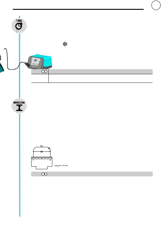
OFF Zeit
Bei Nichtgebrauch des Lötwerkzeugs wird nachAblauf der OFF Zeit die Heizung des Lötwerkzeuges deaktiviert. Die Temperaturabschaltung wird unabhängig von der eingestellten Standby-Funktion ausgeführt. Die Isttemperatur wird blinkend angezeigt und dient als Restwärmeanzeige. Im Display erscheint „AUTO-OFF“.
Solange das Lötwerkzeug abkühlt, wird in der 1-Kanal-Anzeige die Restwärme angezeigt. Zusätzlich blinkt „Cooling“ im Display. 


Bei der 2-Kanal-Anzeige blinkt °C / °F im Display des entsprechenden Kanals.
Sobald die Temperatur 50°C (122°F) unterschreitet, zeigt das Display OFF an und die Hintergrundbeleuchtung wird deaktiviert.
 Gleichzeitiges Drücken der UP und DOWN Taste beendet den OFF Zustand.
Option 1 2 Beschreibung
OFF |
OFF Zeit deaktiviert (Werkseinstellung 10 min) |
1-999 min |
OFF Zeit, individuell einstellbar |
Window-Funktion
Option 1 (Werkseinstellung):
Potentialfreier Schaltausgang auf ES FE stellen.
Einschränkung des Einstellbereichs auf ± 1-99 °C (±1-180 °F) ausgehend von einer durch die „LOCK“ Funktion verriegelten Temperatur.
Die verriegelte Temperatur stellt somit die Mitte des einstellbaren Temperaturfensters dar.
Option 2:
Potentialfreier Schaltausgang auf ES rob; ES FE / rob; ES rob / rob stellen.
Ausgehend von einer eingestellten, verriegelten Temperatur kann mit Hilfe der WINDOW-Funktion ein Temperaturfenster von ± 1-99 °C (±1-180 °F) eingestellt werden. Liegt die Ist-Temperatur innerhalb dieses Fensters, wird der potentialfreie Kontakt (Optokopplerausgang) durchgeschaltet.
Option 1 2 |
Beschreibung |
OFF |
Window-Funktion deaktiviert (Werkseinstellung OFF) |
1-99 °C |
Window-Funktion, individuell einstellbar |
1-180 °F |
|
4
DEUTSCH DE
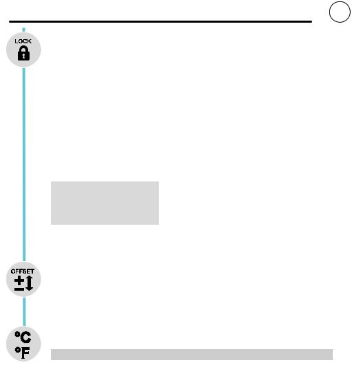
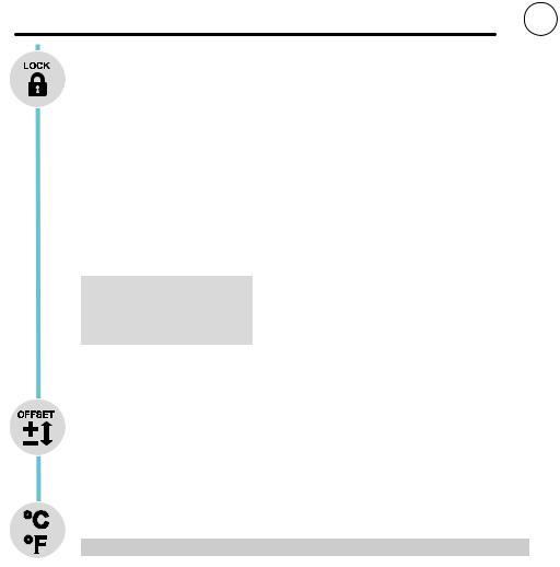
LOCK
Verriegelung der Station. Nach dem Verriegeln sind am Gerät keine Einstellungsänderungen mehr möglich.
Ausnahme 1: Festtemperaturtasten aktiviert. Ausnahme 2: Window-Funktion Option 1.
Alle anderen Einstellungen können bis zur Entriegelung nicht mehr verstellt werden.
Station verriegeln
Den gewünschten dreistelligen Verriegelungscode (zwischen 001-999) einstellen und mit der Menütaste bestätigen.
Die Verriegelung ist aktiv (im Display ist ein Schloss zu sehen)
Station entriegeln
Menütaste drücken. Im Display erscheint ON Den dreistelligen Verriegelungscode einstellen. Code mit der Menütaste bestätigen.
Code vergessen?
Wenden Sie sich bitte an unseren Kunden Service: technical-ser- vice@weller-tools.com
Offset
Die tatsächliche Lötspitzentemperatur kann durch Eingabe eines Temperatur-Offsets um ± 40 °C (± 72 °F) angepasst werden.
°C °F
Umschalten der Temperatureinheit.
Option |
Beschreibung |
°C |
Celsius |
°F |
Fahrenheit |
5

1
2
3
4
5
DEUTSCH DE
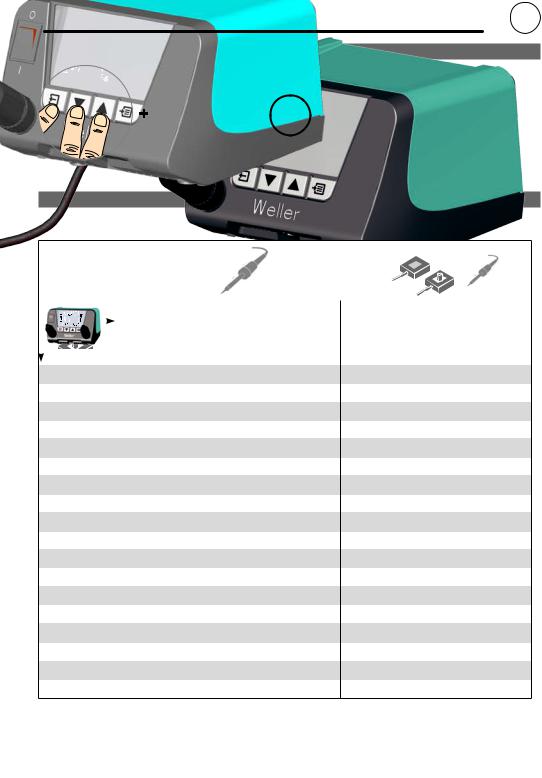
Menü 2
Wählen Sie den gewünschten Kanal aus.
Durch langes Betätigen (3 sec) der Menütaste gelangen Sie in das Menü 2 des gewünschten Kanals.
Achten Sie bei Einstellungen im Menü immer darauf, welcher Kanal zuvor ausgewählt wurde. Der zuvor ausgewählte Kanal wird Ihnen im Display anzeigt.
Wird kein Kanal angezeigt beziehen sich die Änderungen auf das ganze Gerät.
Festtemperaturen
Aktivierung der 2 individuell einstellbaren Festtemperaturen.
Option 1 2 |
Beschreibung |
ON |
Festtemperaturen aktiviert |
OFF |
Festtemperaturen deaktiviert (Werkseinstellung) |
Sind die Festtemperaturen aktiviert können diese über die UP und DOWN Tasten ausgewählt und verändert werden.
Hintergrundbeleuchtung
Option Beschreibung
0-100% LCD-Helligkeit (Werkseinstellung 80%)
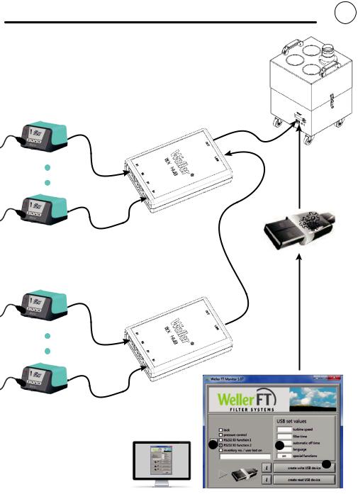
Potentialfreier Schaltausgang
Anwahl von Zero SmogAusgang oder Roboterausgang
Option 1 2 Beschreibung
ES FE |
Zero SmogAusgang aktiviert (Werkseinstellung) |
ES rob |
Roboterausgang aktiviert |
Empfindlichkeit
Option Beschreibung
1Unempfindlich – reagiert auf starke (lange) Bewegung
2
3Standard (Werkseinstellung)
4
5Empfindlich - reagiert auf leichte (kurze) Bewegung
6
DEUTSCH DE
Beispiel
Konfiguration ZeroSmog Ausgang
2 |
1 |
3
7

DEUTSCH DE
Zurücksetzen auf Werkseinstellungen
3  sec
sec
Beim Einschalten: Exit, UP und DOWN 3 Sekunden drücken
Werkzeugerkennung und Überlastbegrenzung
Die WT 2M verfügt über eine automatische Werkzeugerkennung die dem jeweilig angeschlossenen Werkzeug die entsprechenden Regelparameter zuordnet. Um eine Überlastung einer Station zu vermeiden, werden nur kompatible Werkzeuge unterstützt:
|
|
|
|
|
|
|
<![if ! IE]> <![endif]>WTA 50 |
<![if ! IE]> <![endif]>WP 80 |
<![if ! IE]> <![endif]>WSP 80 |
<![if ! IE]> <![endif]>MPR 80 |
<![if ! IE]> <![endif]>WSP 150 |
|
<![if ! IE]> <![endif]>WP 65 |
<![if ! IE]> <![endif]>WP 120 |
<![if ! IE]> <![endif]>WP 200 |
|
LR 21 |
<![if ! IE]> <![endif]>LR 21 |
<![if ! IE]> <![endif]>WMP |
||||||||||||
|
|||||||||||||||
|
. |
. |
. |
. |
. |
' |
. |
. |
|
' |
|||||
|
WTA 50 |
. |
. |
. |
. |
. |
' |
. |
. |
|
' |
||||
|
WP 80 |
. |
. |
|
|
|
' |
. |
. |
|
' |
||||
|
WSP 80 |
. |
. |
|
|
|
' |
. |
. |
|
' |
||||
|
MPR 80 |
. |
. |
|
|
|
' |
. |
. |
|
' |
||||
|
WSP 150 |
' |
' |
' |
' |
' |
' |
' |
' |
' |
' |
||||
|
WMP |
. |
. |
. |
. |
. |
' |
. |
. |
|
' |
||||
|
WP 65 |
. |
. |
. |
. |
. |
' |
. |
. |
|
' |
||||
|
WP 120 |
|
|
|
|
|
|
' |
|
|
|
' |
|||
|
WP 200 |
' |
' |
' |
' |
' |
' |
' |
' |
' |
' |
||||
|
WTP 90 |
. |
. |
|
|
|
' |
|
|
|
' |
||||
|
FE 75 |
. |
. |
|
|
|
' |
. |
. |
|
' |
||||
|
WHP 80 |
. |
. |
|
|
|
' |
. |
. |
|
' |
||||
|
WSB80 |
. |
. |
|
|
. |
' |
. |
. |
|
' |
||||
|
WSB 150 |
' |
' |
' |
' |
' |
' |
' |
' |
' |
' |
||||
|
WMRP |
. |
. |
. |
. |
. |
' |
. |
. |
|
' |
||||
|
WMRT |
. |
. |
|
|
|
' |
. |
. |
|
' |
||||
|
NO TOOL |
. |
. |
. |
. |
. |
. |
. |
. |
. |
|
||||
|
|
|
|
|
|
|
|
|
|
|
|
|
|
|
|
| <![if ! IE]> <![endif]>WTP 90 |
|
<![if ! IE]> <![endif]>FE 75 |
<![if ! IE]> <![endif]>WHP 80 |
|
<![if ! IE]> <![endif]>WSB80 |
|
<![if ! IE]> <![endif]>WSB 150 |
<![if ! IE]> <![endif]>WMRP |
|
<![if ! IE]> <![endif]>WMRT |
<![if ! IE]> <![endif]>NO TOOL |
|
|
|
|
||||||||
. |
|
. |
. |
|
. |
|
' |
. |
|
. |
. |
. |
|
. |
. |
|
. |
|
' |
. |
|
. |
. |
|
|
|
|
|
|
|
' |
. |
|
|
. |
|
|
|
|
|
|
|
' |
. |
|
|
. |
|
|
|
|
|
|
|
' |
. |
|
|
. |
' |
|
' |
' |
|
' |
|
' |
' |
|
' |
. |
. |
|
. |
. |
|
. |
|
' |
. |
|
. |
. |
. |
|
. |
. |
|
. |
|
' |
. |
|
. |
. |
|
|
|
|
|
|
|
' |
|
|
|
. |
' |
|
' |
' |
|
' |
|
' |
' |
|
' |
|
|
|
|
|
|
|
|
' |
. |
|
|
. |
|
|
|
|
|
|
|
' |
. |
|
|
. |
|
|
|
|
|
|
|
' |
. |
|
|
. |
|
|
|
|
|
|
|
' |
. |
|
|
. |
' |
|
' |
' |
|
' |
|
' |
' |
|
' |
. |
. |
|
. |
. |
|
. |
|
' |
. |
|
. |
. |
|
|
|
|
|
|
|
' |
. |
|
' |
. |
. |
|
. |
. |
|
. |
|
. |
. |
|
. |
. |
|
|
|
|
|
|
|
|
|
|
|
|
. Uneingeschränkte Funktion |
Leistungsreduzierung auf 150 W |
' Werkzeugkombination nicht möglich |
8

DEUTSCH DE
Potentialausgleich
a
b
c
d
Durch unterschiedliche Schaltung der 3,5 mm Schaltklinkenbuchse sind 4 Varianten möglich:
a |
Hart geerdet |
Ohne Stecker (Auslieferungszustand). |
|
|
|
b |
Potentialausgleich |
Mit Stecker,Ausgleichsleitung am Mittelkontakt. |
|
|
|
c |
Potentialfrei |
Mit Stecker |
|
|
|
d |
Weich geerdet |
Mit Stecker und eingelötetem Widerstand. Erdung |
|
|
über den gewählten Widerstand |
Löten und Entlöten
Führen Sie die Lötarbeiten gemäß der Betriebsanleitung Ihres angeschlossenen Lötwerkzeuges durch.
Behandlung der Lötspitzen
•Benetzen Sie beim erstenAufheizen die selektive und verzinnbare Lötspitze mit Lot. Dies entfernt lagerbedingte Oxydschichten und Unreinheiten der Lötspitze.
•Achten Sie bei Lötpausen und vor demAblegen des Lötkolbens darauf, dass die Lötspitze gut verzinnt ist.
•Verwenden Sie keine zu aggressiven Flussmittel.
•Achten Sie immer auf den ordnungsgemäßen Sitz der Lötspitzen.
•Wählen Sie dieArbeitstemperatur so niedrig wie möglich.
•Wählen Sie die für dieAnwendung größtmögliche Lötspitzenform
Daumenregel: ca. so groß wie das Lötpad.
•Sorgen Sie für einen großflächigen Wärmeübergang zwischen Lötspitze und Lötstelle, indem Sie die Lötspitze gut verzinnen.
•Schalten Sie bei längerenArbeitspausen das Lötsystem aus oder verwenden Sie die Weller Funktion zur Temperaturabsenkung bei Nichtgebrauch.
•Benetzen Sie die Spitze mit Lot, bevor Sie den Lötkolben für längere Zeit ablegen.
•Geben Sie das Lot direkt auf die Lötstelle, nicht auf die Lötspitze.
•Wechseln Sie die Lötspitzen mit dem dazugehörigen Werkzeug.
•Üben Sie keine mechanische Kraft auf die Lötspitze aus.
Hinweis
Die Steuergeräte wurden für eine mittlere Lötspitzengröße justiert. Abweichungen durch Spitzenwechsel oder der Verwendung von anderen Spitzenformen können entstehen.
9

|
|
|
|
|
|
|
DEUTSCH |
DE |
|
|
|
|
|
|
|||
Fehlermeldungen und Fehlerbehebung |
|
|
|
|
||||
Meldung/Symptom |
|
Mogliche Ursache |
|
Maßnahmen zur Abhilfe |
|
|||
|
|
|
||||||
|
|
|
|
|
|
|
|
|
• |
Anzeige „- - -“ |
|
• |
Werkzeug wurde nicht erkannt |
|
• |
Anschluss des Werkzeugs am Gerat |
|
|
|
|
• |
Werkzeug defekt |
|
|
uberprufen |
|
|
|
|
• |
Werkzeug nicht kompatibel |
|
• |
Angeschlossenes Werkzeug uberprufen |
|
• |
Keine Displayfunktion |
|
• |
Keine Netzspannung vorhanden |
|
• |
Netzschalter einschalten |
|
|
(Display aus) |
|
|
|
|
• |
Netzspannung uberprufen |
|
|
|
|
|
|
|
• |
Geratesicherung uberprufen |
|
• |
OFF |
|
• |
Station befindet sich im Standby oder |
|
• |
Mit den Tasten UP oder Down Lötwerk- |
|
|
|
|
|
OFF Modus |
|
|
zeug wieder aktivieren |
|
• |
Werkzeug bleibt kalt |
|
• |
Station befindet sich im Standby oder |
|
• |
Kolben bewegen |
|
|
|
|
|
OFF Modus |
|
• |
Mit den Tasten UP oder Down Lötwerk- |
|
|
|
|
|
|
|
|
zeug wieder aktivieren |
|
• |
Temperaturanzeige im |
|
• |
Heizung defekt |
|
• |
Lötwerkzeug prüfen / ersetzen |
|
|
Display |
|
|
|
|
|
|
|
• |
Werkzeug bleibt kalt |
|
|
|
|
|
|
|
• |
Station funktioniert nicht wie |
|
• |
Parameter verstellt |
|
• |
Station Zurücksetzen auf Werkseinstellun- |
|
|
gewohnt |
|
|
|
|
|
gen |
|
• |
Einstellungsänderungen nicht |
|
• |
Station verriegelt |
|
• |
Station entriegeln |
|
|
möglich |
|
|
|
|
|
|
|
• |
Zero Smog läuft nicht an |
|
• |
Keine Netzspannung vorhanden |
|
• |
Netzversorgung prüfen |
|
|
|
|
• |
Kein Signal vorhanden |
|
• |
Schnittstellenverkabelung prüfen |
|
|
|
|
|
|
|
• |
Einstellungen Schnittstelle prüfen |
|
10
ENGLISH EN
Menu 1
First choose the channel you wish to setup. Pressing the Menu button takes you to menu 1
Pressing the Menu button will take you into the menu of the previous selected channel.
Always make sure that the channel you have selected is the wished channel. The previously selected channel is shown on the display.
If no channel is displayed, the changes refer to the entire device.
Standby Temp.
The standby temperature is a preset value to which a soldering tool is adjusted when not in use.
Option |
|
Description |
OFF |
|
Standby deactivated (factory setting 180°C (360°F) |
100-300 |
°C |
Standby Temp., Individually adjustable |
200-600 |
°F |
|
Standby time (temperature deactivation)
On soldering tools with a usage sensor in the handle, the soldering tool is adjusted to the standby temperature after the preset standby time if not in use. The sensor integrated in the tool detects changes in status and deactivates standby mode as soon as the tool is moved.
On soldering tools without a usage sensor, the soldering tool is adjusted to the standby temperature after the preset standby time if no soldering process is being performed.
Pressing the UP and DOWN buttons exits standby mode.
(Not available for: WMRP, WMRT, which are controlled via a magnetic contact)
Option |
Description |
OFF |
Standby deactivated (factory setting 2 min) |
1-99 min |
Standby Time, Individually adjustable |
11
ENGLISH EN
OFF time
If the soldering tool is not in use, the heating for the soldering tool is deactivated after the OFF time elapses. Temperature deactivation is performed independently of the set standby function. The actual temperature is indicated by flashing LED and serves as a residual heat display. The display reads „OFF“.
As long as the soldering tool cools, the residual heat is displayed in the 1-channel display. Cooling also flashes in the display. 


For the 2-channel display, ° C / ° F flashes in the display of the corresponding channel.
As soon as the temperature falls below 50 °C (122 °F), OFF appears in the display and the backlighting is deactivated.
 Pressing the UP and DOWN buttons at the same time exits OFF mode.
Option 1 2 Description
OFF |
OFF time Deactivated (factory setting 10 min) |
1-999 min |
OFF time, Individually adjustable |
Window function
Option 1 (factory setting):
Set the potential-free switching output to ES FE.
Limiting the adjustment range to ± 1-99 °C (±1-180 °F) based on a temperature locked using the „LOCK“ function.
The locked temperature therefore represents the middle of the adjustable temperature window.
Option 2:
Set the potential-free switching output to ES rob; ES FE / rob; ES rob / rob.
Starting from a set, locked temperature, it is possible to set a temperature window of ± 1-99 °C (±1- 180 °F) using the WINDOW function. If the actual temperature is within this window, the potential-free contact (optocoupler output) becomes conductive.
Option 1 2 |
Description |
OFF |
Window function Deactivated (factory setting OFF) |
1-99 °C |
Window function, Individually adjustable |
1-180 °F |
|
12

ENGLISH EN
LOCK
Lock for the station.After the station is locked, it is no longer possible to change any device settings. Exception 1: Fixed temperature buttons activated.
Exception 2: Window function Option 1.
All other settings are disabled until the station is unlocked again.
Locking the station
Set the three-digit locking code of your choice (between 001 and 999) and confirm by pressing the Menu button.
The lock is active (the display shows a lock symbol)
Unlocking the station
Press the Menu button. ON appears in the display Set the three-digit locking code.
Press the Menu button to confirm the code.
Forgotten code?
Please contact our Customer Service: technical-service@weller- tools.com
Offset
The actual soldering-tip temperature can be adapted by entering a temperature offset around ± 40 °C (± 72 °F).
°C °F
Changing over the temperature unit.
Option |
Description |
°C |
Celsius |
°F |
Fahrenheit |
13

1
2
3
4
5
ENGLISH EN
Menu 2
First choose the channel you wish to setup.
Pressing and holding the Menu button (three seconds) takes you to menu 2 of the wished channel.
Always make sure that the channel you have selected is the wished channel. The previously selected channel is shown on the display.
If no channel is displayed, the changes refer to the entire device.
Fixed temperatures
Activation of the two fixed temperatures which can be individually adjusted.
Option 1 2 |
Description |
ON |
Fixed temperaturesActivated |
OFF |
Fixed temperatures Deactivated (factory setting) |
If the fixed temperatures are activated, they can be selected and changed by pressing the UP and DOWN buttons.
Backlighting
Option Description
0-100% LCD-Brightness (factory setting 80%)
Floating switching output
Selection of Zero-Smog output or robot output
Option 1 2 Description
ES FE |
Zero-Smog output activated (factory setting) |
ES rob |
Robot output activated |
Sensitivity
Option Description
1Non-Sensitive – Reacts to heavy (long) movement
2
3Standard (factory setting)
4
5Sensitive - Reacts to light (short) movement
14

ENGLISH EN
Example
Zero-Smog output configuration
2 |
1 |
3
15
ENGLISH EN
Resetting to factory settings
3  sec
sec
When switching on: Press and hold Exit, UP and DOWN for three seconds
Tool recognition and overload limiting
The WT 2M has automatic tool recognition which assigns the relevant control parameters to the connected tool. To prevent overloading a station, only compatible tools are supported:
|
|
|
|
|
|
|
<![if ! IE]> <![endif]>WTA 50 |
<![if ! IE]> <![endif]>WP 80 |
<![if ! IE]> <![endif]>WSP 80 |
<![if ! IE]> <![endif]>MPR 80 |
<![if ! IE]> <![endif]>WSP 150 |
|
<![if ! IE]> <![endif]>WP 65 |
<![if ! IE]> <![endif]>WP 120 |
<![if ! IE]> <![endif]>WP 200 |
|
LR 21 |
<![if ! IE]> <![endif]>LR 21 |
<![if ! IE]> <![endif]>WMP |
||||||||||||
|
|||||||||||||||
|
. |
. |
. |
. |
. |
' |
. |
. |
|
' |
|||||
|
WTA 50 |
. |
. |
. |
. |
. |
' |
. |
. |
|
' |
||||
|
WP 80 |
. |
. |
|
|
|
' |
. |
. |
|
' |
||||
|
WSP 80 |
. |
. |
|
|
|
' |
. |
. |
|
' |
||||
|
MPR 80 |
. |
. |
|
|
|
' |
. |
. |
|
' |
||||
|
WSP 150 |
' |
' |
' |
' |
' |
' |
' |
' |
' |
' |
||||
|
WMP |
. |
. |
. |
. |
. |
' |
. |
. |
|
' |
||||
|
WP 65 |
. |
. |
. |
. |
. |
' |
. |
. |
|
' |
||||
|
WP 120 |
|
|
|
|
|
|
' |
|
|
|
' |
|||
|
WP 200 |
' |
' |
' |
' |
' |
' |
' |
' |
' |
' |
||||
|
WTP 90 |
. |
. |
|
|
|
' |
|
|
|
' |
||||
|
FE 75 |
. |
. |
|
|
|
' |
. |
. |
|
' |
||||
|
WHP 80 |
. |
. |
|
|
|
' |
. |
. |
|
' |
||||
|
WSB80 |
. |
. |
|
|
. |
' |
. |
. |
|
' |
||||
|
WSB 150 |
' |
' |
' |
' |
' |
' |
' |
' |
' |
' |
||||
|
WMRP |
. |
. |
. |
. |
. |
' |
. |
. |
|
' |
||||
|
WMRT |
. |
. |
|
|
|
' |
. |
. |
|
' |
||||
|
NO TOOL |
. |
. |
. |
. |
. |
. |
. |
. |
. |
|
||||
|
|
|
|
|
|
|
|
|
|
|
|
|
|
|
|
| <![if ! IE]> <![endif]>WTP 90 |
|
<![if ! IE]> <![endif]>FE 75 |
<![if ! IE]> <![endif]>WHP 80 |
|
<![if ! IE]> <![endif]>WSB80 |
|
<![if ! IE]> <![endif]>WSB 150 |
<![if ! IE]> <![endif]>WMRP |
|
<![if ! IE]> <![endif]>WMRT |
<![if ! IE]> <![endif]>NO TOOL |
|
|
|
|
||||||||
. |
|
. |
. |
|
. |
|
' |
. |
|
. |
. |
. |
|
. |
. |
|
. |
|
' |
. |
|
. |
. |
|
|
|
|
|
|
|
' |
. |
|
|
. |
|
|
|
|
|
|
|
' |
. |
|
|
. |
|
|
|
|
|
|
|
' |
. |
|
|
. |
' |
|
' |
' |
|
' |
|
' |
' |
|
' |
. |
. |
|
. |
. |
|
. |
|
' |
. |
|
. |
. |
. |
|
. |
. |
|
. |
|
' |
. |
|
. |
. |
|
|
|
|
|
|
|
' |
|
|
|
. |
' |
|
' |
' |
|
' |
|
' |
' |
|
' |
|
|
|
|
|
|
|
|
' |
. |
|
|
. |
|
|
|
|
|
|
|
' |
. |
|
|
. |
|
|
|
|
|
|
|
' |
. |
|
|
. |
|
|
|
|
|
|
|
' |
. |
|
|
. |
' |
|
' |
' |
|
' |
|
' |
' |
|
' |
. |
. |
|
. |
. |
|
. |
|
' |
. |
|
. |
. |
|
|
|
|
|
|
|
' |
. |
|
' |
. |
. |
|
. |
. |
|
. |
|
. |
. |
|
. |
. |
|
|
|
|
|
|
|
|
|
|
|
|
. Unlimited function |
Power reduction to 150 W |
' Tool combination not possible |
16

ENGLISH EN
Equipotential bonding
Four variants are possible by connecting the 3.5 mm jack socket differently:
a
b
c
d
a |
Hard-grounded |
supplied without plug. |
|
|
|
b |
Equipotential bonding |
with plug, equaliser at centre contact. |
|
|
|
c |
Floating |
with plug |
|
|
|
d |
Soft-grounded |
with plug and soldered resistor. Grounded through |
|
|
selected resistor. |
Soldering and desoldering
Carry out soldering work as directed in the operating instructions of your connected soldering tool.
Handling the soldering tips |
soldering area. |
•Coat the selective and tinnable soldering tip with solder when heating it up for the first time. This removes oxide coatings which have formed during storage and impurities from the soldering tip.
•Make sure that the soldering tip is well coated with solder during breaks between soldering work and prior to storage of the device.
•Do not use aggressive fluxing agents.
•Always make sure that the soldering tips are fitted properly.
•Select as low a working temperature as possible.
•Select the largest possible soldering tip shape for the application.
Rule of thumb: the soldering tip should be roughly as large as the soldering pad.
•Coat the soldering tip well with solder to ensure that there is efficient heat transfer between the soldering tip and the
•Prior to extended breaks between soldering work, switch off the soldering system or use the Weller function to reduce the temperature when the soldering equipment is not in use.
•Coat the tip with solder prior to storage if you do not intend to use the soldering iron for an extended period of time.
•Apply solder directly to the soldering area, not to the soldering tip.
•Change the soldering tips using the designated tool.
•Do not apply mechanical force to the soldering tip.
Notice
The control units have been adapted to hold a medium-sized soldering tip. Discrepancies may occur if the tip is changed or a different shaped tip is used.
17

|
|
|
|
|
|
|
ENGLISH |
EN |
|
|
|
|
|
|
|||
Error messages and error clearance |
|
|
|
|
||||
Message/symptom |
|
Possible cause |
|
Remedial measures |
|
|||
|
|
|
||||||
|
|
|
|
|
|
|
|
|
• |
Display: „- - - |
|
• |
Tool has not been detected |
|
• |
Check connection of tool to device |
|
|
|
|
• |
Tool defective |
|
• |
Check connected tool |
|
|
|
|
• |
Tool not compatible |
|
|
|
|
• |
No display function (display |
|
• |
No mains supply voltage |
|
• |
Turn on mains power switch |
|
|
OFF) |
|
|
|
|
• |
Check mains supply voltage |
|
|
|
|
|
|
|
• |
Check device fuse |
|
• |
OFF |
|
• |
Station is on standby or in OFF mode |
|
• |
Reactive the soldering tool using the UP |
|
|
|
|
|
|
|
|
or DOWN buttons |
|
• |
Tool remains cold |
|
• |
Station is on standby or in OFF mode |
|
• |
Move the gun |
|
|
|
|
|
|
|
• |
Reactive the soldering tool using the UP |
|
|
|
|
|
|
|
|
or DOWN buttons |
|
• |
Temperature shown in the |
|
• |
Heating defective |
|
• |
Check/replace the soldering tool |
|
|
display |
|
|
|
|
|
|
|
• |
Tool remains cold |
|
|
|
|
|
|
|
• |
Station is not operating as it |
|
• |
Parameters set incorrectly |
|
• |
Reset the station to the factory settings |
|
|
usually does |
|
|
|
|
|
|
|
• |
Settings cannot be changed |
|
• |
Station locked |
|
• |
Unlocking the station |
|
• |
Zero Smog is not running |
|
• |
No mains supply voltage |
|
• |
Check the mains power supply |
|
|
|
|
• |
No signal detected |
|
• |
Check the interface wiring |
|
|
|
|
|
|
|
• |
Check the interface settings |
|
18
ESPAÑOL ES
Menú 1
Seleccione el canal que desee.
Al pulsar en la tecla de menú, se accede al menú 1
Pulsando la tecla de menú se accede al menú del canal previamente seleccionado.
Cuando realice los ajustes en el menú, asegúrese siempre de qué canal se ha seleccionado previamente. En la pantalla se mostrará el canal seleccionado con anterioridad.
Si no se muestra ningún canal, los cambios se aplican a todo el dispositivo
Temp. standby
La temperatura Standby es un valor predeterminado en el cual se regula una herramienta de soldar cuando no se utiliza.
Opcional |
Descripción |
|
OFF |
|
Standby desactivado (configuración de fábrica 180°C (360°F) |
100-300 |
°C |
Temp. standby, ajuste individual |
200-600 |
°F |
|
Tiempo standby (desconexión de la temperatura)
Las herramientas de soldadura que llevan un sensor de uso en el mango se regulan a la temperatura Standby si no se utilizan durante el tiempo de espera predeterminado. El sensor integrado en la herramienta detecta el cambio de estado y desactiva el estado Standby tan pronto como se mueve la herramienta.
Las herramientas de soldadura que no llevan un sensor de uso se regulan a la temperatura Standby si no se ha soldado durante el tiempo de espera predeterminado.
Al pulsar las teclas UP y DOWN, se finaliza el estado Standby.
(excepto en WMRP, WMRT, que se controlan a través de un contacto magnético).
Opcional |
Descripción |
OFF |
Standby desactivado (configuración de fábrica 2 min) |
1-99 min |
Tiempo standby, ajuste individual |
19

ESPAÑOL ES
Tiempo de desconexión (tiempo OFF)
Cuando no se utiliza la herramienta de soldadura, se desactiva el calentador de esta una vez transcurrido el tiempo OFF. La desconexión de temperatura se realiza independientemente de la función standby ajustada. La temperatura real parpadea y sirve para indicar el calor residual. Mientras aparece en la pantalla „AUTO-OFF“.
Mientras se enfría la herramienta de soldadura, en la pantalla de un canal se indica el calor residual. Además, en la pantalla parpadea la palabra «Cooling». 


En la pantalla de dos canales parpadea «°C/°F» en la pantalla del canal correspondiente.
En cuanto la temperatura es inferior a 50 °C (122 °F), en la pantalla aparece «OFF» y se desactiva la iluminación de fondo.
 Al pulsar las teclas UP y DOWN de forma simultánea, se finaliza el estado OFF.
Opcional |
Descripción |
|
1 |
2 |
|
|
|
|
OFF |
Tiempo de desconexión (tiempo OFF) desactivado (configuración de fábrica 10 min) |
|
1-999 min |
Tiempo de desconexión (tiempo OFF), ajuste individual |
|
Función Window
Opcional 1 (configuración de fábrica):
Ajustar el circuito de salida sin potencial a «ES FE».
Limitación del rango de ajuste a ±1-99 °C (±1-180 °F) a partir de una temperatura bloqueada con la función «LOCK».
Por tanto la temperatura bloqueada representa el centro del rango térmico ajustable.
Opcional 2:
Ajustar el circuito de salida sin potencial a ES rob; ES FE/rob; ES rob/rob.
Partiendo de una temperatura ajustada y bloqueada es posible ajustar una ventana de temperatura de aproximadamente ±1-99 °C (±1-180 °F) con la ayuda de la función WINDOW. Si la temperatura real está dentro de este margen, el contacto sin potencial (salida del optoacoplador) estará conectado.
Opcional |
Descripción |
|
1 |
2 |
|
|
|
|
OFF |
Función Window desactivado (configuración de fábrica OFF) |
|
1-99 °C |
Función Window, ajuste individual |
|
1-180 °F |
|
|
20
ESPAÑOL ES
LOCK
Bloqueo de la estación. Cuando se bloquea el aparato, ya no se pueden cambiar los ajustes. Excepción 1: Teclas de temperatura fija activadas.
Excepción 2: Función Window Opcional 1.
No es posible cambiar ninguno de los demás ajustes hasta que se desbloquee.
Bloquear estación
Ajustar el código de bloqueo deseado con tres dígitos (comprendidos entre 001 y 999) y confirmar mediante la tecla del menú.
El bloqueo está activado (en la pantalla aparecerá un candado)
Desbloquear la estación
Pulsar la tecla de menú. En la pantalla, aparecerá «ON» Ajustar el código de bloqueo de tres dígitos.
Confirmar el código con la tecla de menú.
¿Ha olvidado el código?
Por favor, diríjase a nuestro servicio técnico: technical-service@ weller-tools.com
Offset
La temperatura real de la punta del soldador se puede ajustar introduciendo un offset de temperatura de aproximadamente ± 40 °C (± 72 °F).
°C °F
Cambiar la unidad de temperatura.
Opcional |
Descripción |
°C |
Grados centígrados |
°F |
Fahrenheit |
21

1
2
3
4
5
ESPAÑOL ES
Menú 2
Seleccione el canal que desee.
Al pulsar de forma prolongada (3 segundos) la tecla del menú, se accede al menú 2 del canal deseado.
Cuando realice los ajustes en el menú, asegúrese siempre de qué canal se ha seleccionado previamente. En la pantalla se mostrará el canal seleccionado con anterioridad.
Si no se muestra ningún canal, los cambios se aplican a todo el dispositivo
Temperaturas fijas
Activación de las 2 temperaturas fijas ajustables individualmente.
Opcional |
Descripción |
|
1 |
2 |
|
|
|
|
ON |
Temperaturas fijas activado |
|
OFF |
Temperaturas fijas desactivado (configuración de fábrica) |
|
Si las temperaturas fijas están activadas, se pueden seleccionar y cambiar mediante las teclas UP y DOWN.
Iluminación del fondo
Opcional Descripción
0-100% Brillo LCD (configuración de fábrica 80%)
Salida sin potencial
Seleccionar salida Zero Smog o la salida de robot
Opcional |
Descripción |
|
1 |
2 |
|
|
|
|
ES FE |
Salida Zero Smog activada (configuración de fábrica) |
|
ES rob |
Salida de robot activada |
|
Sensibilidad
Opcional Descripción
1Insensible – reacciona a movimientos fuertes (largos)
2
3Estándar (configuración de fábrica)
4
5Sensible - reacciona a movimiento suaves (cortos)
22

ESPAÑOL ES
Ejemplo
Configuración de salida Zero Smog
2 |
1 |
3
23

ESPAÑOL ES
Restaurar la configuración de fábrica
3  sec
sec
Al conectar: Pulsar durante 3 segundos Exit, UP y DOWN
Detección de la herramienta y limitación de sobrecarga
La WT 2M cuenta con una detección automática de la herramienta que asigna los parámetros de control adecuados a la correspondiente herramienta conectada. Para evitar una sobrecarga de la estación, solo soporta herramientas compatibles:
|
|
|
|
|
|
|
<![if ! IE]> <![endif]>WTA 50 |
<![if ! IE]> <![endif]>WP 80 |
<![if ! IE]> <![endif]>WSP 80 |
<![if ! IE]> <![endif]>MPR 80 |
<![if ! IE]> <![endif]>WSP 150 |
|
<![if ! IE]> <![endif]>WP 65 |
<![if ! IE]> <![endif]>WP 120 |
<![if ! IE]> <![endif]>WP 200 |
|
LR 21 |
<![if ! IE]> <![endif]>LR 21 |
<![if ! IE]> <![endif]>WMP |
||||||||||||
|
|||||||||||||||
|
. |
. |
. |
. |
. |
' |
. |
. |
|
' |
|||||
|
WTA 50 |
. |
. |
. |
. |
. |
' |
. |
. |
|
' |
||||
|
WP 80 |
. |
. |
|
|
|
' |
. |
. |
|
' |
||||
|
WSP 80 |
. |
. |
|
|
|
' |
. |
. |
|
' |
||||
|
MPR 80 |
. |
. |
|
|
|
' |
. |
. |
|
' |
||||
|
WSP 150 |
' |
' |
' |
' |
' |
' |
' |
' |
' |
' |
||||
|
WMP |
. |
. |
. |
. |
. |
' |
. |
. |
|
' |
||||
|
WP 65 |
. |
. |
. |
. |
. |
' |
. |
. |
|
' |
||||
|
WP 120 |
|
|
|
|
|
|
' |
|
|
|
' |
|||
|
WP 200 |
' |
' |
' |
' |
' |
' |
' |
' |
' |
' |
||||
|
WTP 90 |
. |
. |
|
|
|
' |
|
|
|
' |
||||
|
FE 75 |
. |
. |
|
|
|
' |
. |
. |
|
' |
||||
|
WHP 80 |
. |
. |
|
|
|
' |
. |
. |
|
' |
||||
|
WSB80 |
. |
. |
|
|
. |
' |
. |
. |
|
' |
||||
|
WSB 150 |
' |
' |
' |
' |
' |
' |
' |
' |
' |
' |
||||
|
WMRP |
. |
. |
. |
. |
. |
' |
. |
. |
|
' |
||||
|
WMRT |
. |
. |
|
|
|
' |
. |
. |
|
' |
||||
|
NO TOOL |
. |
. |
. |
. |
. |
. |
. |
. |
. |
|
||||
|
|
|
|
|
|
|
|
|
|
|
|
|
|
|
|
| <![if ! IE]> <![endif]>WTP 90 |
|
<![if ! IE]> <![endif]>FE 75 |
<![if ! IE]> <![endif]>WHP 80 |
|
<![if ! IE]> <![endif]>WSB80 |
|
<![if ! IE]> <![endif]>WSB 150 |
<![if ! IE]> <![endif]>WMRP |
|
<![if ! IE]> <![endif]>WMRT |
<![if ! IE]> <![endif]>NO TOOL |
|
|
|
|
||||||||
. |
|
. |
. |
|
. |
|
' |
. |
|
. |
. |
. |
|
. |
. |
|
. |
|
' |
. |
|
. |
. |
|
|
|
|
|
|
|
' |
. |
|
|
. |
|
|
|
|
|
|
|
' |
. |
|
|
. |
|
|
|
|
|
|
|
' |
. |
|
|
. |
' |
|
' |
' |
|
' |
|
' |
' |
|
' |
. |
. |
|
. |
. |
|
. |
|
' |
. |
|
. |
. |
. |
|
. |
. |
|
. |
|
' |
. |
|
. |
. |
|
|
|
|
|
|
|
' |
|
|
|
. |
' |
|
' |
' |
|
' |
|
' |
' |
|
' |
|
|
|
|
|
|
|
|
' |
. |
|
|
. |
|
|
|
|
|
|
|
' |
. |
|
|
. |
|
|
|
|
|
|
|
' |
. |
|
|
. |
|
|
|
|
|
|
|
' |
. |
|
|
. |
' |
|
' |
' |
|
' |
|
' |
' |
|
' |
. |
. |
|
. |
. |
|
. |
|
' |
. |
|
. |
. |
|
|
|
|
|
|
|
' |
. |
|
' |
. |
. |
|
. |
. |
|
. |
|
. |
. |
|
. |
. |
|
|
|
|
|
|
|
|
|
|
|
|
. Función ilimitada |
Reducción de potencia a 150 W |
' Combinación de herramientas no |
|
|
permitida |
24

ESPAÑOL ES
Equipotencial
a
b
c
d
Gracias a las diferentes posibilidades de conexión del conector hembra de 3,5 mm hay 4 variantes posibles:
a |
Toma de tierra directa |
sin conector (estado de suministro). |
|
|
|
b |
Equipotencial |
con conector, línea equipotencial en el contacto |
|
|
central. |
c |
Sin potencial |
con conector |
|
|
|
d |
Toma de tierra |
con enchufe y resistencia soldada. Puesta a tierra a |
|
indirecta |
través de la resistencia seleccionada |
Soldar y desoldar
Realice los trabajos de soldadura según el manual de uso de la herramienta conectada.
Manipulación de las puntas de soldar
•Aplicar un poco de estaño a la punta de soldar cuando la ponga en funcionamiento por primera vez. De esta forma podrá eliminar capas de óxido o impurezas en la punta de soldar que se hayan podido formar durante su almacenamiento.
•Cuando no vaya a usar el soldador o cuando lo coloque en el soporte asegurarse de que la punta esté bien estañada.
•No usar fundentes (pasta de soldar) agresivos.
•Asegurarse siempre de que la punta de soldar esté colocada correctamente.
•Ajustar la temperatura de trabajo más baja posible.
•Usar la punta de soldar de mayor tamaño posible para la aplicación deseada.
Regla general: aprox. tan grande como el punto de soldadura.
•Asegurarse de que la transmisión térmica desde la punta de soldar a la zona de soldar sea lo más grande posible
aplicando una buena capa de estaño a la punta de soldar.
•En fases de inactividad prolongadas desconectar el equipo soldador y usar la función Weller de reducción de temperatura en caso de inactividad.
•Aplicar estaño a la punta de soldar antes de guardar el soldador durante un espacio de tiempo prolongado.
•Aplicar el estaño directamente en el punto de soldadura, no en la punta de soldar.
•Cambiar las puntas de soltar con la herramienta correspondiente.
•No someter la punta de soldar a esfuerzos mecánicos.
Aviso
Las unidades de control están ajustadas para funcionar con puntas de soldar de tamaño mediano. Pueden surgir diferencias de comportamiento debido al cambio de punta o al utilizar puntas con una forma diferente.
25

|
|
|
|
|
ESPAÑOL |
ES |
|
|
|
|
|||
Mensajes de error y su reparacion |
|
|
|
|||
Mensaje/Síntoma |
Causa posible |
Reparacion |
|
|||
|
|
|
|
|
|
|
• |
Indicacion „- - -“ |
• |
No se ha detectado la herramienta |
• |
Comprobar la conexion de la herramienta |
|
|
|
• |
Herramienta defectuosa |
|
al aparato |
|
|
|
• |
Herramienta no compatible |
• |
Comprobar la herramienta conectada |
|
• |
Sin funcion de pantalla |
• |
No hay tension de red disponible |
• |
Conectar el interruptor principal |
|
|
(pantalla desconectada) |
|
|
• |
Comprobar la tension de red |
|
|
|
|
|
• |
Comprobar el fusible del aparato |
|
• |
OFF |
• |
La estación se encuentra en Standby o en |
• |
Activar de nuevo la herramienta de |
|
|
|
|
modo OFF |
|
soldadura con las teclas UP o Down |
|
• |
La herramienta se mantiene |
• |
La estación se encuentra en Standby o en |
• |
Mover los pistones |
|
|
fría |
|
modo OFF |
• |
Activar de nuevo la herramienta de |
|
|
|
|
|
|
soldadura con las teclas UP o Down |
|
• |
Indicación de temperatura en |
• |
Fallo en el calentador |
• |
Comprobar/sustituir la herramienta de |
|
|
la pantalla |
|
|
|
soldadura |
|
•La herramienta se mantiene fría
• |
La estación no funciona de la |
• |
Parámetros ajustados |
• |
Restablecer la estación a los ajustes de |
|
manera habitual |
|
|
|
fábrica |
• |
No se pueden cambiar los |
• |
Estación bloqueada |
• |
Desbloquear la estación |
|
ajustes |
|
|
|
|
• |
Zero Smog no arranca |
• |
No hay tension de red disponible |
• |
Comprobar la alimentación de red |
|
|
• |
No hay señal disponible |
• |
Comprobar el cableado de la interfaz |
|
|
|
|
• |
Comprobar los ajustes de la interfaz |
26

FRANÇAIS FR
Menu 1
Sélectionnez le canal souhaité.
Vous pouvez accéder au menu 1 en actionnant la touche de menu
Une pression sur la touche de menu vous permet d‘accéder au menu du canal sélectionné auparavant.
Lorsque vous effectuez des réglages dans le menu, assurez-vous toujours de savoir quel canal a été sélectionné précédemment. Le canal sélectionné précédemment s‘affiche sur l‘écran.
Si aucun canal ne s‘affiche, les changements se réfèrent à l‘ensemble de l‘appareil.
Temp. Stand-by
La température de veille est une valeur prédéterminable sur laquelle un outil de soudage est réglé en cas de non-utilisation.
Option |
|
Description |
OFF |
|
État de veille désactivé (réglage usine 180°C (360°F) |
100-300 |
°C |
Temp. Stand-by, réglable individuellement |
200-600 |
°F |
|
Durée de mise en veille (désactivation de la température)
Les outils de soudage dont la poignée est pourvue d’un capteur d’utilisation sont réglés sur la température de veille en cas de non-utilisation après écoulement du temps de veille prédéfini. Le capteur intégré dans l‘outil détecte le changement d‘état et désactive l‘état de veille sitôt que l‘outil est déplacé.
Les outils de soudage dépourvus de capteur d’utilisation sont réglés sur la température de veille en cas de non-utilisation après écoulement du temps de veille prédéfini.
Une pression sur les touches UP et DOWN permet d‘arrêter l’état de veille. (excepté WMRP, WMRT, ceux-ci sont régulés par un contact magnétique.)
Option |
Description |
OFF |
État de veille désactivé (réglage usine 2 min) |
1-99 min |
Temps Standby, réglable individuellement |
27

FRANÇAIS FR
Temps OFF
En cas de non-utilisation de l’outil de soudage, son chauffage est désactivé après écoulement du temps OFF. La désactivation de la température s‘effectue indépendamment de la fonction de veille réglée. La température réelle est affichée de façon clignotante et sert d‘affichage de chaleur résiduelle. „AUTO-OFF“ apparaît à l‘affichage.
La chaleur résiduelle est affichée dans l‘affichage 1 canal tant que l‘outil de soudage refroidit. En outre, l’affichage « Cooling » (« Refroidissement ») clignote sur l’écran. 


°C / °F clignote sur l‘écran du canal correspondant dans l‘affichage à 2 canaux.
Dès que la température descend au-dessous de 50 °C (122 °F), l’écran affiche OFF et le rétroéclairage est désactivé.
 Une pression simultanée des touches UP et DOWN permet d‘arrêter l’état OFF.
Option 1 2 Description
OFF |
Temps OFF désactivé (réglage usine 10 min) |
1-999 min |
Temps OFF, réglable individuellement |
Fonction Window Option 1 (réglage usine):
Régler la sortie de commutation libre de potentiel sur ES FE .
Limitation de la plage de réglage à ± 1-99 °C (±1-180 °F) en partant d’une température verrouillée grâce à la fonction « LOCK ».
La température verrouillée se situe ainsi au milieu de la fenêtre de température réglable.
Option 2:
Régler la sortie de commutation libre de potentiel sur ES rob; ES FE / rob; ES rob / rob.
En partant d‘une température réglée et verrouillée, la fonction WINDOW permet de régler une fenêtre de température de ± 1 -99 °C (±1 -180 °F). Si la température réelle se situe dans ladite fenêtre, le contact libre de potentiel (sortie sur opto-coupleur) est commuté.
Option 1 2 |
Description |
OFF |
Fonction Window désactivé (réglage usine OFF) |
1-99 °C |
Fonction Window, réglable individuellement |
1-180 °F |
|
28
FRANÇAIS FR
LOCK
Verrouillage de la station.Aucune modification de réglage n’est possible sur l’outil après verrouillage. Exception 1: Boutons de température fixe activés.
Exception 2: Fonction Window Option 1.
Tous les autres réglages ne peuvent plus être modifiés jusqu‘au déverrouillage.
Verrouiller la station
Régler le code de verrouillage à trois chiffres souhaité (entre 001-999) et le valider à l’aide de la touche de menu.
Le verrouillage est actif (un cadenas est visible à l‘affichage)
Déverrouiller la station
Appuyer sur la touche de menu. L‘affichage ON apparaît sur l‘écran Régler le code de verrouillage à trois chiffres.
Valider le code à l’aide de la touche de menu.
Code oublié ?
Veuillez vous adresser à notre service client : technical-service@ weller-tools.com
Offset
La température réelle de la panne à souder peut être adaptée en entrant un décalage de température (offset) de ± 40 °C (± 72 °F).
°C °F
Commutation de l‘unité de température.
Option |
Description |
°C |
Celsius |
°F |
Fahrenheit |
29

1
2
3
4
5
FRANÇAIS FR
Menu 2
Sélectionnez le canal souhaité.
Une pression prolongée (3 secondes) sur la touche de menu vous permet d‘accéder au menu 2 du canal souhaité.
Lorsque vous effectuez des réglages dans le menu, assurez-vous toujours de savoir quel canal a été sélectionné précédemment. Le canal sélectionné précédemment s‘affiche sur l‘écran.
Si aucun canal ne s‘affiche, les changements se réfèrent à l‘ensemble de l‘appareil.
Températures fixes
Activation des 2 températures fixes réglables individuellement.
Option 1 2 |
Description |
ON |
Températures fixes activé |
OFF |
Températures fixes désactivé (réglage usine) |
Lorsqu‘elles sont activées, les températures fixes peuvent être sélectionnées et modifiées à l‘aide des touches UP et DOWN.
Rétroéclairage
Option Description
0-100% Luminosité LCD (réglage usine 80%)
Sortie de commutation libre de potentiel
Sélection de la sortie Zero Smog ou sortie robot
Option 1 2 |
Description |
ES FE |
Sortie Zero Smog activée (réglage usine) |
ES rob |
Sortie robot activée |
Sensibilité
Option Description
1Insensible – réagit à un mouvement fort (long)
2
3Standard (réglage usine)
4
5Sensible - réagit à un mouvement léger (court)
30
 Loading...