

Weider PRO 4250 Owner's Manual
Model No. 831.15402.2
Serial No.
Write the serial number in the
space above for reference.
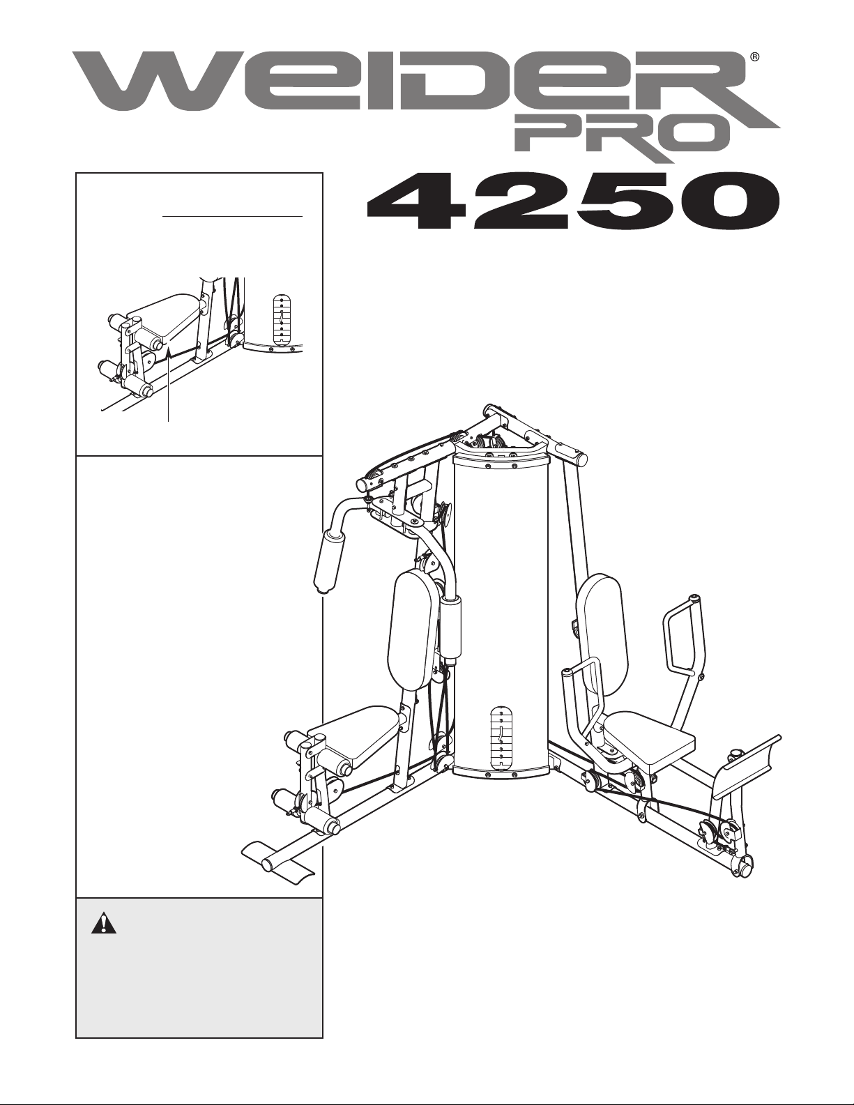
Serial Number Decal (under seat)
• Assembly
• Adjustments
• Troubleshooting
• Part List and Drawing
WEIGHT SYSTEM EXERCISER
User’s Manual
CAUTION
Read all precautions and instructions in this manual before using
this equipment. Save this manu
al for future reference.
Patent Pending
Sears, Roebuck and Co., Hoffman Estates, IL
60179
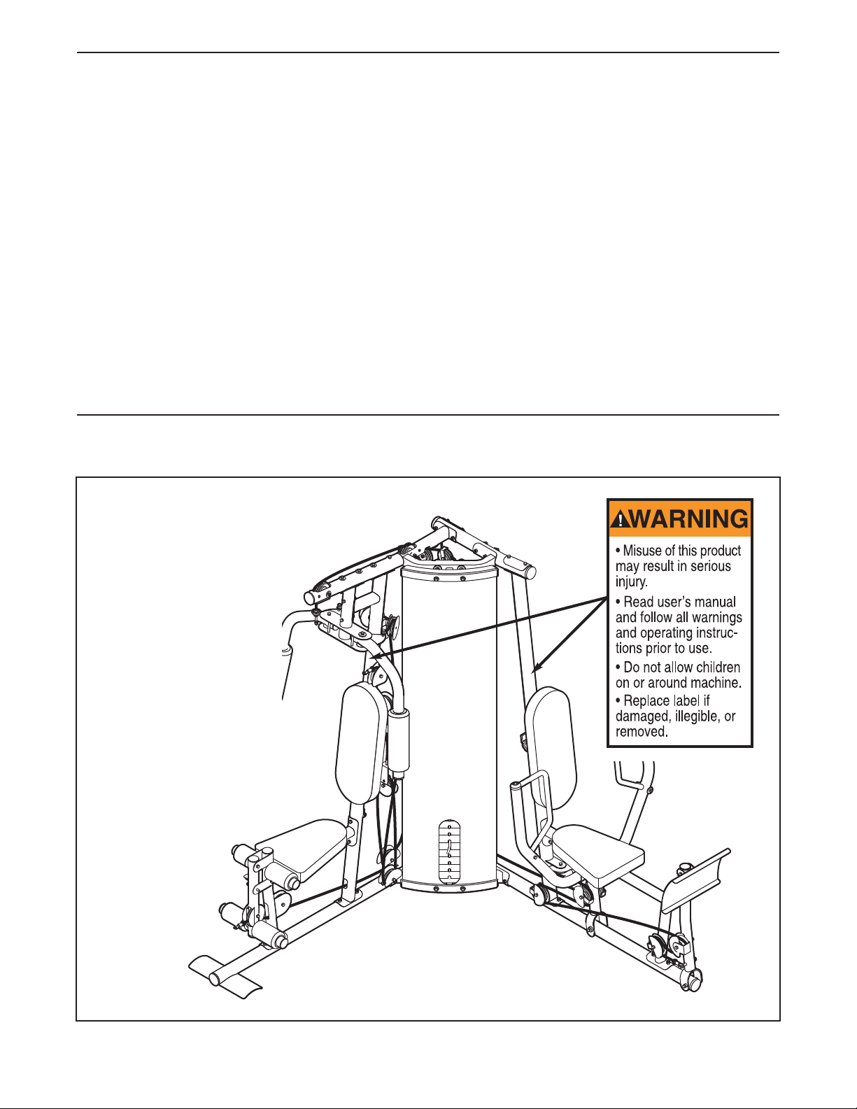
TABLE OF CONTENTS
WARNING DECAL PLACEMENT . . . . . . . . . . . . . . . . . . . . . . . . . . . . . . . . . . . . . . . . . . . . . . . . . . . . . . . . . . . . . 2
IMPORTANT PRECAUTIONS . . . . . . . . . . . . . . . . . . . . . . . . . . . . . . . . . . . . . . . . . . . . . . . . . . . . . . . . . . . . . . . . 3
EFORE YOU BEGIN . . . . . . . . . . . . . . . . . . . . . . . . . . . . . . . . . . . . . . . . . . . . . . . . . . . . . . . . . . . . . . . . . . . . . . 4
B
SSEMBLY . . . . . . . . . . . . . . . . . . . . . . . . . . . . . . . . . . . . . . . . . . . . . . . . . . . . . . . . . . . . . . . . . . . . . . . . . . . . . . 5
A
ADJUSTMENTS . . . . . . . . . . . . . . . . . . . . . . . . . . . . . . . . . . . . . . . . . . . . . . . . . . . . . . . . . . . . . . . . . . . . . . . . . . 23
WEIGHT RESISTANCE CHART . . . . . . . . . . . . . . . . . . . . . . . . . . . . . . . . . . . . . . . . . . . . . . . . . . . . . . . . . . . . . .25
CABLE DIAGRAMS . . . . . . . . . . . . . . . . . . . . . . . . . . . . . . . . . . . . . . . . . . . . . . . . . . . . . . . . . . . . . . . . . . . . . . .26
MAINTENANCE . . . . . . . . . . . . . . . . . . . . . . . . . . . . . . . . . . . . . . . . . . . . . . . . . . . . . . . . . . . . . . . . . . . . . . . . . .28
EXERCISE GUIDELINES . . . . . . . . . . . . . . . . . . . . . . . . . . . . . . . . . . . . . . . . . . . . . . . . . . . . . . . . . . . . . . . . . . 29
ORDERING REPLACEMENT PARTS . . . . . . . . . . . . . . . . . . . . . . . . . . . . . . . . . . . . . . . . . . . . . . . . . .Back Cover
FULL 90-DAY WARRANTY . . . . . . . . . . . . . . . . . . . . . . . . . . . . . . . . . . . . . . . . . . . . . . . . . . . . . . . . . . Back Cover
Note: A PART IDENTIFICATION CHART and a PART LIST/EXPLODED DRAWING are attached in the center of
this manual. Remove the PART IDENTIFICATION CHART and PART LIST/EXPLODED DRAWING before beginning assembly.
WARNING DECAL PLACEMENT
The decal shown here
has been placed on the
weight system. If the
decal is missing or illegible, please call toll-free
1-877-992-5999, Monday
through Friday, 6 a.m.
until 6 p.m. Mountain
Time, and order a free
replacement decal. Apply
the decal in the location
shown.
2

IMPORTANT PRECAUTIONS
WARNING: To reduce the risk of serious injury, read the following important precautions
before using the weight system.
1. Read all instructions in this manual and all
warnings on the weight system before using
the weight system. Use the weight system
only as described in this manual.
2. It is the responsibility of the owner to ensure
that all users of the weight system are adequately informed of all precautions.
3. The weight system is intended for home use
only. Do not use the weight system in any
commercial, rental, or institutional setting.
4. Keep the weight system indoors, away from
moisture and dust. Place the weight system
on a level surface, with a mat beneath it to
protect the floor or carpet. Make sure that
there is enough clearance around the weight
system to mount, dismount, and use the
weight system.
5. Inspect and properly tighten all parts regularly. Replace any worn parts immediately.
6. Keep children under 12 and pets away from
the weight system at all times.
7. Always wear athletic shoes for foot protection while exercising.
8. Keep hands and feet away from moving parts.
10. The weight system is designed to be used
only with the included weight. Do not use the
weight system with dumbbells or any other
type of weight to increase the resistance.
11. Make sure that the cables remain on the pulleys at all times. If the cables bind as you are
exercising, stop immediately and make sure
that the cables are on the pulleys. Replace all
cables at least every two years.
12. Always secure the weight stack with the lock
pin and lock after exercising to prevent
unauthorized use of the weight system (see
LOCKING THE WEIGHT STACK on page 24).
13. Always stand on the foot plate when performing an exercise that could cause the
weight system to tip.
14. Never release the arms, leg lever, lat bar, leg
press, ab strap, or handle while weights are
raised. The weights will fall with great force.
Always disconnect the lat bar from the
15.
weight system when performing an exercise
that does not use the lat bar.
16. If you feel pain or dizziness at any time while
exercising, stop immediately and begin cooling down.
The weight system is designed to support a
9.
maximum user weight of 300 pounds.
WARNING: Before beginning this or any exercise program, consult your physician. This
is especially important for persons over the age of 35 or persons with pre-existing health problems.
Read all instructions before using. Sears assumes no responsibility for personal injury or property
damage sustained by or through the use of this product.
3
BEFORE YOU BEGIN
hank you for selecting the versatile WEIDER
T
4250 weight system. The weight system offers an
impressive array of weight stations designed to develop every major muscle group of the body. Whether
our goal is to tone your body, build dramatic muscle
y
size and strength, or improve your cardiovascular system, the weight system will help you to achieve the
specific results you want.
For your benefit, read this manual carefully before
using the weight system. If you have questions after
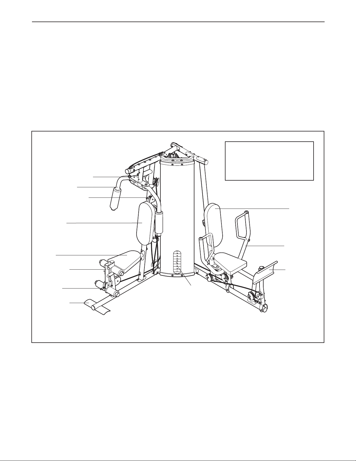
Right Side
High Pulley Station
Butterfly Arm
Ab Pulley Station
®
RO
P
eading this manual, call 1-800-4-MY-HOME
r
(1-800-469-4663). To help us assist you, please note
the product model number and serial number before
calling. The model number is 831.15402.2. The serial
umber can be found on a decal attached to the
n
weight system (see the front cover of this manual for
the location of the decal).
Before reading further, please review the drawing
below and familiarize yourself with the parts that are
labeled.
ASSEMBLED DIMENSIONS:
Height: 77 in. / 196 cm
Width: 81 in. / 206 cm
Depth: 59 in. / 150 cm
®
Backrest
Backrest
Seat
Leg Lever
Low Pulley
Station
Foot Plate
Note: The terms “right side” and “left side” are determined relative to a person sitting on a seat;
they do not correspond to right and left on the drawings in the manual.
Weight
Stack
Left Side
Press Arm
Leg Press
4

ASSEMBLY
Make Assembly Easier for Yourself
Everything in this manual is designed to
ensure that the weight system can be assembled successfully by anyone. Before begin-
ning assembly, make sure to read the
information on this page. This brief introduction will save you much more time than
it takes to read it.
Assembly Requires Two Persons
For your convenience and safety, assemble the
weight system with the help of another person.
Make sure you have the following tools:
• Two adjustable wrenches
• One standard screwdriver
• One phillips screwdriver
• One rubber mallet
• You will also need grease or petroleum jelly, a
small amount of soapy water, and clear tape or
masking tape.
Note: Assembly will be more convenient if you have
a socket set, a set of open-end or closed-end
wrenches, or a set of ratchet wrenches.
Set Aside Enough Time
Due to the many features of the weight system, the
assembly process will require several hours. By
setting aside plenty of time and by deciding to
make the task enjoyable, assembly will go smoothly.
You may want to assemble the weight system over
a couple of evenings.
Select a Location for the Weight System
Because of its weight and size, the weight system
should be assembled in the location where it will be
used. Make sure that there is enough room to walk
around the weight system as you assemble it.
How to Unpack the Box
To make assembly as easy as possible, we have
divided the assembly process into four stages. The
parts needed for each stage are found in individual
bags. Important: Wait until you begin each stage
to open the parts bag for that stage. Place all
parts of the weight system in a cleared area and
remove the packing materials. Do not dispose of
the packing materials until assembly is completed.
How to Identify Parts
To help you identify the small parts used in assembly,
we have included a P
in the center of this manual. Place the chart on the
floor and use it to easily identify parts during each
assembly step. Note: Some small parts may have
been pre-attached. If a part is not in the parts
bag, check to see if it has been pre-attached.
ART IDENTIFICATION CHART
How to Orient Parts
As you assemble the weight system, make sure all
parts are oriented exactly as shown in the drawings.
Tightening Parts
Tighten all parts as you assemble them, unless
instructed to do otherwise.
Questions?
If you have questions after reading these assembly
instructions, please call 1-800-4-MY
(1-800-469-4663).
-HOME
®
The Four Stages of the
Frame Assembly—You will begin by assembling
the base and the uprights that form the skeleton of
the weight system.
Arm Assembly—During this stage you will
assemble the arms and the leg lever.
Assembly Process
Cable Assembly—During this stage you will
attach the cables and pulleys that connect the
arms to the weights.
Seat Assembly—During the final stage you will
assemble the seats and the backrests.
5
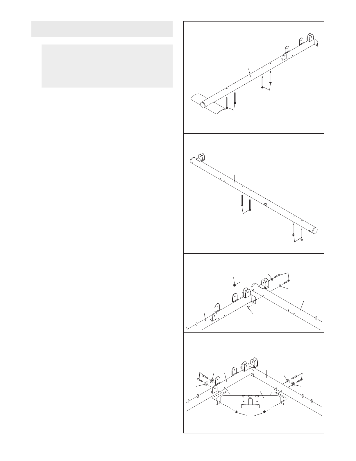
Frame Assembly
.
1
Before beginning assembly, make sure you
understand the information in the box on
page 5. See the PART IDENTIFICATION
CHART in the center of this manual for help
identifying small parts.
1
1
Insert four M8 x 72mm Carriage Bolts (69) up
through the Right Base (1).
helpful to place a piece of tape over each bolt
head to hold it in place.
2. Insert four M8 x 72mm Carriage Bolts (69) up
through the Left Base (25). Note: It may be help-
ful to place a piece of tape over each bolt
head to hold it in place.
3. Attach the Right Base (1) to the Left Base (25)
with two M8 x 77mm Bolts (82), two M8 Washers
(98), and two M8 Nylon Locknuts (91). Do not
tighten the Locknuts yet.
Note: It may be
69
69
2
25
69
69
3
91
98
82
Attach the Center Base (52) to the Right Base (1)
4.
with two M8 x 77mm Bolts (82), two M8 Washers
(98), and an M8 Nylon Locknut (91). Do not
tighten the Bolts yet.
Attach the Center Base (52) to the Left Base
(25) in the same manner
.
98
25
1
91
4
91
52
25
98
82
98
98
82
98
1
6
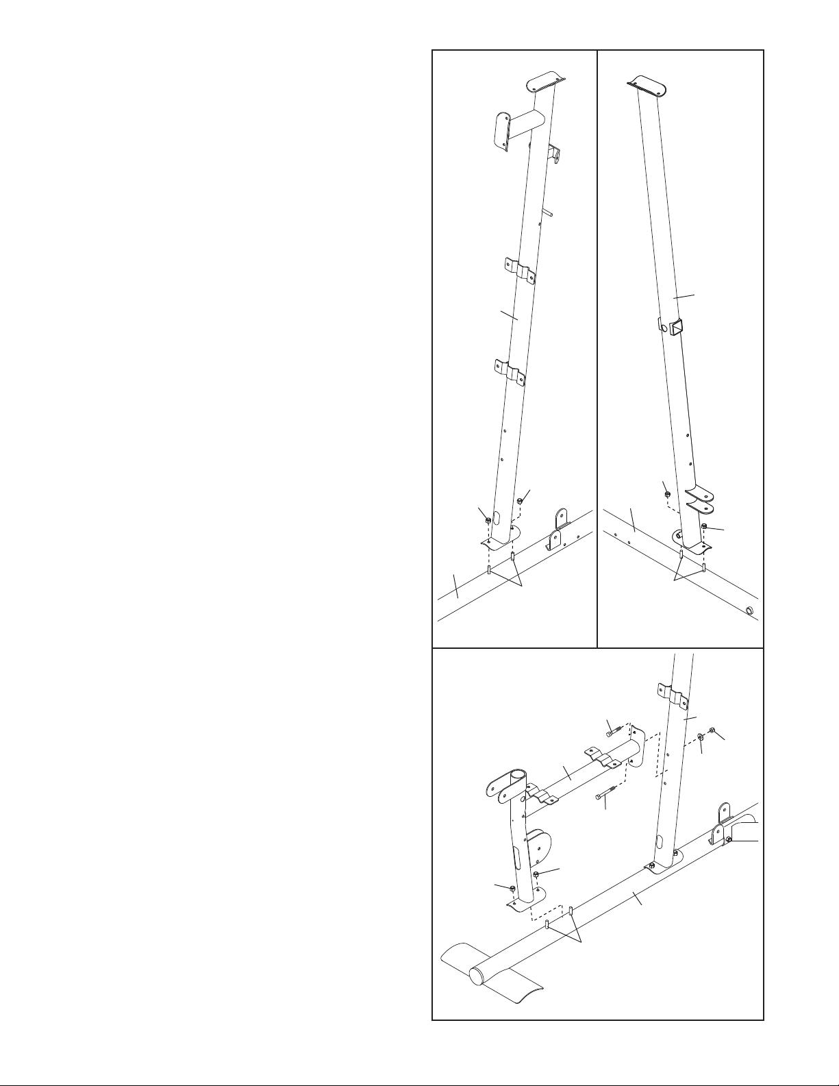
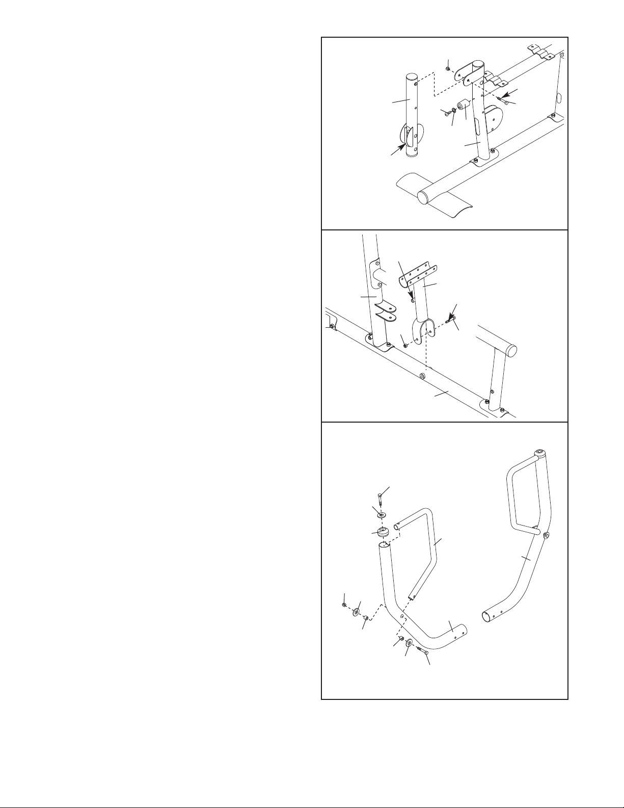
5. See drawing A. Attach the Right Upright (2) to
the Right Base (1) with the two indicated M8 x
2mm Carriage Bolts (69) and two M8 Nylon
7
Locknuts (91).
See drawing B. Attach the Left Upright (26) to
the Left Base (25) with the two indicated M8 x
72mm Carriage Bolts (69) and two M8 Nylon
Locknuts (91). Do not tighten the Locknuts yet.
Do not tighten the Locknuts yet.
5A B
26
2
6. Attach the Right Seat Frame (3) to the Right
Base (1) with the two indicated M8 x 72mm
Carriage Bolts (69) and two M8 Nylon Locknuts
(91). Do not tighten the Locknuts yet.
Attach the Right Seat Frame (3) to the Right
Upright (2) with an M8 x 77mm Bolt (82), an M8 x
95mm Bolt (83), an M8 Washer (98), and an M8
Nylon Locknut (91).
yet.
Do not tighten the Locknut
91
91
1
69
6
82
3
83
91
91
91
25
91
69
2
91
98
1
69
7
7. Attach the Left Seat Frame (27) to the Left Base
(25) with the two indicated M8 x 72mm Carriage
olts (69) and two M8 Nylon Locknuts (91). D
B
not tighten the Locknuts yet.
Attach the Left Seat Frame (27) to the Left
Upright (26) with two M8 x 77mm Bolts (82), two
M8 Washers (98), and two M8 Nylon Locknuts
(91). Do not tighten the Locknuts yet.
o
7
98
1
9
98
26
82
8
7
2
2
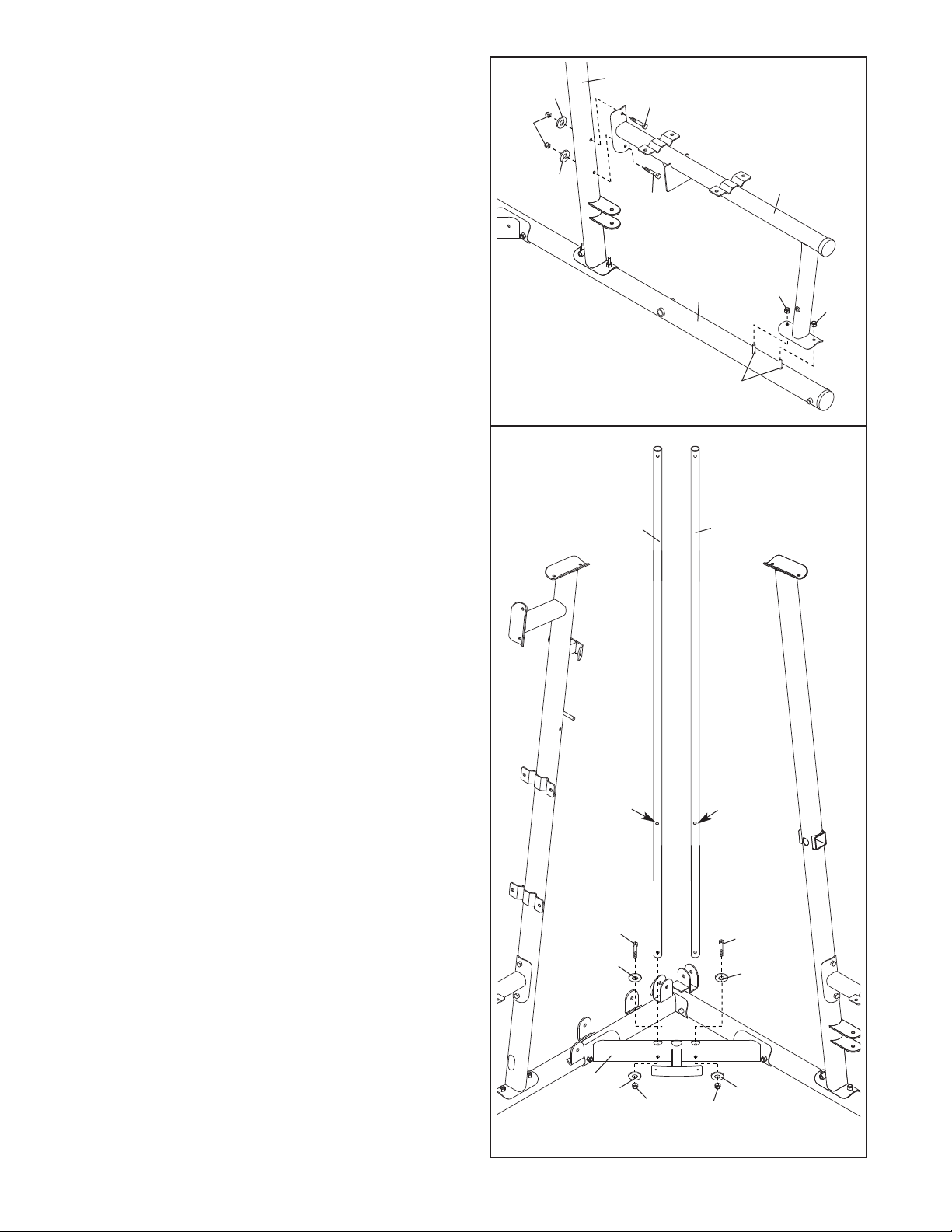
8. Orient the Weight Guides (44) with the indicated
holes closer to the bottom. Attach the Weight
Guides inside of the Center Base (52) with two
M8 x 77mm Bolts (82), four M8 Washers (98),
and two M8 Nylon Locknuts (91).
25
8
44
44
91
91
69
Hole
82
98
52
98
91
Hole
82
98
98
91
8
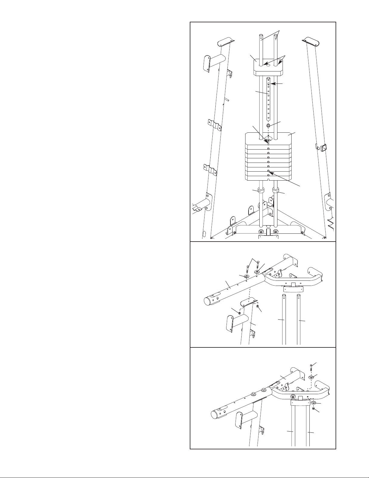
9. Slide two Weight Bumpers (45) onto the Weight
Guides (44). Slide the eight Weights (55), with the
in holes on the indicated side, onto the Weight
p
Guides.
Press the Weight Tube Bumper (46) into the
Weight Tube (47). Insert the Weight Tube into the
stack of Weights (55).
Weight Tube sits in the groove in the top
Weight.
Grease the indicated holes in the Top Weight (56)
with an included grease pack. Slide the Top
Weight onto the Weight Guides (44).
Make sure the pin on the
9
56
47
Groove
44
Grease
Pin
46
55
10. Attach the Right Top Frame (5) to the Right
Upright (2) with two M8 x 77mm Bolts (82), two
M8 Washers (98), and two M8 Nylon Locknuts
(91). Do not tighten the Locknuts yet. Make
sure the Weight Guides (44) are behind the
Right Top Frame.
1. Attach a Weight Guide (44) to the Right Top
1
Frame (5) with an M8 x 77mm Bolt (82), two M8
Washers (98), and an M8 Nylon Locknut (91). Do
not tighten the Locknut yet.
10
1
45
82
98
98
5
91
91
44
2
1
5
45
Pin
Holes
44
82
98
Repeat this step with the other Weight Guide
(44).
98
91
44
44
9
12. Attach the Left Top Frame (36) to the Right Top
Frame (5) with four M8 x 77mm Bolts (82), two
8 Washers (98), a Support Plate (31), and four
M
M8 Nylon Locknuts (91).
ocknuts yet.
L
Do not tighten the
12
31
36
91
5 91
91
82
98
98
2
8
13. Attach the Left Top Frame (36) to the Left Upright
(26) with two M8 x 77mm Bolts (82), a Support
Plate (31), and two M8 Nylon Locknuts (91).
not tighten the Locknuts yet.
14. Orient the Butterfly Frame (14) as shown. Attach
the Butterfly Frame to the Right Upright (2) with
two M8 x 70mm Bolts (85), two M8 Washers (98),
and two M8 Nylon Locknuts (91). Do not tighten
the Locknuts yet.
Attach the Butterfly Frame (14) to the Right Top
Frame (5) with two M8 x 77mm Bolts (82), two
M8 Washers (98), and two M8 Nylon Locknuts
(91).
Tighten the M8 Nylon Locknuts (91) used in
steps 3–14.
Do
13
14
85
98
91
98
82
36
31
91
91
82
98
5
91
14
26
98
91
2
Arm Assembly
15. Wet the lower end of the Left Butterfly Arm (6)
with soapy water. Slide a Large Foam Pad (15)
onto the Left Butterfly Arm.
Note: an entire grease packet should be used
for this step. Grease an M10 x 85mm Bolt (74)
and the indicated edges of two Arm Bushing (23)
with a grease packet. Attach the Left Butterfly
Arm (6) to the Butterfly Frame (14) with the Bolt
(74), an M10 Large W
Bushings, and an M10 Nylon Locknut (90).
sure the bolt head fits inside of the hole in the
Butterfly Frame.
Repeat this step with the Right Butterfly
(7).
asher (100), the two
Arm
Make
Arm
10
15
Grease
74—Grease
Grease
23
23
6
15
7
14
100
90
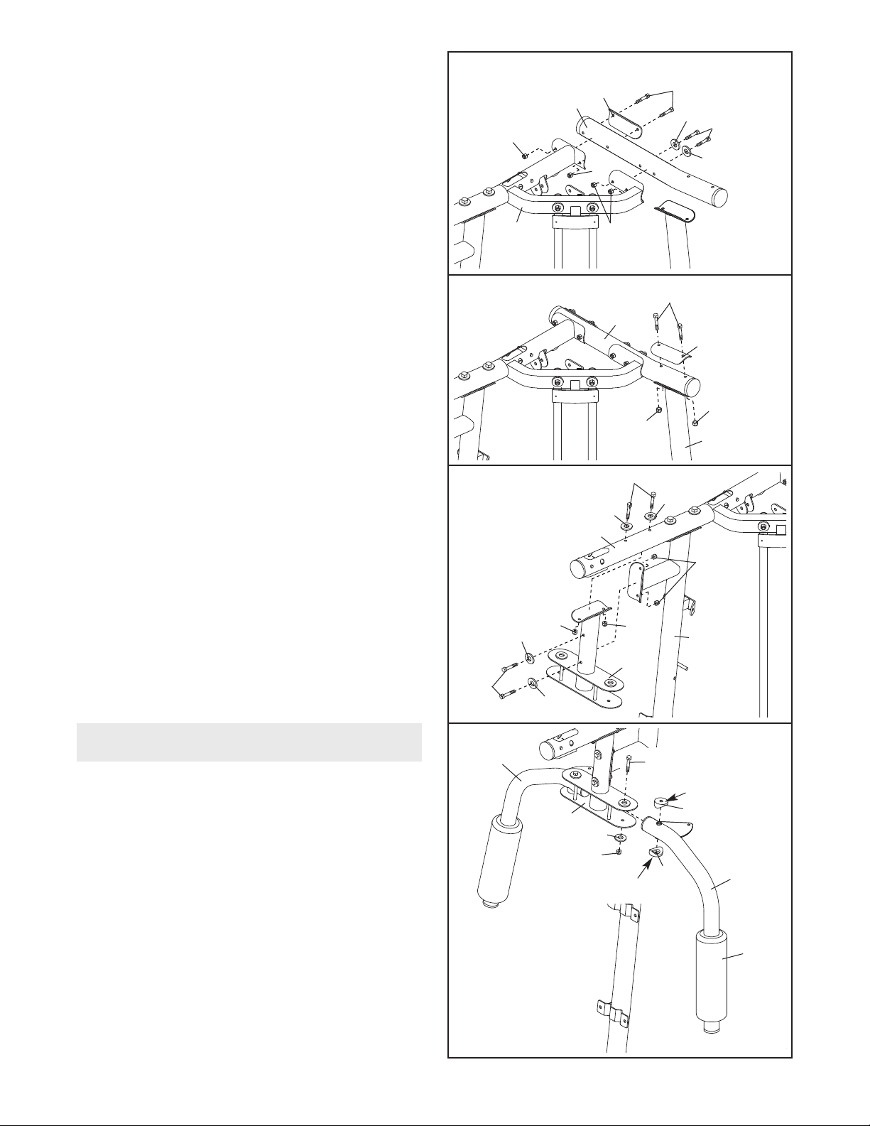
16. Attach the Leg Bumper (59) to the Right Seat
Frame (3) with an M4 x 16mm Self-tapping Screw
89) and an M4 Washer (96).
(
16
90
rease an M10 x 72mm Bolt (60). Attach the Leg
G
Lever (4) to the Right Seat Frame (3) with the
Bolt and an M10 Nylon Locknut (90). Make sure
the “U”-rod is on the indicated side of the Leg
Lever. Do not overtighten the Locknut; the
Leg Lever must be able to pivot easily.
17. Grease an M10 x 106mm Bolt (72). Orient the
Press Frame (29) so that the welded tube is on
the side toward the Left Upright (26). Attach the
Press Frame to the Left Base (25) with the Bolt
and an M10 Nylon Locknut (90).
tighten the Locknut; the Press Frame must be
able to pivot easily.
Do not over-
17
26
“U”-rod
4
Tube
90
9
8
6
9
29
Grease
72
Grease
60
59
3
18. Attach a Press Handle (32) to a Press Arm (30)
with an M10 x 65mm Bolt (77), two M10 Washers
(99), two M10 x 12mm Spacers (101), and an
M10 Nylon Locknut (90).
Attach a Press Arm Cap (34) to the Press Arm
(30) with an M10 x 45mm Button Bolt (81) and an
M10 Large Washer (100).
Repeat this step with the other Press Arm
(30).
18
90
100
34
99
101
25
81
32
30
30
101
99
77
11
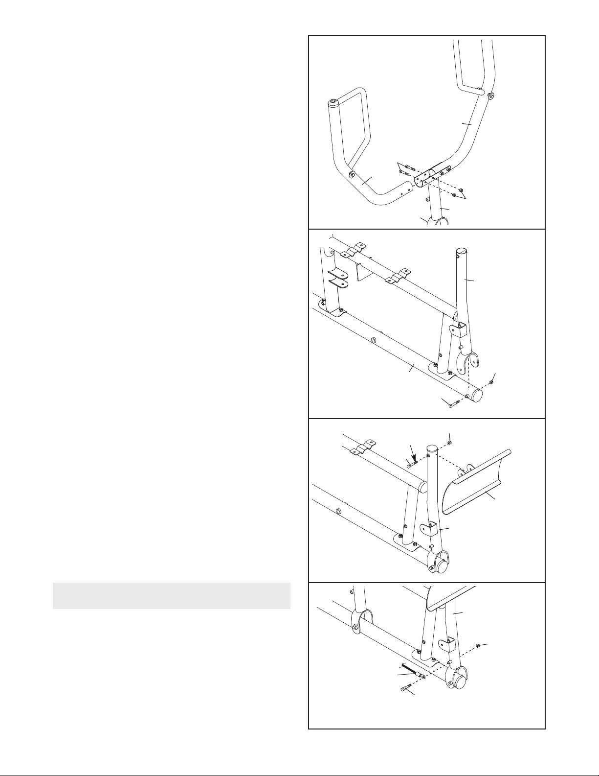
19. Attach a Press Arm (30) to the Press Frame (29)
with two M8 x 66mm Bolt (86) and two M8 Nylon
ocknuts (91).
L
epeat this step with the other Press Arm
R
(30).
19
30
86
30
91
29
20. Grease an M10 x 106mm Bolt (72). Attach the
Leg Press Frame (28) to the Left Base (25) with
the Bolt and an M10 Nylon Locknut (90).
overtighten the Locknut; the Leg Press Frame
must be able to pivot easily.
21. Grease an M10 x 75mm Bolt (76). Attach the
Foot Plate (38) to the Leg Press Frame (28) with
the Bolt and an M10 Nylon Locknut (90). Make
sure the decal on the Foot Plate is right side
up. Do not overtighten the Locknut; the Foot
Plate must be able to pivot easily.
Do not
20
21
28
90
25
72
90
Grease
76
38
Cable Assembly
22. See the
27 as you assemble the cables and to identify
the cables.
Locate the Press Cable (109).
to the Leg Press Frame (28) with an M8 x 86mm
Shoulder Bolt (37) and an M8 Nylon Locknut (91).
Do not overtighten the Locknut; the Cable
must be able to pivot easily.
CABLE DIAGRAMS
on pages 26 and
Attach the Cable
28
22
28
91
109
37
12
 Loading...