

Page 1

Manual - Technical Documentation
ATEX
Watson-Marlow MasoSine - Pumps
EC 25 / EC 40 / EC 60
Revision 4.4 / November 2010 1
Page 2

Content
Technical datasheet ........................................................................................................................................4
1 GENERAL ............................................................................................................ 5
2 PURPOSE ............................................................................................................ 5
3 FUNCTIONING PRINCIPLE................................................................................. 5
4 SAFETY INSTRUCTIONS.................................................................................... 5
4.1 Basic safety instructions......................................................................................................................5
4.2 Safety symbols ...................................................................................................................................5
4.3 Obligation of the operator....................................................................................................................5
4.4 Organizational measures ....................................................................................................................5
4.5 Obligation of the personnel .................................................................................................................6
4.6 Training of the personnel ....................................................................................................................6
4.7 Informal safety measures....................................................................................................................6
4.8 Dangers when handling the machine..................................................................................................6
4.9 Safety measures in normal operation .................................................................................................6
4.10 Protective devices ...............................................................................................................................6
4.11 Dangers due to hazardous pumped material......................................................................................6
4.12 Dangers due to electrical energy ........................................................................................................6
4.13 Dangers due to hydraulic energy ........................................................................................................6
4.14 Special danger points..........................................................................................................................6
4.15 Constructional changes to the machine..............................................................................................7
4.16 Noise of the machine ..........................................................................................................................7
4.17 Maintenance and repair, troubleshooting............................................................................................7
4.18 Maintenance of the bearings...............................................................................................................7
4.19 Cleaning the machine .........................................................................................................................7
4.20 Faults...................................................................................................................................................7
4.21 Use as intended ..................................................................................................................................7
5 SAFETY INSTRUCTIONS (ATEX)....................................................................... 7
5.1 Safety signs.........................................................................................................................................7
5.2 Pump classification .............................................................................................................................7
5.3 Zone classification...............................................................................................................................8
5.4 Classification of the ex-atmospheres ..................................................................................................8
5.5 Ignition protection ................................................................................................................................8
5.6 Temperature classes...........................................................................................................................8
5.7 Limit values for the pump ....................................................................................................................8
5.8 Grounding the pump ...........................................................................................................................8
5.9 Material properties ..............................................................................................................................8
5.10 Pressure Conditions............................................................................................................................8
5.11 Maintenance / Repair ..........................................................................................................................9
5.12 Cleaning ..............................................................................................................................................9
5.13 Medium to be pumped ........................................................................................................................9
5.14 Coupling ..............................................................................................................................................9
5.15 Drive ....................................................................................................................................................9
6 WARRANTY AND LIABILITY.............................................................................. 9
7 TRANSPORT INSTRUCTIONS ........................................................................... 9
8 INSTALLATION ................................................................................................. 10
9 CONNECTION TO THE PIPING ........................................................................ 10
10 POSSIBLE CONNECTION POSITIONS ......................................................... 10
Revision 4.4 / November 2010 2
Page 3

11 CHANGING THE CONNECTION POSITION.................................................. 11
12 CHANGING THE DIRECTION OF ROTATION............................................... 11
13 IMPORTANT: OBSERVE BEFORE START-UP!............................................ 11
14 CLEANING ...................................................................................................... 12
14.1 Cleaning in own circuit with water, alkali, acid ..................................................................................12
14.2 Cleaning in the CIP circuit.................................................................................................................12
14.3 Manual cleaning ................................................................................................................................12
14.4 Sterilization........................................................................................................................................12
15 OIL CHANGE .................................................................................................. 13
15.1 Filling volumes ..................................................................................................................................13
16 DISPOSAL ...................................................................................................... 13
17 SPARE PARTS ............................................................................................... 13
18 TAKING OUT OF SERVICE............................................................................ 13
18.1 Provisional taking out of service .......................................................................................................13
18.2 Final putting out of service ................................................................................................................13
19 TROUBLESHOOTING .................................................................................... 14
20 ADJUSTING DIMENSION............................................................................... 15
21 TIGHTENING TORQUES ................................................................................ 16
22 DISMANTLING ............................................................................................... 17
23 DISMANTLING „LIP SEAL SYSTEM“ ........................................................... 19
24 DISMANTLING „MECHANICAL SEAL SYSTEM“ ......................................... 20
25 ASSEMBLY..................................................................................................... 21
25.1 Assembly „Rotor-Assembly“..............................................................................................................21
26 PUMP SIZES ................................................................................................... 22
26.1 Cross section drawing EC 25 with Lip Seal System.........................................................................22
26.2 Cross section drawing EC 25 Mechanical Seal System ...................................................................22
26.3 Cross section drawing EC 40 with Lip Seal System.........................................................................23
26.4 Cross section drawing EC 40 with Mechanical Seal System............................................................23
26.5 Cross section drawing EC 60 with Lip Seal System.........................................................................24
26.6 Cross section drawing EC 60 with Mechanical Seal System............................................................24
26.7 Parts list for an EC 25 / EC 40 / EC 60 Pump...................................................................................25
26.8 Parts list for the Lip Seal System EC 25 / EC 40 / EC 60.................................................................25
26.9 Parts list for the Mechanical Seal System EC 25 / EC 40 / EC 60 ...................................................25
27 CODE-STRUCTURE FOR SPARE PART ORDERS ...................................... 26
28 DIMENSIONAL DRAWINGS........................................................................... 27
28.1 Dimension table for pump with German Milk Fittings .......................................................................27
28.2 Dimension table for pump with TRI-CLAMP (TC).............................................................................28
28.3 Dimension table for pump with RJT ..................................................................................................28
28.4 Dimension table for pump with SMS (Swedish norm) ......................................................................28
28.5 Dimension table for pump with SMS (French norm).........................................................................28
Revision 4.4 / November 2010 3
Page 4

Technical datasheet
Please remove all technical information from the technical Data Sheet.
For spare parts ordering refer to software component list.
If you have problems to identify parts, please refer the drawing and parts list. In case of any questions
please contact the Technical Support
Revision 4.4 / November 2010 4
Page 5

1 General
The operating instructions apply for the Watson-Marlow MasoSine:
EC 25 / EC 40 / EC 60
The operating instructions must be read before installing the pumps. Please observe the safety instructions and the safety
regulations.
2 Purpose
The purpose of your pump is defined exactly in the delivery note. The warranty becomes null and void following any changes to
the purpose, including changes to components and materials.
Always consult the manufacturer before any changes are to be made to the pump, its components or application.
3 Functioning principle
The functioning principle of the Watson-Marlow MasoSine Pump is ingeniously simple. The pump consists of modular
components to allow for easy assembly, disassembly and in-line maintenance, preventing the need to return the pump for
factory repair. The MASO-Sine pump’s exclusive sinusoidal rotor creates four symmetrical pumping chambers that draw product
through the pump. As product is drawn through in a continuous flow, it encounters the scrapergate and is discharged by product
flowing behind it creating a continuos pulse-free laminar flow. The MASO-Sine pump’s large pumping chambers maintain
constant volumetric displacement throughout the entire pumping cycle that eliminates product compression and minimizes
damage to large particles.
4 Safety instructions
4.1 Basic safety instructions
Failure to follow these safety instructions may result in damage to property, personal injury or death.
A basic requirement for safe handling and troublefree operation of this machine is knowledge of the basic safety instructions and
practice of the safety regulations.
These operating instructions contain the most important instructions to operate the machine safely.
These operating instructions, especially the safety instructions, must be observed by all persons who work on the machine.
Moreover the rules and regulations for accident prevention applicable at the place of use must be complied with.
The following safety instructions must be observed absolutely.
They are an essential and indispensable part of the user documentation. Non-compliance can result in loss of warranty claims.
It is recommended in the interest of all involved to enter all installation measures, maintenance, fault and repair cases, training
courses, instructions and special occurrences in a logbook assigned to the machine.
4.2 Safety symbols
Safety instructions that must be followed. Failure to comply with these instructions may result in damage
to property, personal injury or death.
Safety instruction for electrical voltage. Failure to comply with these instructions may result in damage to
property, personal injury or death.
CCAAUUTTIIOONN
Safety instruction to prevent damage to the pump or system.
4.3 Obligation of the operator
Only persons who are familiar with the basic regulations concerning working safety and accident prevention, have read and
understand this manual, and are instructed in handling the MASO-Sine pump are to be allowed to on or with the machine.
The safety-conscious working of the personnel should be checked at regular intervals.
4.4 Organizational measures
Any required personal protective equipment shall be provided by the operator.
All existing safety devices shall be checked regularly.
Revision 4.4 / November 2010 5
Page 6

4.5 Obligation of the personnel
All persons who are authorized to work with or on the machine obligate themselves to observe the basic regulations concerning
working safety and accident prevention before starting work. All persons to read and understand the safety chapter and warning
notes in the operating instructions and to confirm by their signature that they have understood these. If there are any questions
regarding this manual or the proper use and maintaining of the MASO-Sine pump, contact the factory before use..
4.6 Training of the personnel
Only trained and instructed personnel may work with or on the machine. The responsibilities of the personnel shall be defined
clearly for assembly, disassembly, start-up, operation, maintenance and repair.
Personnel under training may work on the machine only under supervision of an experienced person.
4.7 Informal safety measures
The operating instructions must be kept on file and be made readily available to all persons who work with or on the MASO-Sine
pump. The generally valid as well as the local regulations for accident prevention and environmental protection shall be provided
and observed in addition to the operating instructions. All safety and danger warnings on the machine shall be kept in legible
condition. Contact the factory if additional manuals are required.
4.8 Dangers when handling the machine
The Watson-Marlow MasoSine Pump is built according to the state of the art and the recognized safety engineering rules at
the time of manufacture. Danger to life and limb of the user or other persons or impairments to the machine or to other assets
can arise if safety instructions are not followed.
The machine must be used only:
• for the intended use delivery note
• in perfect safety engineering condition.
Faults which can impair safety must be rectified immediately.
4.9 Safety measures in normal operation
Operate the machine only if all safety devices are fully functioning. Before switching the machine on make sure that the starting
machine can endanger no one. At least once per shift inspect the machine for “externally detectable damage” and for
functioning of the safety devices.
4.10 Protective devices
All protective devices must be attached correctly and functioning before every start-up.
Protective devices may be removed only
- After standstill and simultaneous protection against restarting the machine. Always follow proper LOCKOUT – TAGOUT
procedures.
- The pump is not under pressure.
- All components are allowed to reach a comfortable temperature.
4.11 Dangers due to hazardous pumped material
In the case of hazardous pumped material as defined by MSDS, the corresponding regulations must be followed.
4.12 Dangers due to electrical energy
Follow proper LOCKOUT – TAGOUT procedures before handling electrical components.
Have work on the electrical supply performed only by a qualified electrician.
Check the electrical equipment of the machine regularly. Rectify loose connections and scorched cables
immediately.
Keep the control cabinet closed always. Access is allowed only to authorized personnel
Only qualified personnel should handle electrical components.
4.13 Dangers due to hydraulic energy
Only personnel with special knowledge and experience in hydraulics may work on hydraulic devices.
Relieve the pressure in system sections and pressure lines to be opened before starting repair work. Replace hydraulic hose
lines at appropriate intervals, even if no safety-relevant defects are detectable.
4.14 Special danger points
This pump and equipment utilize rotating components that may pose
potential injury. The user must protect the pump so that there is no
exposure to rotating components. In the case of work on the stationary
rotor, the drive must be secured against unintentional switching on.
Follow proper LOCKOUT – TAGOUT procedures. Increased danger
exists with dismantled pipes and opened pump.
Revision 4.4 / November 2010 6
Page 7
4.15 Constructional changes to the machine
Make no changes, attachments or conversions to the machine without prior written approval of the manufacturer. All conversion
measures require the written approval of the Watson-Marlow MasoSine Company. Damaged or improperly functioning parts
should be immediately replaced. Use only original MASO-Sine parts. Use of parts not supplied by MASO-Sine or other
aftermarket parts will void all warranties. Aftermarket parts are not authorized by Watson-Marlow MasoSine and void all
certifications such as 3-A, USDA and FDA.
4.16 Noise of the machine
The continuous sound level proceeding from the pump is less than 70 dB(A). A higher sound pressure level that causes noise
deafness can arise depending upon the local conditions. In this case protect the operating personnel with corresponding
protective equipment / protective measures.
4.17 Maintenance and repair, troubleshooting
Perform specified adjustment, maintenance and inspection work in a timely manor to prevent possible damage. Inform operating
personnel before starting the maintenance and repair work. Protect all plant parts and operating media connected before and
after the machine such as compressed air and hydraulics and similar against unintentional start-up. Follow proper LOCKOUT –
TAGOUT procedures before performing any maintenance. In all maintenance, inspection and repair work switch
the machine free of voltage and secure the main switch against unexpected starting. Fasten and secure larger
assemblies on replacement carefully to lifting gear. Be sure all fasteners are tightened to proper specifications. Use
only original spare parts.
After ending the maintenance work check the safety devices for function.
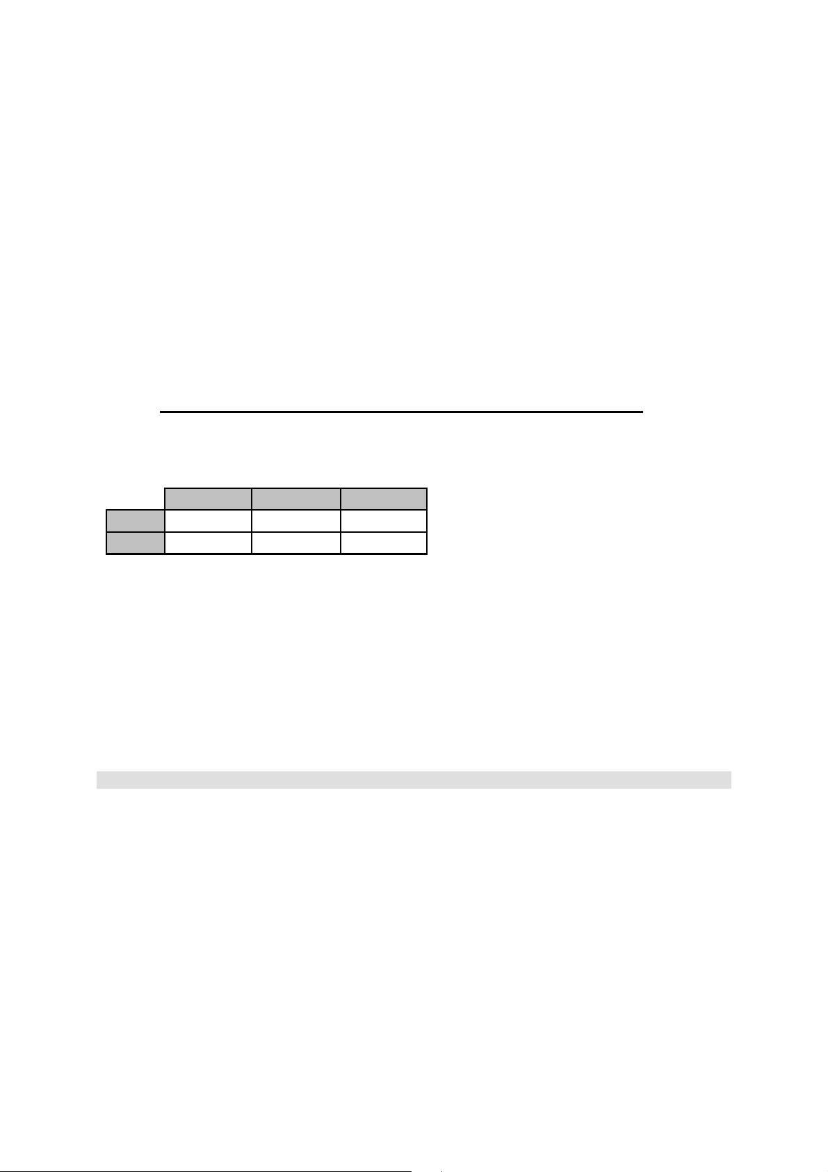
4.18 Maintenance of the bearings
• For pumps in series, EC 25 and EC 40 both bearings must be replaced by new ones after running for 10,000 hours!
• For pumps in series EC 60, please refer to the enclosed table:
200 rpm 400 rpm 600 rpm
3 bar
6 bar
4.19 Cleaning the machine
Handle substances and materials used correctly, especially
- when working on lubricating systems
- when cleaning with solvents.
10000 hours
9199 hours 6133 hours
4.20 Faults
In the case of operating faults switch off the machine and secure it against unauthorized or inadvertent starting up again.
4.21 Use as intended
The accurate intention is listed in the order confirmation. Another use or use going beyond this is not as intended.
If you want to change the product, the pressure, the speed or the temperature, you must firstly consult us or one of our
representatives.
5 Safety instructions (ATEX)
Watson-Marlow MasoSine - Pump used in production machinery with explosive mixtures will be equipped accordingly in the
factory.
5.1 Safety signs
Grounding symbol
5.2 Pump classification
The pumps are only designed for jobs lasting several days and are therefore assigned to the Device Group II – Application field
“dust – or gas – explosive areas”!
Revision 4.4 / November 2010 7
Page 8
5.3 Zone classification
The Watson-Marlow MasoSine - Pumps can be used in explosive areas of the zone 1 / 21.
This corresponds to the category 2 G / D.
It is expressly forbidden to use the pump(s) in the zone 0!
5.4 Classification of the ex-atmospheres
A distinction is made between dust and gas explosive atmospheres. In the model code, the atmosphere is abbreviated with G
(Gas) and D (Dust). Watson-Marlow MasoSine - Pumps are only designed for the explosive atmospheres G (Gas) and D
(Dust)!
5.5 Ignition protection
Our pumps are subject to ignition protection "c" constructive safety according to the standard for "non-electric appliances for use
in explosion-risk areas" EN 13463-5
5.6 Temperature classes
For product temperature up to max. 95°C: EX II 2 G c T4
EX II 2 D c T=120°C
5.7 Limit values for the pump
The limit values for the pump (max. speed, max. pressure, max. temperature) are stated in the data sheet (see page 4). These
limit values must never be exceeded under any circumstances! This applies in particular when using a frequency converter.
If the pumps are supplied without a drive, the following values apply!
EC25 EC40 EC60
max. Pressure * 6 bar 6 bar 6 bar
max. Speed * 600 rpm 600 rpm 600 rpm
max. Temperature *
95°C* 95°C* 95°C*
Ambient temperature -12°C bis +40°C -12°C bis +40°C -12°C bis +40°C
* depending on the rating of the pump (pls. see order confirmation)
5.8 Grounding the pump
All supplied pumps are equipped with a grounding option.
In particular in ex-areas, the pump must be grounded by fixing a grounding cable to the corresponding position (see diagram).
In addition to the grounding of the pump, the motor also needs to be grounded! If the drive is not grounded, the pump aggregate
may not be operated.
Grounding
5.9 Material properties
Plastic parts that are fitted inside the pump react more to temperature changes that stainless steel parts. For this reason, the
specified maximum medium temperature (Tm=95°C), for which the pump is designed, may not be exceeded. If the specified
temperature is exceeded, this may cause a linear expansion and may block single components; this in turn could cause the
pump to fail or could result in damage to parts of the pump. Also, excessive temperatures can accelerate the wear of dynamic
parts and therefore reduce the lifespan of the plastic parts.
Corrosion may occur to the Power Frame of the pump if the paintwork is damaged. Corrosion represents a hazard for the use of
pumps in explosive areas (for measures, see Troubleshooting Chap. 21).
5.10 Pressure Conditions
To avoid any over-pressure in the pump as a result of a closed pressure line, a pressure controller must be installed.
Revision 4.4 / November 2010 8
Page 9

5.11 Maintenance / Repair
• The Filling of the pump is only permitted outside the explosion aria. Tools that are used should in compliance with
ATEX.
• The pump aggregate always needs to be kept clean of dust with a damp cloth to prevent the dust from smouldering.
• The rinsing channels in the power frame must always be checked for blockages and if necessary cleaned.
5.12 Cleaning
Caution! No solvent cleaning agents may be used to clean the pump as this could create an uncontrollable explosive
atmosphere.
5.13 Medium to be pumped
Chemicals that are combustible below the temperature 120 degrees Celsius (T4/T=120°C) and Carbon disulphide must not be
pumped.
5.14 Coupling
If the pump is used in an explosion-risk area, the pump must only be coupled to the drive by means of an elastic, positive
coupling with ATEX certification, at least corresponding to the supplied pump. Chains, toothed belts, v-belts or similar equipment
which may transmit radial forces on the bearings should not be used.
5.15 Drive
Any preceding reduction gears and/or control units must have the corresponding ATEX certification, at least corresponding to
the supplied pump. Combustion engines must never be used!
For operation with a frequency converter, this must either be installed outside the ex-zone, or have the same ATEX certification
corresponding to the delivered pump. In any case the converter must have the properties required for operation in ex-zones, for
example, temperature monitoring, speed limitation, etc.
6 Warranty and liability
Basically our “General sales and delivery conditions” apply.
These are available to the operator at the latest since conclusion of the contract.
Warranty and liability claims for personal and material damage are excluded if they are attributable to one or several of the
following causes:
- Use of the machine not as intended
- Incorrect installation, operation and maintenance of the machine
- Operating the machine with defective safety devices or not correctly attached or not functioning safety and protective
- Non-compliance with the instructions in the operating instructions regarding
transport,
storage,
installation,
start-up,
operation, maintenance and setting of the machine.
- Unauthorized constructional changes to the machine
- Insufficient monitoring of machine parts subject to wear
- Incorrectly performed repairs
- Cases of catastrophe due to effect of foreign bodies and acts of God.
Watson-Marlow MasoSine grants no warranty on this documentation as well as no implicit warranties on commercially
customary quality and suitability for a certain application.
Watson-Marlow MasoSine undertakes no liability for errors contained in it or consequential damage occurring by chance
arising due to the design, performance and the use of this documentation.
This publication contains own information protected by copyright. All rights are reserved.
This publication may be neither photocopied, nor duplicated nor translated without previous agreement of Watson-Marlow
MasoSine. Rights reserved to make changes in these operating instructions.
devices
7 Transport instructions
The choice of the means of transport is according to the size of the pump and of the drive. The pump must be suspended
correctly for transport. The crane/forklift truck and the ropes/belts must be sufficiently dimensioned. If the pump is transported
with a lift truck or a forklift truck, it must be noted that the console centre point is not automatically the centre of gravity.
Wrong! Rright!
Revision 4.4 / November 2010 9
Page 10

8 Installation
CCAAUUTTIIOONN CCAAUUTTIIOONN
CCAAUUTTIIOONN
CCAAUUTTIIOONN
CCAAUUTTIIOONN CCAAUUTTIIOONN
DO NOT LET RUN THE P
UMP
CAUTION!
Cavitation destroys the pump!
The motor shaft and pump shaft connection
must be protected against contact!
Place the pump on a level ground.
Do not start without the protection against contact!!
The foundation should be dimensioned sufficiently for the weight of the pump.
There should be sufficient space for maintenance work around the pump.
It must be guaranteed that the motor receives an adequate air supply.
If the pump is used in explosion endangered rooms, an Ex protected motor must be
used.
The total unit must be protected against static charge.
Align the shaft of the pump with the shaft of the drive.
WITHOUT COUPLING GUARD!
9 Connection to the piping
Before connection clean the piping and remove foreign bodies.
(e.g. there can still be residues in the pipes due to welding work).
Fit elastic intermediate members (compensators) between pump and fixed piping on the suction
and pressure side. This should prevent vibrations of the pump being transmitted to the piping
system.
Forces and torques acting from the piping on the pump connections (e.g. due to distortion,
expansion due to temperatures etc.) must be avoided.
The pressure line should point upwards, so that later residual liquid can always flow back into the
pump. Thus total dry running is avoided. Further it facilitates the later suction process.
The operator has to ensure that an inadmissible pressure rise (above the pressure agreed in the
order and listed in the technical data) is not possible.
The SINUS pumps normally run with such a low resonant frequency that no corresponding
damage is caused. However, particularly when running with converters, certain frequencies can
cause interfering vibrations which must be avoided. It is important during initial commissioning to
ascertain whether such vibrations exist and to define them accordingly, so that the frequency
converter can then be programmed to avoid these frequencies. Similarly, interference from
cavitation or rigid lines must be ruled out.
The operator has to ensure that the pump can work free of cavitation!
10 Possible connection positions
Counterclockwise rotation of the rotor and motor Clockwise rotation of the rotor and motor
Revision 4.4 / November 2010 10
Unless otherwise ordered, the pump is delivered in 10-2 position.
Page 11

Changing the direction of rotation for a EC 25, EC 40 and
EC 60.
11 Changing the connection position
The standard nozzle configuration is set at the 10-2 position from the
Pos. 10
Pos. 9
Pos. 30
in the vertical position and reinstall on the pump housing. Tighten the screws Pos.9 according the specified torque. Mind that the shim
kit, Pos. 24 is on the housing.
Torque for Pos. 9: EC 25 25 Nm EC 40 50 Nm EC 60 90 Nm
Observe that the pump is filled with product before starting to facilitate suction and to avoid dry run. (see chapter 12)!
When the connection position is changed, the motor must be protected
against unintentional switching on!!
12 Changing the direction of rotation
factory. To change the nozzle position, all internal parts must first be
removed as in illustration 001. Remove the screw, Pos. 30, as well
as the screws Pos.9 (2 pcs.). The housing and shaft can now be
removed from the baseplate. Note: once removed from the base, the
housing will be free and should be secured to prevent possible
damage or personal injury. CAUTION: EC 40 AND EC 60
HOUSINGS WILL BE HEAVY. Rotate the pump housing into the
desired position and replace the screws to reinstall the baseplate.
The bearing assembly musty now be rotated so that the vent and oil
sight glass are in the proper position. Remove the screws, Pos.10 (4
pcs.) and remove the shaft and bearing housing assembly from the
pump housing. Rotate the bearing housing assembly until the vent is
Due to construction, the pump is able to turn clockwise as well as
counter clockwise. For doing this any conversion or modification is not
necessary.
All you have to do is changing the direction of the gear motor.
13 Important: Observe before start-up!
If you have performed cleaning or repair work or make the first start-up, check before start-up that all screws are correctly and
completely tightened.
Observe the corresponding regulations in the case of hazardous pumped material (according to ArbStoffV).
The pump can possibly be contaminated by transport, therefore remove the pump cover and clean if necessary before start-up.
Before you start up the pump, convince yourself once again that the scraper and the guide cartridge are in the correct position in
relation to the pressure side (see change of direction of rotation).
CCAAUUTTIIOONN
The operator must ensure that the pump is installed in an appropriate position with all necessary
safety precautions (sensors, switches, pressure gauges, etc.)!
Liquid level
Revision 4.4 / November 2010 11
The pump must always be filled with the
corresponding medium before commissioning
and during operation, with the liquid level
above the rotor (see diagram).
Never let the pump run dry!!!
Page 12

CCAAUUTTIIOONN
CCAAUUTTIIOONN CCAAUUTTIIOONN
The motor must be connected by an expert according to DIN EN 60204.
Make sure before start-up that all valves on the pressure and suction side are open. The pump
may not pump against a closed valve without overpressure valve.
If the pump leaks, end operation as quickly as possible to replace the damaged sealing elements.
The operator must ensure that the pump can work free of cavitation.
Cavitation destroys the pump.
14 Cleaning
All Watson-Marlow MasoSine Pumps are fully capable of CIP cleaning. Please observe our CIP cleaning regulations.
14.1 Cleaning in own circuit with water, alkali, acid
1. Set control gear to maximum speed (at least 400 rpm).
2. Choke after the pump so that a counterpressure of 3 to 4 bar (44 to 58 psi) arises.
3. Should the required cleaning effect not be achieved after this process,
it is necessary to dismantle the pump.
This is done in a few minutes as described in detail in the operating instructions.
Manual cleaning of the pump can be performed after complete dismantling of the pump.
Pay attention to parts sensitive to breakage!!
14.2 Cleaning in the CIP circuit
1. Purging surge
back to the CIP plant
Choke Valve
Open / Close Valve
X + 3 bar
X - bar
from CIP plant
Open the choke valve and let the Watson-Marlow MasoSine Pumpe run
with maximum speed to perform the first rough cleaning.
2. Purging
Set the choke valve so that the pressure side of the pump is at least
3.0 bar higher than the suction side.
Open the open/close valve to guarantee cleaning of the series connected
devices.
14.3 Manual cleaning
Manual cleaning of the pump can be performed after complete dismantling of the pump.
Pay attention to parts sensitive to breakage!!
If the pump is stopped during the process and opened for the purpose of cleaning or checking,
the responsible fitter or electrician must be notified to undertake suitable measures so that the pump
cannot be put into operation (remove fuses, notify electrician).
The pump may also never be put into operation if the housing cover is removed. Should the pump
not yet be connected to the piping system, then reliable care must be taken that the drive machine
cannot be switched on.
Observe the accident prevention regulations!!
14.4 Sterilization
Sterilization of the pump with standard equipment is possible up to 110°C only in standstill!
In the case of special equipment of the pump or higher temperatures, please always firstly consult the manufacturer!
Revision 4.4 / November 2010 12
Page 13

Watson
-
Marlow MasoSine
15 Oil change
For pumps in the series EC 25 / EC 40 / EC 60 check every day and in particular every time before starting up, that there
is enough oil in the component bearing block. The oil sight glass in the support must be filled to the middle. Please use the
following oil grade for your specific application! If the pump is to be used in an area that is combustible where ATEX applies, the
oil viewing glass is replaced by a screwed plug.
Standard first filling of Watson-Marlow MasoSine Pumps
• For –10°C to 60°C / 14° F to 140° F
Klüberoil 4 UH 1-220 N (lube oil for the food and pharmaceutical industry)
Oil grades for ex-zones
• Only the following oil type may be used in pumps operated in explosive areas:
Klüberoil 4 UH 1-220 N (lubrication oil for the food and pharmaceuticals industries)
15.1 Filling volumes
EC 25 approx. 0,10 litre / US qt EC 40 approx. 0,15 litre / US qt EC 60 approx. 0,50 litre / US qt
16 Disposal
Send the old oil or old grease for treatment.
17 Spare parts
Basically repairs should be performed only by factory personnel or by customer service agencies authorized by the factory. If
you make repairs yourself, observe the relevant safety regulations and contact the factory customer service before starting the
work, especially if warranty obligations which can be lost by not approved repairs still exist.
Only Watson-Marlow MasoSine spare parts may be used.
You should record changes in the fixtures and fittings, for example another sealing
system or a material change, in writing.
Please provide all data when ordering:
- Pump number - Description
- Type - Material
- Item No. - Quantity
Ask for our express delivery!
Postfach 100
Steinbeisstraße. 3
D-74358 Ilsfeld (Germany)
Telefone : +49 (0)7062 9560-0
Telefax : +49 (0)7062 64593
EMail : Info@masosine.com
Internet : http://www.masosine.com
18 Taking out of service
18.1 Provisional taking out of service
Short term:
Remove product residues (cleaning) Switch off main switch Clean pump surface
Longer term:
Remove product residues carefully (cleaning ) Switch off main switch Clean pump surface Disconnect connections
Store the scraper in water.
18.2 Final putting out of service
Separate power and purging liquid supply. Send oils and greases for treatment.
If you send us the remaining parts freight paid, we will dispose of the parts.
Revision 4.4 / November 2010 13
Page 14

19 Troubleshooting
Error Cause Remedy
Pump does not draw in
Pump does not deliver
Pump is noisy
Pump leaking at leakage
hole
Pump is noisy
Pump leaking at the front
housing
Pump has blocked
Strong wear after short
operating time
Rotor has wear on one
side
Pump not clean after CIP
cleaning
Rotor has seized on
stator
Direction of rotation not correct Check direction of rotation
No wetting liquid in the pump Fill pump with liquid
Screw fastening not tight Check screw fastening
Suction pipe too long Adapt suction pipe
Pipe cross-section too narrow Adapt suction pipe
Seals leaking Check all seals for damage
Wear in the pump Change wearing parts
Motor speed not correct Measure, regulate speed
Direction of rotation not correct Check direction of rotation
Suction pipe is leaking Check pipe system
Motor speed not correct Check speed based on output
diagrams
Wearing parts worn Replace wearing parts
Inserted closed gate valve Check pipe system
Noises come from the drive / pump Consult
Watson-Marlow MasoSine
Suction pipe too small (cavitation) Shorten suction pipe or increase
diameter, reduce speed
Knocking noises from the pump head Scrapergate wear
Noises from bearing housing Fill oil, change tapered roller
bearings
Coupling not aligned Align coupling with hairline
Seal system leaking Change Mechanical or Lip seal
system
O-ring seal leaking Replace O-ring
Lip seals on the bearing block
leaking, oil escapes
O-rings in the Liner not or wrongly
installed
Foreign body in the pump Remove foreign body, examine
Power supply interrupted Check electrical installations
Defect on the drive (Separate the coupling and turn
Solids in the pumped material
Pumped material is abrasive
Rotor not tightened correctly on
installation
Adjusting dimensions changed after
working on the bearing housing
Cleaning regulation not complied with Choke on the pressure side
Rotor not correctly tightened Tighten closing nut firmly on block
Temperature too high
(thermal expansion)
Dismantle bearing block,
replace radial shaft sealing rings
Install housing O-ring correctly or
replace
pump for damage
(fuses, drive)
the pump by hand)
Frequent change of the wearing
parts, change material pairing
Choose larger pump,
reduce speed
Tighten closing nut firmly on block
Check and correct the adjusting
dimensions (see page 12)
Check differential pressure 3-4 bar
Choose Liner with larger
tolerances
Revision 4.4 / November 2010 14
Page 15

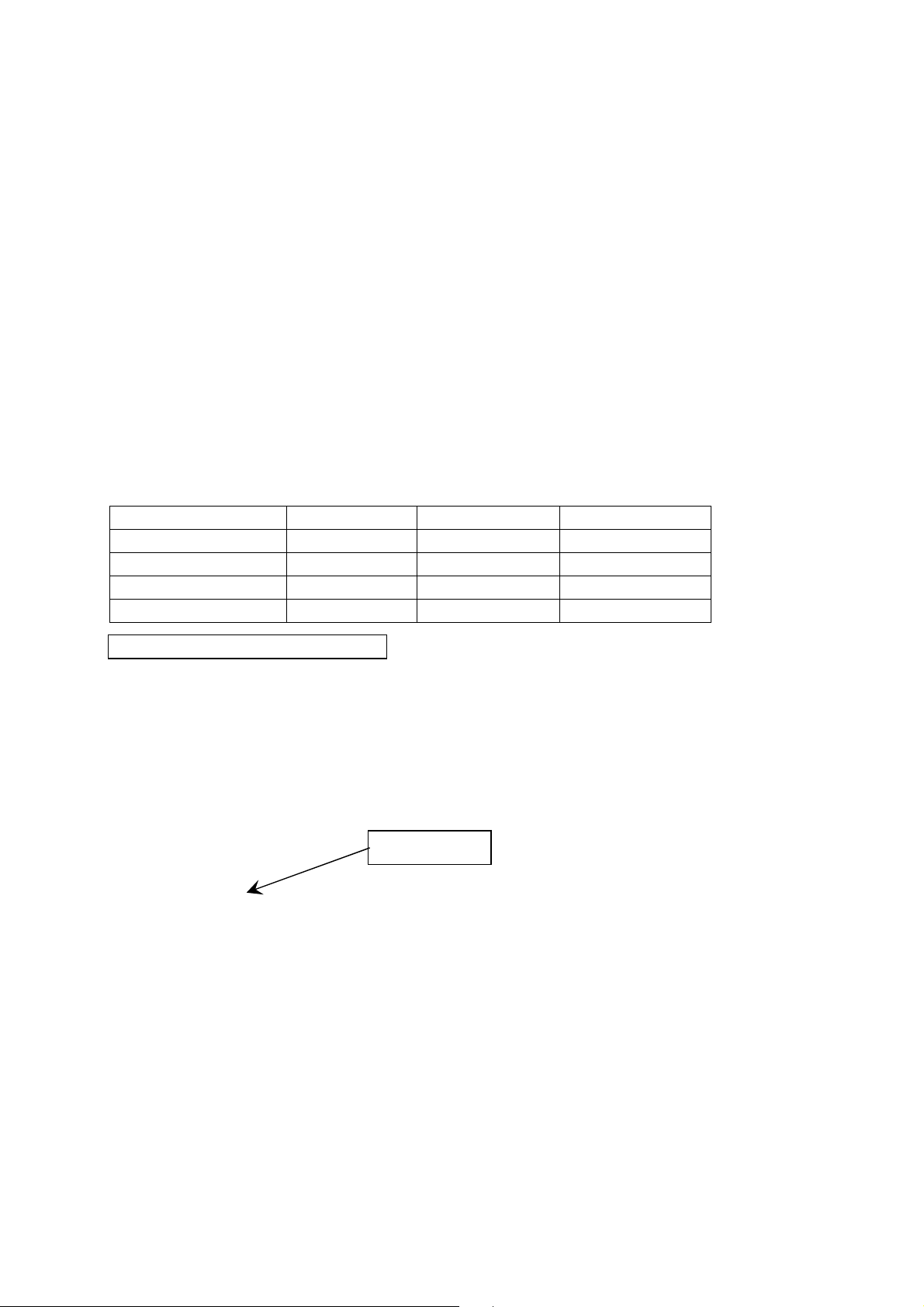
20 Adjusting dimension
For the pumps of the series EC 25 / EC 40 / EC 60
Laminum-Ring
Pump type Adjusting dimension X
EC 25
EC 40
53.00 mm ±0.05
2.087” ±.002
74.90 mm ±0.05
2.949” ±.002
EC 60
Remeasure the adjusting dimension X.
If this dimension is not correct, install a new Laminum ring and measure the
adjusting dimension once again. Then peel off the layer(s) by the difference
so that the necessary adjusting dimension is achieved.
One layer is 0.05 mm or .002” thick.
120.75 mm ±0.05
4.754” ±.002
Revision 4.4 / November 2010 15
Page 16

21 Tightening torques
WATSON-MARLOW MASOSINE PUMP EC 25
Flange - Bearing Housing M6 DIN 7984
Flange - Pump Housing M8 DIN 931
Adapter Plate - Pump Housing M8 DIN 933
Shaft Nut - Pump Shaft
RIGHT-HAND THREAD
SW30
Cap Nut / Wing Nut - Pump Housing SW 22
Oil Plug - Bearing Housing R ¼“ DIN 910
WATSON-MARLOW MASOSINE PUMP EC 40
Flange - Bearing Housing M8 DIN 7984
Flange - Pump Housing M10 DIN 933
10 N•m
7 lb•ft
25 N•m
18 lb•ft
25 N•m
18 lb•ft
80 N•m
59 lb•ft
45 Nm / 19 N•m
33 / 14 lb•ft
10 N•m
7 lb•ft
25 N•m
18 lb•ft
50 N•m
37 lb•ft
Adapter Plate - Pump Housing M8 DIN 933
Shaft Nut - Pump Shaft
RIGHT-HAND THREAD
SW 38
Cap Nut / Wing Nut - Pump Housing SW 22
Oil plug - Bearing Housing R ¼“ DIN 910
WATSON-MARLOW MASOSINE PUMP EC 60
Flange - Bearing Housing M12 DIN 7984
Flange - Pump Housing M12 DIN 933
Adapter plate - Pump Housing M8 DIN 933
Shaft Nut - Pump Shaft
RIGHT-HAND THREAD
SW 50
25 N•m
18 lb•ft
108 N•m
80 lb•ft
45 Nm / 19 N•m
33 / 14 lb•ft
10 N•m
7 lb•ft
90 N•m
66 lb•ft
90 N•m
66 lb•ft
25 N•m
18 lb•ft
135 N•m
100 lb•ft
Cap Nut / Wing Nut - Pump Housing SW 22
33 / 25 lb•ft
10 N•m
45 Nm / 34 N•m
Oil Plug - Bearing Housing R ¼“ DIN 910
Revision 4.4 / November 2010 16
7 lb•ft
Page 17

22 Dismantling
Remove the Front Cover to the front
Before the work starts, the shaft has to be fixed
against movement
Remove Cap Nuts / Wing Nuts (RIGHT-HAND thread)
Remove the Liner, front
Compare the tool kit illustration
Revision 4.4 / November 2010 17
Page 18

Loosen and remove the Shaft Nut
Remove the Rotor-Assembly, consisting of Rotor,
Scraper and Guide Rail
Revision 4.4 / November 2010 18
Page 19

23 Dismantling „Lip Seal System“
The Liner, back consists of the Lip Seal System
The nose of the tool has to be hooked in the
groove of the Liner
Remove the Shaft Sleeve
Take off the Lip Seals and Lip Seal Support
Rings for exchanging
Remove the Liner, back with the aid of tool kit
Revision 4.4 / November 2010 19
Page 20

Face, static
24 Dismantling „Mechanical Seal System“
The Liner, back consists of the Mechanical Seal
System
The nose of the tool has to be hooked in the
groove of the Liner
Remove the Dynamic Ring Holder together with
Face, dynamic
Remove the Liner, back with aid of tool kit
Revision 4.4 / November 2010 20
Remove carefully the Face, static
Page 21

25 Assembly
The assembly has to be done in the same instruction order as the disassembly.
25.1 Assembly „Rotor-Assembly“
During mounting of the
Rotor-Assembly the noses of
the Guide rail mustn’t be
laid on the surface of the
Rotor. To achieve this you
have to fit Scraper and
Guide rail in a position that
the noses of the Guide rail
are touching the gable end
of the Rotor.
After that you have to put the
assembly unit non-violently
into the Liner.
Revision 4.4 / November 2010 21
Page 22

26 Pump sizes
26.1 Cross section drawing EC 25 with Lip Seal System
26.2 Cross section drawing EC 25 Mechanical Seal System
Revision 4.4 / November 2010 22
Page 23

26.3 Cross section drawing EC 40 with Lip Seal System
26.4 Cross section drawing EC 40 with Mechanical Seal System
Revision 4.4 / November 2010 23
Page 24

26.5 Cross section drawing EC 60 with Lip Seal System
26.6 Cross section drawing EC 60 with Mechanical Seal System
Revision 4.4 / November 2010 24
Page 25

26.7 Parts list for an EC 25 / EC 40 / EC 60 Pump
No. Qty. Item Description No. Qty. Item Description
1 3 XX-1610-ZZ Cap Nut EC 25 14 1 XX-1400-ZZ Bearing Housing
1 XX-1600-ZZ Wing Nut EC 25 15 1 XX-3101-ZZ Lip Seal, Outboard
1 6 XX-1610-ZZ Cap Nut EC 40 16 1 XX-3702-ZZ Shaft Key
1 XX-1600-ZZ Wing Nut EC 40 17 1 XX-1000-ZZ Shaft
1 10 XX-1610-ZZ Cap Nut EC 60 18 1 XX-2800-ZZ Bearing Lock Nut
1 XX-1600-ZZ Wing Nut EC 60 19 1 XX-3703-ZZ Tabwasher
2 3 XX-1800-ZZ Front Cover Stud EC 25 20 1 XX-3704-ZZ Drain Plug
2 6 XX-1800-ZZ Front Cover Stud 40 21 2 XX-2600-ZZ Tapered Roller Bearing
2 10 XX-1800-ZZ Front Cover Stud EC 60 22 1 XX-8000-ZZ Mounting Plate
3 2 XX-3000-ZZ O-Ring, Rotor 24 1 XX-1401-ZZ Shims
4 1 XX-0300-ZZ Pump Housing 25 4 XX-3705-ZZ Safety Pin
5 1 XX-0100-ZZ Rotor 28 1 XX-1200-ZZ Liner, back
7 1 XX-3001-ZZ O-Ring, Bearing Housing 29 2 XX-3002-ZZ O-Ring, Liner
8 1 XX-1300-ZZ Flange 30 1 XX-3707-ZZ Bearing Housing Cap Screw
9 8 XX-3200-ZZ Housing Mounting Bolt 32 1 XX-1250-ZZ Liner, front
10 4 XX-3201-ZZ Cap Screw, Bearing Housing 33 1 XX-0200-ZZ Front Cover
11 1 XX-3700-ZZ Snap Ring EC 25 / EC 40 34 1 XX-0800-ZZ Shaft Nut
11 1 XX-3700-ZZ Snap Ring EC 40 35 1 XX-0400-ZZ Scrapergate
12 1 XX-3103-ZZ Lip Seal, inboard 36 1 XX-0700-ZZ Guide Rail
13 1 XX-3701-ZZ Vent Valve
47 1 25-3800-ZZ Oil Sight Glass
26.8 Parts list for the Lip Seal System EC 25 / EC 40 / EC 60
6 2 XX-3102-ZZ Lip Seal EC 25 27 1 XX-3708-ZZ Lip Seal Support Ring EC 25
6 3 XX-3102-ZZ Lip Seal EC 40 / EC 60 27 2 XX-3708-ZZ Lip Seal Support Ring EC 40
23 1 XX-3103-ZZ Lip Seal EC 25
26 1 XX-3706-ZZ Spacer Ring EC 25
27 2 XX-3708-ZZ Lip Seal Support Ring EC 60
31 1 XX-0610-ZZ Shaft Sleeve, Lip Seal
26.9 Parts list for the Mechanical Seal System EC 25 / EC 40 / EC 60
No. Qty. Item Description No. Qty. Item Description
31 1 XX-3611-ZZ Dynamic Ring Holder 42 4 XX-3606-ZZ Set Screw EC 40 / EC 60
37 1 XX-3601-ZZ Face dyn. 43 1 XX-3607-ZZ Static Ring Holder
38 1 XX-3602-ZZ Face stat. 44 1 XX-3608-ZZ Snap Ring
39 1 XX-3603-ZZ O-Ring, Face static 45 1 XX-3609-ZZ Spring Retainer Ring
40 1 XX-3604-ZZ O-Ring, Static Ring Holder 46 6 XX-3610-ZZ Spring EC 25
41 1 XX-3605-ZZ Spring Spacer 46 8 XX-3610-ZZ Spring EC 40 / EC 60
42 3 XX-3606-ZZ Set Screw EC 25
Please ensure you quote the Type when ordering spare parts!
(See technical data sheet)
Revision 4.4 / November 2010 25
Page 26

27 Code-Structure for spare part orders
Structure of the article number:
xx-yyyy-zz
Type of pump Part number Code of material
. Type of pump
1
code pump size
E25 EC 25
E60 EC 60
E40 EC 40
2. Part numbers: Please see attached technical data sheet.
3. Code of material
a. Elastomer
b. Plastics
c. Carbide / Carbon
Code Material Code Material
80 NBR / BUNA 82 EPDM
84 VITON 88 PTFE
86 Silicone
Code Material
49 MASOTRONIC-2070-WR
50 MASOTRONIC-2800-PO or MASOTRONIC-2810-PO
53 MASOTRONIC-2050-UH
62 MASOTRONIC-2080-PK
Code Material Code Material
40 ceramic 41 silicon carbide
66 carbon
Revision 4.4 / November 2010 26
Page 27

28 Dimensional drawings
28.1 Dimension table for pump with German Milk Fittings
EC 25
mm 235 290 35 339 185 155 15 52 88 32,2 NW 65
EC 40
mm 296 382 35 431 200 170 20 50 130 30.2 NW 100
EC 60
mm 463 602 54 654 315 285 20 82 150 56,2 NW 150
EC 25
mm 118,5 160 278 125 140 23 28 17 60,2 Ø 9 NW 65
EC 40
mm 173 220 393 255 270 25,5 38 22 97,4 Ø 9 NW 100
EC 60
mm 234 315 549 315 330 25,5 50 28,5 146,8 Ø 9 NW 150
IN 9.25 11.42 1.38 13.35 7.28 6.11 0.59 2.05 3.46 1.27 NW 65
IN 11.65 15.04 1.38 16.97 7.87 6.69 0.79 1.97 5.12 1.19 NW 100
IN 18.23 23.71 2.13 25.75 12.41 11.22 0.79 3.22 5.91 2.21 NW 150
IN 4.67 6.3 10.94 4.92 5.51 0.91 1.1 0.67 2.37 0.36 NW 65
IN 6.81 8.66 15.47 10.04 10.63 1 1.5 0.87 3.83 0.36 NW 100
IN 9.21 12.4 21.61 12.41 12.99 1 1.97 1.12 5.78 0.36 NW 150
A B C D E F G H I K Fittings
L M P R S T U V W X Fittings
Revision 4.4 / November 2010 27
Page 28

28.2 Dimension table for pump with TRI-CLAMP (TC)
EC 25
mm 235 290 35 339 185 155 15 52 88 32,2 TC 2,5"
EC 40
mm 296 382 35 431 200 170 20 50 130 30,2 TC 4"
EC 60
mm 463 602 54 654 315 285 20 82 150 56,2 TC 6"
EC 25
mm 118,5 133 251 125 140 23 28 17 60,2 Ø 9 TC 2,5"
EC 40
mm 173 179 352 255 270 25,5 38 22 97,4 Ø 9 TC 4"
EC 60
mm 234 295 530 315 330 25,5 50 28,5 146,8 Ø 9 TC 6"
IN 9.25 11.42 1.38 13.35 7.28 6.11 0.59 2.05 3.46 1.27 TC 2,5"
IN 11.65 15.04 1.38 16.97 7.87 6.69 0.79 1.97 5.12 1.19 TC 4"
IN 18.23 23.71 2.13 25.75 12.41 11.22 0.79 3.22 5.91 2.21 TC 6"
IN 4.67 5.22 9.88 4.92 5.51 0.91 1.1 0.67 2.37 0.36 TC 2,5"
IN 6.81 7.04 13.86 10.04 10.63 1 1.5 0.87 3.83 0.36 TC 4"
IN 9.21 11.61 20.86 12.41 12.99 1 1.97 1.12 5.78 0.36 TC 6"
A B C D E F G H I K Fittings
L M P R S T U V W X Fittings
28.3 Dimension table for pump with RJT
EC 25
mm 235 290 35 339 185 155 15 52 88 32,2 RJT 2,5"
EC 40
mm 296 382 35 431 200 170 20 50 130 30,2 RJT 4"
EC 25
mm 118,5 146 264 125 140 23 28 17 60,2 Ø 9 RJT 2,5"
EC 40
mm 173 192 365 255 270 25,5 38 22 97,4 Ø 9 RJT 4"
IN 9.25 11.42 1.38 13.35 7.28 6.11 0.59 2.05 3.46 1.27 RJT 2,5"
IN 11.65 15.04 1.38 16.97 7.87 6.69 0.79 1.97 5.12 1.19 RJT 4"
IN 4.67 5.75 10.39 4.92 5.51 0.91 1.1 0.67 2.37 0.36 RJT 2,5"
IN 6.81 7.56 14.37 10.04 10.63 1 1.5 0.87 3.83 0.36 RJT 4"
A B C D E F G H I K Fittings
L M P R S T U V W X Fittings
28.4 Dimension table for pump with SMS (Swedish norm)
EC 25
mm 235 290 35 339 185 155 15 52 88 32,2 SMS 2,5"
EC 40
mm 296 382 35 431 200 170 20 50 130 30,2 SMS 4"
EC 25
mm 118,5 144 262 125 140 23 28 17 60,2 Ø 9 SMS 2,5"
EC 40
mm 173 201 374 255 270 25,5 38 22 97,4 Ø 9 SMS 4"
IN 9.25 11.42 1.38 13.35 7.28 6.11 0.59 2.05 3.46 1.27 SMS 2,5"
IN 11.65 15.04 1.38 16.97 7.87 6.69 0.79 1.97 5.12 1.19 SMS 4"
IN 4.67 5.67 10.31 4.92 5.51 0.91 1.1 0.67 2.37 0.36 SMS 2,5"
IN 6.81 7.91 14.72 10.04 10.63 1 1.5 0.87 3.83 0.36 SMS 4"
A B C D E F G H I K Fittings
L M P R S T U V W Z Fittings
28.5 Dimension table for pump with SMS (French norm)
EC 25
mm 235 290 35 339 185 155 15 52 88 32,2 SMS 2,5"
EC 40
mm 296 382 35 431 200 170 20 50 130 30,2 SMS 4"
EC 25
mm 118,5 144 262 125 140 23 28 17 60,2 Ø 9 SMS 2,5"
EC 40
mm 173 196 369 255 270 25,5 38 22 97,4 Ø 9 SMS 4"
IN 9.25 11.42 1.38 13.35 7.28 6.11 0.59 2.05 3.46 1.27 SMS 2,5"
IN 11.65 15.04 1.38 16.97 7.87 6.69 0.79 1.97 5.12 1.19 SMS 4"
IN 4.67 5.67 10.31 4.92 5.51 0.91 1.1 0.67 2.37 0.36 SMS 2,5"
IN 6.81 7.72 14.52 10.04 10.63 1 1.5 0.87 3.83 0.36 SMS 4"
A B C D E F G H I K Fittings
L M P R S T U V W X Fittings
Revision 4.4 / November 2010 28
 Loading...