


GKD46TIMASZO
Installation instructions
Induction hob with integrated range hood
GKD46TIMASZO - Fusion
1039697-R02
06/09/2018
1039697-R02
1
The appliance should be installed by qualified personnel only. Each step must be carried out and checked in full in
the order specified.
Validity
Model designation Model number Type
Fusion 31094 GKD46TIMASZO
Identification plate
The identification plate is located next to the connection plate.
▸ Affix the second identification plate (supplied) in an access-
ible position behind the front of the fitted cabinet beneath
the appliance.
Identification plate
Connection plate
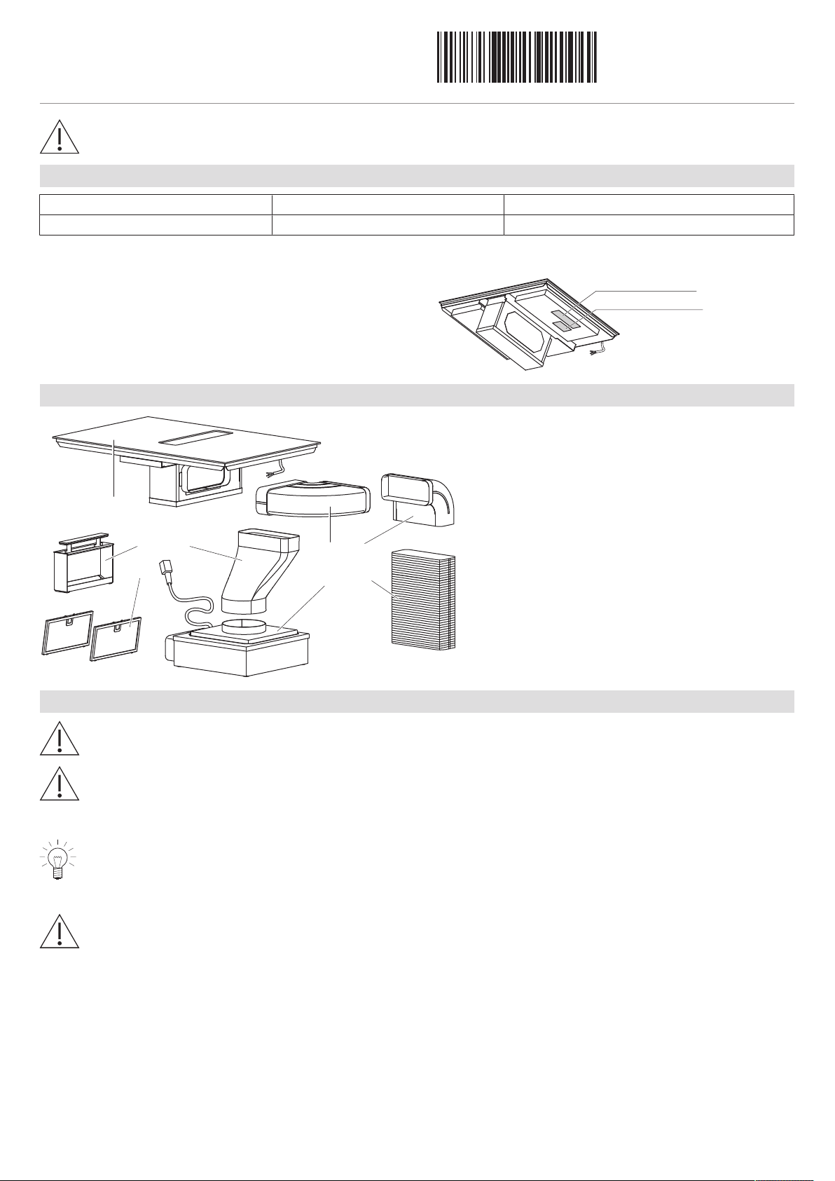
Scope of delivery
H
G
D
F
E
A
B
C
A Hob
B Filter cassette
C 2x grease filter
D Elbow 90°, horizontal
E Elbow 90°, vertical
F Flat channel, flexible
G Offsetting end piece
H Fan motor
General notes
If installing into a combustible material, the guidelines and standards for low-voltage installations and fire protection
must be strictly observed.
If other firing systems are being used at the same time (e.g. wood, gas, oil or coal fired heating appliances), safe op-
eration is only possible providing a room negative pressure of 4 Pa (0.04 mbar) is not exceeded at the location of the
appliance. Risk of toxic fumes! An adequate flow of fresh air must be guaranteed e.g. via non-closable openings in
doors or windows and in combination with an air-intake/exhaust-air wall box or by other technical means.
Efficient repairs can only be guaranteed if it is possible to disconnect the complete appliance at any time without
causing any damage.
Extraction mode
The extracted air must not be fed into a chimney which is used for exhausting fumes from appliances burning gas or
other fuels. Observe the local fire regulations.
Installation instructions
Induction hob with integrated range hood
GKD46TIMASZO - Fusion
1039697-R02
06/09/2018
1039697-R02
2
Recirculation mode
The ventilation outlet must not be covered during operation.
Dedicated accessories that need to be fitted to operate the appliance in the recirculation mode: 1012161 recirculation
box with activated charcoal filters!
▪ Install the recirculation box with activated charcoal filter in the base or adjacent cabinet.
▪ If the recirculation box is not equipped with activated charcoal filters, these have to be ordered and installed before using the appli-
ance for the first time.
Installation accessories supplied
Designation Art. no.
Aluminium tape H42067
Flush installation:
Designation Art. no.
Cementing-in instructions J004133
Sealing strip set H63283
Spacer set H60330
Accessories
Flush installation:
Designation Art. no.
Steel angle set, installation dimension 80 H63774
Instant adhesive for installation of the steel angle (50 ml) B11657
Straight mixing nozzle B11656
TREMCLEAN isopropyl alcohol (1000 ml) 1056609
Black silicone FA880 (310 ml) B11555
Anthracite silicone FA880 (310 ml) B11556
White silicone FA880 (310 ml) 1031313
Stone grey silicone FA880 (310 ml) 1031314
Marble smoothing agent AA320 (1000 ml) B11557
Fugenboy (silicone finishing tool) B75158
Electrical connection
Electrical connections must be carried out by qualified personnel in accordance with the guidelines and standards
for low-voltage installations and the specifications of the local electricity supply companies.
Refer to the identification plate for information on the required mains voltage, current type and fuse protection.
A plug-in appliance may only be connected to a socket outlet with earthing contact, installed according to specifications. An
all-pole mains isolating device with 3 mm contact opening should be provided in the house wiring system. Switches, plug and
socket devices, circuit breakers and fusible cut-outs which are accessible after installation and which have all-poles switching
are permissible as isolating devices. Effective earthing and separately installed neutral and earth conductors ensure safe and
fault-free operation. After installation, live parts and cables with basic insulation must not be accessible. Check old installa-
tions.
▸ If the hobs are used at an altitude of over 2,000 meters above sea level, a reduced performance must be expected.
Installation instructions
Induction hob with integrated range hood
GKD46TIMASZO - Fusion
1039697-R02
06/09/2018
1039697-R02
3
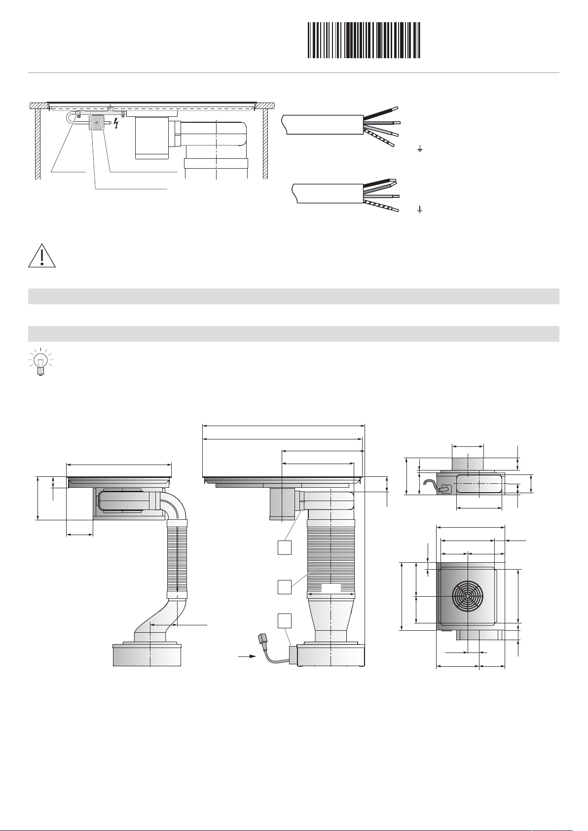
The appliance is equipped with a connection cable which must be connected to an on-site junction box.
Installation pipe
Distribution box
Clamp
brown + black
blue
yellow/green
black
blue
yellow/green
brown
L2
L1
N
N
L1
PE/
PE/
400 V 2N~ / 16 A
230 V~ / 32 A
Error message U400
Faulty connection:
A pole conductor has been connected to the connection terminal for neutral conductors.
Quickly disconnect the appliance from the mains!
Ventilation
There must be a sufficient supply of fresh air in order to ensure good ventilation.
Dimensions
All plastering, plasterboarding, wall papering or painting work is to be carried out prior to installing the appliance.
Ensure that the material is sufficiently stable.
Plan a removable base plate or service flap for fan motor (and recirculation box in the case of the recirculation
mode).
For the recirculation mode, ensure sufficient ventilation so that moisture can escape. Plan in suitable material/wood.
225
778
73
398
347
761
501
126
206
222
ø146
89
176
108
X
X
52
60
129.5
333
188
256 60
(145)
330
165
37
(165)
(203.5)
58.5
256
56
53
8
129.5
1.
3.
2.
1. The exhaust ducting can be to the left or right.
2. The fan motor can be turned, this changes the installation type.
3. Depending on space requirements, the position of the fan motor can be adjusted by shortening the flat channel.
Installation instructions
Induction hob with integrated range hood
GKD46TIMASZO - Fusion
1039697-R02
06/09/2018
1039697-R02
4
General information about installation
▪ The worktop must be flat in order that it is sufficiently sealed against the ingress of liquids.
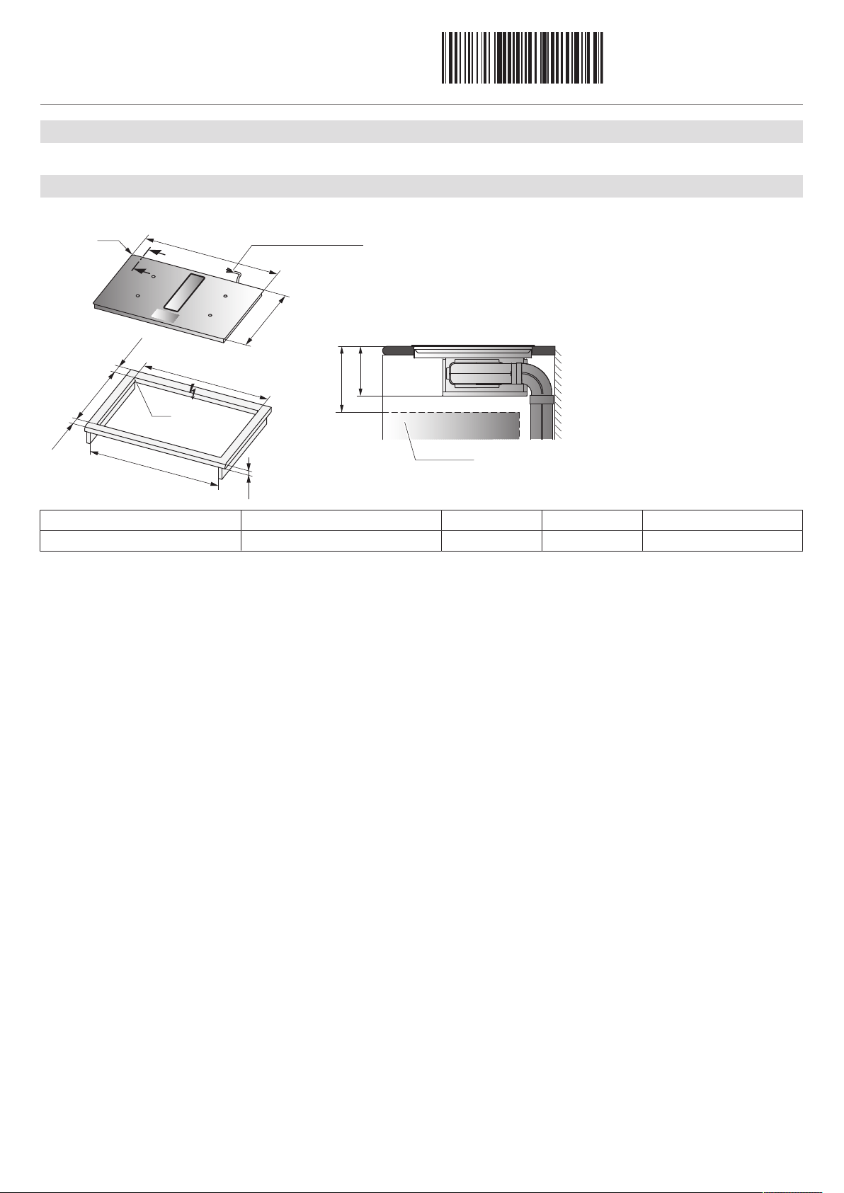
Surface-mounted installation
The layout of the hob to be fitted may differ from the hob illustrated!
Y – Y
Drawer
Cable length 1.7 m
B
H
501
Ri
761
Y
Y
490±1
≥50
A
≥50
Ra
7
50±1
82
5/900
Type A Depends on producer B H Corner radius Ra/Ri
GKD46TIMASZO 20–70mm ≥212mm 202mm 5/1.5mm
A Worktop depth
B Required clearance for service replacement over the entire cut-out area.
H Dimension from the top of the work surface to the underside of the hob
Ri Corner radii of appliance Ra Outer corner radii of cut-out
W The intermediate base must be removable from below.
Installation
1. Create the mounting cut-out accurately.
2. Carefully place the appliance in the mounting cut-out and push against the work surface until flat.
 Loading...