


E 1
IMPORTANT SAFETY INSTRUCTIONS
•Read these instructions.
•Keep these instructions.
•Heed all warnings.
•Follow all instructions.
•Do not use this apparatus near water.
•Mains powered apparatus shall not be exposed to dripping or splashing and that no objects filled with liquids, such as vases, shall be placed on the apparatus.
•Clean only with dry cloth.
•Do not block any ventilation openings. Install in accordance with the manufacturer's instructions.
•Do not install near any heat sources such as radiators, heat registers, stoves, or other apparatus (including amplifiers) that produce heat.
•Do not defeat the safety purpose of the polarized or grounding-type plug. A polarized plug has two blades with one wider than the other. A grounding type plug has two blades and a third grounding prong. The wide blade or the third prong are provided for your safety. If the provided plug does not fit into your outlet, consult an electrician for replacement of the obsolete outlet. (for USA and Canada)
•Protect the power cord from being walked on or pinched particularly at plugs, convenience receptacles, and the point where they exit from the apparatus.
•Only use attachments/accessories specified by the manufacturer.
•Unplug this apparatus during lightning storms or when unused for long periods of time.
•Turning off the power switch does not completely isolate this product from the power line so remove the plug from the socket if not using it for extended periods of time.
•Install this product near the wall socket and keep the power plug easily accessible.
•WARNING—This apparatus shall be connected to a mains socket outlet with a protective earthing connection.
•Refer all servicing to qualified service personnel. Servicing is required when the apparatus has been damaged in any way, such as power-supply cord or plug is damaged, liquid has been spilled or objects have fallen into the apparatus, the apparatus has been exposed to rain or moisture, does not operate normally, or has been dropped.
•Do not install this equipment on the far position from wall outlet and/ or convenience receptacle.
•Do not install this equipment in a confined space such as a box for the conveyance or similar unit.
•Excessive sound pressure from earphones and headphones can cause hearing loss.
•Use only with the cart, stand, tripod, bracket, or table specified by the manufacturer, or sold with the apparatus. When a cart is used, use caution when moving the cart/apparatus combination to avoid injury from tip-over.
The lightning flash with arrowhead symbol within an equilateral triangle, is intended to alert the user to the presence of uninsulated "dangerous voltage" within the product's enclosure that may be of sufficient magnitude to constitute a risk of electric shock to persons.
The exclamation point within an equilateral triangle is intended to alert the user to the presence of important operating and maintenance (servicing) instructions in the literature accompanying the product.
CAUTION
Danger of explosion if battery is incorrectly replaced. Replace only with the same or equivalent type.
THE FCC REGULATION WARNING (for USA)
This equipment has been tested and found to comply with the limits for a Class B digital device, pursuant to Part 15 of the FCC Rules.These limits are designed to provide reasonable protection against harmful interference in a residential installation.This equipment generates, uses, and can radiate radio frequency energy and, if not installed and used in accordance with the instructions, may cause harmful interference to radio communications. However, there is no guarantee that interference will not occur in a particular installation. If this equipment does cause harmful interference to radio or television reception, which can be determined by turning the equipment off and on, the user is encouraged to try to correct the interference by one or more of the following measures:
•Reorient or relocate the receiving antenna.
•Increase the separation between the equipment and receiver.
•Connect the equipment into an outlet on a circuit different from that to which the receiver is connected.
•Consult the dealer or an experienced radio/TV technician for help.
Unauthorized changes or modification to this system can void the user’s authority to operate this equipment.
Notice regarding disposal (for EU)
If this “crossed-out wheeled bin” symbol is shown on the product or in the operating manual, you must dispose of the product in an appropriate way. Do not dispose of this product along with your household trash. By disposing of this product correctly, you can avoid
environmental harm or health risk.The correct method of disposal will depend on your locality, so please contact the appropriate local authorities for details.
*All product names and company names are the trademarks or registered trademarks of their respective owners.

Table of Contents |
|
Introduction ......................................................................... |
4 |
Welcome! ........................................................................................................ |
4 |
Main features .................................................................................................. |
4 |
Signal path ...................................................................................................... |
5 |
What is Valve Reactor technology? ................................................................ |
5 |
Quick start .......................................................................... |
6 |
Setup .............................................................................................................. |
6 |
Checking out the preset programs .................................................................. |
7 |
Switching between the user programs ............................................................ |
7 |
Top and rear panels ............................................................. |
8 |
A. Top panel .................................................................................................... |
8 |
B. Rear panel ................................................................................................ |
11 |
About the three operating modes........................................ |
12 |
Preset mode (recalling preset programs) ..................................................... |
12 |
Manual mode ................................................................................................ |
12 |
Channel Select mode (recalling user programs) .......................................... |
13 |
Creating and saving sounds ............................................... |
14 |
Creating a sound .......................................................................................... |
14 |
Adjusting the noise reduction ....................................................................... |
15 |
Saving a program ......................................................................................... |
15 |
Checking the original values saved in a program ......................................... |
16 |
Restoring the factory settings ....................................................................... |
16 |
Using a foot switch (VOX VFS5) .......................................... |
17 |
Foot switch operations in Channel Select mode ........................................... |
17 |
Foot switch operations in Preset or Manual modes ...................................... |
17 |
Explanation of the amps and effects.................................... |
18 |
Amp models .................................................................................................. |
18 |
Effects ........................................................................................................... |
21 |
Reverb .......................................................................................................... |
23 |
Troubleshooting ................................................................. |
24 |
Specifications .................................................................... |
25 |
Song program list .............................................................. |
26 |
Program sheet ................................................................... |
27 |
3

Introduction
Welcome!
Thank you for purchasing the VOX VT15 or VT30 Valvetronix amp.
To help you get the most out of your new amplifire, please read this manual carefully.
Get ready to enjoy the VT15/30’s amazing guitar sounds!
Main features
The VT15 and VT30 use Valve Reactor technology, and feature a power amp circuit containing a 12AX7 (ECC83) dual triode valve (“vacuum tube”) that would normally be used in a preamp. This allows the amp to produce the true sound and feel of a bona fide all valve (tube) amp.
Sophisticated modeling technology is used to provide twenty-two different amps.
Twelve high-quality effects are built-in. Of these, reverb is available at all times, and three of the remaining eleven effects are “multiple effects” that allow you to use up to three effects simultaneously. Noise reduction can also be used simultaneously.
You can create a sound using the desired amp and effect, and save it in memory as one of eight programs (two banks x four channels). Programs can be switched while you perform, either from the top panel or from a foot switch connected to the rear panel (Channel Select mode). For each amp model, three preset programs – Basic Effected, and Song – are provided, giving you a total of 66 programs (Preset mode). The song programs reproduce the tones of classic hits played by famous guitarists.
Manual mode lets you use the VT15/30 as a conventional guitar amp. The physical positions of the actual knobs will be reflected by the sound.
An optional VOX VFS5 foot switch (sold separately) can be connected, allowing you to switch programs or turn effects on/off with your feet.
The power level control lets you adjust the output wattage of the power amp. Even with the master volume set to the maximum so that the Valve Reactor power amp is loaded, you’ll still be able to adjust the volume without impairing the tonal character.
4
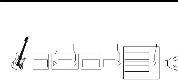
Signal path
Your guitar sound passes through the following sections.
Refer to “Top and rear panels” (p.8) in conjunction with this illustration.
|
GAIN |
VOLUME |
|
MASTER |
POWER LEVEL |
|
|
|
|
|
VALVE REACTOR |
|
|
|
|
|
VALVE |
EFFECT |
PRE AMP |
EFFECT |
|
ECC83 (12AX7) |
|
COMP |
Select one |
MODULATION |
REVERB |
CLASS A or AB |
|
/OCTAVE |
of 22 |
/DELAY |
|||
|
|
FEEDBACK CIRCUIT
Circuit is determined by Pre Amp selection
VT15/30 Signal route
What is Valve Reactor technology?
The Valve Reactor circuit used in the power amp of this VT15/30 combo amp is based on new technology. Most of the sound creation and tonal shaping is performed in the digital domain, but the Valve Reactor power amp is 100% analog. Passing the guitar signal through the analog-domain power amp stage is an important factor in capturing the feel and tone of the original amp for that model.
Valve Reactor’s power stage is a miniature version of a true tube push/pull power amp. It uses a 12AX7 tube (dual triode; in other words, two vacuum tubes in one), and is similar to a true tube amp with an output transformer. Rather than connecting the vacuum tube directly to a speaker via an output transformer, the signal is converted by a virtual output transformer in which solid stage components emulate the output transformer, and the final output stage circuit is connected to a specially designed VariAmp power circuit. This allows the output of the power stage to be continuously varied from minimum output to maximum output.
This VariAmp power circuit is completely transparent – i.e., it does not modify the signal – so the output tone will be the pure sound of a tube amp. The wide dynamic range seen in a conventional tube amp is also maintained. This dynamic range is a characteristic that is difficult to obtain from a solid-state amp; this is why a tube amp sounds more powerful than a solid-stage amp of the same output specifications. The output of the Valve Reactor power amp “reads” the constantly changing impedance curve of the connected speaker system, and feeds this information back to the vacuum tube. In response to this information, the operation of the amp’s tube stage will vary according to the speaker load (impedance). This too is an important element in the sound of a true tube amp. In addition to producing lively tube sound, “circuitry characteristics” distinctive of the full-tube power stage in the amp being modeled can also be simulated. These characteristics include class-A, class-AB, and power output. By adjusting these characteristics (except for the power output, which the user specifies), every sound of that amp model can be faithfully reproduced. This power amp technology, for which a U.S. patent has been obtained, is unique to the VOX Valvetronix amps.
5

Quick start
This Quick Start section is for those of you who would like to start using your new amp right away.
This manual contains information that will help you take full advantage of your Valvetronix amp, so be sure to read the rest of it after you’ve read the Quick Start section.
HINT: Illustrations of the top panel and rear panel are provided in “Top and rear panels” (p.8), so refer to them as you try out your amp.
Setup
1.Set the VT15/30’s [MASTER] volume to the minimum level.
2.Connect the included power cable to the rear panel AC power connector, and plug the other end into an AC outlet.
3.Plug the cable connected to your guitar into the top panel INPUT jack.
4.Turn on the [POWER] switch.
5.Slowly raise the [MASTER] volume to adjust the volume.
HINT: The rear panel [POWER LEVEL] control adjusts the output level of the power amp. This lets you adjust the volume while preserving the distortion of the power amp.
NOTE: There may be no sound for several seconds until the vacuum tube warms up. This is not a malfunction.
6

Checking out the preset programs
1.Press the top panel [PRESET] switch.
The PRESET LED will light up(Preset mode).
2.Turn the [AMP] selector to select an amp model.
A preset program for a sound that is typical of each amp model will be recalled, and the GAIN, VOLUME, TREBLE, MIDDLE, BASS, and effect settings will switch automatically.
HINT: The amp models are organized into two banks, each bank containing eleven models (a total of twenty-two). Press the AMP switch to change banks. Each time you press this, the AMP LED will change to green or red, and you’ll alternate between amp banks A and B. Each of the twenty-two amp models has three preset programs (a total of sixty-six programs). In Preset mode, pressing the [PRESET] switch will cycle the PRESET LED between green, orange, and red, switching between preset programs 1 (basic), 2 (effected), and 3 (song).
Each song program reproduces the tone of a hit played by a famous guitarist.
Switching between the user programs
1.Press one of the top panel [CHANNEL] switches ([CH1], [CH2], [CH3], or [CH4]). The LED of the [CHANNEL] switch you pressed will light, and the user program specified for that channel will be recalled (Channel Select mode).
HINT: The user programs are organized into two banks, each bank containing four channels (a total of eight programs). Press the [CHANNELBANK] switch to switch banks. Each time you press it, the BANK LED will change between green and red, switching between channel banks 1 and 2.
HINT: You can store your own favorite sounds in a program. For details, refer to “Saving a program” (p.15).
7
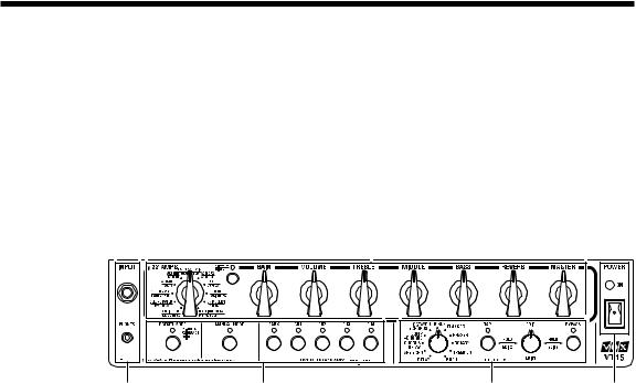
Top and rear panels
In this chapter we're going to take a look at the top and rear panels of your Valvetronix amp.
A.Top panel
2
The illustration shows the VT15.
1 |
4 |
3 |
5 |
1.INPUT/PHONES section
INPUT jack
This is where you plug in your guitar.
PHONES jack
Use this jack if you want to output directly to a mixer or recording device, or when you want to use headphones. The signal that is output from this jack is taken from directly before the Valve Reactor power amp, and the cabinet response of the guitar amp will be applied to it.
NOTE: If you connect this jack, no sound will be output from the internal speaker.
2.Amp section
Here you can make settings for the amp. The “chicken head” type knobs reflect the tradition of VOX amplifiers.
[AMP] switch/selector, LED
Here you can select the amp mode.
Each time you press the [AMP] switch, the AMP LED will change color between green and red, switching between amp banks A and B. Use the [AMP] selector to choose a model within the selected amp bank.
The operation of the pre-amp, power amp (class A or AB), the response of the tone controls and their location within the circuit are all switched according to the amp model you select here, causing each of these to behave as they do in the original amp.
8

In Preset mode (i.e., when the PRESET LED is lit), you can recall preset programs that contain sounds and effect settings that are typical of each amp model.
[GAIN] control
This adjusts the pre-amp gain of the selected amp model.
[VOLUME] control
This adjusts the volume of the selected amp model.
[TREBLE], [MIDDLE], [BASS] controls
These adjust the tone for the high, mid, and low-frequency ranges. The change produced by each control will differ depending on the amp model that you’ve selected.
[REVERB] control
This adjusts the mix amount for the reverb.
[MASTER] volume
This adjusts the volume that is output from the pre-amp to the Valve Reactor power amp. This setting will change the amount of the Valve Reactor’s distortion.
NOTE: The [MASTER] volume setting is not programmed.
NOTE: The amount of Valve Reactor distortion is also affected by the GAIN control. For some settings, there will be almost no distortion.
3.Effect section
Here you can make settings for effects and noise reduction. For details on each effect, refer to “Explanation of the amps and effects” (p.18).
[EFFECTS] selector
This selects the effect type. You can use the [TAP] switch and [EDIT] knob to adjust the parameters of each effect. When you switch the effect type, the parameter settings of the effect will be initialized, and Effect Bypass will be disabled.
[EDIT] knob
This adjusts the parameters of each effect. The knob can adjust three different parameters when used in conjunction with the [TAP] or [BYPASS] switches as described below (when the BYPASS LED is unlit).
-EDIT 1: Turn the [EDIT] knob (without holding down a switch).
-EDIT 2: Turn the [EDIT] knob while holding down the [TAP] switch.
-EDIT 3: Turn the [EDIT] knob while holding down the [BYPASS] switch.
When the BYPASS LED is lit (i.e., when the effect is bypassed), you can adjust the sensitivity of the noise reduction by holding down the [TAP] switch and turning the [EDIT] knob.
NOTE: You can’t adjust effect parameters while the BYPASS LED is lit.
9
 Loading...