


Owner's Manual
E 1

Precautions
Location
Using the unit in the following locations can result in a malfunction.
•In direct sunlight
•Locations of extreme temperature or humidity
•Excessively dusty or dirty locations
•Locations of excessive vibration
•Close to magnetic fields
Power supply
Please connect the designated AC/AC power supply to an AC outlet of the correct voltage. Do not connect it to an AC outlet of voltage other than that for which your unit is intended.
Interference with other electrical devices
Radios and televisions nearby may experience reception interference. Operate this unit at a suitable distance from radios and televisions.
Handling
To avoid breakage, do not apply excessive force to the switches or controls.
Care
If the exterior becomes dirty, wipe it with a clean, dry cloth. Do not use liquid cleaners such as benzene or thinner, cleaning compounds or flammable polishes.
Keep this manual
After reading this manual, please keep it for later reference.
Keeping foreign matter out of your equipment
Never set any container with liquid on this equipment. If liquid gets into the equipment, it could cause a breakdown, fire, or electrical shock.
Be careful not to let metal objects get into the equipment. If something does slip into the equipment, unplug the AC/AC power supply from the wall outlet. Then contact your nearest Korg dealer or the store where the equipment was purchased.
THE FCC REGULATION WARNING (for U.S.A.)
This equipment has been tested and found to comply with the limits for a Class B digital device, pursuant to Part 15 of the FCC Rules. These limits are designed to provide reasonable protection against harmful interference in a residential installation. This equipment generates, uses, and can radiate radio frequency energy and, if not installed and used in accordance with the instructions, may cause harmful interference to radio communications. However, there is no guarantee that interference will not occur in a particular installation. If this equipment does cause harmful interference to radio or television reception, which can be determined by turning the equipment off and on, the user is encouraged to try to correct the interference by one or more of the following measures:
•Reorient or relocate the receiving antenna.
•Increase the separation between the equipment and receiver.
•Connect the equipment into an outlet on a circuit different from that to which the receiver is connected.
•Consult the dealer or an experienced radio/TV technician for help.
Unauthorized changes or modification to this system can void the user’s authority to operate this equipment.
ii

CE mark for European Harmonized Standards
CE mark which is attached to our company’s products of AC mains operated apparatus until December 31, 1996 means it conforms to EMC Directive (89/336/EEC) and CE mark Directive (93/68/EEC). And, CE mark which is attached after January 1, 1997 means it conforms to EMC Directive (89/336/ EEC), CE mark Directive (93/68/EEC) and Low Voltage Directive (73/23/EEC).
Also, CE mark which is attached to our company’s products of Battery operated apparatus means it conforms to EMC Directive (89/336/EEC) and CE mark Directive (93/68/EEC).
IMPORTANT NOTICE TO CONSUMERS
This product has been manufactured according to strict specifications and voltage requirements that are applicable in the country in which it is intended that this product should be used. If you have purchased this product via the internet, through mail order, and/or via a telephone sale, you must verify that this product is intended to be used in the country in which you reside.
WARNING: Use of this product in any country other than that for which it is intended could be dangerous and could invalidate the manufacturer's or distributor's warranty.
Please also retain your receipt as proof of purchase otherwise your product may be disqualified from the manufacturer's or distributor's warranty.
Data Handling
Incorrect operation or malfunction may cause the contents of memory to be lost, so we recommend that you save important data on a floppy disk or other media source. Please be aware that Korg will accept no responsibility for any damages which may result from loss of data.
*A United States patent has been obtained for Valve Reactor technology. Patents are pending in other countries. (As of March 2003)
*Company names, product names, and names of formats etc. are the trademarks or registered trademarks of their respective owners.
iii

Quick Start
A GUIDE FOR THOSE WHO WANT TO PLAY GUITAR FIRST, AND READ THE MANUAL LATER!
ep, we know. You’d rather be playing guitar than reading this manual. Who Ywouldn’t? I know I would so here’s a “Quick Start” to get you up and run-
ning without delay (pun intended)
First we’ll get started by trying out ToneLabSEs programs and then we’ll explain how to use the various controls and knobs to create your own sounds.
Right. Once you’ve gotten the urge to play out of your system, you should really give this manual a chance - it’s been written by a fellow guitar fanatic and is full of useful tips and info that’ll give you much more detail about ToneLabSE than what’s in the “Quick Start.”
Ok, ok we’re almost done here. I just want to recommend to you that you fold out the inside back cover of this manual. Go ahead, I’ll wait.
Good. The reason you should do this is so you can see the pictures of the Top and Rear panels whilst we talk. There, now plug in and play!!!!
SETUP
1.If you’re connecting ToneLabSE to a mixer or recorder, connect OUTPUT jacks L/MONO and R (11.4) to the input jacks of your mixer or recorder. If you’re listening through headphones, connect your headphones to the PHONES jack (11.5).
If you’re connecting ToneLabSE to a guitar amp(s) connect OUTPUT jacks L/ MONO and R to the input jacks of your guitar amp(s).
NOTE: If you’re connecting ToneLabSE to something that only has a mono input, just use the L/MONO jack.
HINT: Rear panel area 9 (at the end of this manual) shows an illustration of this.
2.Turn the LEVEL knob (11.3) on the rear panel of ToneLabSE all the way to the left (as viewed from the rear), setting the volume to 0.
3.Plug the supplied AC/AC power supply into ToneLabSE’s rear panel AC9V power inlet (10.2), and plug the power supply into an AC wall socket.
4.Plug your guitar into the rear panel INPUT jack (11.1).
5.Before you turn ToneLabSE on, lower the volume of your amp or mixer so you don’t hear any potentially speaker-damaging pops or buzzes. Then turn on the STANDBY switch (10.1) to power up ToneLabSE.
6.If you’ve connected ToneLabSE to a mixer or recorder, press the GLOBAL switch (3.4) to select the OUT SEL menu, and use the value knob [6] or the ▲,
iv

▼ buttons to select “Ln” (LINE). If you’ve connected ToneLabSE to your guitar amp, set this to “AP” (AMP).
7.Turn up the volume controls of your amp or mixer, and ToneLabSE’s rear panel LEVEL knob (11.3) to adjust the volume.
NOTE: You won’t hear sound for several seconds while the valve (a.k.a. “vacuum tube” if you live on the west side of the Atlantic) warms up. This isn’t a malfunction
– it’s a real analogue valve!
LISTEN TO THE PROGRAMS
8.Use the BANK UP, DOWN buttons (6.1) to select a bank 1–24. Notice that the number in the bank display (5.1) blinks and changes.
HINT: ToneLabSE has 96 programs, organized into 24 banks with four programs in each bank (24 x 4 = 96). When shipped from the factory, banks 1–8 contain 32 programs. (The programs in banks 1-8, 9-16 and 17-24 are identical to each other)
Program Select mode lets you select these programs. There’s also an effect ON/ OFF mode that lets you turn individual effects on/off.
HINT: For an illustration, look at 3 “Bank/Program/Channel/Select/Display Section” in the diagram at the end of this manual.
9.Use the program select 1–4 pedals (6.2) to select a program.
The program LED you selected will light, and the number in the bank display will also change and stay lit. Go ahead and play your guitar.
For example if you want to select program 3-1 (bank 3, program 1), press the BANK UP or DOWN pedal to make the bank display read “3,” and then press the program select 1 pedal to make the LED light.
If you’re selecting a program in the same bank, simply press a program select 1–4 pedal. If you want to select a program from a different bank, you’ll need to perform steps 8 and 9 in that order.
NOTE: If you can’t select a program, you’re probably not in Program Select mode. Get back into Program Select mode as described in “Program Select mode” (p.16).
HINT: The preset programs cover an amazing range of sounds; fat hi-gain lead sounds, nostalgic clean sounds that work best with your rhythm (neck) pickup, aggressive modern crunch sounds for heavy riffing with your lead (bridge) pickup, and much more. P.68 has a list of the preset programs.
10.The two expression pedals are assigned to control the most appropriate parameters for each program, such as wah, volume, delay, reverb input level, or other effect parameter. The CONTROL switch is assigned functions such as TAP tempo input of the delay time.
11.By pressing the A/B Ch switch you can instantly switch between 2 sets of amp and cabinet models within each program.
12.By pressing the FX ON/OFF (TUNER) switch you can switch to Effect On/Off mode. Effect On/Off mode lets you switch each effect on/off just like you were using a set of stomp boxes. Program select 1–4 will switch pedal, modulation, delay, and reverb on/off respectively, and the BANK DOWN pedal will bypass the insert effect.
v

SWITCHING EFFECTS ON/OFF
13.The model select buttons will be lit (ON) or dark (OFF) to indicate the on/off state of each effect. If you press a button that is dark or turn the model selector, the effect will turn on and the model select button will blink. If you press a button that is blinking, the effect will turn off and the button will go dark.
CREATE YOUR OWN SOUNDS
14.To adjust the sound of the AMP model, use the AMP selector to select one of the sixteen amp models. Then you can simply adjust the sound pretty much in the same way as if you were really using the actual model of guitar amp you selected.
Adjust the GAIN value knob 1, TREBLE value knob 3, MIDDLE value knob 4, BASS value knob 5, and the VR GAIN value knob 2 (which corresponds to the MASTER) as you like. To get the most accurate vintage tube amp distortion, raise the VR GAIN as high as possible. The CH VOLUME value knob 6 lets you adjust the volume while retaining the overall sound including the distortion produced by the Valve Reactor.
If you press the PRES-NR button, you can then use value knob 3 to adjust PRESENCE and value knob 4 to adjust the NR (Noise Reduction) effect. When you use the AMP MODEL and CABINET MODEL selectors, a different type of guitar amp will appear before your very eyes – or, should we say, ears! ToneLabSE holds in its memory two combinations of amp and cabinet models for each program, and you can use the A/B ch pedal to switch instantly between these.
HINT: P.34 lists recommended combinations of amp and cabinet models but others are fine too.
HINT: If you want to replicate the sound of the original amp, set [VR GAIN] to the maximum setting on vintage-type models that do not have a master volume control (i.e., AC15, AC15TB, AC30, AC30TB, UK BLUES, UK 68P, BLACK 2x12, TWEED 1x12, and TWEED 4x10). For modern-type amps that have a master volume control, adjust [VR GAIN] in the same way that you would on the original amp. When the [VR GAIN] setting is low, preamp-type distortion will occur. As you raise the [VR GAIN] setting, the pre-amp will begin loading the Valve Reactor to cause clipping, and the warmth and distortion of the Valve Reactor will be added.
HINT: For an illustration, look at area 1 in the top panel diagram at the end of this manual.
vi

15.ToneLabSE provides a PEDAL effect that is placed before the amp, and MODULATION, DELAY, and REVERB effects that are placed after the cabinet.
For example if you want use the PEDAL effect TREBLE BOOST, turn the PEDAL selector to select TREBLE BOOST. The PEDAL parameter LED of the edit section will blink, indicating the parameter line (the region listing the parameter names). Also, the LEDs below the value knobs will light, indicating the location of the knobs that you can use to control TREBLE BOOST. Now turn value knobs 1, 2, and 3 to adjust DRIVE, LEVEL, and TONE respectively. You can edit other effects using the same procedure.
HINT: Some effect settings may cause unwanted distortion (if there is such a thing!!). If this happens, lower the CH VOLUME.
HINT: For an illustration, look at area 2 in the top panel diagram at the end of this manual.
vii

Table of Contents |
|
Quick Start................................................................................................... |
iv |
Setup....................................................................................................................... |
iv |
Listen to the Programs............................................................................................. |
v |
Switching effects on/off ........................................................................................... |
vi |
Create your own Sounds ........................................................................................ |
vi |
Introduction ................................................................................................. |
1 |
Main Features .......................................................................................................... |
1 |
Valve Reactor Technology....................................................................................... |
2 |
An overview of ToneLabSE ..................................................................................... |
4 |
Signal Route ..................................................................................................... |
4 |
Modes ............................................................................................................... |
4 |
Amp and effect settings (Edit)........................................................................... |
4 |
Realtime expression and control pedals.......................................................... |
4 |
Saving a program ............................................................................................. |
4 |
MIDI and output destination settings ................................................................ |
4 |
A Guitarist’s Guided Panel Tour ................................................................. |
5 |
The Top Panel ......................................................................................................... |
5 |
Model select section ........................................................................................ |
5 |
Edit section ...................................................................................................... |
7 |
Chain/Global/Rename/Write/Exit/Display section............................................ |
8 |
Control Setup section ...................................................................................... |
9 |
Bank display/Tuner display.............................................................................. |
9 |
Bank/Program/Channel/Select section ............................................................ |
9 |
FX ON/OFF Switch ........................................................................................ |
10 |
Effect control section ..................................................................................... |
10 |
Valve.............................................................................................................. |
10 |
Rear panel ............................................................................................................. |
11 |
Power supply ................................................................................................. |
11 |
Inputs and Outputs ........................................................................................ |
11 |
MIDI ............................................................................................................... |
11 |
Setup........................................................................................................... |
13 |
Output settings....................................................................................................... |
13 |
Basic connections .................................................................................................. |
13 |
Using ToneLabSE with a mixer or recorder ........................................................... |
14 |
Example of connections to a mixer or recorder .............................................. |
14 |
Using ToneLabSE with a guitar amp(s) ................................................................. |
15 |
Example of connection to a guitar amp (or amps) .......................................... |
15 |
Using ToneLabSE with a MIDI device or computer ............................................... |
15 |
Playing ToneLabSE .................................................................................... |
16 |
viii

Program Select mode ............................................................................................ |
16 |
Selecting a program........................................................................................ |
16 |
Effect On/Off mode ................................................................................................ |
16 |
Switching effects on/off................................................................................... |
17 |
A/B Channel Hold ........................................................................................... |
17 |
Activating or deactivating the Key Lock function.................................................... |
18 |
Activating the Key Lock function..................................................................... |
18 |
Deactivating the Key Lock function................................................................. |
18 |
Creating and Storing your own Programs............................................... |
19 |
Creating your own Program ................................................................................... |
19 |
Changing the connection order of the effects (CHAIN).......................................... |
21 |
Naming a program ................................................................................................. |
21 |
Storing a program .................................................................................................. |
22 |
Restoring a setting to its original value (Original Value) ........................................ |
22 |
Explanations of the Amp, Cabinet and Effect Types............................... |
23 |
A. AMP Models ...................................................................................................... |
23 |
B. CABINET Models .............................................................................................. |
32 |
WHAT GOES WITH WHAT? .......................................................................... |
34 |
C. PEDAL Effects................................................................................................... |
35 |
D. MOD (Modulation) effects ................................................................................. |
39 |
E. DELAY effects ................................................................................................... |
45 |
F. REVERB effects ................................................................................................ |
48 |
Tuner (Bypass, Mute)................................................................................. |
51 |
Tuning procedure................................................................................................... |
51 |
Calibrating the tuner............................................................................................... |
52 |
Using the expression pedals..................................................................... |
53 |
Expression pedal settings ...................................................................................... |
53 |
Expression Target Quick Assign..................................................................... |
53 |
Setting the Expression Target ........................................................................ |
54 |
Expression pedal control initialization settings ............................................... |
55 |
Control switch settings ........................................................................................... |
56 |
Switching each effect on/off............................................................................ |
56 |
Using TAP TEMPO to set a parameter........................................................... |
56 |
FACTOR value knob 2 setting ........................................................................ |
56 |
Effect control................................................................................................... |
57 |
Adjusting the sensitivity of the pedals .................................................................... |
57 |
Expression pedal 1 ......................................................................................... |
57 |
Expression pedal 2 ......................................................................................... |
58 |
Control via MIDI ......................................................................................... |
59 |
Connecting a MIDI Device or Computer ................................................................ |
59 |
Setting the MIDI Channel (GLOBAL “MIDI CH”).................................................... |
60 |
ix

Program Change (GLOBAL “PCHG OUT”) ........................................................... |
60 |
Control Change (GLOBAL “CCHG I/O”) ................................................................ |
60 |
Parameter Change (GLOBAL “SYEX OUT”) ......................................................... |
61 |
Backing up and Restoring Program Data (GLOBAL “DUMP CUR,” DUMP ALL”).62 |
|
Backing Up ..................................................................................................... |
62 |
Restoring ........................................................................................................ |
63 |
Restoring the Factory Preset Programs................................................... |
64 |
Troubleshooting ........................................................................................ |
65 |
Specifications............................................................................................. |
67 |
Program list................................................................................................ |
68 |
Index ........................................................................................................... |
69 |
x
Introduction
WELCOME ABOARD!
any thanks for adding the VOX Valvetronix ToneLabSE to your sonic Marsenal. We’re sure it’ll give you countless hours of great guitar tones that
will feel as good as they sound!
To maximize your chances of enjoying a long and happy relationship with your ToneLabSE, please read this manual at least once, and (as they say), “use the product as directed.” Keep the manual for future reference after you’ve read it; you’ll want to re-read it later at some point to pick up cool tips you may have missed the first time around.
MAIN FEATURES
•ToneLabSE features Valve Reactor technology that switches between Class A and Class AB power amp circuits with an actual 12AX7 (ECC 83) miniature triode valve (vacuum tube) to create the sound of an actual tube power amp, delivering the response and tone of classic amps.
•ToneLabSE uses sophisticated modeling technology to create classic amp, cabinet, and effect sounds. You can choose from sixteen amp types that include classic vintage amps and expensive high-end valve amps, and eleven different cabinet types. By combining amp types and cabinet types you can create an amazing range of sounds, many of which have never been heard before.
•Since high-quality effects are built in, ToneLabSE is all you need to create a completely finished sound. Sixteen types of pedal effects are placed before the amp, and after the cabinet are eleven types of modulation, eleven types of delay, and eleven types of reverb. You can choose one type for each effect, and use these four effects simultaneously plus Noise Reduction.
•You can store all of your own amp settings and effect model settings as a “program” in one of 96 program memories. ToneLabSE comes with 32 preset programs for instant gratification.
•Manual Mode lets you use ToneLabSE just like conventional amps and effects. The sound will be exactly as specified by the physical positions of the amp section knobs. In other words...what you see is what you get!
•For convenient tuning, an Auto Chromatic Tuner is built-in.
•There are two expression pedals that you can use as a wah pedal, volume pedal, or to control a variety of effect parameters – a great feature for live performance.
•There’s a Quick Assign function that makes it easy to assign parameters to the expression pedal.
•ToneLabSE provides control switches that let you do things like set the delay time via TAP TEMPO, switch insert effects on/off, or switch the speed of a rotary speaker ... again, must-have features for live performance.
1
Creating Playing Setup Panel Tour Introduction and Storing

•You can use the effect insert jacks to connect an external effect processor or stompbox.
•With MIDI IN and OUT connectors, ToneLabSE gives you plenty of potential for expanding your system.
•ToneLabSE Sound Editor is an editor/librarian software that lets you visually edit ToneLabSE’s numerous parameters, and save and manage programs.
To obtain the “ToneLabSE Sound Editor,” please contact the VOX distributor in your country or download the latest version from:
“http://www.voxamps.co.uk” or “http://www.valvetronix.com/” To find your local Distributor go to: “http://www.voxamps.co.uk/dealers/worldwid.htm”
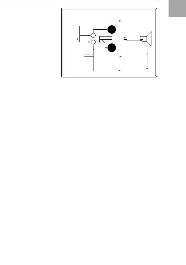
VALVE REACTOR TECHNOLOGY
THE POWER (AMP) AND THE GLORY!
alve Reactor technology was first used on the critically acclaimed VOX VAD60/120VT Valvetronix amps.
The Valve Reactor circuitry in ToneLabSE however has been tuned-up especially for live performance.
Since conventional modeling effects for line recording are not used directly with a speaker, they do not include a power amp circuit, output transformer, or speaker. In other words, they only have a preamp circuit.
A real valve amp sound, however, is produced not just by the preamp, but also by the tone and distortion of the power amp, and by the constant changes in impedance that are created by the power amp driving the speakers. ToneLabSE contains an actual low-wattage valve power amp circuit, a virtual output transformer (patent applied for) that uses solid-state components to simulate an output transformer, and a dummy speaker circuit that simulates the varying impedance of a real speaker. This means that although it’s low-power, ToneLabSE has the same circuit structure of an actual all-valve amp.
While much of the tone creation and shaping carried out is done in the digital domain, its Valve Reactor power amp is 100% analogue. The resulting journey your guitar’s signal takes through the analogue world of the power stage plays a major role in providing the all-important feel and tone of the original amps we modelled. The Valve Reactor power stage is, to all intents and purposes, a bona fide valve (tube) push-pull power amplifier, but in miniature. It utilizes a 12AX7 (ECC83) valve (a dual triode device - meaning “two valves in one”) and is equipped with an output transformer, like a “real” valve amp.
The power amp output of ToneLabSE’s Valve Reactor is designed to “read” the constantly changing impedance curve of the dummy speaker circuit system and feed this information back to the virtual output transformer – just like real valve amplifiers do. This information permits the behavior of the valve stage of the amp to vary with the speaker load (impedance), which is another important part of “real world” valve tone.
2
Apart from the vital |
|
|
|
|
|
|
|
|
|
|
|
|
|
|
|
|
|
|
|
|
|
|
|
|
|
|
VOX VALVE REACTOR |
|
|
|
|||||||||
valve tone this ingenious |
|
|
|
|
|
|
|
|
|
|
|||||||||
power amp design provides, it |
|
|
|
|
|
|
|
|
|
|
|
|
|
|
|
|
|
|
|
|
|
|
|
|
|
|
|
|
|
|
|
|
|
|
|
|
|
|
|
also allows us to replicate var- |
|
|
|
|
|
PHASE |
|
|
|
|
|
|
|
|
|
|
|
||
|
|
|
|
|
INVERTER |
|
|
|
|
|
|
|
|
|
|
|
|||
ious “circuit characteristics” |
|
|
|
|
|
|
|
|
|
|
12AX7 |
|
|
|
|
|
|
DUMMY |
|
|
|
|
|
|
|
|
|
|
|
(ECC83) |
|
|
|
|
REACTOR |
SPEAKER |
|||
that are unique to the all-valve |
|
|
|
|
|
|
|
|
|
|
|
|
|
|
|
|
AMP |
|
|
|
|
|
|
|
|
|
|
|
|
|
|
|
|
|
|
|
|
|
|
|
|
|
|
|
|
|
|
|
|
BIAS |
|
|
|
|
|
|
|
|
|
power stages of the amps |
|
|
|
|
|
|
|
|
|
|
|
|
|
|
|
|
|
|
|
|
|
|
|
|
|
|
|
|
|
|
|
|
|
|
|
|
|
|
|
|
|
|
|
|
|
|
|
|
|
BIAS |
|
|
|
|
|
USING |
|
||
|
|
|
|
|
|
|
|
|
|
|
|
|
|
|
|
|
|
||
|
|
|
|
|
|
|
|
|
|
|
|
|
|
|
|
|
CONSTANT |
|
|
we’ve modelled. These “char- |
|
|
PREAMP |
|
|
12AX7 |
|
OUTPUTVIRTUAL TRANSFORMER |
|
CURRENT & |
|
||||||||
|
|
FEEDBACK |
|
||||||||||||||||
acteristics” include: Class A or |
|
|
|
|
|
(ECC83) |
|
|
|
|
REACTIVE |
|
|||||||
|
|
CIRCUIT |
|
|
|
|
|
|
|
FEEDBACK |
|
||||||||
|
|
|
|
|
|
|
|
|
|
|
|
||||||||
Class AB operation, Presence |
|
|
(WITH OR W/O |
|
|
|
|
|
|
|
|
|
|
|
|
||||
|
|
PRESENCE & |
|
|
|
|
|
|
|
|
|
|
|
|
|||||
and Resonance (low end) |
|
|
RESONANCE) |
|
|
|
|
|
|
|
|
|
|
|
|
||||
|
|
|
|
|
|
|
|
|
12AX7 (DUAL TRIODE) |
|
|
|
|
|
|||||
|
|
MODEL |
|
|
|
|
|
||||||||||||
control circuitry (both found in |
|
|
DEPENDENT |
|
|
|
PUSH–PULL OUTPUT |
|
|
|
|
|
|
||||||
|
|
|
|
|
|
|
|
|
|
|
|
|
|
|
|||||
|
|
|
|
|
|
|
|
|
CLASS A OR AB |
|
|
|
|
|
|
||||
|
|
|
|
|
|
|
|
|
MODEL DEPENDENT |
|
|
|
|
|
|
||||
the negative feedback circuit |
|
|
|
|
|
|
|
|
|
|
|
|
|
|
|
|
|
|
|
that some, but not all, valve |
|
|
|
|
|
|
|
|
|
|
|
|
|
|
|
|
|
|
|
power amps have). Being able |
|
|
|
|
|
|
|
|
|
|
|
|
|
|
|
|
|
|
|
to match such vital characteristics helps ensure that each and every one of our models is as tonally authentic as possible - as opposed to the usual “close but definitely no cigar” norm of digital modeling. And just so you know, this patented in USA power amp technology is unique to VOX Valvetronix.
Creating Playing Setup Panel Tour Introduction and Storing
3
AN OVERVIEW OF TONELABSE
Let’s talk about how ToneLabSE is structured.
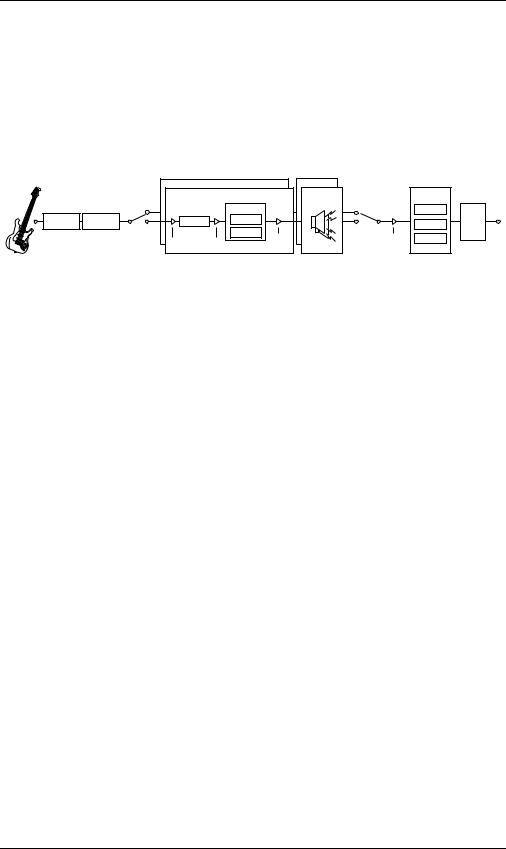
SIGNAL ROUTE
When you plug into ToneLabSE the signal passes through the following stages.
You might want to glance at the explanations in “A Guitarist’s Guided Panel Tour” (p.5) while you read this section.
INSERT PEDAL
EFFECT EFFECT
|
AMP MODEL |
VALVE REACTOR |
CABINET |
|
|
|
|||
|
16 TYPE |
|
MODEL |
|
EFFECT |
|
|||
|
|
|
|
|
CABINET |
|
|
||
|
AMP MODEL |
|
VALPOWVERREACTORAMP |
10 TYPE |
|
|
|
||
|
16 TYPE |
|
|
|
|
|
|||
A ch |
|
|
MODEL |
A ch |
|
|
|||
PRE AMP |
|
POWER AMP |
|
11 TYPE |
MODULATION |
|
|||
|
|
CLASS A |
|
|
|
OUTPUT |
|||
|
PRE AMP |
|
CLASS A |
CH |
|
|
DELAY |
||
B ch |
|
|
|
CLASS AB |
|
B ch |
SELECT |
||
GAIN |
VR GAIN |
|
CLASS AB VOLUME |
|
|
|
|||
|
|
|
|
|
|
||||
|
|
|
|
|
CH |
|
VOLUME |
REVERB |
|
|
GAIN |
VR GAIN |
|
VOLUME |
|
|
|||
|
|
|
PEDAL |
|
|
||||
|
|
|
|
|
|
|
|
|
|
MODES
ToneLabSE has a Program Select mode (where you can switch programs) and an Effect On/Off mode (where you can switch individual effects on/off). To switch between these modes, simply press the FX ON/OFF pedal which can be done even while you are performing.
AMP AND EFFECT SETTINGS (EDIT)
The six model selectors, six value knobs, and various buttons let you edit the amp and effect settings directly and intuitively. You can use the CHAIN switch to change the order in which the modulation, delay, and reverb effects are connected. For the amp and cabinet model, you can make settings for two channels (A and B) and switch between them while you perform.
REALTIME EXPRESSION AND CONTROL PEDALS
You can use the expression pedal and control pedal to control wah, volume, or effect parameters with your feet. Use the EXPRESSION button or the CONTROL button to specify the parameter that will be controlled by the corresponding pedal.
SAVING A PROGRAM
By using the WRITE button, all settings you make can be saved as a “program.” When doing so, you should use the RENAME button to give the program a new name. Once you’ve saved a program, you can use the program select pedals to recall it instantly (in Program Select mode).
MIDI AND OUTPUT DESTINATION SETTINGS
The GLOBAL button lets you make MIDI-related settings and specify the destination to which ToneLabSE is connected. The settings you make here are automatically saved within ToneLabSE so there’s no need to perform the WRITE operation.
4

A Guitarist’s Guided Panel Tour
Here we’re going to learn about the buttons and other controls on ToneLabSE’s top and rear panel.
HINT: The inside back cover of this manual folds out to reveal a big picture of ToneLabSE’s top panel, rear panel, and display. Leave this folded out as you continue reading so you’ll be able to see the panel diagram while you read about each section.
THE TOP PANEL
1 MODEL SELECT SECTION
Here you can select the model of amp, cabinet and effect models.
1.1 MODEL select buttons
Use these when selecting the effect category you want to edit with value knobs 1–6, and when switching effects on/off. If an effect you’re using is ON it will be lit (or blinking during editing), and if OFF it will be dark.
Press a button once and its LED will blink; now you can use value knobs 1–6 to edit the parameters of that effect.
If you want turn off an effect that is currently on, press the model select button for the appropriate effect once (it blinks), and then press that model switch button once again to turn it off (dark); the name display will indicate [--OFF--].
The pedal effect is placed in front of the amp model and the modulation, delay, and reverb are placed after the cabinet model.
NOTE: While the cabinet model select button is blinking, you can use the value knobs to adjust the parameters of the amp model.
NOTE: The amp and cabinet model select buttons will change color depending on the channel you select; they will be lit (or blinking) green when channel A is selected, and red when channel B is selected.
NOTE: The reason that modulation, delay, and reverb effects are placed after the amp — rather than before it as a “stompbox” would be — is that they sound better and more realistic. For example, REVERB emulates the sound created by a room or hall. So, logic dictates that if we’re going to add it to our sound, the closer to the end of the signal chain we put it, the more “real” and natural it’s going to sound. The same is true for DELAY and MODULATION effects — they’re going to sound more natural if added near the end of your signal path, not at its beginning. Also, if you’re using a crunch or high gain lead sound then it makes much more sense to add effects like ROTARY, ROOM (reverb), or DELAY after it’s been distorted, rather than before.
1.2 INSERT button
Use this to switch the insert effect on/off. This will be lit if the signal input/output to the external effect is ON, or dark if it is OFF. The external effect is placed before the pedal effect.
5
Creating Playing Setup Panel Tour Introduction and Storing

1.3 PRES-NR (Presence/Noise Reduction) button
Use this to change the presence and noise reduction settings of the amp. While this button is blinking, you can use value knob [3] to adjust the presence, and value knob [4] to adjust the noise reduction. This will light (blink) green when channel A is selected, or red when channel B is selected.
1.4 PEDAL selector
This lets you select one of the sixteen pedal effect models ToneLabSE offers. When you turn the PEDAL selector, the PEDAL select button will blink, and you can use value knobs 1–6 to adjust the pedal effect parameters. (For an explanation of each effect, refer to p.35–.) As stated before, pedal effects are connected before the amp.
NOTE: The parameters will be initialized when you switch effect types.
1.5 AMP MODEL selector
This lets you select from sixteen types of classic amp models, including the legendary VOX AC30TBX. (For details, see p.23.) When you turn the AMP MODEL selector, the AMP MODEL select button will blink, and you can use value knobs 1–6 to adjust its parameters.
The operating mode of the preamp and power amp, the response of the tone controls, and their placement within the circuit will change depending on the type of amp you select here, precisely replicating the exact gain and tonal character of the original amp. The all-important power amp stage (class A or AB) and negative-feedback circuit (or lack thereof) are also carefully simulated.
1.6 CABINET MODEL selector
This selects one of eleven cabinet models that replicate the shape and size of the cabinet and the type and number of its speakers. (For details, refer to p.32.) When you turn the CABINET MODEL selector, the CABINET MODEL select button will blink.
NOTE: While the CABINET MODEL select button is blinking, you can use the value knobs to adjust its parameters.
1.7 MODULATION selector
This selects one of eleven modulation effect models. When you turn the MODULATION selector, the MODULATION select button will blink, and you can use value knobs 1–6 to adjust the parameters of the modulation effect. (For details on each effect, refer to p.39–.)
NOTE: The parameters will be initialized when you switch effect types.
1.8 DELAY selector
This selects one of eleven delay effect models. When you turn the DELAY selector, the DELAY select button will blink, and you can use value knobs 1–6 to adjust the parameters of the delay effect. (For details on each effect, refer to p.45–.)
NOTE: The parameters will be initialized when you switch effect types.
6

1.9 REVERB selector
This selects one of eleven reverb effect models. When you turn the REVERB selector, the REVERB select button will blink, and you can use value knobs 1– 6 to adjust the parameters of the reverb effect. (For details on each effect, refer to p.48–.)
NOTE: The parameters will be initialized when you switch effect types.
2 EDIT SECTION
2.1 Edit category LEDs
One of the LEDs will blink to indicate the category of effect you are currently editing.
When adjusting the parameters, an LED will blink to indicate the line of parameter names that you are adjusting.
2.2 Value knobs 1–6
Use these to adjust the parameters of the effects or amp model. Your adjustments will modify the effect whose MODEL select button you pressed (i.e., the button that is blinking). The LEDs below the knobs will light to indicate the knobs that are available.
For details on the parameter controlled by each knob, refer to p.35–. (From the left, we refer to these as value knobs 1–6.)
When the EXPRESSION button or CONTROL button is blinking, these knobs adjust the corresponding functions.
When you are making RENAME or GLOBAL settings, or when executing the WRITE operation, you can use value knob 6 to change values.
Creating Playing Setup Panel Tour Introduction and Storing
7

3 CHAIN/GLOBAL/RENAME/WRITE/EXIT/DISPLAY SECTION
This area displays the name of the program, and the name and value of the parameter you are editing in the amp or effect section. Use RENAME to edit the name of the program, and WRITE to save the program.
CHAIN lets you change the connection order of the modulation, delay, and reverb effects. GLOBAL lets you make MIDI and output settings.
3.1 ▲, ▼ buttons
Use these to edit the value of parameters.
3.2 √, ® buttons
Use these to select the parameter you want to edit, or to edit the program name.
3.3 CHAIN button
Use this to change the connection order of the modulation, delay, and reverb effects. Use value knob 6 or the ▲, ▼ buttons to edit the value.
3.4 GLOBAL button
Use this to make settings related to MIDI or to ToneLabSE’s audio output.
Press the GLOBAL button and use the √, ® buttons to move through the menu items in the order shown below. After you have selected a menu item, use value knob 6 or the ▲, ▼ buttons to adjust the value.
OUT SEL: |
Specifies the output destination |
(p.13) |
CH HOLD: |
Specifies whether the channel (A/B) selection will be |
(p.17) |
|
maintained when you switch programs |
|
MIDI CH: |
Specifies the MIDI channel |
(p.59) |
PCHG OUT: |
Specifies the program change message output setting |
(p.60) |
CCHG I/O: |
Specifies the control change message input/output setting(p.60) |
|
SYEX OUT: |
Specifies the system exclusive message output setting |
(p.61) |
DUMP CUR: Dumps the current program data from the MIDI OUT con- (p.62) nector
DUMP ALL: Dumps all of ToneLabSE’s data from the MIDI OUT con- (p.62) nector
3.5 RENAME button
Use this to change the program name (p.21).
Use the √, ® buttons to move between spaces (characters) in the display, and use value knob 6 or the ▲, ▼ buttons to change the character at that space.
3.6 WRITE button
Use this when you want to save the settings you’ve created (p.22).
3.7 EXIT button
Use this to abort a program-write operation or to cancel a GLOBAL setting.
By pressing and holding this button for a longer time, you can activate/cancel the Key Lock function, which disables operation of the buttons, selectors, and knobs (p.18).
8

3.8 Name display
Displays program names, effect names, or parameter names.
3.9 Valve icon
Indicates the number and type of power valve – a.k.a. “vacuum tube” – used in the original amp that is being modeled.
3.10 Value display
Indicates the value of the parameter you are editing.
If the displayed parameter value matches the original value (i.e., the value saved in the program), the ORIG (original value) icon will appear.
If you have edited any parameter of the program, the EDIT icon will appear.
4 CONTROL SETUP SECTION
4.1 CONTROL pedal setting button
Use this to make control pedal settings. While this button is blinking, you can use value knobs 1–2 to edit the control pedal settings.
4.2 EXPRESSION pedal setting button
Use this to make expression pedal settings. While this button is blinking, you can use value knobs 1–6 to edit the expression pedal settings.
If this is lit while you’re editing, the expression pedal Quick Assign function is available.
HINT(Quick Assign): If the expression pedal setting button is lit while you are editing an effect, you can use the expression pedal Quick Assign function. To assign the parameter shown in the name display to expression pedal 1, simply press and hold the expression pedal setting button for one second. If you want to assign the parameter to expression pedal 2, press and hold the control pedal setting button for one second. When the assignment is completed, the name display will indicate COMPLETE.
5 BANK DISPLAY/TUNER DISPLAY
5.1 Bank display
Indicates the bank number. If the tuner is operating, this indicates the note name. (p.51)
5.2 Tuner display
If the tuner is on, this displays the pitch you are playing. (p.51)
6 BANK/PROGRAM/CHANNEL/SELECT SECTION
6.1 BANK UP/DOWN pedals
In Program Select mode, press BANK UP to increment the bank by one, or BANK DOWN to decrement it by one. In Effect On/Off mode, you can use the BANK DOWN pedal to switch INSERT (the external effect) on/off.
6.2 Program select pedals, Program LEDs
Use these to select programs. The program LED at the upper left of each pedal will light accordingly.
Creating Playing Setup Panel Tour Introduction and Storing
9

In Effect On/Off mode, these switches individually switch the Pedal, Modulation, Delay, and Reverb effects on/off.
6.3 A/B ch channel select pedal, Channel LEDs
Use this to change channels within the currently selected program. The channel LEDs located above the pedal will light accordingly (green when channel A is selected, red when channel B is selected).
7 FX ON/OFF SWITCH
Press this switch when you want to switch to Effect On/Off mode and the LED at the upper left of the pedal will light.
In Effect On/Off mode you can use the program select pedals to individually switch the Pedal, Modulation, Delay, and Reverb effects on/off.
If you press and hold this switch for 0.5 seconds or longer, the output will be bypassed. If you press and hold this pedal for one second or longer, the output will be muted. The tuner will operate when ToneLabSE is bypassed or muted.
To cancel bypass or mute (Tuner), press this switch once again.
8 EFFECT CONTROL SECTION
8.1 CONTROL (Control switch)
This pedal controls the effect function specified by the Control switch setting.
8.2 EXP1, EXP2 (Expression pedal 1, Expression pedal 2)
These pedals control the effect parameter you assigned as the expression pedal setting; e.g., volume, wah, or other effect parameter. Pressing down firmly on an expression pedal will activate a switch underneath the pedal, letting you turn the assigned effect on/off (except when you’ve assigned volume or an amp parameter).
9 VALVE
9.1 Valve window
ToneLabSE contains a 12AX7 (ECC83) valve (“vacuum tube”).
NOTE: The valve cover and or valve may break if it’s subjected to impact. If the valve cover breaks, please have it replaced; leaving a damaged cover may lead to the valve itself to become damaged.
10
REAR PANEL
10 POWER SUPPLY
10.1 ~AC9V
Connect the included AC/AC power supply here.
10.2 STANDBY button
Turns the power on/off.
11 INPUTS AND OUTPUTS
11.1 INPUT jack
Connect your guitar to this jack.
11.2 INSERT jacks (SEND, RETURN)
You can connect an external effect processor or stompbox to these jacks.
Connect SEND to the input of your external effect device.
Connect RETURN to the output of your external effect device.
11.3 LEVEL knob
Adjusts the output level from the OUTPUT jacks and the PHONE jack.
11.4 OUTPUT jacks (L/MONO, R)
These are analog output jacks (balanced/unbalanced TRS). If you’re using a mono output, connect the L/MONO jack.
11.5 PHONE jack (stereo)
Connect your headphones to this jack.
12 MIDI
12.1 MIDI OUT connector
This connector transmits MIDI data. Use it when you want to control a connected external MIDI device.
12.2 MIDI IN connector
This connector receives MIDI data. Use it when you want to control ToneLabSE from a connected external MIDI device.
Creating Playing Setup Panel Tour Introduction and Storing
11

12
Setup
NOTE: You must turn off the power of all your equipment before you make connections. If you ignore this warning, you may damage your speaker system or experience malfunctions!
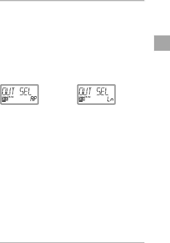
OUTPUT SETTINGS
Here’s how to specify whether you’re connecting ToneLabSE to a guitar amp or to a mixer/recorder.
1.Press the GLOBAL button, and use the √, ® buttons to make the display read “OUT SEL.”
2.Use value knob 6 or the ▲, ▼ buttons to set the value.
When connecting to a guitar amp |
When connecting to a mixer/recorder |
||||||
|
|
|
|
|
|
|
|
|
|
|
|
|
|
|
|
NOTE: With the factory settings, “AP” is selected.
BASIC CONNECTIONS
1.Use audio cables to connect ToneLabSE’s OUTPUT L/MONO and R jacks (11.4) to a mixer/recorder or guitar amp (p.13, 14). If desired, you can also connect an external effect processor. To do this simply connect SEND to the input of your external processor, and RETURN to the output of your external processor.
NOTE: If you’re making connections in mono, use the OUTPUT L/MONO jack. However to take the fullest advantage of ToneLabSE’s sound, we strongly recommend that you use stereo connections.
If you are using headphones, plug them into the PHONES jack (11.5).
NOTE: Signal from the OUTPUT jack(s) will still be heard even if headphones are plugged in. If you only want to hear signal from headphones you must disconnect any cables from the Output jacks or turn off or lower any equipment ToneLabSE is connected to.
2.Turn the LEVEL knob (11.3) located on the rear panel of ToneLabSE all the way toward the left (as seen from the rear), setting the volume to 0.
3.Connect the included AC/AC power supply to the rear panel AC9V power supply jack (10.2), and then connect the plug to an AC outlet.
4.Plug your guitar into the rear panel INPUT jack (11.1).
5.Turn down the volume of your amp or mixer so you don’t hear crackles or pops when the power is turned on. Then turn on the STANDBY switch (10.1) to turn on the power.
13
Creating Playing Setup Panel Tour Introduction and Storing
6.If you’ve connected ToneLabSE to a mixer/recorder, press the GLOBAL switch to access the OUT SEL menu, and use value knob 6 or the ▲, ▼ buttons to select “Ln” (LINE). If you’ve connected ToneLabSE to a guitar amp, select “AP” (AMP).
7.To adjust the volume, turn up your amp or mixer and ToneLabSE’s rear panel LEVEL knob to a desired level (11.3).
NOTE: Since ToneLabSE uses an actual valve (vacuum tube), it will produce no sound for several seconds until the valve warms up. This isn’t a malfunction – it’s just the nature of valves.
|
Headphones |
to your mixer/recorder |
|
||
|
|
|
or guitar amp |
|
|
|
|
|
LINE/AMP |
|
|
|
|
|
|
AC/AC |
|
|
to your MIDI |
External effect processor |
power supply |
|
|
|
|
|
|||
|
RETURN |
|
|
|
|
Guitar |
sequencer/computer |
SEND |
|
to an |
|
|
|
|
~AC9V |
AC outlet |
|
|
|
|
|
||
|
|
|
OUTPUT |
Monaural phone jack INPUT |
|
ToneLabSE |
L/MONO |
R |
INPUT |
PHONES |
|
||
|
|
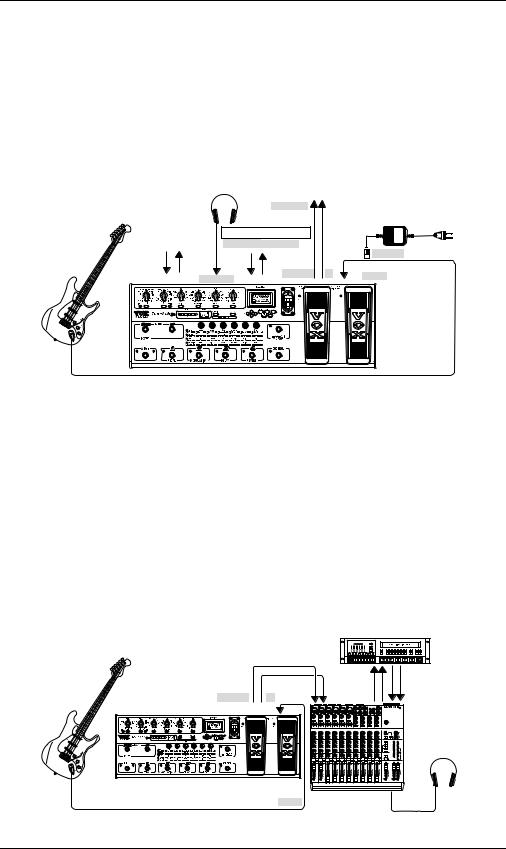
USING TONELABSE WITH A MIXER OR RECORDER
EXAMPLE OF CONNECTIONS TO A MIXER OR RECORDER
•When using ToneLabSE for direct-line recording, connect the OUTPUT L/ MONO and R jacks to the input jacks of your mixer or recorder. Press the GLOBAL switch to access the OUT SEL menu, and use value knob 6 or the ▲, ▼ buttons to select “Ln” (LINE).
HINT: If you’re using a mono connection, use the OUTPUT L/MONO jack only.
HINT: If you’re using a stereo connection, pan the input channels of your mixer/ recorder to the far left and right respectively.
Guitar |
|
Tape |
Tape |
|
Send |
Return |
|
OUTPUT |
LINE IN 1 |
LINE IN 2 |
|
L/MONO |
R PAN L |
PAN R |
|
|
|
Headphones |
|
ToneLabSE |
|
|
|
Monaural phone jack |
Mixer/recorder |
PHONES |
|
INPUT |
|||
|
|
14
USING TONELABSE WITH A GUITAR AMP(S)
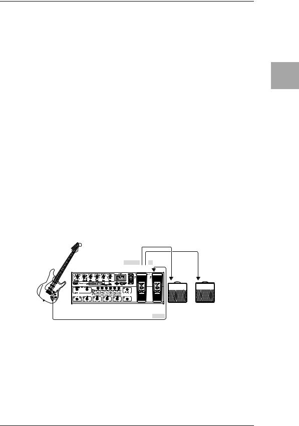
EXAMPLE OF CONNECTION TO A GUITAR AMP (OR AMPS)
•If you are connecting ToneLabSE to one or more guitar amps, connect the OUTPUT L/MONO and R jacks to the input jack of your guitar amp(s). If desired, you can also connect an external effect processor; connect SEND to the effect processor’s input, and RETURN to its output. Press the GLOBAL switch to access the OUT SEL menu, and use value knob 6 or the ▲, ▼ buttons to select “AP” (AMP).
HINT: If ToneLabSE is connected immediately before a combo amp or amp head, set the tone controls of your guitar amp to their center positions and then adjust for taste. To avoid unintentional distortion, press and hold the FX ON/OFF (Effect On/ Off) pedal for 0.5 seconds to bypass ToneLabSE, and adjust the rear panel LEVEL knob so that the volume is the same as when your guitar is connected directly to the amp.
HINT: If you’re connecting ToneLabSE to a guitar amp that has a jack allowing you to connect directly before the power amp (such as Return or Main In), set the OUT SEL menu item to “Ln” (LINE), and then connect ToneLabSE to that jack. If you want to take advantage of the tonal character of that amp (and cabinet), you may want to turn ToneLabSE’s CABINET setting “OFF.”
HINT: When the program name is displayed, you can press and hold the EXIT switch for one second or longer to activate the Key Lock function; this disables operation of the buttons, selectors, and knobs. (The name display will indicate KEY LOCK for one second, and the value knob LEDs will go dark.) To cancel the Key Lock function, press and hold the EXIT switch again for one second or longer. (The name display will indicate LOCK OFF for one second.)
Guitar
OUTPUT |
|
L/MONO |
R |
ToneLabSE |
|
Monaural phone jack
INPUT
INPUT |
INPUT |
||
Monaural |
Monaural |
||
phone jack |
phone jack |
||
|
|
|
|
Guitar amp(s)
USING TONELABSE WITH A MIDI DEVICE OR COMPUTER
By using MIDI you can control ToneLabSE from a sequencer or control an external MIDI device from ToneLabSE. You can also save ToneLabSE programs on a sequencer or MIDI data filer that is able to transmit and receive MIDI exclusive data, and then load the program data back into ToneLabSE when desired.
HINT: For details on MIDI connections refer to p.59.
Creating Playing Setup Panel Tour Introduction and Storing
15
 Loading...