


E F G S J 2

Welcome to VOX .......................... |
5 |
Bienvenue à VOX ! ..................... |
11 |
Willkommen bei VOX ................. |
17 |
Bienvenido a VOX ...................... |
23 |
VOX ............................. |
29 |
3
IMPORTANT SAFETY INSTRUCTIONS
•Read these instructions.
•Keep these instructions.
•Heed all warnings.
•Follow all instructions.
•Do not use this apparatus near water.
•Mains powered apparatus shall not be exposed to dripping or splashing and that no objects filled with liquids, such as vases, shall be placed on the apparatus.
•Clean only with dry cloth.
•Do not block any ventilation openings. Install in accordance with the manufacturer’s instructions.
•Do not install near any heat sources such as radiators, heat registers, stoves, or other apparatus (including amplifiers) that produce heat.
•Do not defeat the safety purpose of the polarized or grounding-type plug. A polarized plug has two blades with one wider than the other. A grounding type plug has two blades and a third grounding prong. The wide blade or the third prong are provided for your safety. If the provided plug does not fit into your outlet, consult an electrician for replacement of the obsolete outlet. (for USA and Canada)
•Protect the power cord from being walked on or pinched particularly at plugs, convenience receptacles, and the point where they exit from the apparatus.
•Only use attachments/accessories specified by the manufacturer.
•Unplug this apparatus during lightning storms or when unused for long periods of time.
•Turning off the power switch does not completely isolate this product from the power line so remove the plug from the socket if not using it for extended periods of time.
•Install this product near the wall socket and keep the power plug easily accessible.
•WARNING—This apparatus shall be connected to a mains socket outlet with a protective earthing connection.
•Refer all servicing to qualified service personnel. Servicing is required when the apparatus has been damaged in any way, such as power-supply cord or plug is damaged, liquid has been spilled or objects have fallen into the apparatus, the apparatus has been exposed to rain or moisture, does not operate normally, or has been dropped.
•Do not install this equipment on the far position from wall outlet and/or convenience receptacle.
•Do not install this equipment in a confined space such as a box for the conveyance or similar unit.
•Excessive sound pressure from earphones and headphones can cause hearing loss.
•Use only with the cart, stand, tripod, bracket, or table specified by the manufacturer, or sold with the apparatus. When a cart is used, use caution when moving the cart/ apparatus combination to avoid injury from tip-over.
CALIFORNIA USA ONLY
California 93120 Compliant for Formaldehyde. “The Airborne Toxic Control Measure to reduce Formaldehyde Emissions from Composite Wood Products.”
The lightning flash with arrowhead symbol within an equilateral triangle, is intended to alert the user to the presence of uninsulated “dangerous voltage” within the product’s enclosure that may be of sufficient magnitude to constitute a risk of electric shock to persons.
The exclamation point within an equilateral triangle is intended to alert the user to the presence of important operating and maintenance (servicing) instructions in the literature accompanying the product.
THE FCC REGULATION WARNING (for USA)
This equipment has been tested and found to comply with the limits for a Class B digital device, pursuant to Part 15 of the FCC Rules. These limits are designed to provide reasonable protection against harmful interference in a residential installation. This equipment generates, uses, and can radiate radio frequency energy and, if not installed and used in accordance with the instructions, may cause harmful interference to radio communications. However, there is no guarantee that interference will not occur in a particular installation. If this equipment does cause harmful interference to radio or television reception, which can be determined by turning the equipment off and on, the user is encouraged to try to correct the interference by one or more of the following measures:
•Reorient or relocate the receiving antenna.
•Increase the separation between the equipment and receiver.
•Connect the equipment into an outlet on a circuit different from that to which the receiver is connected.
•Consult the dealer or an experienced radio/TV technician
for help.
Unauthorized changes or modification to this system can void the user’s authority to operate this equipment.
Notice regarding disposal (EU only)
When this “crossed-out wheeled bin” symbol is displayed on the product, owner’s manual, battery, or battery package, it signifies that when you wish to dispose of this product, manual, package or battery you must do so in an approved manner. Do not discard this product, manual, package or battery along with ordinary household waste. Disposing in the correct
manner will prevent harm to human health and potential damage to the environment. Since the correct method of disposal will depend on the applicable laws and regulations in your locality, please contact your local administrative body for details. If the battery contains heavy metals in excess of the regulated amount, a chemical symbol is displayed below the “crossed-out wheeled bin” symbol on the battery or battery package.
*All product names and company names are the trademarks or registered trademarks of their respective owners.
4

Welcome to VOX
Many thanks for adding the VOX AC30VR/AC15VR amplifier to your sonic arsenal.
It was designed by our UK based VOX engineering team and built by our state of the art, vertically integrated manufacturing facility and we’re sure it’ll give you countless hours of great guitar tones that will feel as good as they sound! To insure a long and happy relationship with your amplifier, please read this manual at least once, and (as they say), “use the product as directed.” Keep the manual for future reference after you’ve read it.
WHAT IS VR?
The VR series of amplifiers are designed, as to what we believe are the next generation of “hybrid” guitar amplifiers. What does HYBRID mean, you may ask? Well, basically “hybrid” means that it utilizes a mixture of technologies—in this case those technologies are Tube and Solid State.
The Preamp stages consist of discrete transistors for sound generation, and integrated circuits (op-amps) to do signal management that would not be done effectively with transistors alone—i.e. channel switching, etc.
The Power amp stage uses a 12AX7 vacuum tube (or valve, depending where you live in the world) in a configuration that we at VOX call Valve Reactor.
The patented Valve Reactor power amp technology is used in all Valvetronix products. It was originally designed for the award winning VOX Valvetronix modelling guitar amplifier range, and now we have taken that same technology and further revised it into the format that is built into your AC30VR/ AC15VR amplifier.
HOW DOES IT WORK?
It basically works by having each half of the 12AX7 (the 12AX7 tube is actually two identical tubes in one glass tube a.k.a. dual triode) and configuring it to work as a small tube power amplifier. This circuit provides all the tonality and feel of an all-tube power amp. Obviously this “small” power amp would not be very loud if it was connected directly to a loud- speaker—therefore the tube circuit is connected to a larger, completely transparent solid-state power amplifier, that is run very cleanly so that it does not add its own colouration to the tube signal.
This power output amplifier also has some special circuits that feed the loudspeaker impedance information back to the tube power amplifier in order to give it the loose sound & feel that an all-tube amp does.
SO WHAT DOES THIS MEAN?
We think that the VOX VR amplifier range brings you superb tone (vintage & modern) that includes the high harmonic content and compression that goes all the way back to the original VOX AC15 & 30 amplifiers that were created more than 50 years ago, and are still revered to this day.
5
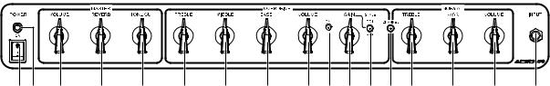
AC30VR FRONT PANEL FEATURES
1 2 |
3 |
4 |
5 |
6 |
7 |
1. MAINS POWER SWITCH
Turns your AC30VR OFF/ON from the connected mains power.
2. POWER LED
Illuminates RED when your amplifier is switched on, and is also connected to a suitable mains power supply.
8
9 10 11 12 13 14 |
15 |
16 |
17 |
12. OVERDRIVE STYLE BUTTON
This button changes the distortion characteristics (STYLE) of the Overdrive channel—OUT=OD1, IN=OD2.
OD1 is a warm natural “vintage” overdrive flavour, ideal for “blues” based sounds.
OD2 is a harder, more aggressive, high gain style distortion, more suited to “modern” playing.
MASTER
3. VOLUME
This controls the amount of volume produced by the AC30VR’s Valve Reactor power amplifier circuit, and therefore the overall volume that your AC30VR supplies to any of the loudspeaker systems that are connected.
4. REVERB
This controls the amount of digital reverb that is mixed with the direct signal to produce a slight shimmer of reverb (low settings) to concert hall depth (at high settings).
The built-in digital reverb can be cancelled or activated by the optional VFS2 Dual Footswitch. (Channel-Reverb)
5. TONE CUT
This circuit is placed in the power amp as opposed to the preamp section like the Treble and Bass controls. What this does is the opposite of what you may think. Turning it clockwise will decrease the higher frequencies and turning it counterclockwise adds higher frequencies.
OVERDRIVE CHANNEL
6. TREBLE CONTROL
This controls the amount of TREBLE in the Overdrive channel.
7. MIDDLE CONTROL
This controls the amount of MIDDLE frequency in the Overdrive channel.
8. BASS CONTROL
This controls the amount of BASS in the Overdrive channel.
9. VOLUME CONTROL
This controls the amount of overdrive generated by the preamp signal that is sent to the Valve Reactor power amplifier. Use this to set the loudness required for your use, and also to balance the overdrive sound against your clean (Normal) sound.
10. CHANNEL SELECT LED
Illuminates RED when the Overdrive channel is selected.
11. GAIN CONTROL
This regulates the amount of preamp “gain” and therefore the amount of overdrive or distortion that is generated by the Overdrive Channel. Like the Normal Volume control, lower settings mean less distortion, higher settings mean much, much more distortion!
13. CHANNEL SWITCHING BUTTON
This button controls whether your amplifier is set for Normal or Overdrive—OUT = NORMAL, IN = OVERDRIVE.
Your AC30VR can also be channel switched by using the optional VFS2 Dual Footswitch (connected via the back panel Footswitch Jack). This function can only be operated when the front panel button is “IN” position.
When the Normal channel is selected, the LED is not illumi- nated—when the Overdrive channel is selected, the Red LED is illuminated.
NORMAL CHANNEL
14. TREBLE CONTROL
This controls the amount of TREBLE in the Normal channel.
15. BASS CONTROL
This controls the amount of BASS in the Normal channel.
16. VOLUME CONTROL
This controls the volume of the clean (NORMAL) channel. At lower settings the sound will be very clean and bright, at higher settings the sound will become somewhat thicker and warmer, whilst at the highest settings the sound will “break up” into a natural vintage style distortion.
As different types of electric guitars have vastly different amounts of tonal qualities and output levels, your guitar will have a major influence on where you will need to set the position of the controls on this amplifier to achieve the response you desire.
Please Note—for this control to be functional the amplifier channel switching facility needs to be set to the Normal channel.
17. INPUT JACK
Connect your guitar into this socket.
6
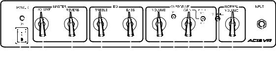
AC15VR FRONT PANEL FEATURES
|
|
|
|
|
|
|
|
|
|
|
|
|
|
|
|
|
|
|
|
|
|
|
|
|
|
|
|
|
|
|
|
|
|
|
|
|
|
|
|
|
|
|
|
|
|
|
|
|
|
|
|
|
|
|
|
|
|
|
|
|
|
|
|
|
|
|
|
|
|
|
|
|
|
|
|
|
|
|
|
|
|
|
|
|
|
|
|
|
|
|
|
|
|
|
|
|
|
|
|
|
|
|
|
|
|
|
|
|
|
|
|
1 |
|
|
2 |
3 |
4 |
5 |
6 |
||||||||
1. MAINS POWER SWITCH
Turns your AC15VR OFF/ON from the connected mains power.
2. POWER LED
Illuminates RED when your amplifier is switched on, and is also connected to a suitable mains power supply.
MASTER
3. VOLUME
This controls the amount of volume produced by the AC15VR’s Valve Reactor power amplifier circuit, and therefore the overall volume that your AC15VR supplies to any of the loudspeaker systems that are connected.
4. REVERB
This controls the amount of digital reverb that is mixed with the direct signal to produce a slight shimmer of reverb (low settings) to concert hall depth (at high settings).
The built-in digital reverb can be cancelled or activated by the optional VFS2 Dual Footswitch. (Channel-Reverb)
EQ
5. TREBLE CONTROL
This controls the amount of TREBLE in your sound.
6. BASS CONTROL
This controls the amount of BASS in your sound.
OVERDRIVE CHANNEL
7.VOLUME CONTROL
This controls the amount of overdrive generated by the preamp signal that is sent to the AC15VR’s Valve Reactor power amplifier. Use this to set the loudness required for your use, and also to balance the overdrive sound against your clean (Normal) sound.
8. CHANNEL SELECT LED
Illuminates RED when the Overdrive channel is selected.
9. GAIN CONTROL
This regulates the amount of preamp “gain” and therefore the amount of overdrive or distortion that is generated by the Overdrive Channel. Like the Normal Volume control, lower settings mean less distortion, higher settings mean much, much more distortion!
10. OVERDRIVE STYLE BUTTON
This button changes the distortion characteristics (STYLE) of the Overdrive channel—OUT=OD1, IN=OD2.
OD1 is a warm natural “vintage” overdrive flavour, ideal for “blues” based sounds.
OD2 is a harder, more aggressive, high gain style distortion, more suited to “modern” playing.
|
|
|
|
|
|
|
|
|
|
|
|
|
|
|
|
|
|
|
|
|
|
|
|
|
|
|
|
|
|
|
|
|
|
|
|
|
|
|
|
|
|
|
|
|
|
|
|
|
|
|
|
|
|
|
|
|
|
|
|
|
|
|
|
|
|
|
|
|
|
|
|
|
|
|
|
|
|
|
|
|
|
|
|
|
|
|
|
|
|
|
|
|
|
|
|
|
|
|
|
|
|
|
|
|
|
|
|
|
|
|
|
|
|
|
|
|
|
|
|
|
|
|
|
|
|
|
|
|
|
|
|
|
|
|
|
|
|
|
|
|
|
|
|
|
|
|
|
|
|
|
|
|
|
|
|
|
|
|
|
|
|
|
|
|
|
|
|
|
|
|
|
|
|
|
|
|
|
|
|
|
|
|
|
|
|
|
|
|
|
|
|
|
|
|
|
|
|
7 |
8 |
9 |
10 |
11 |
12 |
13 |
|||||||||||
11. CHANNEL SWITCHING BUTTON
This button controls whether your amplifier is set for Normal or Overdrive—OUT = NORMAL, IN = OVERDRIVE. Your AC15VR can also be channel switched by using the optional VFS2 Dual Footswitch (connected via the back panel Footswitch Jack). This function can only be operated when the front panel switch is “IN” position.
When the Normal channel is selected, the LED is not illumi- nated—when the Overdrive channel is selected, the Red LED is illuminated.
NORMAL CHANNEL
12. VOLUME CONTROL
This controls the volume of the clean (NORMAL) channel. At lower settings the sound will be very clean and bright, at higher settings the sound will become somewhat thicker and warmer, whilst at the highest settings the sound will “break up” into a natural vintage style distortion.
As different types of electric guitars have vastly different amounts of tonal qualities and output levels, your guitar will have a major influence on where you will need to set the position of the controls on this amplifier to achieve the response you desire.
Please Note—for this control to be functional the amplifier channel switching facility needs to be set to the Normal channel.
13. INPUT JACK
Connect your guitar to this socket.
7
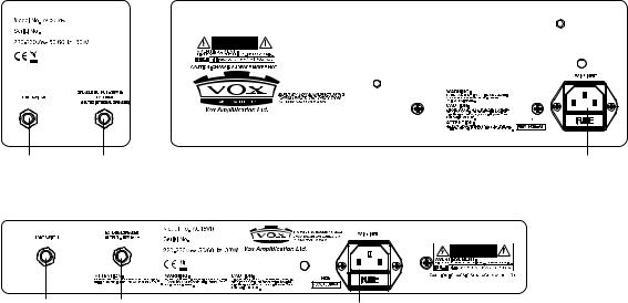
REAR PANEL FEATURES
AC30VR
1 2 3 AC15VR
12
1.FOOTSWITCH JACK
Connect the optional VFS2 Dual Footswitch to this jack.
2. EXTERNAL SPEAKER OUTPUT JACK
An external loudspeaker system can be connected to your amplifier by using this socket. This socket disconnects the amplifier from the internal loudspeaker.
WARNING! To ensure that your system works correctly, you must observe the following points.
a)Only use an external cabinet with a combined impedance of 8ohms.
b)Don’t connect a speaker whose rated input capacity is less than 15 watts (for AC15VR) or 30 watts (for AC30VR). The speaker may be destroyed if you ignore this caution—not recommended!
c)You must use a speaker cable to connect an external speaker. Don’t use a shielded cable like the one you use to connect a guitar to an amp.
d)You must turn off the power before connecting the cable. Connecting the cable while the power is turned on may damage your amp.
3
3. MAINS POWER CONNECTOR/FUSE
The mains power required by your amplifier is connected using this device.
WARNING! Use only the power cord supplied with your amplifier, or a replacement of the exact same specification.
WARNING! Only connect this amplifier to a suitable mains power supply that matches the rating indicated on the back panel of your AC30VR/AC15VR amplifier. IF IN ANY DOUBT CONTACT YOUR DEALER!
8
SPECIFICATIONS
AC30VR
Twin channel, guitar amplifier with 2x 12 inch VX 12 Celestion custom made loudspeaker and digital reverb.
30 watts RMS power output utilising VOX proprietary Valve Reactor power amplifier technology with built-in 12AX7/ ECC83 tube (valve).
•Dimensions (W x D x H):
702 x 265 x 556 mm (27.64 x 10.43 x 21.89 inches)
•Weight: 23 kg (50.71 pounds)
•Output Power: 30 Watts RMS into 8 Ohms
•Speaker: 2x 12", 16 Ohm VX12 Celestion custom speaker
•Inputs: Input jack, Footswitch jack
•Outputs: External LoudSpeaker jack
•Options: VFS2 Dual Footswitch
AC15VR
Twin channel, guitar amplifier with 1x 12 inch VX 12 Celestion custom made loudspeaker and digital reverb.
15 watts RMS power output utilising VOX proprietary Valve Reactor power amplifier technology with built-in 12AX7/ ECC83 tube (valve).
•Dimensions (W x H x D):
602 x 265 x 456 mm (23.70 x 10.43 x 17.95 inches)
•Weight: 16.4 kg (36.16 pounds)
•Output Power: 15 Watts RMS into 8 Ohms
•Speaker: 1x 12", 8 Ohm VX12 Celestion custom speaker
•Inputs: Input jack, Footswitch jack
•Outputs: External LoudSpeaker jack
•Options: VFS2 Dual Footswitch
*Specifications are subject to change without notice.
9
INFORMATIONSIMPORTANTESDESECURITE
•Lisez attentivement ces instructions.
•Veuillez conserver ces instructions.
•Observez tous les avertissements.
•Suivez toutes les consignes à la lettre.
•N’utilisez jamais cet appareil dans un endroit humide ni à proximité d’eau.
•L’appareil alimenté par courant électrique ne peut pas être exposé à des éclaboussures; évite en outre de placer des récipients contenant des liquides, comme un vase (ou un verre de bière), sur l’appareil.
•Nettoyez uniquement l’appareil avec un chiffon doux et sec.
•Ne bloquez jamais les orifices de ventilation de l’appareil et installez-le toujours conformément aux instructions du fabricant.
•N’installez jamais l’appareil à proximité d’une source de chaleur, telle que des radiateurs, poêles ou tout autre dispositif (y compris des amplificateurs) générant de la chaleur.
•N’essayez jamais de contourner le dispositif de sécurité d’une prise de type polarisée ou d’une prise de terre. Une prise dite polarisée dispose de deux broches, dont l’une est plus large que l’autre. Une prise de terre comporte trois broches, dont une de mise à la terre. Cette broche plus large ou broche de mise à la terre vise à assurer votre sécurité. Si la fiche du cordon d’alimentation ne correspond pas au type de prise de courant de votre région, faites remplacer la prise obsolète par un électricien qualifié (pour les Etats-Unis et le Canada).
•Placez toujours le cordon d’alimentation de sorte qu’on ne risque pas de marcher dessus ni de le pincer. Cette précaution vise tout spécialement la fiche du cordon et sa sortie de l’appareil.
•Utilisez exclusivement les fixations/accessoires préconisés par le fabricant.
•S’il y a risque d’orage ou que vous ne comptez pas utiliser l’appareil pendant une période prolongée, débranchez-le du secteur.
•La mise sur OFF de l’interrupteur d’alimentation n’isole pas totalement ce produit de la ligne secteur; aussi, retirez la fiche de la prise s’il doit rester inutilisé pendant une période prolongée.
•Installez ce produit près de la prise électrique murale et gardez un accès facile à la prise électrique et au cordon d’alimentation.
•ATTENTION: Cet appareil doit absolument être connecté à une prise électrique reliée à la terre.
•Confiez tout travail de réparation uniquement à un S.A.V. qualifié. Faites appel au S.A.V. si l’appareil a subi tout endommagement, comme par exemple si sa fiche secteur ou son cordon d’alimentation sont endommagés, si de l’eau ou des objets ont pénétré à l’intérieur de l’appareil, si celui-ci a été exposé à la pluie ou à la moisissure, s’il est tombé ou présente tout signe de dysfonctionnement.
•N’utilisez jamais d’allonge trop longue avec cet appareil et ne l’alimentez jamais via les prises secteur équipant d’autres dispositifs.
•N’installez jamais cet appareil dans un endroit confiné comme une caisse de transport ou tout autre récipient similaire.
•Des niveaux d’écoute trop importants lors de l’utilisation d’un casque ou d’écouteurs peuvent entraîner des pertes d’audition.
•Utilisez l’appareil uniquement avec le chariot, stand, trépied, fixation ou table spécifiés par le fabricant ou fourni avec l’appareil. Si vous avez placé l’appareil sur un chariot, soyez très prudent quand vous déplacez le chariot, afin d’éviter une chute et des blessures.
L’éclair dans le triangle est un symbole destiné à attirer l’attention de l’utilisateur sur la présence de parties non isolées et de “tension dangereuse” à l’intérieur de l’appareil, qui posent des risques d’électrocution pour l’utilisateur.
Le point d’exclamation dans un triangle est un symbole destiné à attirer l’attention de l’utilisateur sur des sections de ce manuel contenant des informations importantes, liées à l’utilisation et à l’entretien de ce produit.
Note concernant les dispositions (Seulement EU)
Quand un symbole avec une poubelle barrée d’une croix apparait sur le produit, le mode d’emploi, les piles ou le pack de piles, cela signifie que ce produit, manuel ou piles doit être déposé chez un représentant compétent, et non pas dans une poubelle ou toute autre déchetterie conventionnelle. Disposer de cette manière, de prévenir les dommages
pour la santé humaine et les dommages potentiels pour l'environnement. La bonne méthode d'élimination dépendra des lois et règlements applicables dans votre localité, s’il vous plaît, contactez votre organisme administratif pour plus de détails. Si la pile contient des métaux lourds au-delà du seuil réglementé, un symbole chimique est affiché en dessous du symbole de la poubelle barrée d’une croix sur la pile ou le pack de piles.
*Tous les noms de produits et de sociétés sont des marques commerciales ou déposées de leur détenteur respectif.
10

Bienvenue à VOX !
Nous vous remercions d’avoir choisi l’amplificateur VOX AC30VR/AC15VR pour compléter votre arsenal sonore. Conçu par notre équipe d’ingénieurs VOX basée au Royaume-Uni, et monté dans nos installations de pointe, verticalement intégrées, il vous apportera, nous en sommes certains, des heures et des heures de plaisir. Vous produirez des sons de guitare superbes à déguster sans modération ! Pour que votre relation avec votre amplificateur soit longue et fructueuse, veuillez lire ce manuel au moins une fois, et puis, conseil de rigueur même si vous le saviez déjà, “utilisez ce produit conformément aux instructions”. Enfin, veillez à conserver ce manuel pour référence ultérieure.
UN MOT SUR LA SÉRIE VR
Les amplificateurs de la série VR sont conçus comme ce que nous estimons être la nouvelle génération d’amplis guitare “hybrides”.
Vous vous demandez certainement ce que nous entendons par HYBRIDE. Et bien, à la base, “hybride” se réfère à l’utilisation de tout un éventail de technologies—les technologies représentées ici étant celles des lampes et des semi-conducteurs.
Les étages préamplificateur sont constitués de transistors distincts pour la production des sons et de circuits intégrés (opamps) pour une gestion du signal qui ne pourrait pas être effectuée de façon efficace au moyen des seuls transistors, notamment la commutation de canaux, etc.
L’étage amplificateur de puissance utilise une lampe (ou tube électronique) 12AX7 dans une configuration que nous avons nommée Valve Reactor.
La technologie d’amplification de puissance avec Valve Reactor brevetée par VOX est utilisée dans tous les produits Valvetronix. Elle était à l’origine conçue pour la gamme d’amplis à modélisation pour guitare VOX Valvetronix primée. Nous avons maintenant repris cette même technologie et l’avons remaniée pour l’intégrer à votre amplificateur AC30VR/AC15VR.
COMMENT TOUT CELA FONC- TIONNE-T-IL ?
Chaque moitié de la lampe 12AX7 (la lampe 12AX7 est en fait constituée de deux lampes identiques contenues dans un tube de verre, constituant une triode double) travaille comme un petit amplificateur de puissance à lampe. Ce circuit offre toute la sonorité et le feeling d’un amplificateur de puissance traditionnel à lampe. Il est évident que ce “petit” amplificateur ne serait pas très puissant s’il était raccordé directement à un haut-parleur—par conséquent, le circuit de la lampe est raccordé à un amplificateur de puissance à transistors plus important, complètement transparent, qui fonctionne de façon très pure afin de ne pas ajouter sa propre coloration au signal de la lampe.
Cet amplificateur de puissance de sortie est aussi muni de plusieurs circuits spéciaux qui redirigent les informations d’impédance du haut-parleur vers l’amplificateur de puissance à lampe de manière à lui donner le son et le feeling détachés d’un amplificateur à lampe traditionnel.
RÉSULTAT ?
Nous pensons que la série d’amplificateurs VOX VR vous offrira une sonorité superbe (Vintage et moderne) intégrant le contenu hautement harmonique et la compression représentatifs des amplificateurs originaux VOX AC15 & 30 créés il y a plus de 50 ans et encore révérés à ce jour.
11
Fonctions et commandes du panneau avant de l'AC30VR
1 2 |
3 |
4 |
5 |
6 |
7 |
8
9 10 11 12 13 14 |
15 |
16 |
17 |
1. Interrupteur POWER ON
Cet interrupteur vous permet de mettre sous/hors tension le AC30VR quand il est branché sur le secteur.
2. LED indicatrice POWER ON
S’allume en rouge quand votre amplificateur est mis sous tension et quand il est branché sur une source d’alimentation appropriée.
MASTER
3. Commande POWER LEVEL
Cette commande vous permet de régler le volume à la sortie du circuit d’amplificateur de puissance à Valve Reactor du AC30VR et par conséquent le volume général fourni par votre AC30VR à l’un des quelconques systèmes acoustiques raccor- dés—que ce soit le haut-parleur de 10 pouces intégré ou un système acoustique externe ou enfin un casque.
4. Commande REVERB
Cette commande vous permet de régler le signal du réverbérateur à ressort mixé avec le signal direct pour produire un effet allant d’une réverbération légère comme un tremblotement (réglage sur des valeurs inférieures) à la profondeur d’une salle de concert (réglage sur des valeurs supérieures).
Le réverbérateur à ressort intégré peut aussi être désactivé ou activé à l’aide de la pédale optionnelle VFS2. (Channel-Reverb)
5. Selecteur de tonalité
Ce circuit est placé dans l’ampli de puissance à l’opposé du préampli qui contrôle notamment les aigues ou les basses. Ce que cela produit est l’inverse de ce que vous pouvez penser. Tournez le dans le sens des aiguilles d’une montre réduira les hautes fréquences alors que si vous le tournez dans le sens inverse des aiguilles d’une montre elles augmenteront.
OVERDRIVE CHANNEL
6. Commande TREBLE
Cette commande vous permet de régler le niveau des aigus sur le canal overdrive.
7. Commande Middle
Cette commande vous permet de régler le niveau des médium sur le canal overdrive.
8. Commande BASS
Cette commande vous permet de régler le niveau des graves sur le canal overdrive.
9. Commande VOLUME
Cette commande vous permet de régler le montant de saturation produit par le signal du préamplificateur envoyé à l’amplificateur de puissance à Valve Reactor. Utilisez cette commande pour obtenir le contour souhaité et équilibrer le son saturé par rapport au son clean (normal).
10. LED indicatrice
S’allume en rouge quand le canal overdrive est sélectioné.
11. Commande GAIN
Cette commande vous permet de régler le “gain” ou niveau général du préamplificateur et par conséquent le montant de saturation ou de distorsion produit par le canal overdrive. Comme pour la commande Normal Volume, un réglage sur une valeur inférieure épure le son tandis qu’un réglage sur une valeur supérieure produit de la distorsion à revendre !
12. Touche OVERDRIVE STYLE
Cette touche vous permet de changer les caractéristiques de distorsion (STYLE) du canal overdrive—OD1 ou OD2.
OD1 est une couleur naturelle chaleureuse “Vintage” saturée, idéale pour les sons basés sur le “blues”.
OD2 est une distorsion plus dure, plus agressive, à gain élevé, mieux adaptée à un jeu “moderne”.
13. Touche de commutation de mode CHANNEL
Cette touche vous permet de sélectionner le mode de l’amplificateur, normal ou overdrive—position haute = mode normal, position basse = mode overdrive.
Le mode de votre AC30VR peut aussi être commuté à l’aide de la pédale optionnelle (raccordée via la prise FOOT SW du panneau arrière. Cette fonction ne peut être utilisée que lorsque le bouton du panneau avant est réglé sur la position “IN”.
Lorsque le canal normal est sélectionné, la LED est éteinte. Lorsque le canal overdrive est sélectionné, la LED rouge est allumée.
NORMAL CHANNEL
14. Commande TREBLE
Cette commande vous permet de régler le niveau de l’aigu sur le canal normal.
15. Commande BASS
Cette commande vous permet de régler le niveau du grave sur le canal normal.
16. Commande VOLUME
Cette commande vous permet de régler le volume du son clean (NORMAL).
Avec un réglage sur les valeurs inférieures le son sera très pur et brillant, tandis qu’aux valeurs supérieures le son s’épaissira et prendra de la chaleur. Aux valeurs les plus élevées, le son se “désintégrera” avec une saturation de style Vintage.
Les différent types de guitares électriques sur le marché présentant une vaste gamme de qualités sonores et de niveaux de sortie, la position idéale des commandes de cet amplificateur pour obtenir le son souhaité dépendra de la guitare utilisée.
17. Prise INPUT
Branchez votre guitare sur cette prise.
12
 Loading...