


 Loading...

Precautions
Location
Using the unit in the following locations can result in a mal function.
•In direct sunlight
•Locations of extreme temperature or humidity •Excessively dusty or dirty locations •Locations of excessive vibration
•Close to magnetic fields
Power supply
Please connect the designated AC adapter to an AC outlet of the correct voltage. Do not connect it to an AC outlet of volt age other than that for which your unit is intended.
Interference with other electrical devices
Radios and televisions placed nearby may experience recep tion interference. Operate this unit at a suitable distance from radios and televisions.
Handling
To avoid breakage, do not apply excessive force to the switches or controls.
Care
If the exterior becomes dirty, wipe it with a clean, dry cloth. Do not use liquid cleaners such as benzene or thinner, or cleaning compounds or flammable polishes.
Keep this manual
After reading this manual, please keep it for later reference.
Keeping foreign matter out of your equipment
Never set any container with liquid in it near this equipment. If liquid gets into the equipment, it could cause a breakdown, fire, or electrical shock.
Be careful not to let metal objects get into the equipment. If something does slip into the equipment, unplug the AC adapter from the wall outlet. Then contact your nearest VOX dealer or the store where the equipment was purchased.
THE FCC REGULATION WARNING (for USA)
This equipment has been tested and found to comply with the limits for a Class B digital device, pursuant to Part 15 of the FCC Rules. These limits are designed to provide reasonable protection against harmful interference in a residential installation. This equipment generates, uses, and can radiate radio frequency energy and, if not installed and used in accordance with the instructions, may cause harmful interference to radio communications. However, there is no guarantee that interference will not occur in a particular installation. If this equipment does cause harmful interference to radio or television reception, which can be determined by turning the equipment off and on, the user is encouraged to try to correct the interference by one or more of the following measures:
•Reorient or relocate the receiving antenna.
•Increase the separation between the equipment and receiver. •Connect the equipment into an outlet on a circuit different from that to
which the receiver is connected.
•Consult the dealer or an experienced radio/TV technician for help. Unauthorized changes or modification to this system can void the user’s authority to operate this equipment.
ii
Notice regarding disposal (EU only)
When this “crossed out wheeled bin” symbol is displayed on the product, owner’s manual, battery, or battery package, it signifies that when you wish to dispose of this product, manual, package or battery you must do so in an approved manner. Do not discard this product, manual, package or battery along with ordinary household waste. Disposing in the correct manner will prevent harm to human health and potential damage to the environment.
Since the correct method of disposal will depend on the applicable laws and regulations in your locality, please contact your local administrative body for details. If the battery contains heavy metals in excess of the regulated amount, a chemical symbol is displayed below the “crossed out wheeled bin” symbol on the battery or battery package.
IMPORTANT NOTICE TO CONSUMERS
This product has been manufactured according to strict specifications and voltage requirements that are applicable in the country in which it is intended that this product should be used. If you have purchased this product via the internet, through mail order, and/or via a telephone sale, you must verify that this product is intended to be used in the country in which you reside.
WARNING: Use of this product in any country other than that for which it is intended could be dangerous and could invalidate the manufacturer’s or distributor’s warranty.
Please also retain your receipt as proof of purchase otherwise your product may be disqualified from the manufacturer’s or distributor’s warranty.
*All product names and company names are the trademarks or registered trademarks of their respective owners.
iii
Contents |
|
Introduction .............................................................. |
1 |
Main features...................................................................... |
1 |
Panel Tour (Top and rear panels) ........................... |
2 |
Top panel............................................................................ |
2 |
Rear panel .......................................................................... |
8 |
Making connections................................................. |
9 |
Trying out the ToneLab EX ................................... |
10 |
Performance modes ......................................................... |
10 |
Creating your own sounds.................................... |
12 |
Creating a sound .............................................................. |
12 |
Noise reduction settings ................................................... |
14 |
Using Total Equalizer ....................................................... |
14 |
Saving a program................................................... |
15 |
About the amp models, |
|
cabinet models, and effect types..................... |
15 |
Amp models...................................................................... |
15 |
Cabinet models................................................................. |
20 |
stand alone pedals ........................................................... |
22 |
Pedal 1 ............................................................................. |
23 |
Pedal 2 ............................................................................. |
24 |
Modulation ....................................................................... |
25 |
Delay types ...................................................................... |
28 |
Reverb types.................................................................... |
29 |
Tuner ....................................................................... |
29 |
Tuning procedure ............................................................. |
29 |
Switching tuning mode ..................................................... |
30 |
Calibrating the tuner......................................................... |
30 |
Using the expression pedal for control ............... |
31 |
Expression pedal settings ................................................ |
31 |
Assigning a function to |
|
the expression pedal (Quick Assign)................................ |
31 |
Expression pedal minimum and maximum values ........... |
32 |
Adjusting the sensitivity of the expression pedal.............. |
34 |
Connecting to your computer (USB connection) .. |
35 |
Using librarian software.................................................... |
35 |
Transferring audio data .................................................... |
35 |
Restoring the factory settings .............................. |
36 |
Troubleshooting..................................................... |
36 |
Song Preset Program List ..................................... |
38 |
Specifications......................................................... |
39 |
iv
Introduction
Thank you for purchasing the VOX ToneLab EX Modeling Effect Processor.
In order to get the most out of your new gear, please read this owner’s manual carefully and use the product as directed. Keep the owner’s manual in a safe place for future reference.
Main features
•The ToneLab EX features a power amp circuit that uses a miniature triode 12AX7 (ECC83) vacuum tube that is nor mally used in preamps, generating the sound of a real tube amp, and capturing the feel and tone of the original ampli fier (Valvetronix technology).
•Thirty three amp models using sophisticated modeling technology are built in. There are also eleven speaker cabi net models, giving you an easy way to recall sounds rang ing from vintage amps of the past to expensive high end tube amps.
•Fourty five high quality effects are built in, allowing you to simultaneously use up to nine effect types including noise reduction and the volume pedal.
•There are one hundred preset sounds (four programs in each of 25 banks) that take advantage of the amps and ef fects, together with one hundred user editable programs (four programs in each of 25 user banks), giving you a total of two hundred programs that you can switch between by pressing a foot switch while you perform.
•You can assign any of the eleven stand alone pedals and ad just various parameters using the control knobs in the amp section. In this way, the ToneLab EX enables you to create complex, pro level sounds featuring abundant effects.
•The expression pedal lets you control wah, volume, or many other parameters with your foot – a great asset dur ing live performance.
•The Quick Assign function makes it easy to assign parame ters or other functions to the expression pedal.
•The Amp/Line switch ensures that your sound is correctly optimized whether you’re using a guitar amp or line level system as your audio output device. Setting this switch to Line will activate a Total Equalizer that adjusts the tone of the final output sound.
•A built in Auto Chromatic Tuner features switchable Nor mal mode and Strobe mode for easy tuning.
•If you use a commercially available USB cable to connect the ToneLab EX to your computer, you’ll be able to use the ToneLab EX librarian software on your computer to man age user programs, or use the ToneLab EX as a USB audio interface.
1
Panel Tour
(Top and rear panels)
Here we’ll introduce you to the switches, controls, and con nections on the ToneLab EX’s top panel.
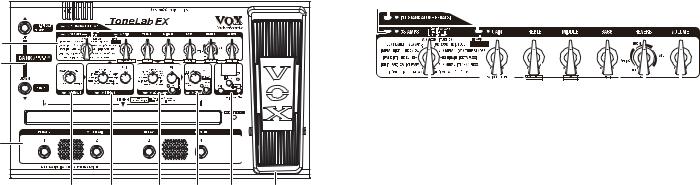
Top panel
1 |
|
|
|
|
|
2 |
|
|
|
|
|
3 |
|
|
|
|
|
4 |
5 |
6 |
7 |
8 |
9 |
1.Amp section
Here youʹll create settings for the amp model and stand alone pedal.
For details on each effect, refer to “Amp models” (p. 15) and “stand alone pedals” (p. 22).
NOTE: You cannot use the amp model and stand alone pedal simultaneously. If you turn one of them on, the other will turn off.
a b |
c |
|
|
|
|
|
|
|
|
|
|
|
|
|
|
|
||||||
|
|
|
|
|
|
|
|
|
|
|
|
|
|
|
|
|
|
|
|
|
|
|
|
|
|
|
|
|
|
|
|
|
|
|
|
|
|
|
|
|
|
|
|
|
|
|
|
|
|
|
|
|
|
|
|
|
|
|
|
|
|
|
|
|
|
|
|
|
|
|
|
|
|
|
|
|
|
|
|
|
|
|
|
|
|
|
|
|
|
|
|
|
|
|
|
|
|
|
|
|
|
|
|
|
|
|
|
|
|
|
|
|
|
|
|
|
|
|
|
|
|
|
|
|
|
|
|
|
|
|
|
|
|
|
|
|
|
|
|
|
|
|
|
|
|
|
|
|
|
|
|
|
|
|
|
|
|
|
|
|
|
|
|
|
|
|
|
|
|
|
|
|
|
|
|
|
|
|
|
|
|
|
|
d |
e |
f |
g |
h |
a.AMPS bank select switch and LED
Use this to switch the bank, or to turn the amp model on/off.
Each time you press the switch, the bank will cycle between STANDARD, SPECIAL, CUSTOM, STANDARD...
The color of the LED will indicate the bank that’s selected.
•STANDARD: green
•SPECIAL: orange
•CUSTOM: red
The LED will be lit up if the amp model is on. By holding down this switch for about one second you can switch the amp model on/off.
2
b.STAND ALONE PEDALS switch and LED
Use this to turn the stand alone pedal on/off.
The LED will be lit up if the stand alone pedal is on.
c.CABINET ON/OFF switch and LED
This turns the cabinet model on/off. The LED will be lit if the cabinet model is on.
By entering the OPTION parameter setting mode you can set parameters for the cabinet model.
The OPTION parameter setting mode
To enter the OPTION parameter setting mode, hold down the CABINET ON/OFF switch for about one second. You’ll be in The OPTION parameter setting mode, and the LED will blink.
The OPTION parameter setting mode lets you adjust the fol lowing settings.
•GAIN control: cabinet model (CABINET SELECT)
•TREBLE control: presence (PRESENCE)
•MIDDLE control: noise reduction (NR)
•BASS control: Total Equalizer High (EQ HI)
•REVERB control: Total Equalizer Low (EQ LO)
•VOLUME control: Trim (TRIM)
To return to the previous operation, press the CABINET ON/ OFF switch or the EXIT/TUNE switch.
NOTE: Total Equalizer is enabled only when the AMP/LINE switch is set to LINE.
NOTE: Presence is effective only when the amp model or the stand alone pedal is turned on.
d.AMPS/STAND ALONE PEDALS selector
This selects the amp model or the stand alone pedal.
The type you select will determine the response of the gain circuit and tone controls, and the order in which they are located in the circuit.
If the amp model and stand alone pedals are turned off, rotating this selector will turn the amp model or stand alone pedal on.
e.GAIN control
This adjusts the gain of the selected amp model or stand alone pedal.
In the OPTION parameter setting mode, this control selects the cabinet model. If the cabinet model is turned off, turning this control in the OPTION parameter setting mode will turn the cabinet model on.
f.TREBLE, MIDDLE, BASS controls
These adjust the tone of the high, mid, and low frequency ranges. The way these controls affect the tone will depend on the model you’ve selected.
NOTE: Depending on the selected amp model, there may be almost no sound if you turn all three of these controls to the far left.
In the OPTION parameter setting mode, the TREBLE control adjusts the presence, the MIDDLE control adjusts the noise reduction, and the BASS control enables you to adjust the Total Equalizer High.
g.REVERB knob
Depending on the position of the knob, this selects the reverb type (SPRING, ROOM, or HALL), and adjusts the amount of
3
reverb in the mix. If you turn the knob all the way to the left, the reverb effect will be turned off.
In the OPTION parameter setting mode, this control knob enables you to adjust the Total Equalizer Low.
For details on each effect, refer to “Reverb types” (p. 29)
h.VOLUME control
This adjusts the volume of the program.
In the OPTION parameter setting mode, it enables you to select Trim.
HINT: You can adjust the volume of the program even when the amp model is turned off.
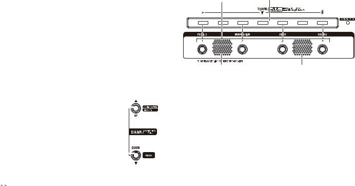
2.Bank select section
a. BANK UP/DOWN pedals |
a |
|
|
|
In program select mode, these pedals enable |
|
|
|
|
|
|
|||
you to select a program bank (p. 10, “Trying |
|
|
|
|
out the ToneLab EX”). |
|
|
|
|
Pressing the BANK UP pedal will increment |
|
|
|
|
the bank by one, and pressing the DOWN |
|
|
|
|
|
|
|
|
|
pedal will decrease the bank by one. |
a |
|
|
|
|
|
|
||
The bank number will be displayed in the |
|
|
|
|
|
|
|||
Bank/Value display. |
|
|
|
|
If you press the UP and DOWN pedals |
|
|
|
|
simultaneously for about one second, the |
|
|
|
|
“ 
 ” indicator will appear on the Bank/Value display, and the unit will enter Stomp Box Mode. In Stomp Box Mode, these pedals turn on or off the amp/stand alone pedal and the effect assigned to pedal 1 individually (p. 11, “Stomp Box Mode”).
4
3. Program Select/Tuner/Stereo Speakers section
a |
b |
c |
c |
a.Program 1–4 pedals and LED
In program select mode, these pedals enable you to select a pro gram from a bank (p. 10, “Trying out the ToneLab EX”). If you select a program, a program LED that corresponds to the selected program will be lit up red. (Program 1–4 LEDs are located above the program 1–4 pedals and indicate the tuning status.)
HINT: You can set the delay time using the program 1–4 ped als. In this case, the interval at which you tap twice on a program pedal (that corresponds to the selected pro gram) will be assigned as the delay time.
HINT: If you press and hold down the program pedal that corre sponds to the current program for about one second, all ef fects will be bypassed and youʹll be able to use the tuner. If you hold down the program pedal for about two seconds, youʹll be able to use the tuner with the sound muted.
In Stomp Box Mode, these pedals turn on or off the pedal 2 effect, modulation effect, delay effect, and reverb effect individ ually. When an effect is turned on, the corresponding program 1–4 pedal LED will be lit up red (p. 11, “Stomp Box Mode”).
b.TUNER LED
These lights are used for tuning (p. 29, “Tuner”).
When you’re using the tuner, the LEDs will indicate the tun ing status.
c.Stereo speakers
You can listen to the sound output from the built in stereo speakers. To adjust the volume level, use the SPEAKER LEVEL control on the rear panel (p. 8).
NOTE: The speakers will be muted when a cable is connected to the OUTPUT/PHONES jack.
NOTE: Some programs (especially those with an emphasized low range) may cause the sound from the speakers to be distorted or noisy. In such a case, adjust the volume level using the SPEAKER LEVEL control.
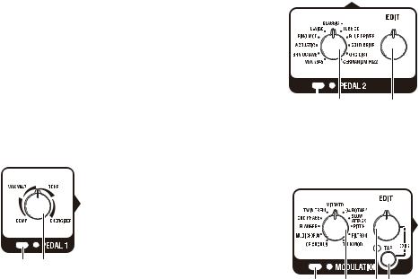
4.Pedal 1 section
Here you can adjust the settings for the pedal 1 effects.
For details on each effect, refer to “Pedal 1” (p. 23)
a. PEDAL 1 ON/OFF switch and LED |
|
This turns the pedal 1 effect on/off. |
a b |
The LED will be lit if the pedal 1 effect is on. |
b.PEDAL 1 knob
Rotating this knob enables you to select the pedal 1 effect type and adjusts the effect parameters assigned to each effect. If the pedal 1 effect is turned off, rotating this selector will turn the pedal 1 effect on.
5.Pedal 2 section
Here you can adjust the settings for the pedal 2 effects. For details on each effect, refer to “Pedal 2” (p. 24).
a. PEDAL 2 ON/OFF switch
and LED
This turns the pedal 2 effect on/off. The LED will be lit if the pedal 2 effect is on.
b. PEDAL 2 selector |
|
|
|
This selects the pedal 2 type. |
|
|
|
|
|
|
|
If the pedal 2 effect is turned |
|
|
c |
a b |
|||
off, turning this selector will |
|
|
|
turn the pedal 2 effect on.
c.EDIT knob
This adjusts the parameters of each effect.
6.Modulation section
Here you can adjust the set tings for the modulation effect. For details on each effect, refer to “Modulation” (p. 25).
a. MODULATION ON/OFF switch |
|
|
and LED |
b |
c d |
a |
This switch turns the modula tion effect on/off.
The LED will be lit if the effect is on.
5
b.MODULATION selector
This selects the modulation type.
If the modulation effect is off, rotating this selector will turn the modulation effect on.
c.EDIT knob
This adjusts the parameters of each effect.
You can use this knob to adjust two different parameters, EDIT 1 or EDIT 2. The specific parameters that are adjusted will depend on the selected effect. For details, refer to “Modulation” (p. 25).
•EDIT 1: turn the EDIT knob
•EDIT 2: hold down the TAP switch and turn the EDIT knob
d.TAP switch and LED
This is used to set the speed of the modulation effect. The interval used to press the TAP switch twice will be assigned as the effects modulation speed.
The LED will blink to indicate the specified speed.
HINT: To set a precise speed that matches the tempo of a song, press the TAP switch several times in rhythm with the song.
•If you’ve selected PITCH, the pitch setting will change each time you press the TAP switch.
•If you’ve selected FILTRON, the envelope up/down setting will change each time you press the TAP switch. The LED will light up if Up is selected.
•f youʹve selected TALK MOD, the vocal character type (1 or 2) setting will change each time you press the TAP switch. If type 2 is selected, the LED will light up.
You can edit parameters such as SPEED or PITCH by holding down the TAP switch and turning the EDIT knob (EDIT 2).
6 For details, refer to “Modulation” (p. 25).
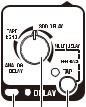
7.Delay section
Here you can adjust the settings for the delay effect.
For details on each effect, refer to “Delay types” (p. 28)
a. DELAY ON/OFF switch and LED |
|
This switch turns the delay effect on/off. |
a b c |
The LED will be lit if the effect is on. |
b.DELAY knob
Rotating this knob enables you to select the delay type or adjust the delay level.
If the delay effect is turned off, rotating this selector will turn the delay effect on.
To adjust the feedback amount, rotate the DELAY knob while holding down the TAP switch.
c.TAP switch and LED
This is used to set the delay time of the delay effect. The inter val used to press the TAP switch twice will be assigned as the delay time.
The LED will blink to indicate the specified time.
NOTE: You can set the delay time using the program 1–4 ped als. In this case, the interval at which you tap twice on a program pedal (that corresponds to the selected pro gram) will be assigned as the delay time.
HINT: To set a precise time that matches the tempo of a song, press the TAP switch several times in rhythm with the song.
8.Setting/Display section
a.Bank/Value display
This display usually indicates a bank number. When youʹre using the tuner, it indicates a note name.
While you are selecting a bank, the bank number will blink.
a 


 d b
d b 


c |
e |
When you’re editing a parameter,
this shows the parameter value that you’re editing.
If the parameter value matches the original value, the decimal point segment in the lower right of the LED will momentarily light up (p. 13, “Parameter original value indication”).
In Stomp Box Mode, the“ 
 ” indicator will appear on the Bank/Value display (p. 11).
b.EXIT/TUNE switch
Press this if you decide to cancel an operation (such as saving a program). When the CABINET on/off switch LED, the Quick Assign LED, or the bank/value display are not blink ing, you can press this switch to use the tuner (p. 29, “Tuning procedure”).
By holding down this switch for about two seconds, you can activate the Key Lock function, which locks (disables) the operations of the switches, selectors, and knobs on the top panel. To deactivate this function, hold down the switch once again for about two seconds.
c.WRITE switch
Press this if you saved the sound you’ve edited (p. 15, “Sav ing a program”).
d. Quick Assign LED |
|
This will light when the Quick Assign function is available, |
|
and will blink when you’re specifying the variable range of |
|
the expression pedal. |
|
e. EXPRESSION switch |
|
This lets you specify the maximum value and minimum |
|
value of the parameter that’s assigned to the pedal. For |
|
details, refer to “Expression pedal minimum and maximum |
|
values” (p. 32). |
|
If the Quick Assign LED is lit, holding down this switch for |
|
approximately two seconds will assign a effect parameter to |
|
the expression pedal (p. 31, “Assigning a function to the |
|
expression pedal (Quick Assign)”). |
|
9.Expression pedal section |
|
a. EXPRESSION PEDAL LED |
|
This will light when the effect assigned |
|
to the expression pedal is on. |
|
b. Expression pedal |
|
This controls the function that’s assigned |
|
to the expression pedal (e.g., volume or |
a |
wah), or controls the parameter of some |
|
other effects. |
b |
If you firmly advance the expression pedal |
|
all the way forward, the effect assigned to |
|
the pedal will be switched on/off. |
|
NOTE: If volume is assigned to the expression pedal, advancing the pedal in this way will not turn off the volume pedal.
7
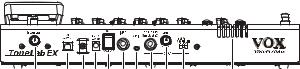
Rear panel
1 |
2 |
3 4 5 6 7 8 |
9 10 |
11 |
1.SPEAKER LEVEL knob
This adjusts the output level of the built in stereo speakers.
NOTE: The speakers will be muted when a cable is connected to the OUTPUT/PHONES jack.
2.USB connector (Type B)
If you use a commercially available USB cable to connect the ToneLab EX to your computer, you’ll be able to use librarian software on your computer to manage user programs, or use the ToneLab EX as a USB audio interface.
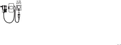
3.Cable hook
Wrap the cable of the AC adapter around this hook to prevent the AC adapter from being accidentally disconnected.
For details, refer to “Making connections” (p. 9).
4.DC 12V connector
Connect the included AC adapter here.
NOTE: The included AC adapter is only for use with the ToneLab EX. Using it with any other device may cause malfunctions, so you must never do so.
5.ON/STANDBY switch
This turns the power on or off (STANDBY).
6.INPUT connector
Connect your guitar cable here.
7.AUX IN jack
This is a stereo mini jack where you can connect the output (analog output) of an audio device.
You can connect a CD or MP3 player here, and play along on your guitar while listening to your favorite songs. To adjust the volume, use the controls of the connected device.
8.OUTPUT/PHONES jack
Connect your guitar amp, mixer, or headphones here. This jack will accommodate either stereo or monaural connections.
9.LEVEL knob
This adjusts the output level of the OUTPUT/PHONES jack.
10.AMP/LINE switch
The correct setting of this switch will depend on what is con nected to the OUTPUT/PHONES jack.
For details, refer to “Making connections” (p. 9).
11.Valve
The internal 12AX7 (ECC83) vacuum tube is located here.
NOTE: The vacuum tube may break if it is subjected to physi cal impact. Be careful not to subject the ToneLab EX to strong physical impact.
8
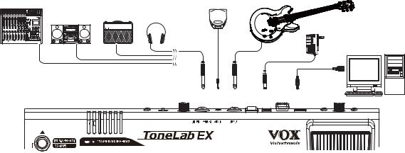
Making connections
Here’s how to make connections and start using your ToneLab EX.
Mixer, recorder, etc. |
CD, MP3 player, etc. |
Guitar |
Audio system |
Guitar amp Headphones |
|
VOX |
AC adapter
USB cable
OUTPUT/PHONES |
AUX |
INPUT |
DC12V |
USB |
|
IN |
|
|
|
Computer |
1.Set the AMP/LINE switch appropriately for the type of de vice you’ll be connecting to the OUTPUT/PHONES jack.
Set the AMP/LINE switch as follows.
AMP (VOX, F, M)
If you’re connecting a guitar amp, choose the VOX, F, or M setting. This setting will compensate the output from the amp model as necessary. However, compensation will not be applied if the amp model is off or the stand alone pedal is selected.
•VOX: Use this setting if the output is connected to an amp that has a distinctive mid range such as the AC30 open backed combo amp made by the VOX Corporation.
•F: Use this setting if the output is connected to a typical clean sounding US made open backed combo amp.
•M: Use this setting if the output is connected to a higher gain stack type amp such as a 4x12 closed back cabinet.
LINE
Use this setting if the output is connected to your guitar amp’s power amp, to an audio system, mixer, or recorder, or to headphones, or if the ToneLab EXʹs built in speakers are used. When LINE is selected, you can use Total Equal izer. Adjust the output sound in OPTION parameter set ting mode (p. 14, “Using Total Equalizer”).
9
2.Use a cable to connect the ToneLab EX’s OUTPUT/ PHONES jack to your guitar amp, mixer, or other device.
NOTE: Before connecting the ToneLab EX, lower the vol ume level of your guitar amp or mixer.
The OUTPUT/PHONES is equipped with a stereo output jack. Use a stereo (TRS) cable to enjoy listening to or re cording with your ToneLab EX in stereo.
If your amplifier or mixer has only mono inputs, you can purchase a cable that has a stereo plug on one end, and two mono plugs (Left and Right) on the other.
Connecting a mono cable to the OUTPUT/PHONES jack will only pick up the sound from Left channel.
3.Set the LEVEL knob and SPEAKER LEVEL knob on the rear panel to “0” by turning the knob all the way to the left (as seen from the rear panel).
4. Connect the plug end of the AC adapter (included) to the DC12V jack on the rear panel of the ToneLab EX, and the other end into an AC outlet.
Secure the AC adapter cable around the cable hook; this will reduce stress on the plug end of the adapter, and prevent it from disconnecting accidently.
5.Using a standard guitar cable, connect your guitar to the INPUT jack of the ToneLab EX
6.Make sure that the volume of your amp or mixer is turned down, and then set the ON/STANDBY switch on the ToneLab EX to the “ON” position.
7.Raise the volume controls of your amp or mixer to their normal levels, and use the LEVEL knob or SPEAKER LEVEL knob on the rear panel to adjust the volume to a suitable level.
NOTE: The ToneLab EX uses a vacuum tube, so it may take a few seconds for the vacuum tube to warm up, and for the ToneLab EX to produce sound.
Trying out the ToneLab EX
The ToneLab EX has a total of two hundred programs, con sisting of rewritable user programs (Banks 1–25 x 4) and pre set programs (Banks 26–50 x 4).
Performance modes
The ToneLab EX features two performance modes: Program Select mode enables you to select and play programs; Stomp Box mode enables you to turn on or off individual effects assigned in the selected program.
Switching between modes
Press both the BANK UP and BANK DOWN pedals simulta neously for one second.
Repeat this operation to toggle between Stomp Box mode and Program Select mode.
If the Bank/Value display indicates a bank number, Program Select mode is engaged. If the display indicates “ 

 ,” Stomp Box mode is engaged.
10
Loading...