

Volkswagen Jetta 2000, Jetta 1999, Golf 1999, Golf 2000, GTI 1999 Diagnostic Manual
...
Instrument panel, On Board Diagnostic (OBD) (through MY 1999)
Clock, correcting
Code Control Module
Consumption indicator, matching
Display group overview
Distance impulse number (K number), reading
Distance travelled (odometer) display, adapting
Fuel gauge (adaptation), checking
Language alternatives for drivers instructions, adapting
Locations of instrument panel senders and sensors
On Board Diagnostic, initiating
Output Diagnostic Test Mode
Read Measuring Value Block
Service interval display, resetting
Service interval, adapting data when changing the instrument panel
Instrument panel On Board Diagnostic (OBD) (from MY 2000)
Code Control Module
Consumption indicator, matching
Display group overview
Distance impulse number (K number), reading
Distance travelled (odometer) display, adapting
Fuel gauge (adaptation), checking
Instrument panel senders and sensors, locations
Language alternatives, adapting for drivers instructions
On Board Diagnostic, initiating
Output Diagnostic Test Mode
Read Measuring Value Block
Service interval data, adapting when changing the instrument panel
Service interval display, resetting
Diagnostic interface for databus
Code Control Module
Display group overview
Read Measuring Value Block
Anti
-theft immobilizer On Board Diagnostic (OBD)
Diagnostic Trouble Code (DTC) table
Emergency start function, activating without VAG 1551
Ignition keys, matching
Immobilizer On Board Diagnostic (OBD), initiating
Immobilizer, troubleshooting
Lost key procedure
Procedure after changing engine control module (Matching)
Procedure after changing instrument cluster (Matching)
Read Measuring Value Block
Volkswagen Jetta, Golf, GTI 1999, 2000
Electrical Equipment On Board Diagnostic (OBD)
01 On Board Diagnostic (OBD) (Page GR-01)
Volkswagen Technical Site - http://volkswagen.msk.ru

Volkswagen Jetta, Golf, GTI 1999, 2000
Electrical Equipment On Board Diagnostic (OBD)
Instrument panel, On Board Diagnostic (OBD) (through MY 1999) (Page 01-1)
Notes:
The instrument panel is installed in conjunction with vehicle equipment level, there are different
versions:
Lowline version with rev counter and digital clock or
Midline version with rev counter and multi-function indicator or
Highline version with rev counter, multi-function indicator and navigation display unit.
Notes when exchanging instrument panels
Instrument panels which do not have the function "Convenience anti-theft system" have a control
unit part number where the last number is a 0 (production to approx. 07.98).
Instrument panels which do have the function "Convenience anti-theft system" have a control unit
part number where the last number is a 1 (production from approx. 08.98).
If a instrument panel with the function "Convenience anti-theft system" is replaced, then for
vehicles with
Radio system Premium IV 05.98
the radio electronic anti-theft system must be reactivated.
Repair Manual, Radio, Telephone, Navigation , Repair Group 91

Volkswagen Jetta, Golf, GTI 1999, 2000
Electrical Equipment On Board Diagnostic (OBD)
Instrument panel, On Board Diagnostic (OBD) (through MY 1999) (Page 01-2)
The convenience anti-theft system is operative after first activation of electronic anti-theft system.
Notes on function of of convenience anti-theft system
Repair Manual, Radio, Telephone, Navigation , Repair Group 91
The instrument panel must not be dismantled.
If required the instrument panel is to be exchanged using normal exchange part
procedures.
Complete damage report form and return together with instrument panel.
Use original packaging only when returning items.
The odometer reading and the service interval display can be matched to the
exchange instrument panel using scan tool VAG 1551 Page 01-48.
The instrument panel is controlled via a microprocessor which is equipped with an extensive selfdiagnosis.
If faults occur in the sensors and components being monitored, they will be stored in the fault
memory together with an indication of the type of fault.

Volkswagen Jetta, Golf, GTI 1999, 2000
Electrical Equipment On Board Diagnostic (OBD)
Instrument panel, On Board Diagnostic (OBD) (through MY 1999) (Page 01-3)
A maximum of 4 faults can be stored simultaneously.
Sporadic faults are automatically cancelled if they are not repeated in next 50 engine starts.
The On Board Diagnostic must be initiated at the commencement of fault finding and the stored
information interrogated with the
Vehicle Diagnosis, Testing and Information system VAS 5051 or
Scan tool VAG 1551 or
Vehicle system tester VAG 1552.
Notes:
The following description deals only with the scan tool VAG 1551.
Measures for repairing commonly occurring faults on particular models
Technical Service Handbook
Volkswagen Jetta, Golf, GTI 1999, 2000
Electrical Equipment On Board Diagnostic (OBD)
Instrument panel, On Board Diagnostic (OBD) (through MY 1999) (Page 01-4)
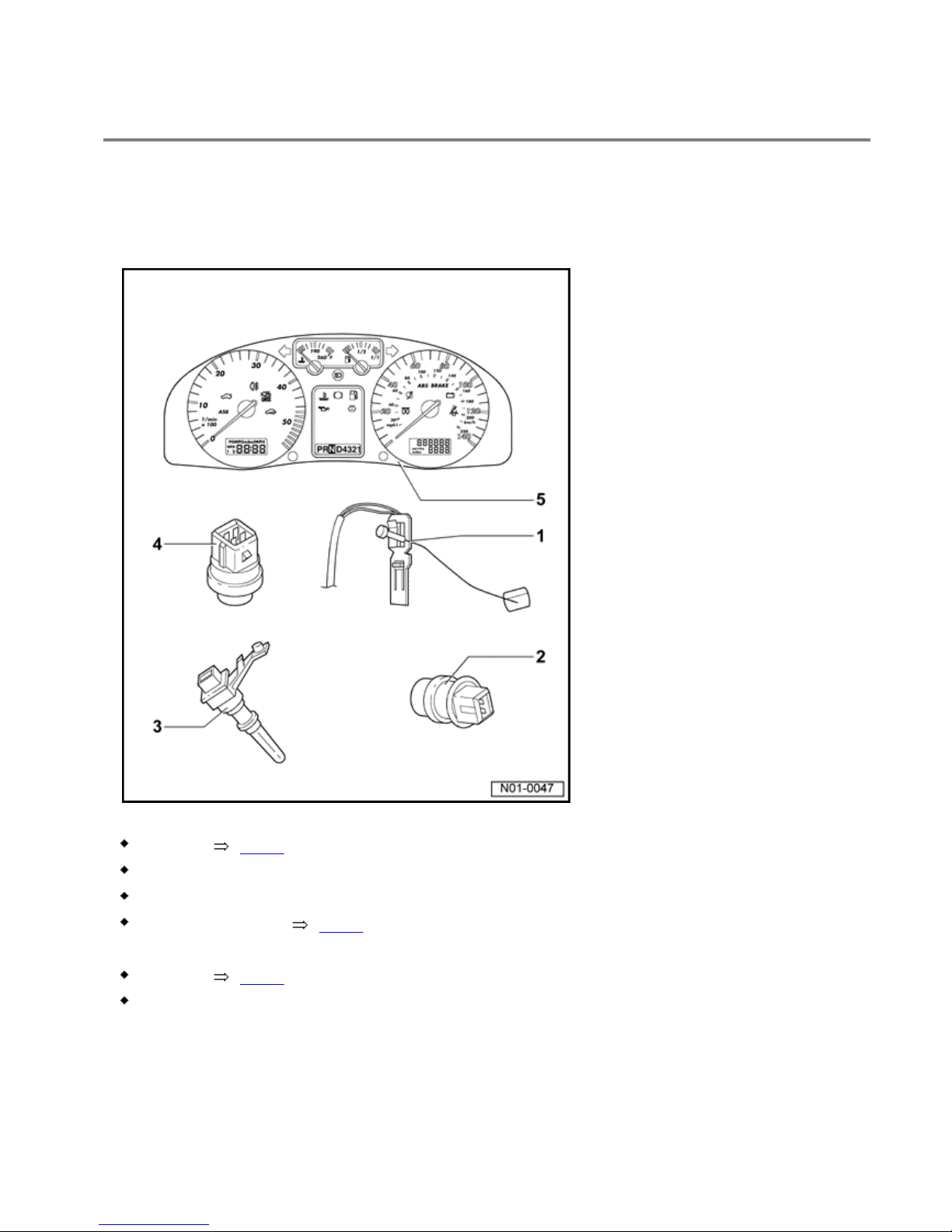
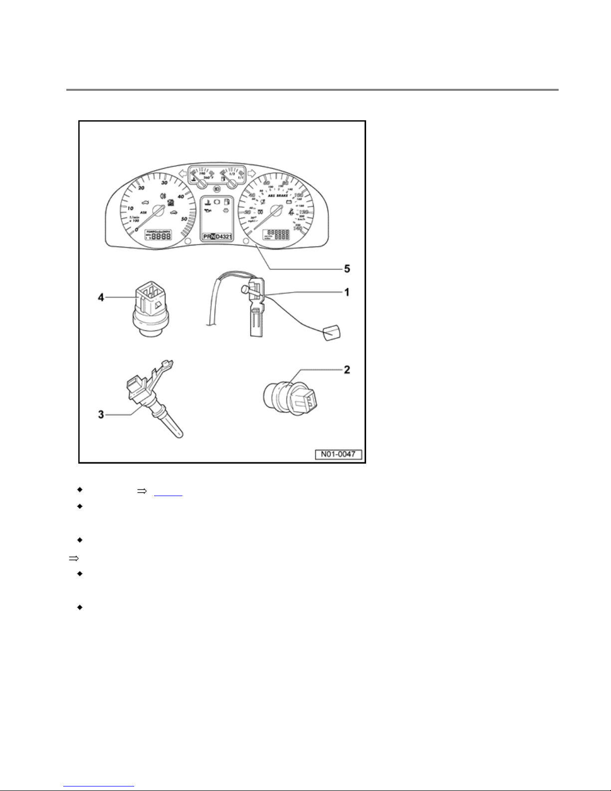
Locations of instrument panel senders and sensors
WARNING!
Disconnect battery earth strap before working on electrical system.
1 - Fuel gauge sender -G
Location Fig. 1
Monitored via self-diagnosis
An additional fuel gauge sender -G169- is installed in four-wheel drive vehicles
Location of -G169- Fig. 2
2 - Ambient temperature sender -G17
Location Fig. 3
Monitored via self-diagnosis
Volkswagen Jetta, Golf, GTI 1999, 2000
Electrical Equipment On Board Diagnostic (OBD)
Instrument panel, On Board Diagnostic (OBD) (through MY 1999) (Page 01-5)
3 - Speedometer sender -G22
Location Fig. 4
Monitored via self-diagnosis
4 - Coolant temperature sender -G2
Location depends on type of engine
Repair Manual, Fuel Injection & Ignition, Repair Group 24
Monitored via self-diagnosis
5 - Instrument panel -K
Monitored via self-diagnosis
Volkswagen Jetta, Golf, GTI 1999, 2000
Electrical Equipment On Board Diagnostic (OBD)
Instrument panel, On Board Diagnostic (OBD) (through MY 1999) (Page 01-6)
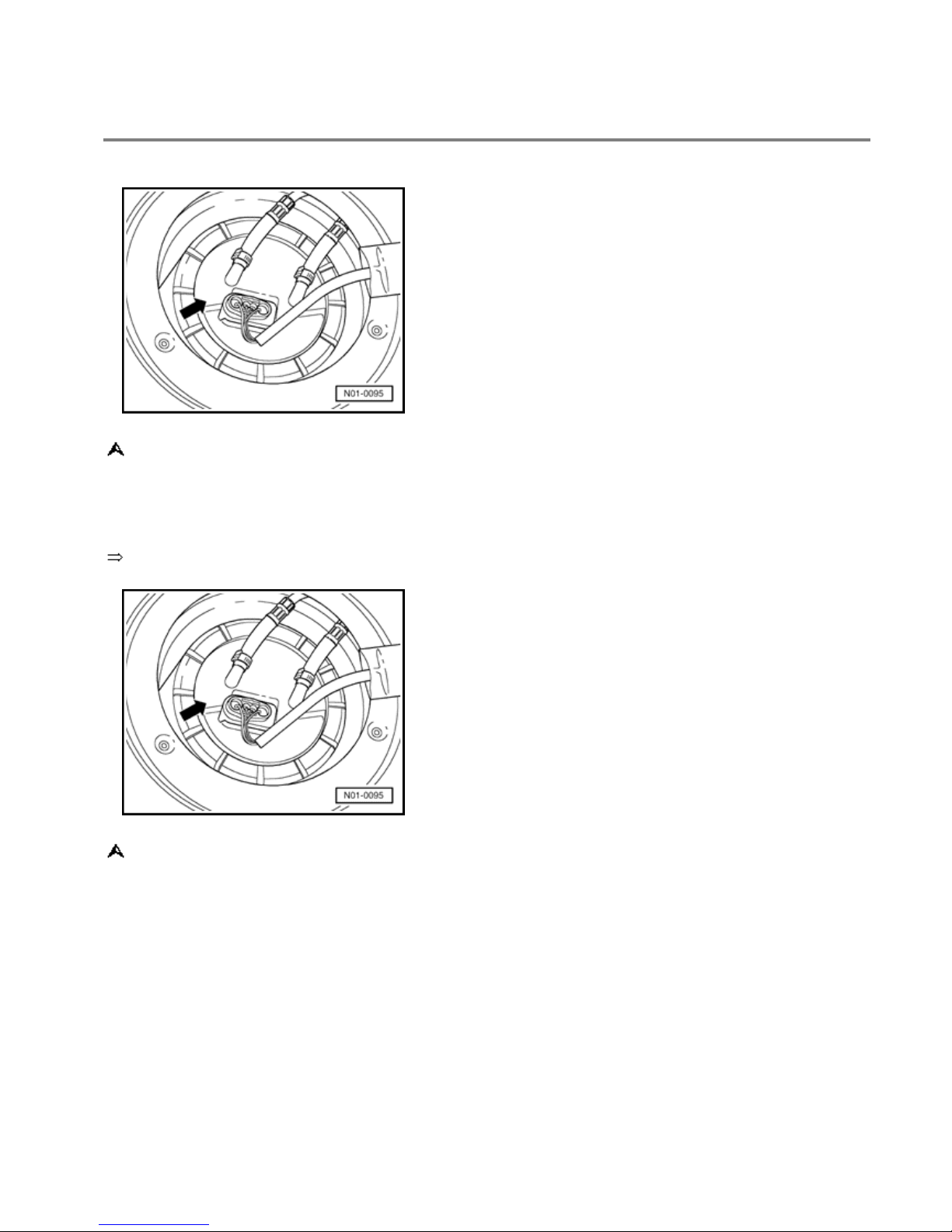
Fig. 1 Fuel gauge sender -G
The fuel gauge sender -G- is located in the fuel tank on the fuel delivery unit -arrow-.
Removing and installing fuel delivery unit
Repair Manual, Engine Mechanical, Repair Group 20
Fig. 2 Additional fuel gauge sender -G169- in four-wheel drive vehicles
In addition to the above mentioned sender -G- there is another sender -G169- in the vehicle
which is located on the left-hand side under the rear seat.

Volkswagen Jetta, Golf, GTI 1999, 2000
Electrical Equipment On Board Diagnostic (OBD)
Instrument panel, On Board Diagnostic (OBD) (through MY 1999) (Page 01-7)
Fig. 3 Ambient temperature sender -G17
The ambient temperature sender -G17- is located on left of front bumper behind the outer air
grille.
Unclip air grille to remove sender.
Repair Manual, Body-Exterior, Repair Group 63
Fig. 4 Speedometer sender -G22
The speedometer sender -arrow- is located in the area of the left-hand drive shaft flange on
manual and automatic gearbox vehicles.
Volkswagen Jetta, Golf, GTI 1999, 2000
Electrical Equipment On Board Diagnostic (OBD)
Instrument panel, On Board Diagnostic (OBD) (through MY 1999) (Page 01-8)
On Board Diagnostic, initiating
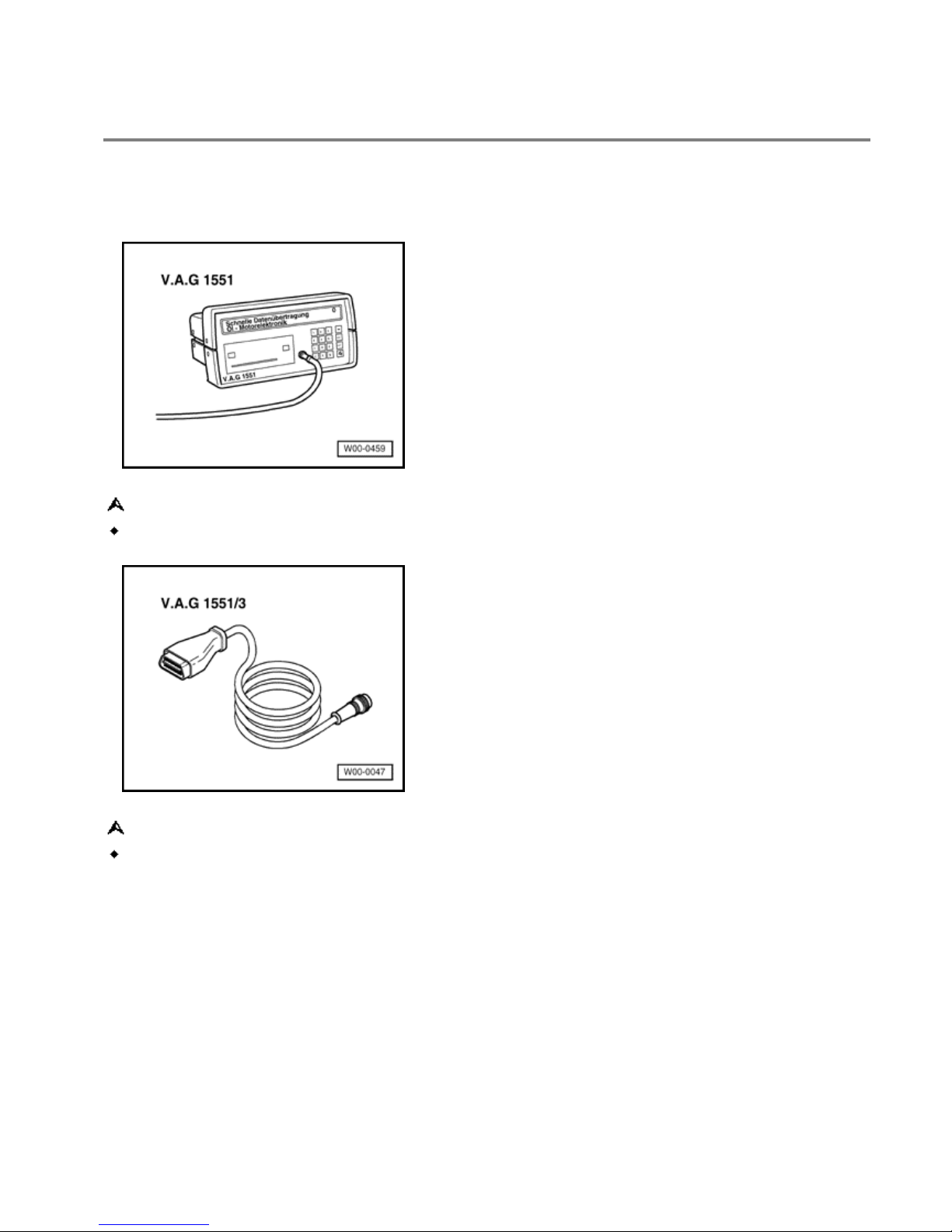
Special tools, testers, measuring units and auxiliary items required
Scan tool VAG 1551 or vehicle system tester VAG 1552.
VAG 1551/3 or 1551/3A adapter cable
Volkswagen Jetta, Golf, GTI 1999, 2000
Electrical Equipment On Board Diagnostic (OBD)
Instrument panel, On Board Diagnostic (OBD) (through MY 1999) (Page 01-9)
Connecting scan tool VAG 1551 and selecting functions (Interrogating unit version)
Check prerequisites:
All fuses according to current flow diagram OK.
Supply voltage OK. (at least 9.0 V).
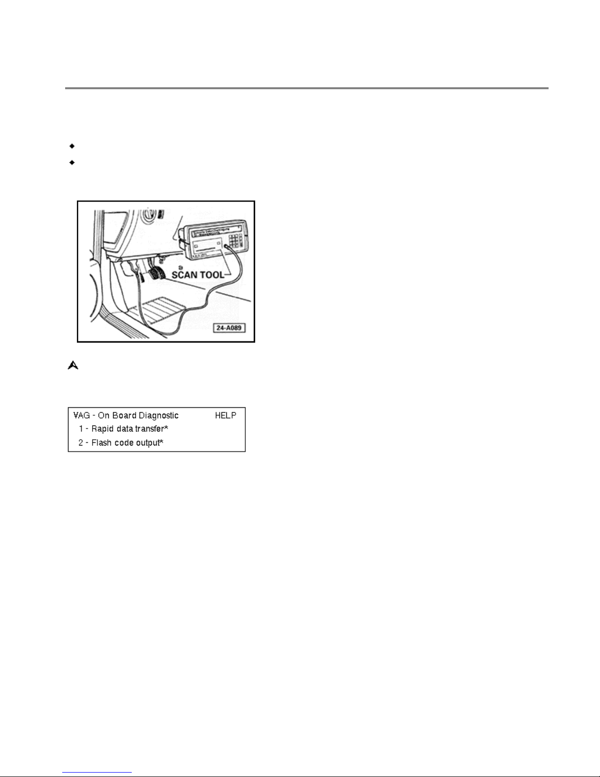
Connect scan tool using cable VAG 1551/3 as follows:
- Connect cable VAG 1551/3 to diagnosis connector located below dash to left of
steering column
Indicated on display:
* Appears alternately
Volkswagen Jetta, Golf, GTI 1999, 2000
Electrical Equipment On Board Diagnostic (OBD)
Instrument panel, On Board Diagnostic (OBD) (through MY 1999) (Page 01-10)
Notes:
If the display remains blank, check VAG 1551 voltage supply according to current
flow diagram.
Electrical Wiring Diagrams Troubleshooting & Component Locations binder
Additional operating instructions can be called up with the scan tool HELP key.
The key serves to advance the programme sequence.
In the operating mode 1 "Rapid data transfer" the function 00 "Automatic test
sequence" can be carried out. Then all vehicle control units will be interrogated
automatically.
- Switch on ignition.
- Switch on printer with the Print key (indicator lamp in key lights up).
- Press key 1 for "Rapid data transfer" mode.
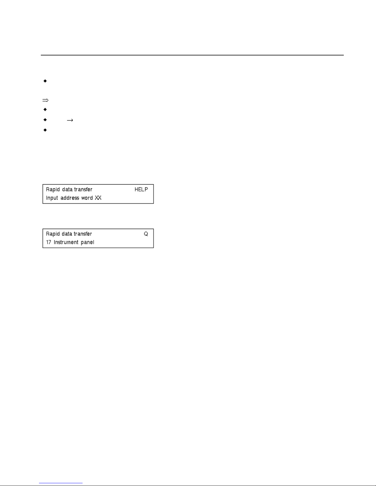
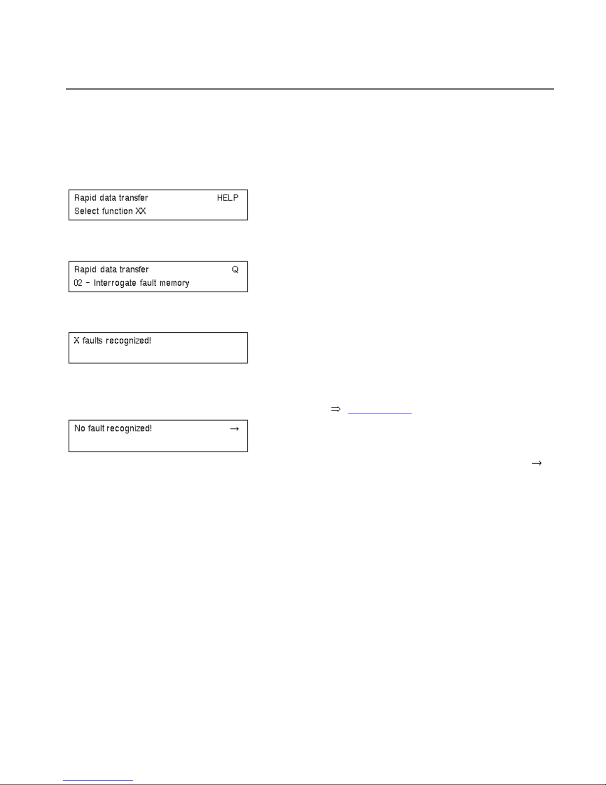
Indicated on display:
- Press keys 1 and 7. "17" enters the address word "Instrument panel".
Indicated on display:
- Confirm entry with Q key.
Volkswagen Jetta, Golf, GTI 1999, 2000
Electrical Equipment On Board Diagnostic (OBD)
Instrument panel, On Board Diagnostic (OBD) (through MY 1999) (Page 01-11)
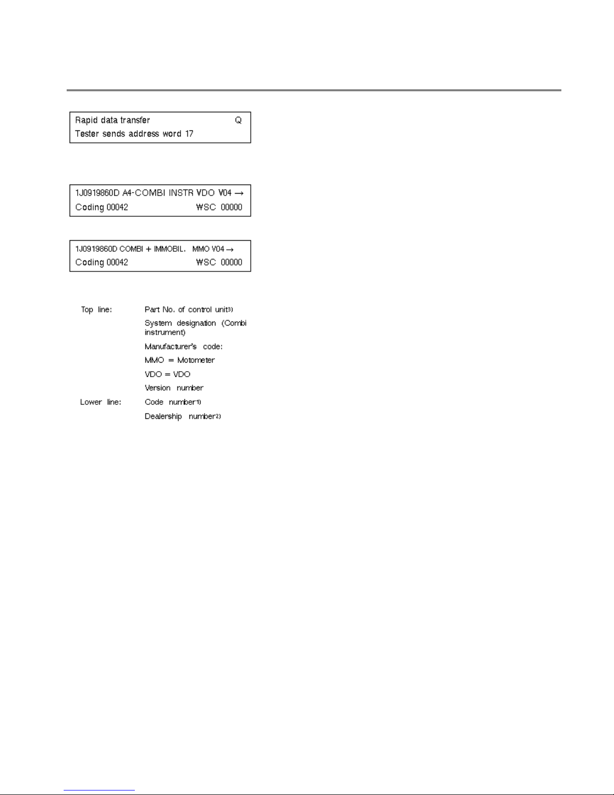
Indicated on display:
Interrogate control unit version
Indicated on display for instrument panel with manufacturer's code VDO:
Indicated on display for instrument panel with manufacturer's code MMO:
1- Dependent on engine, gearbox and additional equipment
2- Will be automatically stored in the control unit when entering the system, but not
when Code Control Modules which have been used.
3- Instrument panels which do not have the function "Convenience anti-theft system"
have a control unit part number where the last number is a 0 (production to approx.
07.98).

Volkswagen Jetta, Golf, GTI 1999, 2000
Electrical Equipment On Board Diagnostic (OBD)
Instrument panel, On Board Diagnostic (OBD) (through MY 1999) (Page 01-12)
Instrument panels which do have the function "Convenience anti-theft system" have a control unit
part number where the last number is a 1 (production from approx. 08.98).
If a instrument panel with the function "Convenience anti-theft system" is replaced, then for
vehicles with
Radio system Premium IV 05.98
the radio electronic anti-theft system must be reactivated.
Repair Manual, Radio, Telephone, Navigation Repair Group 91
The convenience anti-theft system is operative after first activation of electronic anti-theft system.
Notes on function of of convenience anti-theft system
Repair Manual,
Radio, Telephone, Navigation Repair Group 91

Volkswagen Jetta, Golf, GTI 1999, 2000
Electrical Equipment On Board Diagnostic (OBD)
Instrument panel, On Board Diagnostic (OBD) (through MY 1999) (Page 01-13)
Indicated on display:
Motometer instrument panels are identified by IMMO-IDENTNO: VWZ6 . . ..
VDO instrument panels are identified by IMMO-IDENTNO: VWZ7 . . ..
Will be indicated on display:
- By pressing the "HELP" key a list of possible fault causes is printed out.
- After repairing faults again enter address word 17 for instrument panel and confirm
with Q.
Indicated on display:
- Press key.
Indicated on display:
- Press key.
Indicated on display:
- After the HELP key is pressed, a list of the possible functions is printed out.
Volkswagen Jetta, Golf, GTI 1999, 2000
Electrical Equipment On Board Diagnostic (OBD)
Instrument panel, On Board Diagnostic (OBD) (through MY 1999) (Page 01-14)
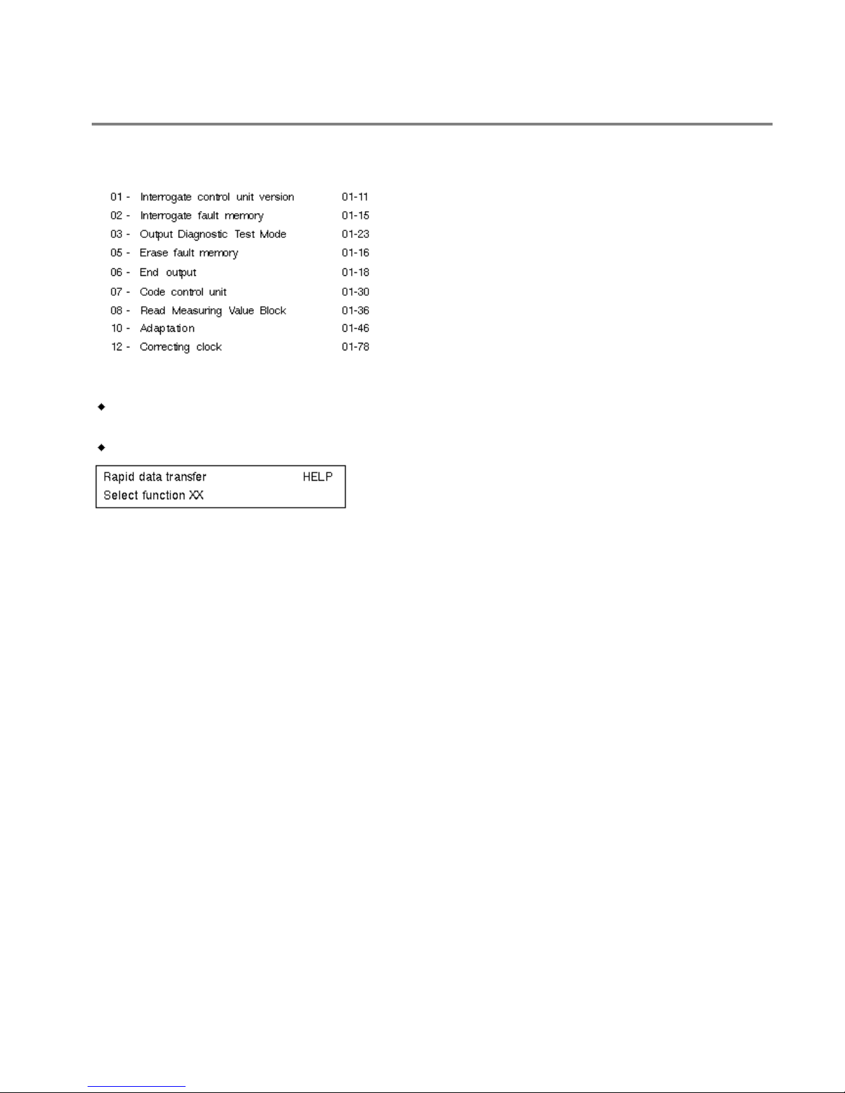
List of selectable functions
Notes:
Do not select further functions, which can be printed out after pressing the HELP
key.
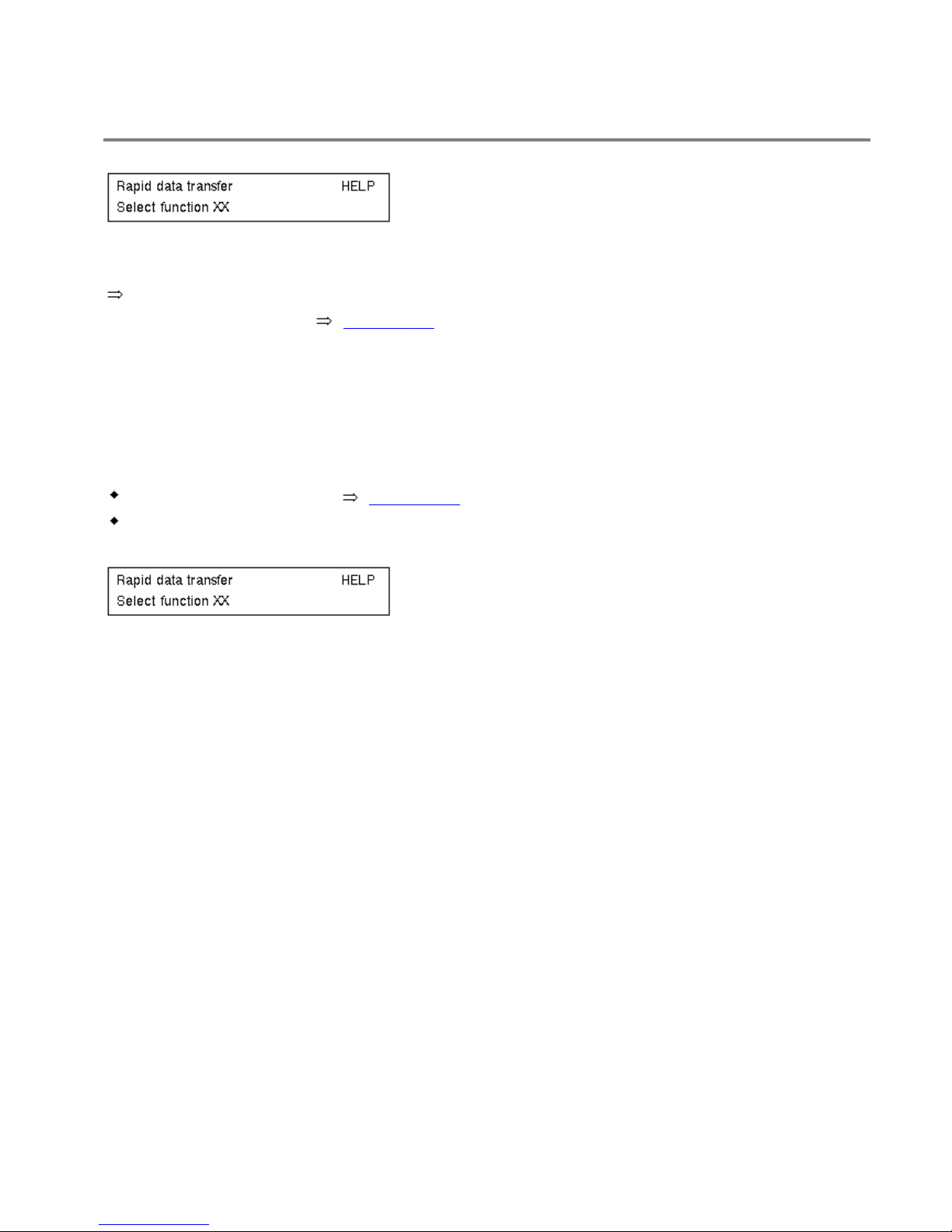
After the function is completed the VAG 1551 returns to the following start position:
Indicated on display:
Volkswagen Jetta, Golf, GTI 1999, 2000
Electrical Equipment On Board Diagnostic (OBD)
Instrument panel, On Board Diagnostic (OBD) (through MY 1999) (Page 01-15)
Interrogating fault memory
Notes:
The displayed fault information is not constantly up-dated, but only when initiating the selfdiagnosis or with the function 05 "Erase fault memory".
- Switch on printer with the Print key (indicator lamp in key lights up).
Indicated on display:
- Press keys 0 and 2. (The function "Interrogate fault memory" is selected with 02.)
Indicated on display:
- Confirm entry with key Q.
The number of stored faults appears in the display.
The stored faults are displayed and printed out one after another.
- Enter fault table at fault printed out and repair fault Page 01-178.
If "No fault recognized" is displayed the programme will return to the start point after pressing
key.
Volkswagen Jetta, Golf, GTI 1999, 2000
Electrical Equipment On Board Diagnostic (OBD)
Instrument panel, On Board Diagnostic (OBD) (through MY 1999) (Page 01-16)
Indicated on display:
If something else is displayed:
Scan tool operating instructions
- End output (function 06) Page 01-18.
- Switch off ignition and separate diagnostic connections.
Erasing fault memory
Notes:
After erasing the fault memory its contents will automatically be indicated. If the fault memory
cannot be erased, again interrogate fault memory and repair faults.
Prerequisites
Fault memory interrogated Page 01-15.
All faults repaired.
After fault memory has been successfully interrogated:
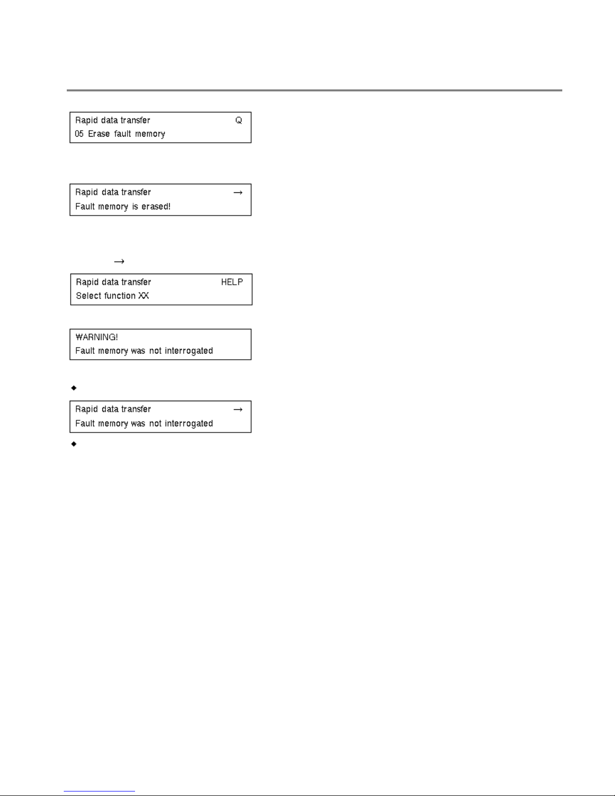
Indicated on display:
- Press keys 0 and 5. (05 selects the "Erase fault memory" function.)
Volkswagen Jetta, Golf, GTI 1999, 2000
Electrical Equipment On Board Diagnostic (OBD)
Instrument panel, On Board Diagnostic (OBD) (through MY 1999) (Page 01-17)
Indicated on display:
- Confirm entry with key Q.
Indicated on display:
The fault memory is now erased.
- Press key.
Indicated on display:
Notes:
If this appears in the display, the test sequence is faulty.
If this appears in the display, the test sequence is faulty.
Adhere exactly to test sequence: First interrogate fault memory, if necessary repair faults, then
erase.
Volkswagen Jetta, Golf, GTI 1999, 2000
Electrical Equipment On Board Diagnostic (OBD)
Instrument panel, On Board Diagnostic (OBD) (through MY 1999) (Page 01-18)
Ending output
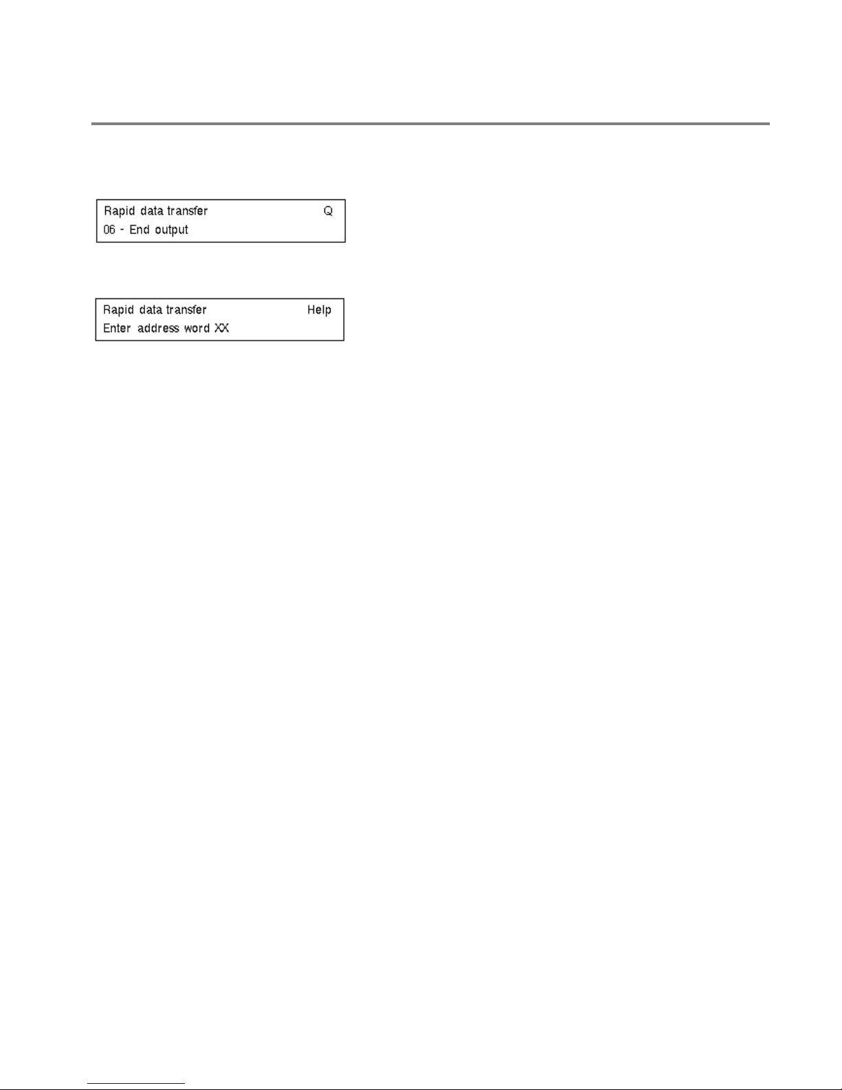
- Press keys 0 and 6. (The function "End output" is selected with 06.)
Indicated on display:
- Confirm entry with key Q.
Indicated on display:
- Switch off ignition.
- Disconnect scan tool VAG 1551.
Volkswagen Jetta, Golf, GTI 1999, 2000
Electrical Equipment On Board Diagnostic (OBD)
Instrument panel, On Board Diagnostic (OBD) (through MY 1999) (Page 01-19)
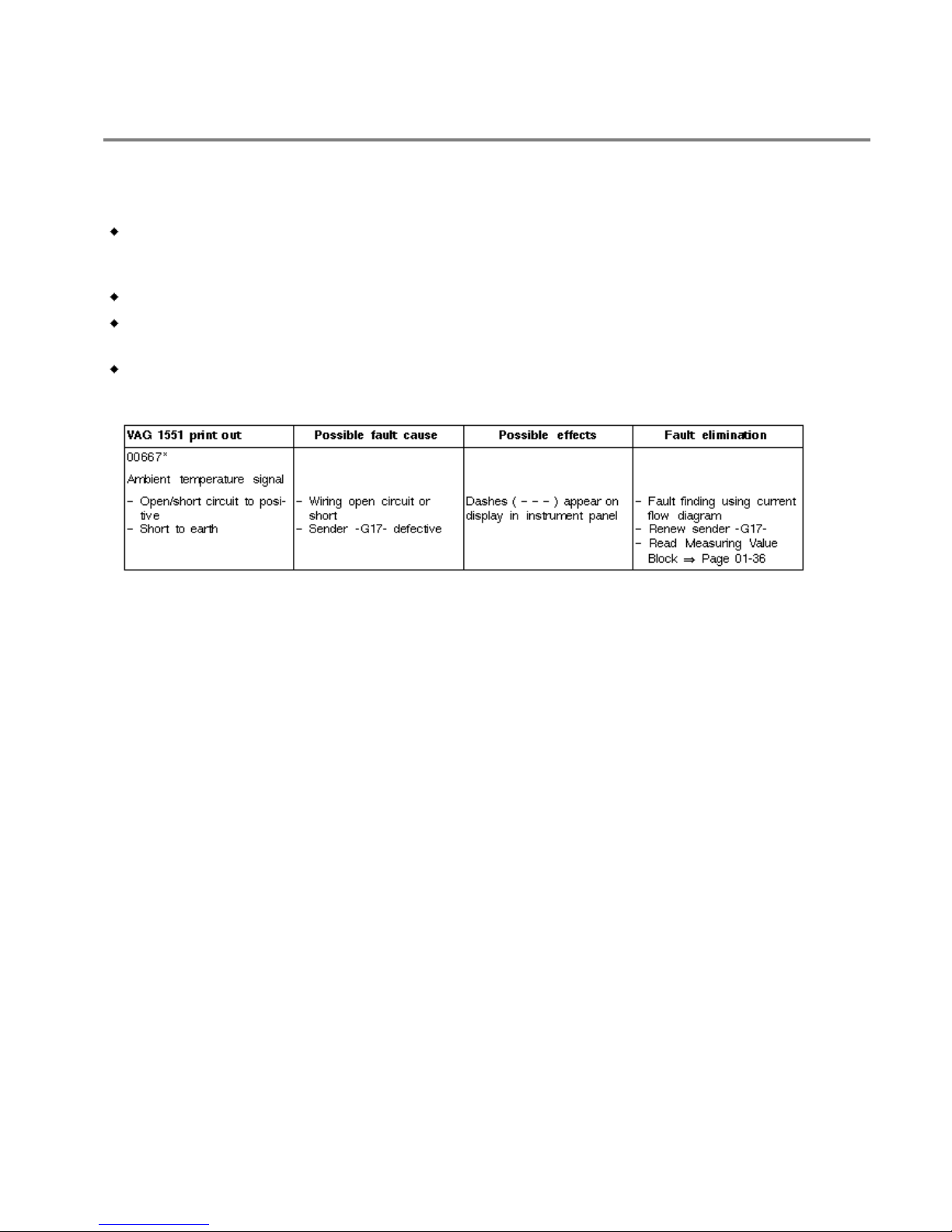
Fault table
Notes:
The following table lists all the faults, with the corresponding 5 digit code numbers,
that can be recognized by the instrument panel control unit -J285- and printed out by
the VAG 1551.
Fault codes appear only on print-out.
Before replacing components, check the wiring and connections to these
components as well as the earth connections, according to current flow diagram.
When repair has been carried out, the fault memory must always be interrogated
again with the scan tool VAG 1551 and erased.
*Not for vehicles with Climatronic: A fault entry is made when the fault has been registered
continuously for at least 60 seconds.
Volkswagen Jetta, Golf, GTI 1999, 2000
Electrical Equipment On Board Diagnostic (OBD)
Instrument panel, On Board Diagnostic (OBD) (through MY 1999) (Page 01-20)
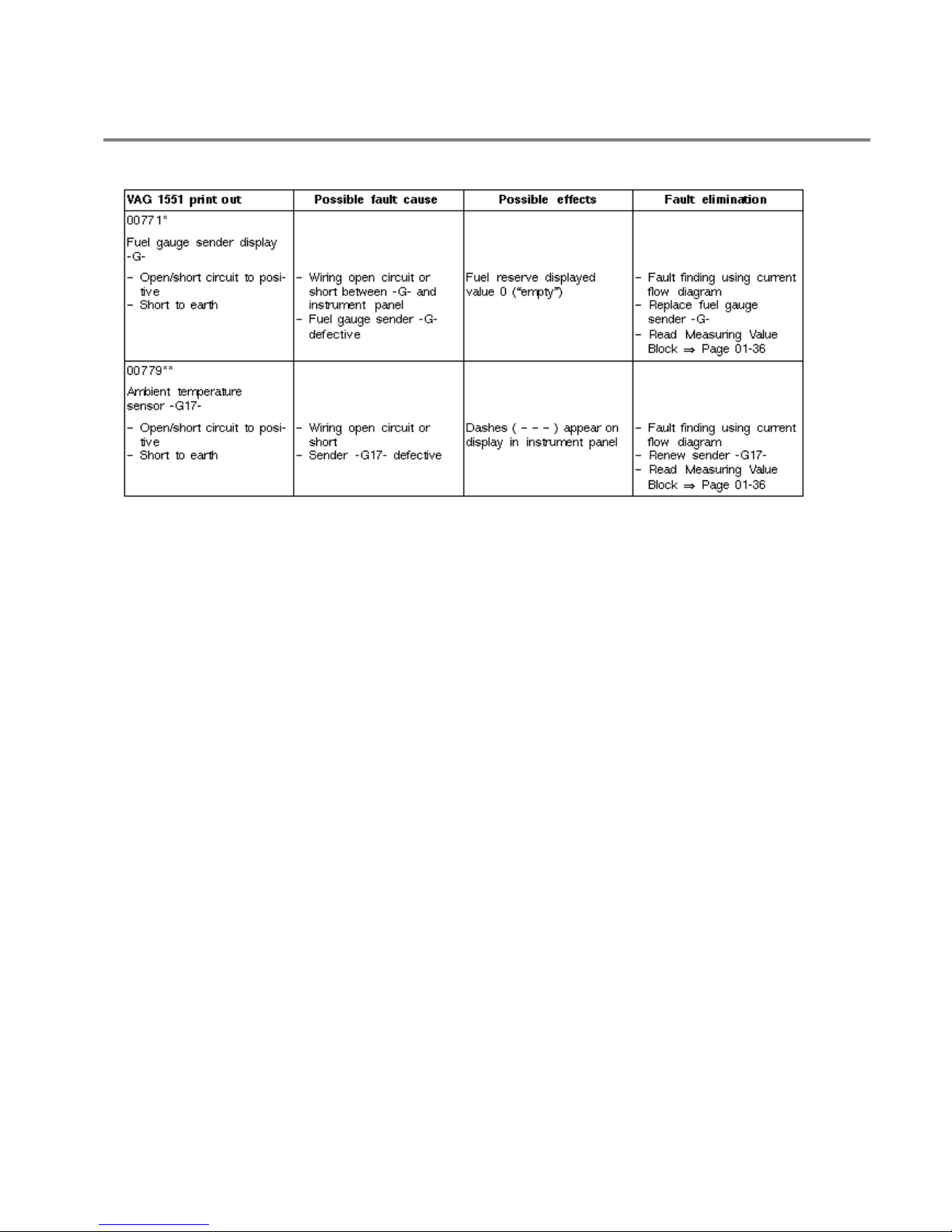
* A fault entry is made when the fault has been registered continuously for at least 20 seconds.
** For vehicles with a multi-function indicator but not with Climatronic

Volkswagen Jetta, Golf, GTI 1999, 2000
Electrical Equipment On Board Diagnostic (OBD)
Instrument panel, On Board Diagnostic (OBD) (through MY 1999) (Page 01-21)
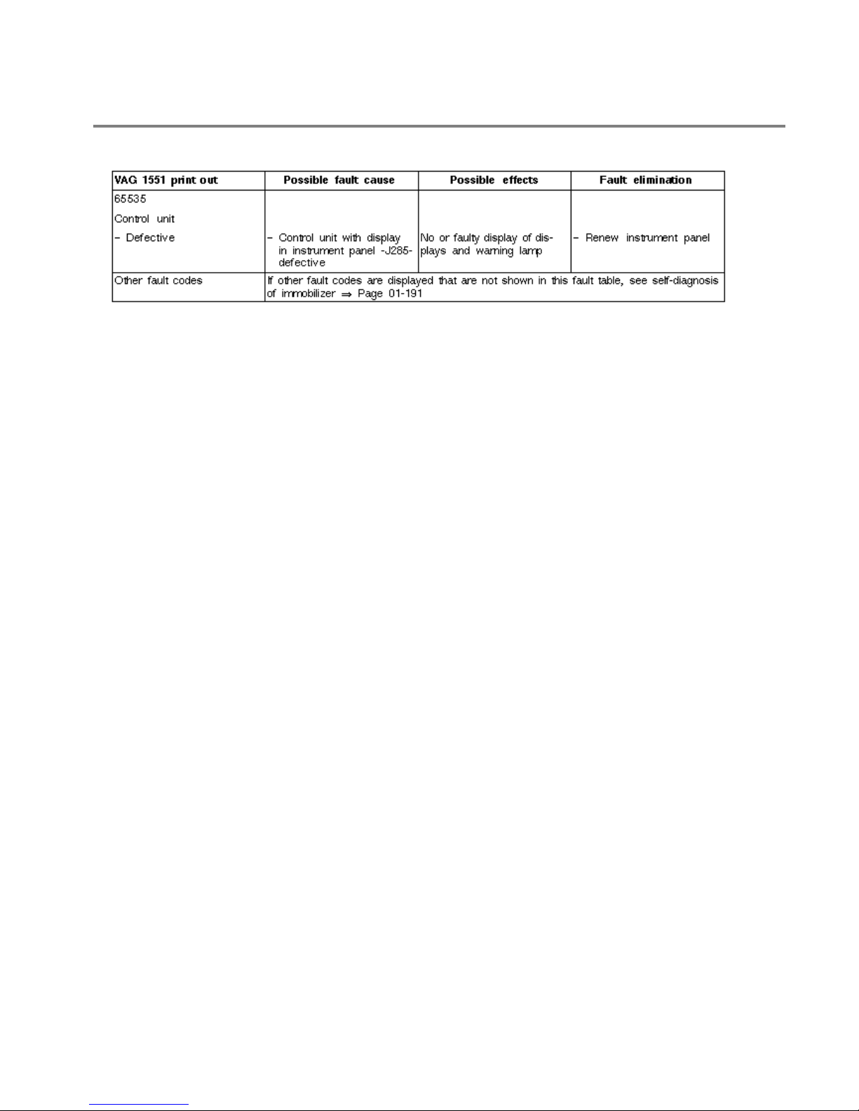
* A fault entry "Open circuit/short to positive" is made after the engine has been running for 30
minutes and the fault is recognized.
** Vehicles with Radio/Navigation system and Highline instrument panel only.
Volkswagen Jetta, Golf, GTI 1999, 2000
Electrical Equipment On Board Diagnostic (OBD)
Instrument panel, On Board Diagnostic (OBD) (through MY 1999) (Page 01-22)

Volkswagen Jetta, Golf, GTI 1999, 2000
Electrical Equipment On Board Diagnostic (OBD)
Instrument panel, On Board Diagnostic (OBD) (through MY 1999) (Page 01-23)
Output Diagnostic Test Mode
The Output Diagnostic Test Mode is part of the electrical check. The following components can be
checked via the Output Diagnostic Test Mode:
Speedometer
Rev counter
Coolant temperature gauge
Fuel gauge
Brake system warning lamp
Seat belt warning lamp (when activated using code)
Buzzer/Gong
Displays (odometer, multi-function indicator or digital clock, selector lever position
display for automatic gearboxes)
On Lowline and Midline instrument panels the following can additionally be checked
Coolant temperature/coolant shortage indicator warning lamp
Brake pad wear indicator warning lamp (when activated using code)

Volkswagen Jetta, Golf, GTI 1999, 2000
Electrical Equipment On Board Diagnostic (OBD)
Instrument panel, On Board Diagnostic (OBD) (through MY 1999) (Page 01-24)
Fuel reserve warning lamp
Oil pressure warning lamp
with Output Diagnostic Test Mode.
On the Highline instrument panel the central display unit for warning lamps and navigation is
checked instead of the individual warning lamps.
- If the self-diagnosis detects a fault, exchange instrument panel.
- If the self-diagnosis does not detect a fault, check wiring and connections to
instrument panel.
Initiating Output Diagnostic Test Mode
Notes:
If the engine is running or the vehicle moving the instrument panel Output Diagnostic
Test Mode cannot be initiated/will be interrupted.
The test sequence can be terminated at any time by pressing the "C" key.
- Connect scan tool VAG 1551, select operating mode 1 "Rapid data transfer", switch
on ignition and enter address word 17 "Instrument panel".

Volkswagen Jetta, Golf, GTI 1999, 2000
Electrical Equipment On Board Diagnostic (OBD)
Instrument panel, On Board Diagnostic (OBD) (through MY 1999) (Page 01-25)
After displaying the control unit identification and the immobilizer identification number:
- Press key.
Indicated on display:
- Press keys 0 and 3 (03 selects the "Output Diagnostic Test Mode" function).
Indicated on display
- Confirm entry with key Q.
No indication on all displays and all warning lights to be checked are unlit.
Indicated on display
After pressing the Q key the following checks are carried out:
Movement of coolant temperature needle over complete display range
Movement of rev counter needle over complete display range
Movement of speedometer needle over complete display range
Volkswagen Jetta, Golf, GTI 1999, 2000
Electrical Equipment On Board Diagnostic (OBD)
Instrument panel, On Board Diagnostic (OBD) (through MY 1999) (Page 01-26)
Movement of fuel gauge needle over complete display range
Notes:
On VDO instrument panels the instruments are activated simultaneously and on Motometer
instrument panels the instruments are activated one after another.
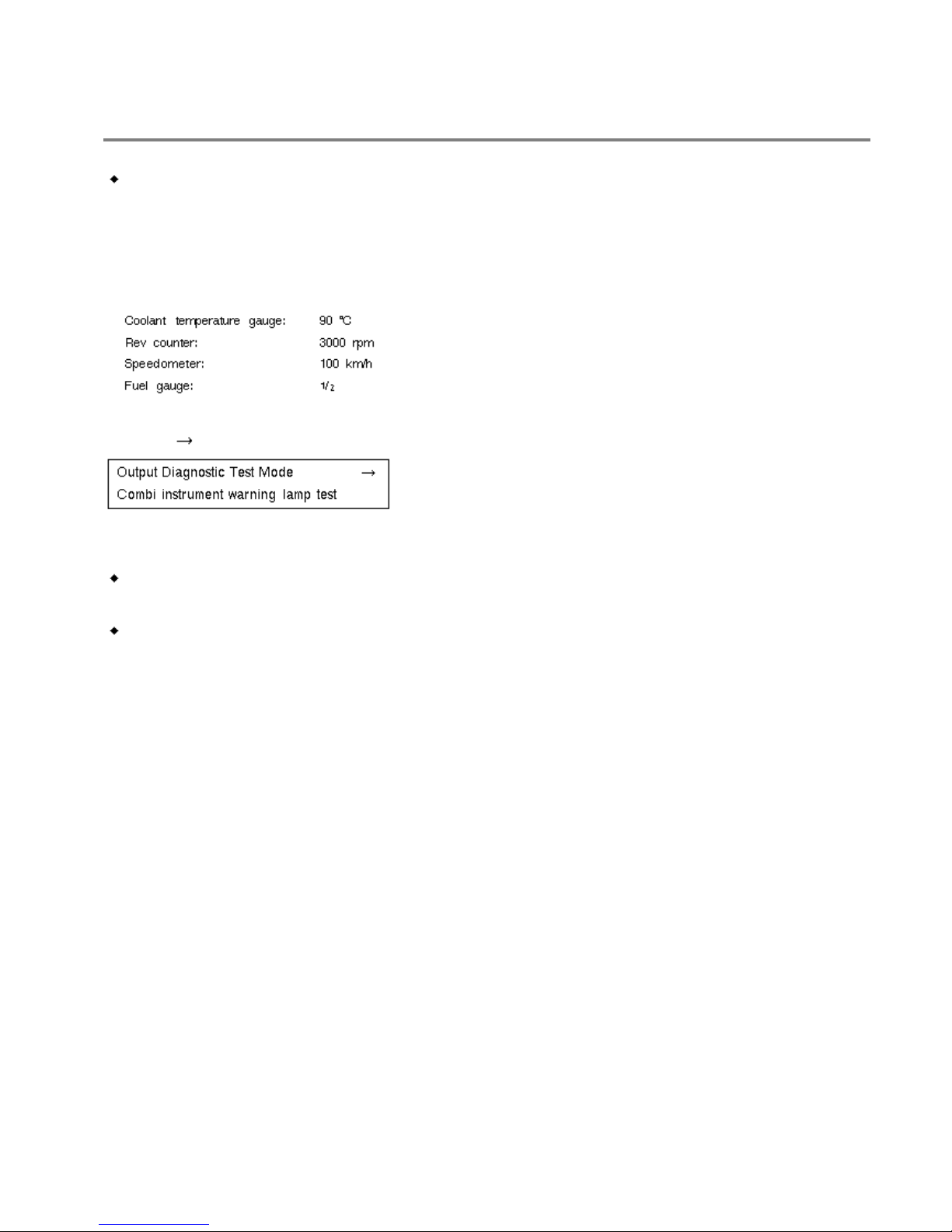
After checking movement over display ranges the following constants are displayed:
- Press key.
Indicated on display:
The warning lamps for
Brake system (insufficient brake fluid, ABS not working)
and additionally for Lowline and Midline instrument panels
Coolant temperature/coolant shortage indicator
Volkswagen Jetta, Golf, GTI 1999, 2000
Electrical Equipment On Board Diagnostic (OBD)
Instrument panel, On Board Diagnostic (OBD) (through MY 1999) (Page 01-27)
Brake pad wear (when activated using code)
Fuel reserve
Oil pressure
are activated and light up continuously.
On the Highline instrument panel the central display unit for warning lamps and navigation is
checked instead of the individual warning lamps.
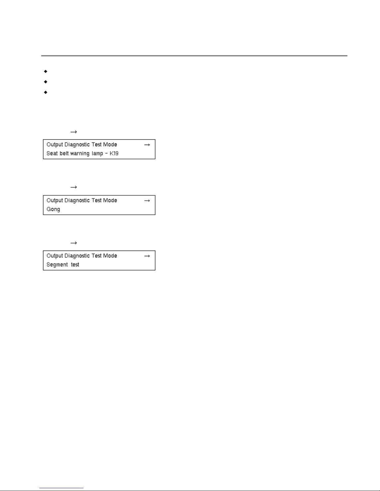
- Press key.
Indicated on display:
The seat belt warning lamp -K19- lights up (when activated by code).
- Press key.
Indicated on display:
The buzzer/gong is activated: a warning tone is emitted at intervals.
- Press key.
Indicated on display:
Midline and Lowline instrument panel:

Volkswagen Jetta, Golf, GTI 1999, 2000
Electrical Equipment On Board Diagnostic (OBD)
Instrument panel, On Board Diagnostic (OBD) (through MY 1999) (Page 01-28)
All LCD segments in speedometer display and in rev counter are activated and become visible.
In addition for Highline instrument panel:
All segments of display unit for Navigation and warning lamps are visible.
- Press key.
Indicated on display:
Instrument panel VDO:
Safety cut-off -air conditioner compressor cut-off- is activated approx. 5 seconds later (only
vehicles with air conditioning system)
No display in instrument panel!
Instrument panel MMO:
The coolant temperature warning lamp lights up and a warning sound is given.
Safety cut-off -air conditioner compressor cut-off- is activated approx. 5 seconds later (only
vehicles with air conditioning system)
- Press key.
Indicated on display:
- Press key.
Volkswagen Jetta, Golf, GTI 1999, 2000
Electrical Equipment On Board Diagnostic (OBD)
Instrument panel, On Board Diagnostic (OBD) (through MY 1999) (Page 01-29)
Indicated on display for instrument panels with manufacturer code MMO:
Indicated on display for instrument panels with manufacturer code VDO:
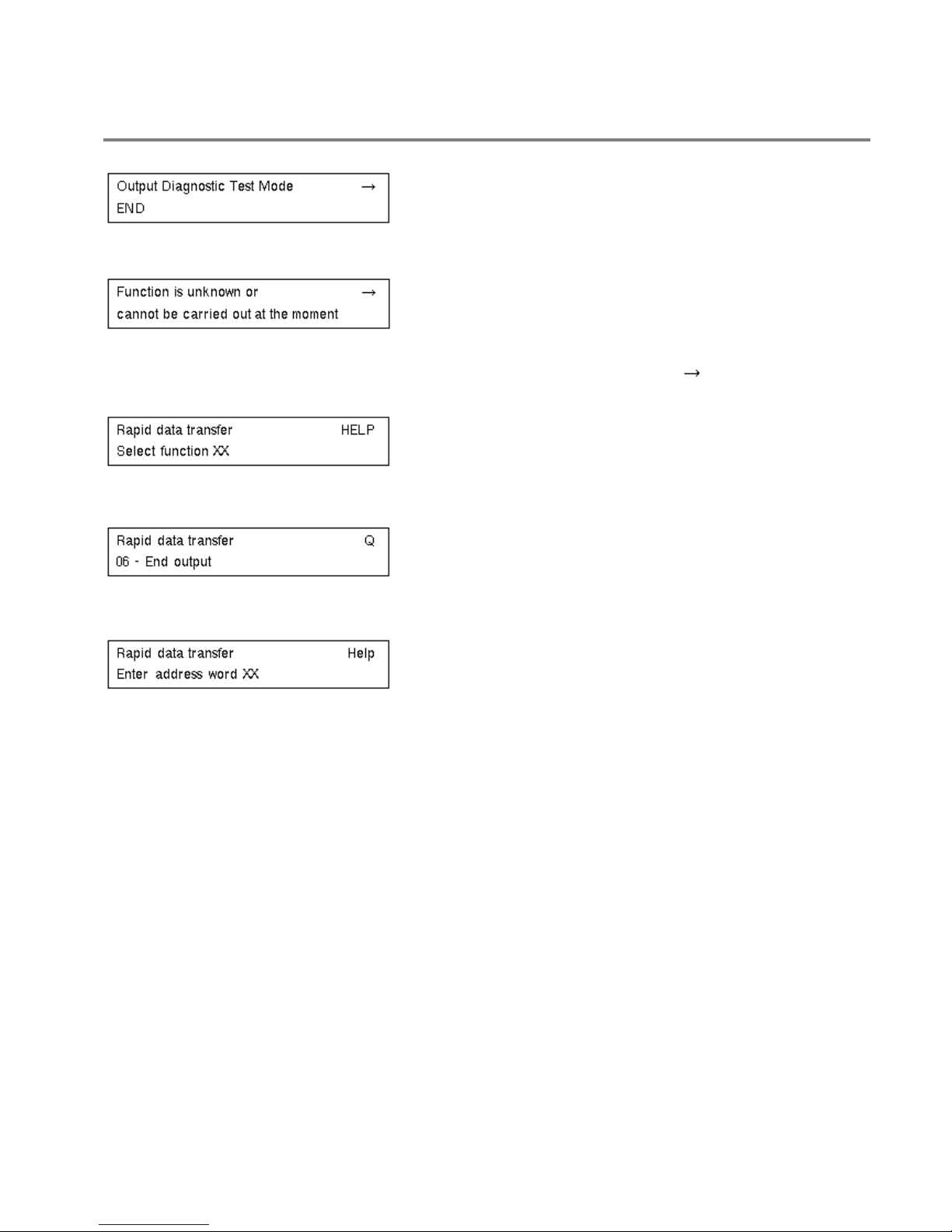
End Output Diagnostic Test Mode for VDO instrument panels by pressing key.
All actual values are displayed again.
Indicated on display:
- Press keys 0 and 6. (The function "End output" is selected with 06.)
Indicated on display:
- Confirm entry with key Q.
Indicated on display:
The tester is again in basic function.
 Loading...