


VFR-400 • 5403548 • REV D • 10/07
VFR-400
Installation, Operation, and
Instruction Manual
Releasing Panel for
Sprinkler Systems
All specifications subject to revision.
Manual #5403548 Rev D
10/07
1
VFR-400 • 5403548 • REV D • 10/07 |
|
Contents |
|
Operating Instructions Form................................................................................................................................................................ |
4 |
Design Guidelines................................................................................................................................................................................ |
5 |
General Description ............................................................................................................................................................................. |
5 |
System Features ................................................................................................................................................................................... |
5 |
Visual Indicators .................................................................................................................................................................................. |
6 |
Circuit Parameters................................................................................................................................................................................ |
7 |
Basic Operation.................................................................................................................................................................................... |
9 |
To Silence Signaling Appliance ......................................................................................................................................................... |
11 |
Remote Annunciator Operation ......................................................................................................................................................... |
12 |
Programming Mode Instructions ....................................................................................................................................................... |
14 |
Panel Visual Display .......................................................................................................................................................................... |
14 |
VFR-400 Standard Program Information .......................................................................................................................................... |
17 |
Wiring Diagram Programs ................................................................................................................................................................. |
20 |
VFR-400 Custom Program Information ............................................................................................................................................ |
45 |
Installation Instructions...................................................................................................................................................................... |
49 |
Wire Checkout ................................................................................................................................................................................... |
50 |
Battery Size Calculations................................................................................................................................................................... |
51 |
Battery Size Requirements/Maintenance........................................................................................................................................... |
51 |
2-Wire Smoke Detector Compatibility Data...................................................................................................................................... |
55 |
Releasing Device Compatibiilty ........................................................................................................................................................ |
56 |
Wire Routing for VFR-400 ................................................................................................................................................................ |
56 |
Connection Procedure for Battery And Voltage................................................................................................................................. |
58 |
Connection Drawing for Central And Remote Station ...................................................................................................................... |
58 |
2
VFR-400 • 5403548 • REV D • 10/07
Notes:
3

VFR-400 • 5403548 • REV D • 10/07
This is the safety alert system. It is used to alert you to potential personal injury hazards. Obey all safety messages that follow this symbol to avoid possible injury or death.
•The detection and suppression system employing this release panel must be designed by people trained and competent
in the design and layout of fire alarm and/or suppression systems for special hazard locations. The system shall be designed and installed in accordance with all local and national codes and ordinances as well as the approval of the Authority Having Jurisdiction. Only trained, qualified and competent individuals should install, program and/or service the VFR-400.
Competent people would be aware of these warnings, limitations, and requirements.
•High voltage electrocution hazard. Do not handle live AC wiring or work on the device while ac power is active.
This manual is designed to help with the specification, installation, and programming of the VFR-400 release panel. It is imperative that this manual be completely read and understood before the installation or programming of the panel. Save this manual for future reference.
•Zones programmed as MANUAL RELEASE will override any cross zoning features. If it is desired to not have a Manual Release override the cross zoning, program the zone as DETECTION and map accordingly.
*Locate the panel and all system components in the following nominal environment: *Indoor heated installation only, preferably an interior wall.
*Verify that the wire sizes are adequate for all initiating, notification, and release circuits. *Make certain the panel is properly grounded.
*Remove all electronic assemblies prior to any drilling, filing, reaming, or punching of the enclosure. When possible make all cable entries from the sides, bottom, or rear of the cabinet. Verify that they will not interfere with the batteries or other components. *The panel and system must be tested and maintained in accordance with all local and national codes and ordinances.
Operating Instructions Form
1)Fill in the name, address and telephone number of the servicing agency on the instruction sheet provided and frame and place adjacent to control panel at eye level.
2)The following documentation shall be delivered to the owner or their representative upon final acceptance of the system: An owners manual and installation instructions covering all system equipment.
Wiring diagrams
A detailed description of the programming and operating sequence of the system.
Fire Alarm System Limitations
Smoke detectors may not detect smoke when the smoke does not reach the detector. Such as smoke within walls, on the other side of walls, on other floors, behind closed doors, explosions, etc. Smoke detectors will not operate if they are not properly connected to the fire/release panel. The detectors and bases must be UL/ULC listed as being compatible with the panel. The detectors have a visible flashing light that indicates power is supplied to the detectors.
Notification appliances may not alert people if the people are not able to hear or see the appliances such as if they are in separate areas of the building or room.
A fire alarm/release panel will not operate without electrical power. The panel must have sufficient backup battery capability to power the panel for a specified amount of time in the event of an AC power failure. The batteries and release panel shall be tested and maintained in accordance with the testing and maintenance requirements of NFPA72.
In order for emergency forces, (Fire departments, etc.), to respond to events associated with this panel, the panel must transmit trouble, supervisory, and alarm signals to a monitoring facility either directly or through a main building fire panel.
A problem in an audible or visual device may not be apparent when the panel is in a normal condition.
4
VFR-400 • 5403548 • REV D • 10/07
Design Guidelines
People trained in the design of special hazard systems shall determine the selection and placement of the initiating devices and notification appliances connected to the VFR-400. This responsible party shall also be familiar with the premises being protected. The equipment shall be installed in accordance with the manufacturers instructions, the applicable version of NFPA 72 and all local codes and ordinances. For systems employing cross zoning of smoke detectors for the activation of the release circuit, this can include but is not limited to the installation of photoelectric and ionization types of detectors on separate zones. One of each type of detector on separate zones shall be installed in the coverage area selected for a single detector. The detectors would be installed in close proximity to each other.
The responsible party shall also determine the theory of operation regarding the programming sequence.
General Description
The model VFR-400 is a listed and approved, microprocessor based fire control/releasing panel. It is primarily designed for use as a releasing panel for pre-action, Surefire®, Firecycle® III, and deluge, water based extinguishing systems. They may also be used as stand alone fire control panels. These units comply with NFPA-13, NFPA-15,NFPA-72, and NFPA-750.
The VFR-400 complies with UL Standard 864, ULC S527-77, Canadian Electrical Code Part 1 C22.1, ULC S524, FM, CSFM and NYMEA.
System Features
•Four Class B (Style B) Initiating zones. Each initiating zone can be set up for any of the following:
·Alarm Zones
·Detection alarm zone
·Waterflow
·Linear Heat Detection up to 700 ohms per zone.
·Manual Release
·Viking Firecycle Detectors (Zone 1 only)
·Supervisory Zones
·Supervisory
·Tamper
·Low Air Supervisory
·High Air
·Low Air Alarm
Note: Only zones programmed as Detection, Waterflow, Linear Heat, Manual Release, Firecycle and Low Air Alarm can be mapped to outputs programed as release.
•Remote Annunciator Output for connection to RA-4410RC:
·RS-485 communication, (2-wire shielded cable required)
·Regulated 24VDC annunciator power
•Two Supervisory Zones, Class B (VDC Style B). These zones can be set up for any of the following:
·Supervisory
·Tamper
·Low Air Supervisory
·High Air
•Four Class B (Style Y) Output circuits. Each output can be set up for any of the following:
·Notification Appliance circuit
·Releasing circuit
·Supervisory Bell circuit
·Trouble Bell circuit
5

VFR-400 • 5403548 • REV D • 10/07
·Twelve Standard Programs for water based systems or custom program capability
·Releasing Zones can be set up for either normal or cross zoning operation
·All circuits inherently power limited per NEC 760 and UL 864 Section 14.4
·Initiating Circuit Disable feature
·Output Disable feature
·One-Man Walktest feature with automatic 30 minute restoration and releasing circuit disable
·Diagnostic Indicators
·Signal Silence button
·Manual Event scroll buttons
·Automatic resound of silenced trouble signals after 24 hours
·Built-in Trouble buzzer
·Common Relay Contacts for Alarm/Trouble/Supervisory/Waterflow
·32 Character Liquid Crystal Display (LCD)
·34 LED Display
·AC, Alarm, Supervisory, Trouble, Alarm silenced LED's (Pre-discharge/discharge LED)
·User Generated Banner Message
·User Generated Zone Labeling
·24 or 90 hour Battery Standby available (Where required by FM and Others)
·24 Hour Clock
·Password Protection
·Remote annunciator output
·Resettable 4-wire smoke detector power
Options
1)CAM - Module to convert one Class B Indicating Appliance Circuit to one Class A circuit.
2)CA2Z - Module to convert two Class B Initiating Device Circuits to two Class A circuits.
3)ARM-2 - Module to provide two Form C contacts activated by Indicating or Releasing, polarity reversing circuits
4)RA-4410-RC – Remote annunciator provides 34 LED’s for each zone in alarm supervisory or trouble, each output activated or in trouble, AC power, Power trouble, System trouble, Ground fault, Supervisory, Supervisory trouble, Alarm, Alarm silence and Pre-discharge/Discharge.
This equipment generates, uses, and can radiate radio frequency energy and if not installed and used in accordance with the instruction manual, may cause interference to radio communications. It has been tested and found to comply with the limits for a Class A computing device pursuant to Subpart J of Part 15 of FCC Rules which are designed to provide reasonable protection against such interference when operated in a commercial environment. Operation of this equipment in a residential area is likely to cause interference in which case the user at his own expense will be required to take whatever measures may be required to correct the interference.
Specifications
VFR-400 HOUSING
Type - 18 gauge sheet steel with hinged, removable, locked door Size - 18 1/2" x 14 5/8" x 4 3/4"
Finish - red cabinet with logo.
Knockouts - 4 - ½" and 2 - ¾" on top; 1 - ½" and 1 - ¾" each side; 2 - ½" and 1 - ¾" back VFR-400 Visual Indicators (Visible with door closed):
AC LED - Green Alarm Silenced - Amber
System Alarm LED - Red System Supervisory LEDAmber System Trouble LED - Amber
Pre-discharge/Discharge LED - Amber
32 Character Alpha-Numeric Liquid Crystal Display (LCD) Red alarm per zone
Amber trouble LED per zone
Common required systems status LED's
6
VFR-400 • 5403548 • REV D • 10/07
LCD
A 2 line 32 character alpha-numeric liquid crystal display shows the condition, status and circuit for all Alarm, Supervisory and Trouble conditions:
CONDITION |
STATUS |
CIRCUIT |
Alarm |
|
<user Defined Message> (Up To 10 Characters) |
Trouble |
Disabled |
Output #1 |
Supervisory |
Acknowledged |
Output #2 |
Tamper |
Silenced |
Output #3 |
Low Air |
|
Output #4 |
High Air |
|
Battery |
Aborted |
|
A.C. |
Pre-discharging |
|
Supervisory |
Releasing |
|
Zone #1 |
Released |
|
Zone #2 |
|
|
Zone #3 |
|
|
Zone #4 |
|
|
Ground |
VFR-400 Visual Indicators
|
In accordance with ULC S527-99 option B: |
|
|
LED Annunciator Module |
|
Red LED’s: |
Initiating Device Circuits Active (4), |
|
|
Notification/Release Circuits Active (4) |
|
|
Common Alarm (1) |
|
Green LED: |
AC Power |
|
Yellow LED’s: |
Initiating Device Circuits Troubles (4), |
|
|
Output Circuits Troubles (4) |
|
|
Supervisory Initiating Zone (4) |
|
|
Supervisory Bell Output Active (4) |
|
|
(1) each: Supervisory Zone, Supervisory 1, Supervisory 2, Power Trouble, Supervisory Trouble, System |
|
|
Trouble, Ground Fault, Discharging/Discharged, Alarm Silenced |
|
CONDITION |
STATUS |
LED State |
Trouble |
Non-Silenced |
Flashing |
Trouble |
Silenced |
Steady ON |
Alarm |
Non-Silenced |
Flashing |
Alarm |
Silenced |
Steady ON |
Supervisory |
Non-Silenced |
Flashing |
Supervisory |
Silenced |
Steady ON |
Pre-discharge |
|
Flashing |
Discharged |
|
Steady ON |
Control Buttons
•Signal Silence - Momentary, silences signaling circuits, (except those activated by zones programmed as WATERFLOW)
•System Reset - Momentary, resets all alarm circuits if condition has been corrected, removes power from initiating device circuits.
•Scroll Up - Scrolls LCD display to most recent events
•Scroll Down - Scrolls LCD display to previous events
NOTE: Buzzer silence is accomplished by scrolling through all events.
Circuit Parameters
All voltages regulated DC
Initiating Device Zones
For connection of dry contact initiating devices and compatible 2 wire smoke detectors. (All values nominal)
•4 Class B, Style B (Class A Style D module available)*
•Power limited, current limited to protect 2 wire smoke detectors
•Maximum 2 wire 24VDC smoke detector load per zone - 2.5 ma (Use only detectors that are listed in compatibility list.)
•Maximum Line resistance - 100 ohms (Except linear heat detection cable, 700 ohms per zone)
•End-of-Line Resistance - 5.1K
7
VFR-400 • 5403548 • REV D • 10/07
•Normal standby current - approximately 4.0 mA
•Standby voltage - 25VDC maximum, 13.4 minimum
•Maximum short circuit current - approximately 36mA
•Maximum Impedance for Alarm - 1400 ohms
•Normal supervisory current - approximately 4mA
•Low current trouble activation - approximately 3.3mA
•Alarm activation current - approximately 10mA
•Ripple voltage - .4 VDC
•Maximum operating voltage range: 22.5 - 25.9V DC
•Frequency - continuous
* In programs 6-9, Zone 1 is a normally closed zone for Firecycle® Detectors
Dedicated Supervisory Zones
•For dry contact supervisory devices such as tamper, low air, or high air switches
•2 Class B Style B circuit, latching
•Power limited, current limited
•End-of-Line resistance - 5.1K ohms
•Ripple Voltage - .1 VDC
•Frequency - continuous
•Maximum voltage - 25VDC
•Maximum short circuit current - approximately 36mA
•Maximum line resistance - 100 ohms
•Normal supervisory current - approximately 4mA
•Low current trouble activation - approximately 3.3mA
•Supervisory current condition - approximately 10mA
(Does not include power for any auxiliary devices)
Notification/Release Circuits
The output circuits of the VFR-400 are Non-coded. This allows the use of visual and audible appliances on the same circuit. If temporal notification appliances are required for evacuation, selectable tone appliances such as the AMSECO H24W horn or SH24W Series strobe/horns or a temporal module such as AMSECO TMP1-3A or equivalents should be used.
The notification outputs do not provide synchronization. If synchronization is required, use AMSECO SMD10-3A synchronization module or equivalent, as identified on page 55. The notification appliances shall be compatible with the sync module selected. The current requirements of the appliances, wire gauge, and length of wire run determine the maximum number of appliances that can be connected to one NAC and/or sync module. The maximum cannot exceed 1 amp or whatever the sync module selected can support, whichever is lower. The sync module shall be installed as per manufacturers instructions. Equivalent sync modules are shown on page 55.
•4 Class B Style Y (Class A Style Z module available for notification)
•Reverse polarity upon activation
•Power limited, Current limited
•24 VDC Regulated, rated 1 amp each, 2.5 amps total for all 4 circuits
•End-of-Line-Resistor - 5.1k ohms
•Frequency - continuous
•Maximum voltage - 27 VDC
•Ripple voltage - .3 VDC
•Maximum resistance for outputs programmed as RELEASING:
1divided by the current draw of the solenoid when activated
•Normal standy supervisory current - approximately .38mA
•Low current trouble activation - .11mA
•Maximum impedance - 5 Ohms
•High current trouble activation - .63ma
Low/Missing Battery
Causes battery and system trouble if battery falls below 22 volts. Battery circuit is fused and reverse polarity protection is provided.
Input Power
•Universal Input 120VAC, (60 Hz, 165VA) or 220VAC, (50 Hz, 185VA) 15 Amp Branch Line overcurrent protection required.
•System trouble is also generated if voltage drops below 102V.
Backup Power Requirements
• VFR-400 - Standby 121 mA, alarm 274 mA at 24VDC
8
VFR-400 • 5403548 • REV D • 10/07
Service Use
NFPA 13 - Automatic Sprinkler
NFPA 15 - Water Spray Fixed System
NFPA 16 - Foam Water Sprinkler and Foam Water Spray
NFPA 72 - National Fire Alarm Code
•Local
•Remote Station (protected premise unit)
•Central Station (protected premise unit)
NFPA 750 - Water Mist
Listings And Approvals
VFR-400 - UL Standard 864, ULC Standard S527, FM, CSFM and NYMEA
Terminals
•All terminals capable of handling #14 AWG wire
•All terminations have transient protection
•All four initiating device circuit terminals capable of handling linear heat detection.
Relay Outputs
•Common system alarm contacts SPDT rated 3 Amps, 30VDC resistive
•Common supervisory contacts SPST, N.O. rated 3 Amps, 30VDC resistive
•Common system trouble contacts SPDT rated 3 Amps, 30VDC resistive
•Common system waterflow contacts SPST, N.O. rated 3 Amps, 30VDC resistive
Auxiliary Power
•Auxiliary Power - 24VDC regulated. Rated 200 mA max. Current limited
•Resettable for 4-wire smoke detectors
Annunciator Connection
•Auxiliary Power - 24VDC regulated. Rated 200 mA max. Current limited for RA-4410-RC Annunciator, non-resettable power
•RS-485 For connection to RA-4410-RC remote annunciator
•Maximum 2000' with 22 AWG, 4000' with 20 AWG shielded cable
Optional Accessories
CA2Z module (Class A initiating device circuit)
Converts two Class B initiating device circuits to two Class A circuits.
CAM Module (Class A Indicating Appliance Circuit)
Converts indicating appliance circuit from Class B to Class A. One model CAM (Class A Module) is required for each circuit. (Do not use this on an output programmed as “TROUBLE BELL”.)
ARM-1/ARM-2 Module (Auxiliary Relay Module)
Activated by 24VDC Indicating and/or Releasing, polarity reversing circuits. The module provides a non-supervised DPDT Relay that can be used for fan shutdown, door release, elevator recall, etc.
RA-4410RC (Remote Annunciator)
Connects to RS-485 & 24VDC terminals. Provides 34 LED’s for each zone in alarm supervisory, or trouble, each output activated or in trouble, AC power, Power trouble, System trouble, Ground fault, Supervisory, Supervisory trouble, Alarm, Alarm silence and Pre-discharge/Discharge.
Basic Operation
In addition to the following events, the panel also provides an output via the RS-485 terminals to the RA-4410-RC remote annunciator to light the appropriate indicators. See remote annunciator operations, page 12. In addition, the remote annunciator has a silenceable buzzer that sounds on supervisory or trouble conditions.
Initiating Device Circuits Alarm Condition
An increase of current on any alarm initiating device circuit to approximately 10 mA or greater will result in the following:
Alarm (Except zones programmed as LOW AIR ALARM):
1)Activation of the common alarm relay contacts.
2)Activation of the output circuit(s) which are mapped to the initiating device circuit(s). Providing all zone(s) necessary for the activation of those circuits is in alarm
3)“ALARM” and zone # displayed on LCD.
4)Activation of the red ALARM LED in a flashing mode as well as corresponding zone. NOTE: The ALARM LED will continue to flash until the Signal Silence button is pushed. The silence button will remove power from all outputs set up as Indicating except those activated by zones programmed as Waterflow.
5)Activation of zones programmed as waterflow will operate the common waterflow relay contacts in addition to the above. Note: If Zone 1 is programmed as Firecycle, an open circuit will result in the above.
9
VFR-400 • 5403548 • REV D • 10/07
Do not silence signals until all occupants are evacuated to a safe area.
Low Air Alarm
1)Operation of supervisory relay contacts and local buzzer.
2)Activation of the notification appliance circuit(s) or releasing circuit(s) which are mapped to the initiating device circuit(s). Providing all zone(s) necessary for the activation of those circuits is in alarm
3)LOW AIR ALARM and <CIRCUIT #> displayed on LCD.
4)Activation of the amber supervisory LED in a flashing mode. NOTE: The supervisory LED will continue to flash until all events in the SUPERVISORY queue are viewed. This is accomplished by scrolling through all of the events by use of the scroll up and scroll down buttons. The LED will go steady after all alarm events have been viewed.
Supervisory
An increase of current to approximately 8 mA or greater on the supervisory initiating device circuit(s) or disabling an output programmed as releasing will result in the following:
1)Operation of supervisory relay contacts and local buzzer.
2)Operation of any output circuits that have been described as SUPERVISORY BELL.
3)“SUPERVISORY”, “TAMPER”, “LOW AIR”, or “HIGH AIR” and <CIRCUIT> displayed on LCD.
4)Activation of the amber SUPERVISORY LED in a flashing modes well as the corresponding zone LED. NOTE: The SUPERVISORY LED will continue to flash until all events in the SUPERVISORY queue are viewed. This is accomplished by scrolling through all of the events by use of the scroll up and scroll down buttons. The LED will go steady after all supervisory events have been viewed.
Trouble Conditions
Initiating Device Circuits
A decrease of current to approximately 3.3 mA or programming the zone as disabled on any initiating device circuit will result in the following:
1)Activation of trouble relay contacts and local buzzer.
2)Operation of any output circuits which have been described as TROUBLE BELL.
3)“TROUBLE” and <CIRCUIT> displayed on LCD.
4)Activation of the amber TROUBLE LED in a flashing mode as well as corresponding zone. NOTE: The TROUBLE LED will continue to flash until all events in the TROUBLE queue are viewed. This is accomplished by scrolling through all of the events by use of the scroll up and scroll down buttons. The LED will go steady after all trouble events have been viewed.
Note: When the circuits are operated in the Class A mode any trouble condition will require manual operation of the reset switch to restore the panel to normal after the fault has been removed.
A complete loss of power will result in the transfer of the common system trouble relay contacts. If Zone 1 is programmed as Firecycle, an increase in current to 10 mA or greater will result in the above.
Notification Appliance/Releasing Circuits
An increase of current to approximately 0.63 mA or a decrease in current to approximately 0.11 mA on any output circuit or connecting an indicating appliance backwards, or disabling an output will result in the following:
1)Activation of trouble relay contacts and local buzzer.
2)Operation of any output circuits which have been programmed as TROUBLE BELL. If this output is in trouble, a TROUBLE BELL on this output may not function correctly, depending on the type of trouble.
3)“TROUBLE” and “OUTPUT #” <CIRCUIT NO.> displayed on LCD.
Note: A current in excess of 2.5 Amps, when the panel is in the alarm condition, will result in an output trouble as described above.
A problem in an audible or visual device may not be apparent when the panel is in a normal condition. If the circuit indicates a trouble condition when the panel is in an alarm condition the problem must be located and corrected.
10
VFR-400 • 5403548 • REV D • 10/07
Ground Fault
A short between any circuit and earth ground will result in the following:
1)Activation of trouble relay contacts, trouble LED in a flashing mode, and local buzzer.
2)Operation of any output circuits which have been described as TROUBLE BELL.
3)“TROUBLE” and “GROUND” displayed on LCD.
Loss Or Reduction Of AC Power
A reduction in the AC input voltage will result in the following:
1)Activation of amber trouble LED in a flashing mode and local buzzer.
2)Operation of any output circuits which have been described as TROUBLE BELL.
3)“TROUBLE” and “A.C.” displayed on LCD.
4)LCD Backlight will be extinguished.
5)Loss of green AC LED.
6)The trouble relay contacts will transfer after 90 minutes.
Low Battery Voltage
Loss of or reduction of battery voltage to 22 volts will result in the following:
1)Activation of common trouble relay contacts, amber trouble LED in a flashing mode and local buzzer.
2)Operation of any output circuits that have been described as TROUBLE BELL.
3)“TROUBLE” and “BATTERY” displayed on LCD.
Loss Of Auxiliary Power Output
Loss of output of the auxiliary power will result in the following:
1)Activation of trouble relay contacts, trouble LED in a flashing mode and local buzzer.
2)Operation of any output circuits that have been described as TROUBLE BELL.
3)“TROUBLE” and “AUX LOW” displayed on LCD.
4)Activation of amber POWER TROUBLE LED.
5)Activation of amber SYSTEM TROUBLE LED.
To Silence The Buzzer Or Outputs That Have Been Described As Trouble Or Supervisory Bell
Press the scroll up or scroll down buttons. Once all events in the trouble or supervisory queue have been viewed, the buzzer and appropriate output will silence. The applicable system TROUBLE or SUPERVISORY LED will change from flashing to steady. Note: Any continuous trouble conditions that have been silenced automatically resound 24 hours after the first trouble condition was silenced.
11
VFR-400 • 5403548 • REV D • 10/07
To Silence A Signaling Appliance
Press the SIGNAL SILENCE button. All silencable outputs will de-activate. A trouble condition will be created and the amber Alarm Silenced LED will light.
Where audible and/or visual indicators are being used as an evacuation signal, do not silence an alarm condition without investigating and determining that an emergency condition does not exist.
Notes: 1) Alarms initiated from zones that are in the waterflow mode cannot be silenced. The panel must be reset to silence audible alarm devices.
2)If silenceable waterflow indication is desired it must be programmed as conventional alarm and annunciated on the zone identification portion of the LCD.
To Reset an Alarm or Supervisory Condition
1)Determine the cause of the alarm condition and if necessary remove the cause.
2)Press the reset button.
To Reset A Trouble Condition
1)Determine the cause of the trouble condition and remove the cause.
2)This circuit is self-restoring. When all trouble conditions are removed all indications will return to normal.
Note: When an initiating device zone is operated in a Class A (Style D) mode any trouble condition will require manual operation of the reset switch to restore the panel to normal after the fault has been corrected.
Lamp Test
When the panel is in a Normal Condition, pushing the top two buttons will illuminate all of the LED's and display for approximately one second.
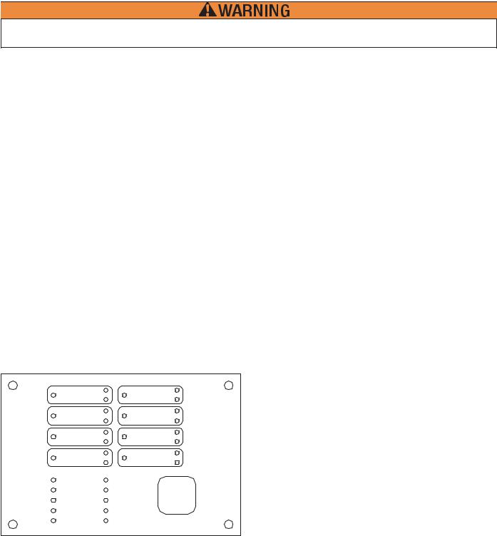
Remote Annunciator Model RA-4410RC Operation
Red LED’s: |
Initiating Device Circuits Active (4) |
|
Notification/Release Circuits Active (4) |
|
Common Alarm (1) |
Green LED’s: |
AC Power |
Yellow LED’s: |
Initiating Device Circuits troubles (4) |
|
Output Circuit Troubles (4) |
|
supervisory Bell Output Active (4) |
(1) each: Supervisory Zone, Power Trouble, Supervisory Trouble, System Trouble, Ground Fault, Discharging/Discharged, Alarm Silenced RA-4410RC
ZONE 1 |
OUTPUT 1 |
ZONE 2 |
OUTPUT 2 |
ZONE 3 |
OUTPUT 3 |
ZONE 4 |
OUTPUT 4 |
AC POWER |
SUPERVISORY 1 |
POWER TBL |
SUPERVISORY 2 |
SYSTEM TBL |
LAMP TEST |
COMMON ALARM |
|
SUP TBL |
ALARM SILENCE |
GROUND FAULT |
STEADY: DISCHARGE |
|
FLASHING: PRE-DISCHARGE |
DWG# 3550-17VKG
Basic Operation
The appropriate LED flashes to indicate a change of status on the panel. A trouble or supervisory condition will flash the appropriate Yellow LED indicating the location of the condition. If any outputs are programmed as TROUBLE or
SUPERVISORY BELL, that Yellow output LED will flash indicating the output is activated. Pressing the BUZZER SILENCE button on the panel changes the flashing zone Amber LED to steady on and turns the flashing Yellow output LED off.
An alarm or low air alarm condition will flash a Red LED indicating the zone in alarm and any outputs mapped to that zone that
12
VFR-400 • 5403548 • REV D • 10/07
have activated. Pressing the SIGNAL SILENCE button changes the flashing Red Zone LED to steady on and the flashing Red Output LED mapped to that zone off unless the output is programmed as RELEASE. In addition, the Yellow ALARM/ SILENCE LED will light.
Any zone programmed as WATERFLOW is considered non-silenceable so the signal and buzzer silence buttons will have no effect on the flashing zone and output LED's. A buzzer on the annunciator sounds for any trouble condition. When the panel has a trouble or supervisory condition, pressing the SILENCE/LAMP TEST button silences the condition at the panel and all annunciators. When the panel is in a normal state, pressing the SILENCE/LAMP TEST button can be used to test the LED's.
The release panel supervises and communicates with the annunciator via separate connections for the RS-485 communication and 24VDC power requirements of the RA-4410-RC. Separate cables should be used for power and communication. Shielded cable shall be used for the communication line. Up to three annunciators can be connected to one panel. A rotary switch is provided on the panel to indicate how many annunciators are connected. Another rotary switch is on the annunciator to set the address. The annunciators must be addressed consecutively. See page 54 for wiring information. Refer to bulletin #8840024 for installation
instructions and maximum wire run.
Test Procedure
The system should be inspected, tested, and maintained in accordance with NFPA-72 National Fire Alarm Code, Chapter 10 and
any other requirements of the local authority having jurisdiction.
Test Procedure (Canada)
The system should be inspected, tested, and maintained in accordance with ULC Standard CAN/ULC-S536 and any other requirements of the local authority having jurisdiction.
Testing should be done as a minimum as described below:
1)Notify the fire department or other receiving station if alarm, supervisory and/or trouble signals are transmitted.
2)Notify the proper building personnel so that audible and/or visual signals can be ignored.
3)If the release panel is monitored by a building fire alarm panel, take appropriate action to eliminate any unwanted events.
4)Momentarily open each of the following circuits.
a)Each initiating device zone
b)Supervisory circuit
c)Indicating Appliance/Releasing circuit - observe that this results in a trouble condition and all indicators operate as described in the appropriate preceding section for the particular circuit that is faulted.
5)Move the PROGRAM switch down. The LCD should respond: “LOOK AT HISTORY?”. Press the FUNCTION button until the display reads PASSWORD=000. Enter password if changed from factoy or press the SET button three times. Press the FUNCTION (bottom) button until the LCD reads “SYSTEM MODE: NORMAL”. Press the SELECT button. The LCD will read “SYSTEM MODE:
ONE MAN WALKTEST”. Press the SET button then move the PROGRAM switch up. The panel will respond with “ONE MAN WALKTEST” and the time. The trouble LED will light. Any output described as “RELEASING” will automatically be disabled.
Failure to enter the walktest mode and subsequent operation of initiating zones may result in a release.
After 30 minutes of no activity in the walk test mode the panel automatically reverts to normal operation.
6)Operate each initiating device on all zones. All audible and visual alarm devices should operate for about 3 seconds. Then the system will automatically reset allowing the user to go to the next initiating device.
7)Operate each initiating device on the supervisory circuit. Observe that all the indications described in the section on supervisory conditions occur.
8)Move the PROGRAM switch down again. The LCD should respond: “LOOK AT HISTORY?”
Press the FUNCTION button until the display reads PASSWORD=000. Enter password if changed from factory or press the SET button three times.
Press the FUNCTION (bottom) button until the LCD reads: “SYSTEM MODE: ONE MAN WALKTEST” Press the SELECT (middle) button. The LCD will read: “SYSTEM MODE: NORMAL”
Press the SET (top) button then restore the PROGRAM switch to the up position. The LCD will show the normal banner message.
9)All audible and visual indicators should be off.
10)Notify all building, fire department, and/or other receiving station personnel that the test has concluded.
Maintenance: Test batteries per local and national standards. At a minimum replace batteries every four (4) years or sooner depending on test results. The date of purchase shall be marked on all batteries.
13
VFR-400 • 5403548 • REV D • 10/07
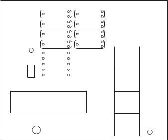
Programming Mode Instructions
To use the Programming Mode push the program switch down (see drawing below).
Panel Visual Display
As a general rule, the following applies on the Programming Mode buttons: The top button (SET) sets the message on the display into the memory.
The middle button (SELECT) scrolls through the selections available for the function displayed. The bottom button (FUNCTION) allows the user to skip the function without changing the program.
ZONE 1 |
OUTPUT 2 |
ZONE 2 |
OUTPUT 1 |
ZONE 3 |
OUTPUT 3 |
ZONE 4 |
OUTPUT 4 |
AC POWER |
SUPERVISORY1 |
POWER TBL |
SUPERVISORY2 |
SYSTEM TBL |
COMMONALARM |
RUN |
ALARM SILENCE |
SUPTBL |
|
PROGRAM |
STEADY: DISCHARGE |
GROUND |
|
FAULT |
FLASHING: |
|
PRE-DISCHARGE |
PROGRAM MODE
SET
SELECT
FUNCTION
VIEWING ANGLE
RUN
MODE
SCROLL-UP
BUZZER SILENCE
} TESTLAMP
SCROLL-DOWN BUZZER SILENCE
SIGNALSILENCE
SYSTEM RESET
DWG# 3550-18VKG
To program, push the Program Switch down.
There is no capability to back up screens in the program mode. If a mistake was made during programming, move the program switch back up, then move it down and start from the beginning.
To exit the program mode at any time, move the Program Switch up.
When the programming switch is down (see Panel Visual Display) the following will appear in the display window:
L |
O |
O |
K |
|
A |
T |
|
|
|
|
|
|
|
|
|
H |
I |
S |
T |
O |
R |
Y |
? |
|
|
|
|
|
|
|
|
History
To examine the HISTORY press the top button, the display window will show the time and date of the last event or action. To skip to the next function or to exit history, press the FUNCTION (bottom) button.
SET |
|
Press the SET button to discover the time and date of the last event or action and to scroll forward. |
SELECT |
|
To scroll back, press the SELECT button. |
|
||
|
||
FUNCTION |
|
To exit or skip HISTORY, press the bottom button. |
|
||
|
||
|
|
|
14

|
|
|
|
|
|
|
|
|
|
|
|
|
VFR-400 • 5403548 • REV D • 10/07 |
||||
|
|
|
|
|
|
|
|
|
|
|
|
|
|
|
|
|
|
S |
E |
T |
|
T |
I |
M |
E |
? |
|
|
|
|
|
|
|
|
|
|
|
|
|
|
|
|
|
|
|
|
|
|
|
|
|
|
|
Date/Time |
|
|
|
|
|
|
|
|
|
|
|
|
|
|
|||
SELECT |
|
|
|
To change the time, press the SELECT button. |
|||||||||||||
|
|
|
|||||||||||||||
FUNCTION |
|
|
|
To exit to the next function, press the bottom button. |
|||||||||||||
|
|
|
|||||||||||||||
|
|
|
|||||||||||||||
|
|
|
|
|
|
|
|
|
|
|
|
|
|
|
|
|
|
If the middle button is pushed, the date and time will appear in the display window:
0 1 / 0 5 / 2 0 0 7
The date is shown at the top and the time at the bottom of the display window. “MINUTES” indicates that the user can now change the minutes.
SET |
|
Pressing the SET button will decrease the minutes |
SELECT |
|
Pressing the SELECT button will increase the minutes. |
|
||
|
||
FUNCTION |
|
When finshed setting the minutes, Press the bottom button. The minutes will change to hours. |
|
||
|
||
|
|
|
Continue this process and change the DAY, MONTH and YEAR. When you have finished changing the year, press the FUNCTION (bottom) button. A display similar to the following will appear:
P A S S W O R D = 0 0 0
^
Password
This display prevents unauthorized programming of the panel by requiring the user to enter the proper password. To select the appropriate number for the space indicated by the ^ symbol, press the SELECT button. When the proper number is displayed press the SET button to set the number and move to the next space. If the wrong password is entered, the panel will display "Push Programming Switch Up". All panels are shipped from the factory with a password of 000. If the password is lost contact Potter.
SET |
|
After selecting the desired number, press the SET button to set and move to the next number. |
SELECT |
|
Press the SELECT button to scroll through the numbers. |
|
||
|
||
FUNCTION |
|
Pressing the bottom button will have no effect. |
|
||
|
||
|
|
|
15

VFR-400 • 5403548 • REV D • 10/07
After entering the correct password, a display similar to the following will appear:
I |
N |
I |
T |
|
Z |
O |
N |
E |
|
# |
1 |
|
|
|
|
E |
N |
A |
B |
L |
E |
D |
|
|
|
|
|
|
|
|
|
Zone Disabled/Enabled
This display allows the user to ENABLE or DISABLE Initiating zones. This display window shows that initiating ZONE #1 is enabled. To toggle from ENABLED to DISABLED or visa versa, press the SELECT button.
SET |
|
After selecting ENABLED or DISABLED, press the SET button to set and move to the |
|
|
next zone. |
SELECT |
|
Press the SELECT button to toggle between ENABLED or DISABLED. |
|
||
|
|
|
FUNCTION |
|
To skip to the next function, press the bottom button. |
|
|
|
After selecting all four zones or pressing the FUNCTION (bottom) button, the following will appear in the display window:
O |
U |
T |
P |
U |
T |
|
# |
1 |
|
|
|
|
|
|
|
E |
N |
A |
B |
L |
E |
D |
|
|
|
|
|
|
|
|
|
Output Enable/Disable
This display allows the user to ENABLE or DISABLE any of the output circuits.
SET |
|
After selecting ENABLED or DISABLED, press the SET button to set and move to the next output. |
|
|
|
SELECT |
|
Press the SELECT button to toggle between ENABLED or DISABLED. |
|
||
FUNCTION |
|
To skip to the next function, press the bottom button. |
|
||
|
||
|
|
|
After selecting all four outputs or pressing the FUNCTION (bottom) button, the following will appear in the display window:
Disabling any input or outputs will create a trouble condition on the panel.
Disabling a releasing circuit will create a supervisory condition.
S |
Y |
S |
T |
E |
M |
|
M |
O |
D |
E |
: |
|
|
|
|
N |
O |
R |
M |
A |
L |
|
|
|
|
|
|
|
|
|
|
16
VFR-400 • 5403548 • REV D • 10/07
One Man Walktest
This display allows the user to select system mode NORMAL or ONE MAN WALKTEST by pressing the SELECT button to toggle back and forth from NORMAL to ONE MAN WALKTEST. When the desired mode is displayed, press the SET button. If ONE MAN WALKTEST is selected for test purposes, the display must be restored to the NORMAL setting after the test is completed by toggling to it using the SELECT button.
After 30 minutes of no activity the panel automatically reverts to normal.
SET |
|
After selecting NORMAL or ONE MAN WALKTEST, press the SET button to set that mode. |
SELECT |
|
Press the SELECT button to toggle between NORMAL and CROSS ZONED. |
|
||
|
||
FUNCTION |
|
Press the bottom button to skip to the next function. |
|
||
|
||
|
|
|
After selecting the operating mode or pressing the FUNCTION button a display similar to the following will appear in the display window:
P R O G R A M # 1
VFR-400 Standard Program Information
The VFR-400 has 12 standard programs which are detailed in the following pages. Selecting one of these programs will automatically program every function of the panel except the custom banner and zone message functions.
Notes:
The release discharge time is continuous for all programs not employing the Firecycle feature. The default soak timer for the Firecycle feature is continuous.
The following is an explanation of how the various programs operate and information about the types of
devices that are to be connected to the input and output zones. If none of the standard programs are acceptable for the installation required, select the custom program #0 then press the SET button. This will allow the user to custom program the panel. Turn to
page 45 for custom program information. |
|
|
|
Type |
Description |
Alarm Zones |
Detection |
Smoke Detectors, Spot Type Heat Detectors |
|
Waterflow |
PS10 Pressure Switch |
|
Linear Heat |
Cable Type Heat Detectors |
|
Manual Release |
Pull Stations |
|
Firecycle |
Viking normally closed heat detectors |
Supervisory Zones |
Supervisory |
Valve Tamper, Low Air, High Air, Room Temperature |
|
Low Air supervisory |
Low Air Switch |
|
High Air |
High Air Switch |
|
Tamper |
Valve Tamper Switch |
|
Low Air Alarm * |
PS10, PS40 |
* Not available on Supervisory Zones Sup 1 or Sup 2
17

|
|
VFR-400 • 5403548 • REV D • 10/07 |
Outputs |
Alarm |
24VDC Bells, Horns, Strobes, to indicate an alarm condition. |
|
Release |
Solenoid Valve, Squib, Releasing Mechanism |
|
Supervisory |
24VDC Bells, Horns, Strobes, to indicate a supervisory condition. |
|
Trouble |
24VDC Bells, Horns, Strobes, to indicate a trouble condition. |
To program the VFR-400 to operate with one of the following 12 standard programs:
1)Press SELECT button to scroll to the program number (#1 thru #12) you desire.
2)Press SET button.
3)Turn to page 48 to program the banner message and to finish programming the panel.
SET |
|
After selecting the proper program number, press the SET button to set the program and move to the next function. |
SELECT |
|
Press the SELECT button to scroll through the programs. |
|
||
|
||
FUNCTION |
|
Press the bottom button to skip to the next function. |
|
||
|
||
|
|
|
After selecting the desired program number with the middle button, SET must be pressed to set the program. When the Firecycle programs (6-9) are selected, only outputs #3 and #4 can be selected as releasing.
If the Firecycle feature is used, Firecycle heat detectors must be connected to Zone 1. Zone 1 follows the status of the Firecycle detector. When the detector resets, a soak timer is initiated. The default soak timer is continuous. The soak timer is user selectable to 30, 60, or 90 seconds or 2 - 20 minutes in 1 minute increments.
18
 Loading...