


Viking Installation Guide
IMPORTANT–Please Read and Follow!
•Before beginning, please read these instructions completely and carefully.
•Be sure to DISCONNECT THE PLUG of the microwave oven from the electrical outlet before installing the built-in trim kit. Remove the turntable from the oven cavity.
•Because the kit includes metal parts, caution should be used in handling and installation to avoid the possibility of injury.
•Do not remove permanently affixed labels, warnings, or plates from the product. This may void the warranty.
•Please observe all local and national codes and ordinances.
•The installer should leave these instructions with the consumer who should retain for local inspector’s use and for future reference.
•This built-in trim kit is designed for use only with Viking convection and Conventional microwave ovens specifying built-in trim kit VMTK272, VMTK302, VMTK362, VMTK277, VMTK307 or VMTK367 on the rating label on the bottom face plate of the oven cavity.
•Your oven can be built into a cabinet or wall by itself or above any electric wall oven or warming drawer.
Parts Included in VMTK kits
Front Frame Assembly QTY 1 |
27" & 30"Surface Mount |
|
|
Template 2-sided |
|
Back Frame |
or 36"Surface Mount |
|
Template single-sided |
||
QTY 1 |
||
QTY 1 |
||
|
USE THIS SIDE OF TEMPLATE FOR MODELS
VMTK272 and VMTK302 ONLY.
BUILT-IN TRIM KIT TEMPLATE
FOR CUSTOM SERIES MICROWAVE OVEN
Front Frame
QTY 1
Bottom Duct Assembly QTY 1
*
Duct (A)-1 QTY 1 * |
Duct (A)-3 QTY 1 * |
Duct (A)-2 QTY 1 * |
Screw A (1/2" length) |
|
QTY 10 * |
Duct (B) QTY 1 * |
Screw B (1-3/4" length) |
|
QTY 4 |
||
|
Cushion QTY 3 |
Duct (C) QTY 1 * |
Screw C (3/4" length) |
|
|
QTY 2 |
*VMTK277, VMTK307 and VMTK367 ONLY.
Custom Series Convection /
Conventional Microwave Built-In Trim Kit
111 Front Street
Greenwood, Mississippi 38930 USA

Basic Specifications
|
|
|
|
|
|
|
|
|
|
|
|
|
|
|
Microwave Oven |
|
Built-In Custom Trim Kits |
|
|
||||||
|
Description |
CONVECTION |
VMOC206 |
VMTK277 |
VMTK307 |
VMTK367 |
|
|||||
|
Overall Width |
24-5/8" |
(62.5 cm) |
|
26-1/2" |
(67.3 cm) |
29-1/2" |
(74.9 cm) |
35-1/4" |
(89.5 cm) |
|
|
|
Overall Height |
14-7/8" |
(37.7 cm) |
|
19-13/16" |
(50.1 cm) |
19-13/16" |
(50.1 cm) |
19-13/16" |
(50.1 cm) |
|
|
|
from Bottom |
|
|
|||||||||
|
|
|
|
|
|
|
|
|
|
|
|
|
|
Overall Depth |
19" |
(48.3 cm) |
|
|
|
|
N/A |
|
|
|
|
|
from Rear |
|
|
|
|
|
|
|
||||
|
|
|
|
|
|
|
|
|
|
|
|
|
|
|
Width |
16-1/8" |
(40.9 cm) |
|
|
|
|
|
|
|
|
|
Oven Interior |
Height |
9-5/8" |
(24.4 cm) |
|
|
|
N/A |
|
|
|
|
|
Depth |
16-1/8" |
(40.9 cm) |
|
|
|
|
|
|
|||
|
|
|
|
|
|
|
|
|
||||
|
|
Overall |
1.5 cu. ft. |
|
|
|
|
|
|
|
|
|
|
Cutout Width |
|
N/A |
|
Min. |
25" |
(63.5 cm) |
|
||||
|
Cutout Height |
|
N/A |
|
Min. |
18-11/16" |
(46.9 cm) |
|
||||
|
Cutout Depth |
|
N/A |
|
Min. |
20-1/8" |
(51.1 cm) |
|
||||
|
Electrical |
120VAC/60 Hz (UL) |
|
|
|
|
|
N/A |
|
|
|
|
|
Requirements |
117VAC/60 Hz (CSA) |
|
|
|
|
|
|
|
|||
|
|
|
|
|
|
|
|
|
||||
|
Maximum Amp |
1.55 KW |
13 amps (UL) |
|
|
|
|
N/A |
|
|
|
|
|
Usage |
1.5 KW |
13 (CSA) |
|
|
|
|
|
|
|
||
|
|
|
|
|
|
|
|
|
||||
|
Approximate |
60 lbs. |
(27.2 kg) |
|
19 lbs. |
(8.6 kg) |
20 lbs. |
(9.1 kg) |
23 lbs. |
10.5 kg |
|
|
|
Shipping Wt. |
|
|
|||||||||
|
|
|
|
|
|
|
|
|
|
|
|
|
|
Description |
CONVENTIONAL |
VMOS201 |
VMTK272 |
VMTK302 |
VMTK362 |
|
|||||
|
Overall Width |
24" |
(60.9 cm) |
|
26-1/2" |
(67.3 cm) |
29-1/2" |
(74.9 cm) |
35-1/4" |
(89.5 cm) |
|
|
|
Overall Height |
13-3/8" |
(33.9 cm) |
|
18-1/4" |
(46.3 cm) |
18-1/4" |
(46.3 cm) |
18-1/4" |
(46.3 cm) |
|
|
|
from Bottom |
|
|
|||||||||
|
|
|
|
|
|
|
|
|
|
|
|
|
|
Overall Depth |
19-1/4" |
(48.9 cm) |
|
|
|
|
N/A |
|
|
|
|
|
from Rear |
|
|
|
|
|
|
|
||||
|
|
|
|
|
|
|
|
|
|
|
|
|
|
|
Width |
17-3/8" |
(44.1 cm) |
|
|
|
|
|
|
|
|
|
Oven Interior |
Height |
10-1/2" |
(26.6 cm) |
|
|
|
N/A |
|
|
|
|
|
Depth |
18-5/8" |
(47.3 cm) |
|
|
|
|
|
|
|||
|
|
|
|
|
|
|
|
|
||||
|
|
Overall |
2.0 cu. ft. |
|
|
|
|
|
|
|
|
|
|
Cutout Width |
|
N/A |
|
Min. |
|
24-3/8" |
(61.9 cm) |
|
|||
|
|
|
Max. |
|
24-11/16" |
(62.7 cm) |
|
|||||
|
|
|
|
|
|
|
|
|||||
|
Cutout Height |
|
N/A |
|
Min. |
|
16-3/4" |
(42.5 cm) |
|
|||
|
|
|
Max. |
|
17" |
(43.2 cm) |
|
|||||
|
|
|
|
|
|
|
|
|||||
|
Cutout Depth |
|
N/A |
|
Min. |
|
20" |
(50.3 cm) |
|
|||
|
Electrical |
120VAC/60 Hz |
|
|
|
|
|
|
N/A |
|
|
|
|
Requirements |
|
|
|
|
|
|
|
|
|
||
|
|
|
|
|
|
|
|
|
|
|
|
|
|
Maximum Amp |
1.5 KW |
13 amps |
|
|
|
|
N/A |
|
|
|
|
|
Usage |
|
|
|
|
|
|
|
||||
|
|
|
|
|
|
|
|
|
|
|
|
|
|
Approximate |
46 lbs. |
(20.9 kg) |
|
14 lbs. |
(6.5 kg) |
15 lbs. |
(6.9 kg) |
18 lbs. |
(8.2 kg) |
|
|
|
Shipping Wt. |
|
|
|||||||||
|
|
|
|
|
|
|
|
|
|
|
|
|
|
|
|
|
|
|
|
|
|
|
|
|
|
E2
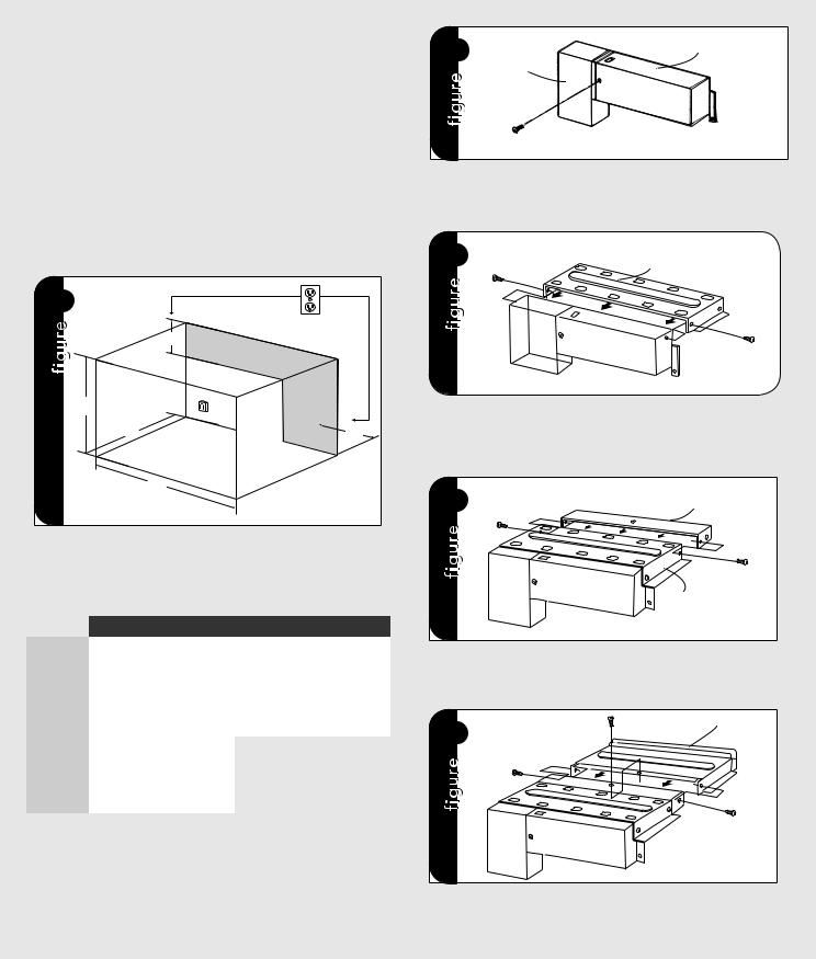
Cabinet or Wall Cutout
Provide an opening in the wall or cabinet as indicated in figure 1. The depth should be a minimum of 20-1/8" (51.1 cm). If the Depth (C) dimension is greater than 21" (53.3 cm), the outlet location may be in any area on the rear wall. The floor of the opening should be constructed of plywood strong enough to support the weight of the oven (about 100 lbs.) and should be level for proper operation of the oven.
Note: While the proper functioning of the oven does not require that the opening be enclosed (with sides, ceiling and rear partition), this may be required by local code, and it is suggested that the local code be checked for any such requirement.
1
E
A
C  D
D
B
Surface Mount Cutout Dimensions
* For flush mount dimensions please see installation template and flush mount installation on page 5-6.
|
|
CONVECTION |
CONVENTIONAL |
|||
|
|
|
|
|
|
|
(A) Height |
|
18-1/2" |
(46.9 cm) |
Min. |
16-3/4" |
(42.5 cm) |
|
|
|
Max. |
17" |
(43.2 cm) |
|
|
|
|
|
|||
|
|
|
|
|
|
|
(B) Width |
|
25" |
(63.5 cm) |
Min. |
24-3/8" |
(61.9 cm) |
|
|
|
Max. |
24-11/16" |
(62.7 cm) |
|
|
|
|
|
|||
|
|
|
|
|
|
|
(C) Depth |
Min. |
20-1/8" |
(51.1 cm) |
Min. |
20-1/8" |
(51.1 cm) |
|
|
|
|
|
|
|
(D) |
Min. |
6" |
(15.2 cm) |
|
|
|
Max. |
11-1/2" |
(29.2 cm) |
|
|
|
|
|
|
|
|
|||
|
|
|
|
|
|
|
(E) |
Min. |
4" |
(10.2 cm) |
|
|
|
Max. |
5" |
(12.7 cm) |
|
|
|
|
|
|
|
|
|||
|
|
|
|
|
|
|
ELECTRICAL OUTLET LOCATION: Outlet should NOT be in the shaded area as indicated on figure 1. At the rear of the opening, provide a 3-pronged, polarized, electrical outlet, 115-120 volt AC, 15 amp or larger.
Exhaust Duct Assembly
2 |
DUCT (C) |
DUCT (B) |
SCREW (A)
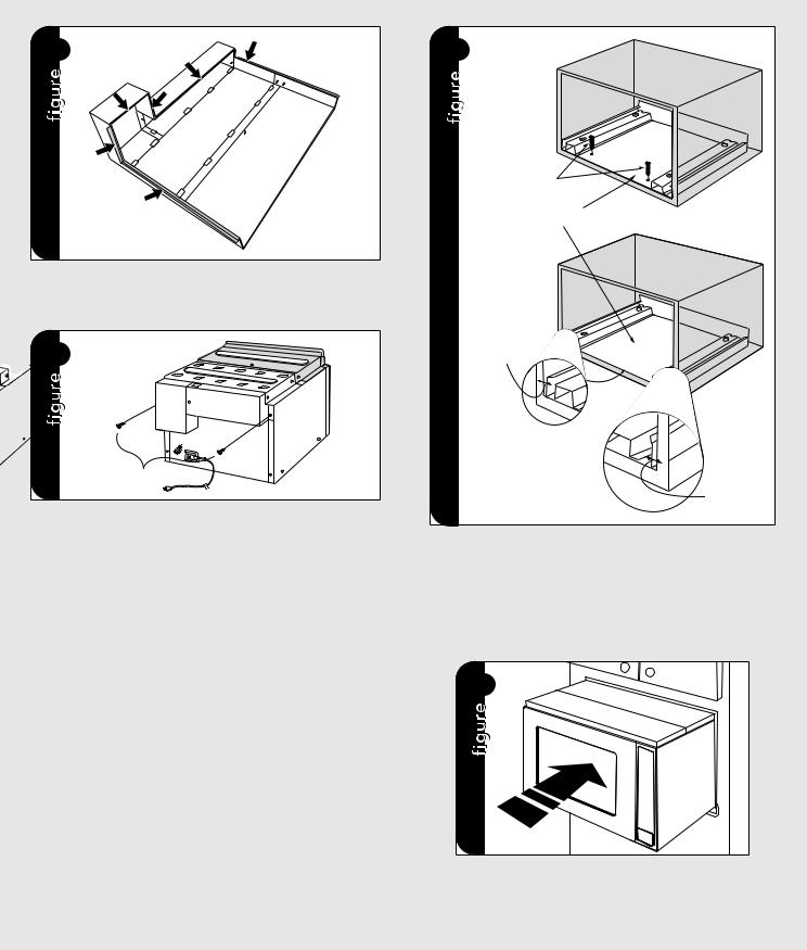
EXHAUST DUCT ASSEMBLY: Insert the edge of DUCT (B) into the hold lip of DUCT (C). Secure together by using a SCREW (A) provided in the kit. See figure 2.
3 |
SCREW (A) |
DUCT (A)-1 |
|
|
DUCT (BC)
SCREW (A)
EXHAUST DUCT ASSEMBLY: Position DUCT (A)-1 on the top of the oven inserting edge of DUCT (BC) assembly into hole lip of DUCT
(A)-1. Tighten two SCREWS (A), securing DUCT (A)-1 to DUCT (BC) assembly. See figure 3.
4 SCREW (A) |
DUCT (A)-2 |
|
SCREW (A)
DUCT (A)-1
EXHAUST DUCT ASSEMBLY: Position DUCT (A)-2 on the top of the oven and insert it into the hold lip of DUCT (A)-1. Secure DUCT (A)-2 to DUCT (A)-1 using two SCREWS (A) provided. See figure 4.
5 |
SCREW (A) |
DUCT (A)-3 |
|
|
|
|
SCREW (A) |
|
|
|
SCREW |
|
|
(A) |
|
|
DUCT (A)-2 |
EXHAUST DUCT ASSEMBLY: Position DUCT (A)-3 on top of the oven and insert it into DUCT (A)-2. Secure DUCT (A)-3 using three screws
(A) provided. See figure 5.
E3
Exhaust Duct Assembly |
Surface Installation |
5 A |
6 |
SCREW C
BOTTOM DUCT ASSEMBLY
EXHAUST DUCT ASSEMBLY: Remove the cushions from the adhesive backing. The cushion should be applied to the flanges of the duct assembly as indicated by arrows. See figure 5A.
 5 B
5 B
SCREW
EXHAUST DUCT ASSEMBLY: Remove SCREW from the upper right and left corners at the rear of the oven. Place duct assembly on the top of the unit as shown and secure the duct assembly to the oven using the two screws just removed from the oven. See figure 5B.
*Figures 2 - 5 for models VMTK277, 307 and 367 ONLY.
Mounting Template: Identify the appropriate side of template to use with your unit. Align the mounting template center line with the center of the cutout and the floor line with the floor of the cutout. Tape it into place.
•For VMTK272 only, predrill 4 holes marked “A” with a 1/16" drill bit.
•For VMTK302 only, predrill 4 holes marked “B” with a 1/16" drill bit.
•For VMTK362 only, predrill 4 holes marked “C” with a 1/16" drill bit.
•For VMTK277 only, predrill 4 holes marked “A” with a 1/16" drill bit.
•For VMTK307 only, predrill 4 holes marked “B” with a 1/16" drill bit.
•For VMTK367 only, predrill 4 holes marked “C” with a 1/16" drill bit.
Remove template from the cabinet.
GAP "A"
NOTE: Center Bottom Duct Assembly in the opening
DETAIL A |
GAP "B" |
BOTTOM DUCT ASSEMBLY: Place the Bottom duct in the center of the opening so that gap "A" is equal to gap "B". 1When the Bottom Duct Assembly for VMTK277SS, 307SS or 376SS is positioned properly, the front edge of the duct will be flush with the front of the cabinet. 2 The VMTK272SS, 302SS, 372SS Exhaust Duct will be positioned properly when the edge of the duct is recessed 5mm from the front of the cabinet. See figure 6. Secure the Bottom Duct Assembly with the two (¾") screws (C).
7
CABINET INSTALLATION: Place the oven adjacent to the wall or cabinet opening. Plug the power cord into the electrical outlet. Carefully guide the assembled oven into the prepared opening. Slide the oven on the Bottom Duct Assembly. See figure 7.
E4

Surface Installation |
Flush Mount Installation |
8
FOOT
BOTTOM
DUCT
ASSEMBLY
DUCT RECESS
CABINET INSTALLATION: Avoid pinching the cord between the oven and the wall. Adjust the position of the oven so that the feet of the oven are fitted into the holes of the Bottom Duct Assembly. See figure 8.
9
SCREW (B)
SCREW (B) 
SCREW (B)
SCREW (B) 
FRAME INSTALLATION: Position the BACK FRAME to align with the predrilled holes that were drilled with the mounting template. Check that it is level and then secure with four SCREWS (B). See figure 9. Secure the bottom portion of the BACK FRAME with the two remaining SCREWS (B).
! SNAP ATTACHMENT
DECORATION INSTALLATION: Place the FRONT decoration onto the FRAME and align ball studs and receivers. Secure the Decoration to the FRAME by firmly pushing the front frame onto the back frame engaging the four (4) snap attachments. See figure !.
Parts included in flush mount accessory kit (PURCHASED SEPARATELY):
•(2) Stainless Steel Scoops
•(10) Stainless Machine Screws
•(1) Flush Mount Template
•(2) Side Trim
*See FLUSH MOUNT Template for additional installation instructions.
"


Flush Mount INSTALLATION: Place the 2 Scoops on the back of the frame as shown and align the screw holes on the scoop with the tapped holes in the frame. Secure the scoops to the frame using 6 of the machine screws provided in the kit. Place the side trim pieces on the back of the frame as shown and align the top and bottom most screw holes with the corresponding taped holes in the frame. Secure the trim pieces with the 4 remaining machine screws provided. Attach the frame assembly to the wooden side spacers by aligning the mounting holes in the frame with the pre-drilled holes in the side spacers and secure with SCREW (B) provided with the trim kit. See figure ".
DECORATION INSTALLATION: Place the FRONT decoration onto the FRAME and align ball studs and receivers. Secure the Decoration to the FRAME by firmly pushing the front frame onto the back frame engaging the four (4) snap attachments. See figure !.
E5

Flush Mount Installation
|
|
CONVECTION |
CONVENTIONAL |
||||
|
|
|
|
|
|
|
|
|
27" |
|
30" |
36" |
27" |
30" |
36" |
|
|
|
|
|
|
|
|
(A) Height |
21-5/16" |
|
21-5/16" |
21-5/16" |
19-7/8" |
19-7/8" |
19-7/8" |
(542 cm) |
|
(542 cm) |
(542 cm) |
(504 cm) |
(504 cm) |
(504 cm) |
|
|
|
||||||
|
|
|
|
|
|
|
|
(B) Width |
26-15/16" |
|
29-15/16" |
35-5/8" |
26-15/16" |
29-15/16" |
35-5/8" |
(68.3 cm) |
|
(76 cm) |
(90.4 cm) |
(68.3 cm) |
(76 cm) |
(90.4 cm) |
|
|
|
||||||
|
|
|
|
|
|
|
|
(C) Depth |
22-1/16" (56.1 cm) |
22-1/16" (56.1 cm) |
|||||
|
|
|
|
|
|
|
|
(D) |
Min. |
6" |
(15.2 cm) |
|
|
|
|
Max. |
11-1/2" |
(29.2 cm) |
|
|
|
||
|
|
|
|
||||
|
|
|
|
|
|
|
|
(E) |
Min. |
4" |
(10.2 cm) |
|
|
|
|
Max. |
5" |
(12.7 cm) |
|
|
|
||
|
|
|
|
||||
|
|
|
|
|
|
|
|
Installation
#
Microwave
opening
Lower Oven
Opening
OVER OVEN INSTALLATION: Space between the microwave and the lower oven: 2" (5.08 cm) for 27"W and 30"W. See Figure #.
The trim kits described in this installation guide, and listed below, are not to be installed above gas ovens.
VMTK272SS |
VMTK307SS |
VMTK362SS |
VMTK277SS |
VMTK302SS |
VMTK367SS |
For more product information, call 1-888-VIKING1 (845-4641) or visit our website at http://www.vikingrange.com
E6
 Loading...