


Viking VQGFS5421LSS, VQGI5361NSS, VQGI5301LSS, VQGFS5421NSS, VQGI5301NSS Use / Install Guide
...Installation/
Use & Care
MANUAL
5 SERIES
Outdoor Gas Grills
VQGI5301, VQGI5361, VQGI5421, VQGI5541
VQGFS5301, VQGFS5361, VQGFS5421, VQGFS5541

WARNINGS
 WARNING
•Never use dented, rusty or damaged propane cylinders. Never store additional or empty propane cylinders in the grill cabinet or in the vicinity of this or any other appliance. Do not store propane cylinders indoors or on their sides.
•Children should never be left alone or unattended in an area where a grill is located. Place your grill well away from areas where children play. Do not store items that may interest children in or around the grill, in the cart, or in the masonry enclosure.
•Never move the grill when hot. When in use, portions of the grill are hot enough to cause severe burns.
•Always maintain the required clearances from combustibles as detailed. The grill is designed for outdoor use only. Never use in a garage, building, shed, breezeway, or other enclosed area. Do not use this grill under any unprotected overhead combustible construction.
•Gas grills are not designed or certified for and are not to be installed in or on recreational vehicles, portable trailers, boats or any other moving installation.
•Always have an ABC Fire Extinguisher accessible — never attempt to extinguish a grease fire with water or other liquids.
•Storing your grill: Store your grill in a well-ventilated area. If stored indoors, detach and leave L.P. cylinder outdoors in a well-ventilated area away from heat and away from where children may tamper with it.
•Keep any electrical supply cord and the fuel supply hose away from any heated surfaces. Electrical cords should be placed away from walkways to avoid tripping hazard.
•Do not repair or replace any part of the grill unless specifically recommended in this manual. Other service should be performed by a qualified technician.
•If the grill is installed by a professional installer or technician, be sure that he/she shows you where your gas supply shut-off is located. All gas lines must have a shut-off that is readily and easily accessible. If you smell gas, check for gas leaks immediately. Check only with a soap and water solution. (See INDEX: “Leak Testing” for further details.) Never check for gas leaks with an open flame.
•Inspect the L.P. gas supply hose prior to each use of the grill. If there is evidence of excessive abrasion or wear, or the hose is cut, it must be replaced before using the grill.
•Never remove the grounding prong from the plug or use this product with an ungrounded, 2-prong adapter.
THIS MANUAL MUST REMAIN WITH THE PRODUCT OWNER FOR FUTURE REFERENCE.
This product complies with ANSI standard Z21.58/CSA 1.6 latest |
To obtain replacement parts or service contact: |
edition and has been tested and approved by Intertek. |
Viking Range, LLC |
|
Preferred Customer Service |
|
111 Front Street |
|
Greenwood, Mississippi 38930 |
|
Service: (888) 845-4641 |
2 | INSTALLATION / USE & CARE

WARNINGS
 WARNING
READ THIS MANUAL CAREFULLY and completely before using your grill to reduce the risk of:
1.Fire
2.Burn hazard, personal injury or property damage
3.Ruined steaks or other unpleasant cooking experiences
4.Unapproved installation or servicing.
THIS PRODUCT IS DESIGNED FOR OUTDOOR USE ONLY. Improper installation, adjustment, alteration, service or maintenance can cause property damage, injury or death.
Read this manual thoroughly before installation, use, or servicing of this product.
 DANGER
IF YOU SMELL GAS:
1.Shut off all gas supply lines to the grill.
2.Extinguish any open flames.
3.Carefully open the lid. Remember, it may be extremely hot!
4.If odor continues, keep everyone away from the grill and immediately call your gas supplier or your fire department.
 WARNING
1.DO NOT store or use gasoline or other flammable vapors and liquids in the vicinity of this or any other appliance.
2.An LP cylinder not connected for use shall not be stored in the vicinity of this or any other appliance.
INSTALLATION / USE & CARE | 3

WARNINGS
 WARNING
1.Always maintain the required clearances from combustible construction as detailed. The grill is designed for outdoor use only. Never use in a garage, building, shed, breezeway or other enclosed area. This grill shall not be used under any unprotected overhead combustible construction.
2. Gas grills are not design certified for and are not to be installed in or on recreational vehicles, portable trailers, boats or any other moving installation.
3.Keep any electrical supply cord and the fuel supply hose away from any heated surfaces. Electrical cords should be placed away from walkways to avoid creating a tripping hazard.
4.Do not repair or replace any part of the grill unless specifically recommended in this manual. Other service should be performed by a qualified technician.
5.All gas lines must have a shut-off that is readily and easily accessible. Be sure the owner knows where the shut-off is located. If you smell gas, check for gas leaks immediately. Check only with a soap and water solution. Never check for gas leaks with an open flame. (See INDEX: “Leak Testing” for further details.)
 WARNING
1.The outdoor cooking gas appliance and its individual shutoff valve must be disconnected from the gas supply piping system during any pressure testing of that system at test pressures in excess of 0.5 psi (3.5 kPa).
2.The outdoor cooking gas appliance must be isolated from the gas supply piping system by closing its individual manual shutoff valve during any pressure testing of the gas supply piping system at test pressures equal to or less than 1/2 psi (3.5 kPa).
 STATE OF MASSACHUSETTS
1.Massachusetts requires all gas be installed using a plumber or gas fitter carrying the appropriate Massachusetts license.
2.All permanently-installed natural gas or propane installations require a “T” handle type manual gas valve be installed in the gas supply line to this appliance.
3.This does not apply to portable propane installations using a 20 pound cylinder.
4 | INSTALLATION / USE & CARE

TABLE OF CONTENTS
BEFORE YOU START |
6 |
If Shipment Arrives Damaged |
6 |
|
|
Important Notes |
6 |
|
|
SPECIFICATIONS & INSTALLATION |
8 |
|
|
UNPACKING & ASSEMBLY |
14 |
|
|
GAS CONNECTIONS |
16 |
|
|
Natural Gas |
16 |
|
|
LP Gas |
17 |
|
|
Gas Conversion Kits |
18 |
|
|
ELECTRICAL CONNECTIONS |
19 |
|
|
FINAL CHECKS |
20 |
|
|
Leak Testing |
20 |
|
|
CHECKLIST BEFORE EACH USE |
22 |
|
|
A MESSAGE TO OUR CUSTOMERS |
22 |
|
|
IMPORTANT SAFETY PRECAUTIONS |
22 |
|
|
GRILLING IN WINDY CONDITIONS |
24 |
|
|
USING YOUR GRILL |
25 |
|
|
Pre-Grill Checklist |
25 |
|
|
Lighting your Grill |
26 |
|
|
Basic Grilling |
28 |
|
|
Using the ProSear™ Burner |
29 |
|
|
Using the Rotisserie Burner |
30 |
|
|
Using the Smoker Box |
31 |
|
|
CLEANING YOUR GRILL |
32 |
|
|
TROUBLESHOOTING YOUR GRILL |
34 |
|
|
Potential Problems |
35 |
|
|
CONTACTING CUSTOMER SERVICE |
38 |
|
|
VIKING RANGE, LLC OUTDOOR WARRANTY |
39 |
|
|
WIRING SCHEMATICS |
40 |
|
|
30 Rotisserie Grill |
40 |
|
|
36 & 42 Rotisserie Grill |
41 |
|
|
54 Rotisserie Grill |
42 |
|
|
INSTALLATION / USE & CARE | 5

BEFORE YOU START
WARNING
•Never install this product into a combustible enclosure without an insulated jacket. Doing so could result in fire, property damage and personal injury.
•Never locate the grill under a roof or overhang, in a building, garage, shed or other such enclosed area.
•Never locate the grill under unprotected combustible construction.
•Installation must conform with local codes or, in the absence of local codes, with either the National Fuel Gas Code, ANSI Z223.1/NFPA 54, Natural Gas and propane Installation Code, CSA B149.1, or Propane Storage and Handling Code, B149.2, in Canada.
IF SHIPMENT ARRIVES DAMAGED
VISIBLE LOSS OR DAMAGE
Be certain any visible damage to the carton is noted on freight bill or express receipt and signed by the person making delivery.
FILE CLAIM FOR DAMAGES IMMEDIATELY, regardless of extent of damage.
CONCEALED LOSS OR DAMAGE
If damage is unnoticed until the grill is unpacked, notify the transportation company or carrier immediately and file a “concealed damage” claim with them. This should be done within (15) days of the date delivery is made to you. Be sure to hold on to the container for inspection. We cannot assume
responsibility for damage or loss incurred in transit. (See INDEX: “Obtaining Service” for further details.)
IMPORTANT NOTES
WHERE’S THE WIND? |
HOW LONG IS YOUR RUN? |
When selecting a suitable location, consider important factors such as exposure to the wind and foot-traffic patterns.
If you have a freestanding grill, position it so the prevailing wind blows into the front control panel (at your back when grilling), supporting the proper front-to-rear airflow.
Built-in grills located in areas with prevailing winds should be protected by a wind barrier.
Winds hitting the back of the grill directly may cause problems, as well as wind blowing along the hood gap
Keep all gas supply lines as short as possible because gas lines lose pressure over distance and with each elbow and tee that is added. This drop in pressure affects grill performance. (See INDEX: “Gas Supply Line Runs” for further details.)
ARE YOU “ON-THE-LEVEL”?
Proper leveling during installation is critical. A grill that is out of level will cause erratic burner combustion and inefficient,
uneven heating. A carpenter’s spirit level should be used to level the grill both front-to-back and side-to-side.
If the floor is uneven or has a decided slope, re-leveling may be required each time you move a freestanding unit.
Be sure wind doesn’t blow into the hood gap.
6 | INSTALLATION / USE & CARE

BEFORE YOU START |
continued |
BUILT-IN INSTALLATIONS |
REAR HOOD CLEARANCE |
This built-in grill is designed for easy installation into masonry enclosures.
NOTE: Built-in grills are intended either for installation in a built-in enclosure constructed of non-combustible materials or for an installation in a built in enclosure constructed of combustible material when installed with a insulating jacket).
For non-combustible applications, the grill drops into the opening shown in the cutout detail drawing (See INDEX: “Gas Requirements”) and hangs from its counter-top trim. A deck is not required to support it from the bottom.
When using the insulated jacket in a combustible enclosure, the jacket must be supported from the bottom by a ledge on each side or a full deck beneath the jacket.
(See INDEX: “Gas Requirements”) Pay special attention to the provisions shown for gas line hook-up.
The enclosure should have ventilation holes to prevent gas build-up in the event of a leak. The deck ledges and counter should be flat and level. (refer to ANSI Z21.58 Standard for Outdoor Cooking Gas Appliances, Section 1.7 Enclosures For Self Contained LP-Gas Supply Systems)
This grill requires that a 120 volt, 60 hertz, 15 amp GFI certified outlet be installed by a qualified electrician.
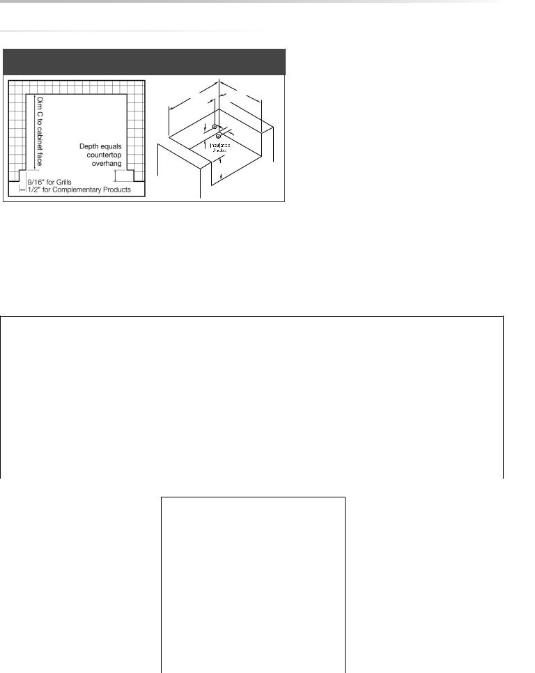
A 3 inch clearance is required behind the grill to allow the front hood to open.
The grill exhausts combustion products and cooking greases to the back. Never locate the grill where this exhaust will be difficult to clean.
3” (7.6 cm)
CLEARANCE TO COMBUSTIBLE MATERIALS
Minimum clearance from the sides and back of the grill to adjacent combustible construction below the counter top surface is 12” from the sides and 6 1/4” from the back of the hood.
Minimum clearance from sides and back of grill to adjacent combustible construction extending above the counter top surface is 12” from the sides and 6 1/4” from the back.
Do not use this appliance under unprotected overhead combustible surfaces.
A minimum of 6” of clearance is needed on the left side of the grill above the counter top for the motor and skewer.
If the grill is to be placed into a combustible enclosure, an approved insulated jacket is necessary and is available only from your Viking Range, LLC dealer. Insulated jackets have been designed and tested specifically for your grill.
INSTALLATION / USE & CARE | 7

SPECIFICATIONS & INSTALLATION
The guides, measurements and dimensions detailed below are designated to assist you with planning your outdoor kitchen.
NOTE: Due to continuing product innovation, specifications are subject to change without notice.
IMPORTANT: Please reference the Care & Use / Installation manual for details on gas plumbing requirements, electrical specifications and the proper installation of your outdoor kitchen equipment. This manual can be downloaded from our website at www.vikingrange.com.
GRILLS
MODEL |
A |
B |
C |
VQGI5301 |
29.00 |
10.88 |
24.50 |
|
|
|
|
VQGI5361 |
35.00 |
10.13 |
22.00 |
|
|
|
|
VQGI5421 |
41.00 |
10.88 |
24.50 |
|
|
|
|
VQGI5541 |
53.00 |
10.88 |
24.50 |
COMPLEMENTARY PRODUCTS
SIDE BURNERS
MODEL |
A |
B |
C |
|
VQGSB5131 |
12.13 |
10.63 |
24.50 |
|
|
|
|
|
|
VQGPB5201 |
19.00 |
10.63 |
22.00 |
|
WARMING DRAWERS |
|
|
|
|
MODEL |
A |
B |
C |
|
|
|
|
|
|
VQEWD5301 |
28.50 |
10.00 |
20.50 |
|
|
|
|
|
|
VQEWD4201 |
40.25 |
19.38 |
24.50 |
|
|
|
|
|
|
WITH INSULATED JACKET INSTALLED
MODEL |
A |
B |
C |
VIJ5301 |
36.00 |
11.63 |
26.50 |
|
|
|
|
VIJ5361 |
42.00 |
11.63 |
24.00 |
|
|
|
|
VIJ5421 |
48.00 |
11.63 |
26.50 |
|
|
|
|
VIJ5541 |
60.00 |
11.63 |
26.50 |
8 | INSTALLATION / USE & CARE
SPECIFICATIONS & INSTALLATION
COUNTER TOP NOTCH DETAIL
Only required if island counter top overhangs the face of the island
A |
C |
5” |
|
(12.7 cm) |
|
4.5” |
3” |
(11.4 cm) |
(7.6 cm) |
B
MODEL-SPECIFIC BTU OUTPUTS & MAX. RUNS FOR APPLIANCES
MODEL-SPECIFIC BTU OUTPUTS
MODEL |
H BURNER (Btu) |
ROTISSERIE (Btu) |
PROSEAR™ (Btu) |
TOTAL INPUT |
|
|
|
|
|
VQGI5301/VQGFS5301 (N/L)SS |
1 @ 25,000 |
1 @ 14,000 |
1 @ 21,000 |
60,000 Btu/Hr |
|
|
|
|
|
VQGI5361/ VQGFS5361 (N/L)SS |
2 @ 25,000 |
1 @ 14,000 |
1 @ 21,000 |
85,000 Btu/Hr |
|
|
|
|
|
VQGI5421/ VQGFS5421 (N/L)SS |
2 @ 25,000 |
1 @ 16,000 |
1 @ 21,000 |
87,000 Btu/Hr |
|
|
|
|
|
|
|
|
|
|
VQGI5541/ VQGFS5541 (N/L)SS |
3 @ 25,000 |
2 @ 14,000 |
1 @ 21,000 |
124,000 Btu/Hr |
|
|
|
|
|
MAXIMUM RUNS FOR ALL
APPLIANCES ON SUPPLY LINE
Run Length 3/4” |
Max BTU for all |
Pipe (in feet) |
Appliances on line |
|
|
10 |
360,000 |
|
|
20 |
245,000 |
|
|
30 |
198,000 |
|
|
40 |
169,000 |
|
|
50 |
150,000 |
|
|
60 |
135,000 |
|
|
70 |
123,000 |
|
|
80 |
115,000 |
|
|
INSTALLATION / USE & CARE | 9

DIMENSIONS
VQGI5301
 30"30” (76.2 cm)
11” (27.9 cm)
11"
9” (22.9 |
|
|
|
|
|
11”11" |
(27.9 cm) |
||
cm) |
|
|
|||||||
|
9" |
|
|
|
|
|
|
|
REAR |
|
|
|
|
|
|
|
|
||
|
|
|
|
|
|
|
|
|
|
|
|
1 |
2 |
|
|
|
1 |
(6.4 cm) |
|
|
|
|
"(6.4 cm) |
|
|
22½”/ " |
|
||
|
|
2½”/ |
|
|
|
|
MANIFOLD |
||
|
|
|
|
|
|
||||
|
|
|
|
|
|
Rear Manifold |
|||
LocationLOCATION
VQGFS5301
55¾” (141.6 cm)
553/4"
36½”36(921/2."7 cm) 30” (7630".2 cm)
|
|
|
|
|
|
|
11” |
|
|
|
|
|
|
11" |
|
|
|
|
|
|
|
|
(27.9 cm) |
36” |
|
|
|
|
|
|
|
(91.4 cm) |
|
|
|
|
35½” |
|
|
36" |
32" |
REAR CORD |
|
|
1 |
|
|
|
32” |
|
(90.235 /cm)2" |
||||
(81.3 cm) |
LOCATION |
|
|
|
|
||
|
|
31/8” |
|
|
3 |
|
|
|
|
3 /8" |
|
|
26¾”/4 |
|
|
|
|
(7.9 cm) |
|
|
(67.9 cm) |
|
|
|
|
7 (9.8 |
cm) |
|
|
|
|
|
|
87/8”/8" |
|
|
|
|
|
|
|
30” (7630".2 cm) |
|
|
2½” |
||
|
|
1 |
|
|
1 |
||
|
|
35¼”35(89/4.5" |
cm) |
|
2 /2" |
||
253/16” (64253./016cm)"
1414½”/ "
2
 1¾” (4.4 cm)
(36.8 cm)
13/4"
10½”
101/2"
(26.7 cm)
3"
21½”
(54.61 cm)  3” (7.6 cm)
21 /2"
253/8”
(2625.73/cm)8" 277/8”
(7027.87/cm)8"
|
|
|
|
|
|
|
|
|
|
|
14½” |
|
|
|
|
||
|
14 /2" |
|
|
|
|
|||
1¾” |
(36.8 cm) |
|
|
|
|
|||
|
|
|
|
|
|
|
|
|
13/4" |
|
|
|
|
|
|
||
(4.4 cm) |
|
|
|
6011/16” |
|
|||
|
|
8¾” |
|
(154.1 |
cm) |
|||
|
|
|
60 |
/16" |
|
|||
|
|
83/4" |
|
|
|
|
|
|
|
(22.2 cm) |
|
50” |
|
|
|
||
|
|
|
|
|
|
|
|
|
|
50" |
|
|
|
||||
|
|
|
(127.0 cm) |
|||||
GAS
EXIT
26¾”3/4"
(67.9 cm)
CORD
87/8"
25¼”
251/ "
10 | INSTALLATION / USE & CARE
DIMENSIONS
VQGI5361
36” (91.4 cm)
9” (22.9 cm)
 11/8” (2.9 cm)
VQGFS5361
61¾” (108.0 cm) 42½” (91.4 cm) 36” (91.4 cm)
36” |
|
|
(91.4 cm) |
REAR CORD |
|
|
32” |
|
|
LOCATION |
|
(81.3 cm) |
31/8” |
|
|
|
(7.9 cm) |
87/8” (9.8 cm)
 11” (27.9 cm)
  11” (27.9 cm)
2½” (6.4 cm)
Rear Manifold
Location
11” (27.9 cm)

35½” (90.2 cm)
26¾” (67.9 cm)
23½” (59.7 cm)
147/8” (37.8 cm)
1¾”  (4.4 cm)
97/8” (25.1 cm)
19” |
3” (7.6 cm) |
(48.3 cm) |
|
227/8” (58.1 cm)
253/8” (64.5 cm)
147/8” (37.8 cm)
1¾”  (4.4 cm)
87/16"
5811/16” (149.1 cm)
GAS 50”
EXIT (127.0 cm)
26¾” (67.9 cm)
INSTALLATION / USE & CARE | 11

DIMENSIONS
42” (106.7 cm)
9” (22.9 cm) |
11” (27.9 cm) |
11” (27.9 |
cm) |
|
|||
|
|
|
11" |
2½” (6.4 cm) |
2½” (6.4 cm) |
|
|
|
Rear Manifold |
|
|
|
Location |
|
|
VQGFS5421
67¾” (172.1 cm)
553/4"
48½”36(123/ ".2 cm) 42” (10630".7 cm)
|
|
|
|
|
|
|
|
11” |
|
|
|
|
|
|
|
|
|
11" |
|
|
|
|
|
|
|
|
(27.9 cm) |
|
|
36” |
|
|
|
|
35½” |
|
|||
|
|
|
|
(90.2 cm) |
|||||
(91.4 cm) |
|
|
|
||||||
36" |
32" |
|
|
|
|
|
|
|
|
|
32” |
|
26¾” |
|
|
|
|
||
(81.3 cm) |
|
|
|||||||
|
|
REAR CORD |
(67.9 cm) |
|
|||||
|
|
LOCATION |
13/16” |
|
|||||
|
|
|
|
(3.0 cm) |
|||||
|
|
63/16” |
|
|
|
|
|
|
|
|
|
(15.7 cm) |
|
|
|
|
2½” |
|
|
|
|
|
|
|
|
|
|
|
|
|
|
42” (106.7 cm) |
|
|
|
|
21/2" |
|
|
|
|
|
|
|
|
|
(6.4 cm) |
|
|
|
|
|
|
|
|
|
|
2111/8"” |
|
|
|
|
|
|
|
|
|
||
253/16” (6425.03/cm)16"
1414½”/ "
2
 1¾” (4.4 cm)
(36.8 cm)
13/4"
10½”
101/2"
(26.7 cm)
3"
21½”
(54.6 cm)  3” (7.6 cm)
253/8”
3/ "
(64.5 cm)8
277/8” 7
(70.8 cm)
|
|
|
|
|
|
|
|
|
|
|
14½” |
|
|
|
|
||
|
14 /2" |
|
|
|
|
|||
1¾” |
(36.8 cm) |
|
|
|
|
|||
|
|
|
|
|
|
|
|
|
13/4" |
|
|
|
|
|
|
||
(4.4 cm) |
|
|
|
6011/16” |
|
|||
|
|
8¾” |
|
(154.1 |
cm) |
|||
|
|
|
60 |
/16" |
|
|||
|
|
83/4" |
|
|
|
|
|
|
|
(22.2 cm) |
|
50” |
|
|
|
||
|
|
|
|
|
|
|
|
|
|
50" |
|
|
|
||||
|
|
|
(127.0 cm) |
|||||
GAS
EXIT
26¾”3/4"
(67.9 cm)
CORD
87/8"
25¼”
251/4"
(64.1 cm)
12 | INSTALLATION / USE & CARE

DIMENSIONS
VQGI5541
54” (137.2 cm)
25½”
|
|
|
|
|
|
|
3 |
|||||
|
|
|
|
|
|
|
|
|
|
|
(6425.8/cm)16" |
|
|
|
|
|
|
|
|
|
|
1413/16” |
|
||
|
|
|
|
|
|
|
|
|
14 /2" |
|
||
|
|
|
|
|
|
1¾” |
|
(37.6 cm) |
|
|||
|
|
|
|
|
|
|
|
|
|
|
|
|
|
|
|
|
|
(4.4 cm) |
|
|
|
|
|
|
|
9” (22.9 cm) |
11” (27.9 cm) |
|
|
|
13/4" |
|
|
|||||
|
|
|
|
|
|
|
||||||
|
|
|
|
|
|
|
103/16” |
|
||||
|
11” (27.9 |
cm) |
|
|
|
|
|
|
|
|
||
|
|
|
|
|
|
|
101/2" |
|
||||
|
|
11" |
|
|
|
|
|
|
(25.9 cm) |
|||
2½” (6.4 cm) |
2½” (6.4 cm) |
|
|
|
|
|
|
|
|
|
||
|
|
|
|
3" |
|
|
||||||
|
Rear Manifold |
|
21½” |
|
|
|
|
|
|
|
|
|
|
Location |
|
|
|
|
|
3” (7.6 cm) |
|||||
|
|
(54.6 cm) |
|
|
|
|||||||
|
|
|
|
253/8” |
|
|
|
|
|
|
|
|
|
|
|
|
3/8" |
|
|
|
|
|
|
|
|
|
|
|
|
(26.7 cm) |
|
|
|
|
|
|
|
|
|
|
|
|
277/8” |
7 |
|
|
|
|
|
|
|
|
|
|
|
|
|
|
|
|
|
|
||
|
|
|
(70.8 cm) |
|
|
|
|
|
|
|||
VQGFS5541
|
|
|
|
|
|
|
|
|
|
|
|
|
|
|
|
|
|
|
|
|
|
|
|
|
|
|
|
|
|
|
|
|
|
|
|
79¾” (202.6 cm) |
|
|
|
|
|
|
|
|
|
|
|
|
|
|
|
|
|
|
|
|
|
|
|
|
|
|
|
|
|
|
60½” (153.7 cm) |
|
|
|
|
|
|
|
|
|
|
|
|
|
|
|
|
|
|
|
|
|
|
|
|
|
|
|
|
|
|
54” (137.2 cm) |
|
|
|
|
|
|
|
|
|
|
|
|
|
|
|
|
|
|
|
|
|
|
|
|
|
|
|
|
|
|
|
|
|
|
|
|
|
|
|
|
|
|
|
|
1413/16” |
|
|
|
|
|
|
|||||
|
|
|
|
|
|
|
|
|
|
|
|
|
|
|
|
|
|
|
14 /2" |
|
|
|
|
|
|
|||||
|
|
|
|
|
|
|
|
|
|
|
|
|
|
|
|
|
1¾” |
|
(37.6 cm) |
|
|
|
|
|
|
|||||
|
|
|
|
|
|
|
|
|
|
|
|
|
|
|
|
|
|
|
|
|
|
|
|
|
|
|
|
|
|
|
|
|
|
|
|
|
|
|
|
|
|
|
|
|
|
|
|
|
13/4" |
|
|
|
|
|
|
|
|
|
|
||
|
|
|
|
|
|
|
|
|
|
|
|
|
|
|
|
(4.4 cm) |
|
|
|
|
|
|
|
|
6011/16” |
|
||||
|
|
|
|
|
|
|
|
|
|
|
|
|
|
|
|
|
|
|
|
85/8” |
|
|
|
(154.1 |
cm) |
|||||
|
|
|
|
|
|
|
|
|
|
|
|
|
11” |
|
|
|
|
|
|
|
60 |
/16" |
|
|||||||
|
|
|
|
|
|
|
|
|
|
|
|
|
|
|
|
|
|
|
3 |
|
|
|
|
|
|
|
|
|||
|
|
|
|
|
|
|
|
|
|
|
|
|
11" |
|
|
|
|
|
|
8 |
|
/4" |
|
|
|
|
|
|
|
|
|
|
|
|
|
|
|
|
|
|
|
|
(27.9 cm) |
|
|
|
|
|
(21.9 cm) |
|
|
|
|
|
|
||||||
|
|
|
|
|
|
|
|
|
|
|
|
|
|
|
|
|
|
|
|
|
|
|
|
|
|
|||||
|
|
|
|
|
|
|
|
|
|
|
|
|
|
|
|
|
|
|
|
|
|
|
|
|
50” |
|
|
|
||
|
|
|
|
|
|
|
|
|
|
|
|
|
|
|
|
|
|
|
|
|
|
|
50" |
|
|
|
|
|||
36” |
|
|
|
|
|
|
|
|
|
|
|
|
|
|
|
|
GAS |
|
(127.0 cm) |
|
|
|||||||||
|
|
|
|
|
|
|
|
|
|
|
|
|
|
|
|
|
|
|
|
|
|
|
|
|
||||||
(91.4 cm) |
|
|
|
|
|
|
353/16” |
|
|
|
|
|
|
|
|
|
|
|
|
|
|
|
|
|||||||
|
REAR CORD |
|
|
|
|
|
|
|
|
|
EXIT |
|
|
|
|
|
|
|
|
|
||||||||||
|
|
32” |
|
(89.4 cm) |
|
|
|
|
|
|
|
269/16”3 |
|
|
|
|
|
|
||||||||||||
|
(81.3 cm) |
LOCATION |
|
|
|
|
|
|
|
|
|
|
|
|
26 |
/4" |
|
|
|
|
|
|
|
|||||||
|
|
|
|
31/8” |
|
269/16” |
|
|
|
|
|
|
|
|
(67.5 |
|
cm) |
|
|
|
|
|
|
|
||||||
|
|
|
|
|
|
|
|
|
|
|
|
|
|
|
|
|
|
|
|
|
|
|||||||||
|
|
|
|
(7.9 cm) |
|
|
|
|
|
|
|
|
CORD |
|
|
|
|
|
|
|
|
|
||||||||
|
|
|
|
|
|
|
(67.5 cm) |
|
|
|
|
|
|
|
|
|
|
|
|
|
|
|
|
|
|
|
|
|||
|
|
|
|
87/8” (9.8 cm) |
REAR |
|
|
|
|
|
|
87/8" |
|
|
|
|
|
|
|
|
|
|
||||||||
|
|
|
|
|
|
|
|
|
|
|
|
|
|
|
|
|
|
|
||||||||||||
|
|
|
|
|
54” (137.2 cm) |
|
2½” |
|
|
|
|
|
|
|
|
|
|
|
|
|
|
|
|
|
||||||
|
|
|
|
|
|
|
|
|
|
|
|
|
|
|
|
|
|
|
|
|
|
|||||||||
|
|
|
|
|
|
|
GAS EXIT |
|
|
|
25¼” |
|
|
|
|
|
|
|
|
|
|
|
|
|
|
|||||
|
|
|
|
|
59¼” (150.5 cm) |
LOCATION |
21/2" |
|
|
251/4" |
|
|
|
|
|
|
|
|
|
|
|
|
|
|
||||||
|
|
|
|
|
(6.4 cm) |
|
|
(64.1 cm) |
|
|
|
|
|
|
|
|
|
|
|
|
|
|
||||||||
|
|
|
|
|
|
|
|
|
|
|
|
|
181/8” |
|
|
|
|
|
|
|
|
|
|
|
|
|
|
|
|
|
|
|
|
|
|
|
|
|
|
|
|
|
15 /8" |
|
|
|
|
|
|
|
|
|
|
|
|
|
|
|
|
|
|
|
|
|
|
|
|
|
|
|
|
|
|
(46.0 cm) |
|
|
|
|
|
|
|
|
|
|
|
|
|
|
|
|
||
|
|
|
|
|
(DOORS OPEN AT 90°) |
|
|
|
|
|
|
|
|
(DOORS OPEN AT 90°) |
|
|
|
|
|
|
|
|
|
|||||||
INSTALLATION / USE & CARE | 13
UNPACKING & ASSEMBLY
The grill arrives nearly ready to use and requires only minor assembly.
By carefully following the uncrating and unpacking steps, you will improve your first experience with the grill.
Shipping weight on smaller units is app. 300 pounds and larger units may weigh over 500 pounds.
WARNING:
EXCESSIVE WEIGHT HAZARD!
Use two or more people to move or install this unit. Failure to follow this instruction can result in back or other personal injuries.
CRATE & CARTON
•IMPORTANT! Do not remove staples around the top of the carton. These staples hold a wooden pallet in place inside the carton that protects the unit from damage. Removing these staples may cause the pallet to fall on the top of grill.
How to Remove the Carton
•Cut the main strap holding the grill to the pallet.
•Remove the staples at the bottom of the carton.
•Lift off the carton.
•With assistance, remove the grill from the pallet and place into desired location.
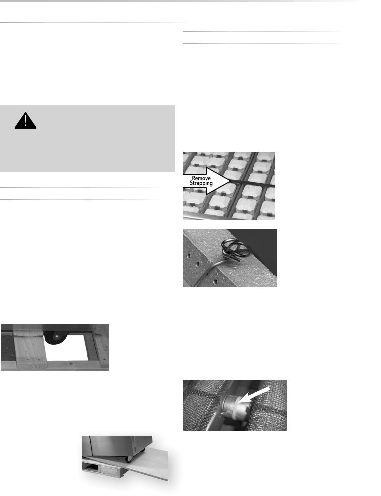
The wheels sit down in the gaps of the shipping crate so that
Grill will not slide directly off pallet.
the grill can sit safely and solidly on the crate during shipping. The grill cannot be slid directly off of the pallet.
One way to safely move the grill off of the pallet is by lifting one end of the grill high enough to place a ramp under the wheel and then lift the other end while rolling the grill off of the pallet.
INTERIOR PACKING
Viking Range, LLC uses sturdy tie-down cables and straps to ensure your grill arrives at your home in the same condition that it left our factory. BE SURE YOU HAVE REMOVED ALL TIE DOWNS BEFORE USING YOUR GRILL.
•Remove the white accessory box and wood packing, the grill racks, and remove any loose items from the firebox.
•Carefully cut the cable ties securing the warming rack and rotisserie spit (if equipped).
•Cut the strapping that secures the briquette trays and carefully lift them out, front first.
Make sure you remember to remove the tie-downs on the burners.
•On ProSear™ models, cut and remove ties from the burner partition on the left side of the ProSear™ burner.
•Ensure that all burners are properly seated on the burner valve orifice and sitting level with the legs in the frame slots and no side-to-side movement.
14 | INSTALLATION / USE & RE
 Loading...