


VT2205LED
VT2405LED
LCD TV
- User Guide
- Guide de l’utilisateur
- Bedienungsanleitung
- Guida dell’utente
Model No. : VS13749-1E
VS13750-1E

Contents |
|
Compliance Information .................................................................................................... |
1 |
Important Safety Instructions............................................................................................. |
2 |
Declaration of RoHS Compliance...................................................................................... |
3 |
Copyright Information......................................................................................................... |
4 |
Product Registration.......................................................................................................... |
4 |
Antenna Installation Instructions........................................................................................ |
5 |
Cleaning the LCD TV......................................................................................................... |
5 |
Quick Start Guide |
|
1. Please read these instructions ...................................................................................... |
6 |
What's in the Quick Start Guide?.................................................................................. |
6 |
What's in the User Manual?.......................................................................................... |
6 |
2. Package contents.......................................................................................................... |
6 |
3. Select and prepare the installation location................................................................... |
7 |
4. Installing the Base.......................................................................................................... |
8 |
5. Disconnecting the base and arm................................................................................... |
9 |
6. Adjust the viewing angle ............................................................................................... |
10 |
7. Connect the antenna cable............................................................................................ |
10 |
8. Connect the power cable............................................................................................... |
11 |
9. Activate the remote control ........................................................................................... |
12 |
Installing batteries......................................................................................................... |
12 |
Battery safety notice..................................................................................................... |
12 |
Using the remote control .............................................................................................. |
13 |
10. Initialize your TV.......................................................................................................... |
14 |
11.View the TV programs................................................................................................... |
14 |
Care and cleaning information...................................................................................... |
15 |
What's next?................................................................................................................. |
15 |
User Manual |
|
Getting to know your TV ................................................................................................... |
16 |
Front view..................................................................................................................... |
16 |
Rear view...................................................................................................................... |
17 |
Getting to know the remote control ................................................................................... |
19 |
Remote control.............................................................................................................. |
19 |
Using the remote control ................................................................................................... |
23 |
Power on, off and standby............................................................................................ |
23 |
Adjusting sound setting................................................................................................. |
23 |
Changing channels....................................................................................................... |
24 |
Adjusting backlight........................................................................................................ |
25 |
Adjusting aspect ratio ................................................................................................... |
25 |
ViewSonic |
VT2205LED/VT2405LED |
ENGLISH

ENGLISH
Using the Teletext function............................................................................................ |
27 |
Connecting video and audio signals.................................................................................. |
29 |
Input options................................................................................................................. |
29 |
Connecting the Composite Video input......................................................................... |
29 |
Connecting the SCART input........................................................................................ |
30 |
Connecting the Component Video input....................................................................... |
30 |
Connecting the S-Video input....................................................................................... |
31 |
Connecting the PC input............................................................................................... |
31 |
Connecting the DVI input.............................................................................................. |
32 |
Connecting the HDMI input .......................................................................................... |
32 |
Connecting the USB input ........................................................................................... |
33 |
Connecting the headset audio output .......................................................................... |
33 |
Connecting to A/V Device with SPDIF input................................................................. |
34 |
OSD (On-Screen Display) menu........................................................................................ |
35 |
OSD structure............................................................................................................... |
35 |
Navigating the OSD menu............................................................................................ |
37 |
Operations in the OSD menu........................................................................................ |
37 |
PICTURE menu............................................................................................................ |
38 |
SOUND menu............................................................................................................... |
41 |
TIME menu................................................................................................................... |
42 |
OPTION menu.............................................................................................................. |
43 |
LOCK menu.................................................................................................................. |
45 |
CHANNEL menu........................................................................................................... |
46 |
Connecting CI(Common Interface) card....................................................................... |
47 |
Media Play - USB Device................................................................................................... |
48 |
Precautions when using a USB device......................................................................... |
48 |
Media Screen Display................................................................................................... |
49 |
Viewing Photo or Slide Show........................................................................................ |
50 |
Display the Text............................................................................................................. |
51 |
Other Information |
|
VT2205LED Dimensions.................................................................................................... |
52 |
VT2405LED Dimensions.................................................................................................... |
53 |
Specifications..................................................................................................................... |
54 |
Supported PC (D-Sub/DVI) input signal resolutions..................................................... |
55 |
Supported Component Video input signal resolutions.................................................. |
56 |
Supported HDMI input signal resolutions..................................................................... |
56 |
Setting up appropriate output resolution on PC............................................................ |
57 |
Safety Precautions........................................................................................................ |
58 |
Troubleshooting................................................................................................................. |
59 |
Customer Support.............................................................................................................. |
60 |
Limited Warranty................................................................................................................ |
61 |
ViewSonic |
VT2205LED/VT2405LED |
Compliance Information
CE Conformity for European Countries
The device complies with the EMC Directive 2004/108/EC and Low Voltage Directive 2006/95/EC.
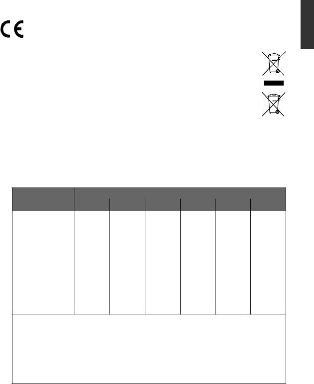
Following information is only for EU-member states:
The mark shown to the right is in compliance with the Waste Electrical and Electronic Equipment Directive 2002/96/EC (WEEE).
The mark indicates the requirement NOT to dispose the equipment as unsorted municipal waste, but use the return and collection systems according to local law.
If the batteries, accumulators and button cells included with this equipment, display the chemical symbol Hg, Cd, or Pb, then it means that the battery has a heavy metal content of more than 0.0005% Mercury or more than, 0.002% Cadmium, or more than 0.004% Lead.
ENGLISH
Marking for the content condition of chemicals
Coarse |
|
|
Chemical Substance Table |
|
|
|
Classification |
Pb |
Hg |
Cd |
Cr6+ |
PBBs |
PBDEs |
|
|
|
|
|
|
|
Front bezel |
¡ |
¡ |
¡ |
¡ |
¡ |
¡ |
|
|
|
|
|
|
|
Back-cover |
¡ |
¡ |
¡ |
¡ |
¡ |
¡ |
|
|
|
|
|
|
|
LCD panel |
¡ |
¡ |
¡ |
¡ |
¡ |
¡ |
Power PCBA |
exempted |
¡ |
¡ |
¡ |
¡ |
¡ |
|
|
|
|
|
|
|
Main PCBA |
exempted |
¡ |
¡ |
¡ |
¡ |
¡ |
|
|
|
|
|
|
|
Keypad-PCBA |
¡ |
¡ |
¡ |
¡ |
¡ |
¡ |
|
|
|
|
|
|
|
Stand |
¡ |
¡ |
¡ |
¡ |
¡ |
¡ |
|
|
|
|
|
|
|
Power cord |
¡ |
¡ |
¡ |
¡ |
¡ |
¡ |
|
|
|
|
|
|
|
I/O cable |
¡ |
¡ |
¡ |
¡ |
¡ |
¡ |
*:PWBA consisted of bare printed circuit board, soldering and its surface-mounted elements, such as resistors, capacitors, arrays, connectors, chips, etc.
NOTE 1: The “¡”indicates that the percentage content of the substance to be calculated is not exceeding the reference percentage content of EU RoHS directive (2002/95/ EC).
NOTE 2: The “exempted” item means that the specified chemical substance corresponds to the items exempted by the EU RoHS directive (2002/95/EC).
NOTE 3: The content of Mercury: none of part exceeding 0.1%
ViewSonic |
1 |
VT2205LED/VT2405LED |

ENGLISH
Important Safety Instructions
1.Read these instructions completely before using the equipment.
2.Keep these instructions in a safe place.
3.Heed all warnings.
4.Follow all instructions.
5.Do not use this equipment near water. Warning: To reduce the risk of fire or electric shock, do not expose this apparatus to rain or moisture.
6.Clean with a soft, dry cloth. If further cleaning is required, see “Cleaning the LCD TV” in this guide for further instructions.
7.Do not block any ventilation openings. Install the equipment in accordance with the manufacturer’s instructions.
8.Do not install near any heat sources such as radiators, heat registers, stoves, or other devices
(including amplifiers) that produce heat.
9.Do not attempt to circumvent the safety provisions of the polarized or grounding-type plug. A polarized plug has two blades with one wider than the other. A grounding type plug has two blades and a third grounding prong. The wide blade and the third prong are provided for your safety. If the plug does not fit into your outlet, consult an electrician for replacement of the outlet.
10.Protect the power cord from being tread upon or pinched, particularly at the plug, and the point where if emerges from the equipment. Be sure that the power outlet is located near the equipment so that it is easily accessible.
11.Only use attachments/accessories specified by the manufacturer.
12. Use only with a cart, stand, tripod, bracket, or table specified by the manufacturer,


 or sold with the apparatus. When a cart is used, use caution when moving the cart/


 apparatus combination to avoid injury from tip-over.
13.Unplug this equipment when it will be unused for long periods of time.
14.Refer all servicing to qualified service personnel. Service is required when the unit has been damaged in any way, such as: if the power-supply cord or plug is damaged, if liquid is spilled onto or objects fall into the unit, if the unit is exposed to rain or moisture, or if the unit does not operate normally or has been dropped.
15.This product is only to perform the useful function of entertainment and visual display tasks are excluded.
ViewSonic |
2 |
VT2205LED/VT2405LED |

Declaration of RoHS Compliance
This product has been designed and manufactured in compliance with Directive 2002/95/EC of the European Parliament and the Council on restriction of the use of certain hazardous substances in electrical and electronic equipment (RoHS Directive) and is deemed to comply with the maximum concentration values issued by the European Technical Adaptation Committee (TAC) as shown below:
Substance |
Proposed Maximum |
Actual Concentration |
|
Concentration |
|||
|
|
||
|
|
|
|
Lead (Pb) |
0.1% |
< 0.1% |
|
|
|
|
|
Mercury (Hg) |
0.1% |
< 0.1% |
|
Cadmium (Cd) |
0.01% |
< 0.01% |
|
|
|
|
|
Hexavalent Chromium (Cr6+) |
0.1% |
< 0.1% |
|
Polybrominated biphenyls (PBB) |
0.1% |
< 0.1% |
|
Polybrominated diphenyl ethers (PBDE) |
0.1% |
< 0.1% |
Certain components of products as stated above are exempted under the Annex of the RoHS Directives as noted below:
Examples of exempted components are:
1.Mercury in compact fluorescent lamps not exceeding 5 mg per lamp and in other lamps not specifically mentioned in the Annex of RoHS Directive.
2.Lead in glass of cathode ray tubes, electronic components, fluorescent tubes, and electronic ceramic parts (e.g. piezoelectronic devices).
3.Lead in high temperature type solders (i.e. lead-based alloys containing 85% by weight or more lead).
4.Lead as an allotting element in steel containing up to 0.35% lead by weight, aluminium containing up to 0.4% lead by weight and as a cooper alloy containing up to 4% lead by weight.
ENGLISH
ViewSonic |
3 |
VT2205LED/VT2405LED |

ENGLISH
Copyright Information
Copyright © ViewSonic Corporation, 2010. All rights reserved.
ViewSonic, the three birds logo, OnView, ViewMatch, and ViewMeter are registered trademarks of ViewSonic Corporation.
Disclaimer:ViewSonic Corporation shall not be liable for technical or editorial errors or omissions contained herein; nor for incidental or consequential damages resulting from furnishing this material, or the performance or use of this product.
In the interest of continuing product improvement, ViewSonic Corporation reserves the right to change product specifications without notice. Information in this document may change without notice.
No part of this document may be copied, reproduced, or transmitted by any means, for any purpose without prior written permission from ViewSonic Corporation.
Product Registration
To meet your future needs, and to receive any additional product information as it becomes available, please register your product on the Internet at: www.viewsonic.com.
For Your Records
Product Name: VT2205LED/VT2405LED ViewSonic LCD TV
Model Number: VS13749-1E(VT2205LED)/VS13750-1E (VT2405LED) Document Number: VT2205LED-1E_UG_ENG Rev. 1A 07-15-10
VT2405LED-1E_UG_ENG Rev. 1A 07-15-10 Serial Number: _________________________________
Purchase Date: _________________________________
Product disposal at end of product life
ViewSonic is concerned about the preservation of our environment. Please dispose of this product properly at the end of its useful life. Your local waste disposal company may provide information about proper disposal.
ViewSonic |
4 |
VT2205LED/VT2405LED |

Antenna Installation Instructions
1. Outdoor Antenna Grounding
If an outside antenna or cable system is connected to the product be sure the antenna or cable system is grounded so as to provide some protection against voltage surges and built-up static charges, Article 810 of the National Electrical Code, ANSI/NFPA 70, provides information with regard to proper grounding of the mast and supporting structure, grounding of the lead-in wire to an antenna discharge unit, connection to grounding electrodes, and requirements for the grounding electrode.
2.Lightning
For added protection for this product during a lightning storm, or when it is left unattended and unused for long periods of time, unplug it from the wall outlet and disconnect the antenna or cable system. This will prevent damage to the product due to lightning and power-line surges. Do not disconnect the antenna or the power cord during a heavy storm lighting may strike while you are holding the cable cord, causing serious injury; turn off your LCD TV and wait for the weather to improve.
3.Power Lines
An outside antenna system should not be located in the vicinity of overhead power lines or other electric light or power circuits, or where it can fall into such power lines or circuits, When installing an outside antenna system, extreme care should be taken to keep from touching such power lines or circuits as contact with them might be fatal.
Antenna
Ground clamp
Antenna discharge unit
Electric service equipment
Ground clamps
Grounding conductors Power service grounding electrode system
Cleaning the LCD TV
•Make sure the LCD TV is turned off.
•Never spray or pour any liquid directly onto the screen or case.
To clean the screen:
1.Wipe the screen with a clean, soft, lint-free cloth. This removes dust and other particles.
2.If still not clean, apply a small amount of non-ammonia, non-alcohol based glass cleaner onto a clean, soft, lint-free cloth, and wipe the screen.
To clean the case:
1.Use a soft, dry cloth.
2.If still not clean, apply a small amount of a non-ammonia, non-alcohol based, mild non-abrasive detergent onto a clean, soft, lint-free cloth, then wipe the surface.
Disclaimer
ViewSonic does not recommend the use of any ammonia or alcohol-based cleaners on the LCD TV screen or case. Some chemical cleaners have been reported to damage the screen and/or case of the LCD TV. ViewSonic will not be liable for damage resulting from use of any ammonia or alcohol-based cleaners.
ViewSonic |
5 |
VT2205LED/VT2405LED |
ENGLISH
ENGLISH
Quick Start Guide
1. Please read these instructions
Congratulations. You have a state-of-the-art flat widescreen digital LCD TV which should provide you with years of viewing pleasure. Please take a few minutes to read these quick start instructions through before installing and using the TV.
What's in the Quick Start Guide?
Section 1 contains the Quick Start Guide which provides you with enough information to setup the TV. This is section 1.
What's in the User Manual?
Section 2 contains the User Manual which details the features and functions of the TV, and provides product specifications and troubleshooting information for your further assistance.
The User Manual also describes how to customise the TV settings so that you can gain the best viewing experience possible to suit your preferences and viewing environment.
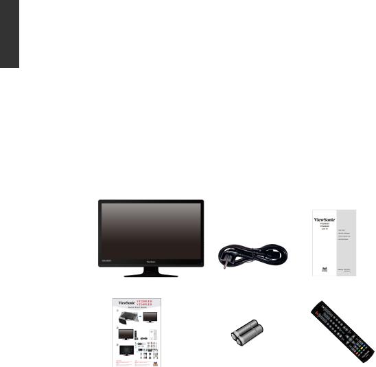
2. Package contents
Unpack the TV and check that all the following items are included:
LCD TV (x1) |
Power cord (x1) |
User Manual (x1) |
|
AAA battery |
Remote |
Quick Start Guide (x1) |
(x2) |
control (x1) |
The type of power cable supplied may differ from that illustrated, dependant upon your region of purchase.
If any item is missing or damaged, contact your place of purchase immediately and notify them of the discrepancy. Please keep the product documentation in a safe place for later reference.
Dispose of packaging wisely:
•The cardboard carton can be recycled.
•Do not leave plastic bags within reach of young children or babies.
•Check that you haven't left an accessory inside the packaging, befored discarding.
For the primary safety of yourself and others, this TV should be handled with care to avoid damage to it or to persons which come into contact with it.
All LCD screens have a very thin protective layer of glass which is liable to marking or scratching, and cracking if struck or pressured. The liquid crystal substrate is also liable to damage under excessive force or extreme temperatures. Please handle with care.
ViewSonic |
6 |
VT2205LED/VT2405LED |
3. Select and prepare the installation location
In order to prevent potential dangers and prolong the service life of the TV, please observe the following points when installing, operating and cleaning the TV.
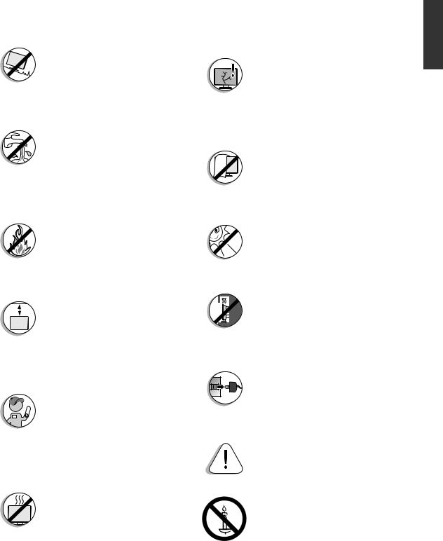
Do NOT place the display on an uneven, sloping or unstable surface where it may fall and cause damage to itself or others.
Have a qualified technician secure the display where it is placed in case there is an earthquake.
Do NOT place the display near water, like a spa or pool, or in a position which will allow the splashing or spraying of water onto the display, like in front of an open window where rain water may enter.
Do NOT place the display near or above sources of heat, such as radiators, heaters, fuel stoves and other heat-generating items
(including audio amplifiers).
Otherwise heat may cause damages to the outer casing as well as the components inside.
If wall mounting, allow appropriate space on top for attaching the display to the wall bracket.
If wall mounting, have a suitable qualified and experienced tradesperson mount it safely. Use only a recommended display wall bracket for this model display and  ensure that the mounting bracket (optional accessory) is securely screw fixed to the wall structure, and not just the wall render, lining or cladding. Ensure the bracket is level horizontally. Do not glue the bracket to the wall.
Do NOT place the display in an enclosed place without allowing for ventilation.
All Liquid Crystal Display (LCD) screens have a very thin protective layer of glass which is liable to marking or scratching, and cracking if struck or pressured.
The liquid crystal substrate is also liable to damage under excessive force or extreme temperatures.
Please handle with care.
Do NOT cover or block the vents and openings while the display is switched on, as the heat may accumulate inside the display and result in danger.
Do NOT place the display in direct sun or where direct sun or spot  lighting will shine onto the display, as the heat may damage the display and the bright light will make viewing the display more difficult than necessary.
If recessed into a wall opening, you must leave appropriate free space both top and bottom for mounting and removing the display.
When installing the display, connect the power cord to socket-outlet which must be provided near the display and easily accessible. If a fault should occur during operation of the unit, operate the disconnect device to switch the power supply off, or disconnect the power cord.
Observe all warnings and cautions as labelled on the display.
WARNING
To prevent the spread of fire, keep candles or other open flames away from this product at all times.
ENGLISH
ViewSonic |
7 |
VT2205LED/VT2405LED |
ENGLISH
4. Installing the Base
Important safety notes
Please pay attention to the following before installing:
•For safety reasons, it is recommended that the installation be carried out by at least two adult persons.
•The LCD panel of the display is extremely fragile and subject to damages easily.
Avoid touching the LCD panel when installing or moving the display, and take precautions not be let any objects come into contact with the panel. It is
recommended that you use a soft, clean and lint-free towel to protect the display when installing.
•Pay attention to the stability of the location where the display will be placed.
Follow the instructions below to install the TV stand:
Open the box, and make sure all necessary parts are in the box. The package contains:
Stand
LCD TV
1.Cover an even stable surface with a soft cloth. Place the LCD TV unit face down on the cloth. Fit the stand onto the bottom of the LCD TV unit as shown:
2. Then push until stand into the LCD TV’s stand socket.
ViewSonic |
8 |
VT2205LED/VT2405LED |
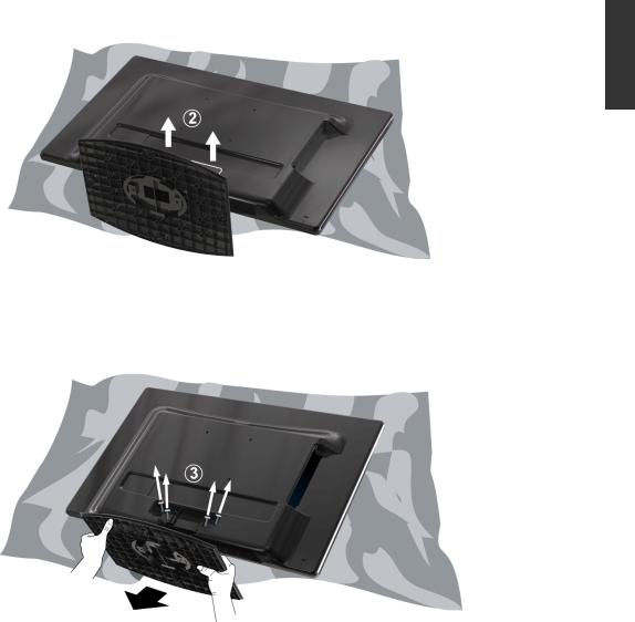
5.Disconnecting the base and arm
1.Cover an even stable surface with a soft cloth. Place the LCD Display unit face down on the cloth. Fit the stand onto the bottom of the LCD Display unit as shown:
ENGLISH
2.Pull the hinge cover on the arm upward to remove it, as shown above by (2).
3.Remove the 4 screws from the hinge, then pull off the arm slowly, as shown below by (3).
4.Removal of the arm from the stand base completed.
ViewSonic |
9 |
VT2205LED/VT2405LED |
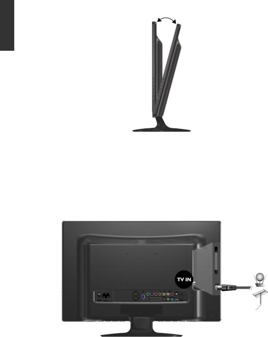
6. Adjust the viewing angle
This display is equipped with a adjustable base. If necessary, turn the display screen to an appropriate angle (maximum 20 degrees up and down) for more comfortable viewing.
ENGLISH
7. Connect the antenna cable
Connect a TV antenna cable fly-lead from your TV antenna system or Cable TV (CATV) to the TV input on the TV. Check to make sure that the cable connection is firmly in place.
•Apoor quality TV signal will produce a poor picture and/or sound on your TV. For high quality picture and sound ,you will need a high quality TV signal.
Depending upon your location, for best TV signal reception, you should have a properly aligned outdoor TV antenna system. If need be, consult a professional antenna specialist.
ViewSonic |
10 |
VT2205LED/VT2405LED |
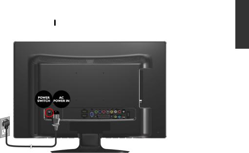
8. Connect the power cable
1. |
Locate the power cable from the packaging, and plug the appropriate end into the AC |
|
|
IN socket on the rear of the TV (as illustrated below). |
ENGLISH |
2. |
Connect the other end into an appropriate wall power outlet, and flip the main power |
|
|
switch on the TV to the ON ( ) position. The TV will enter standby mode and the |
|
|
|
power indicator (on the front lower right) will light up orange.
• The type of power cable plug and socket illustrated may differ from the type used in your region.
•Only use an appropriate power cable for your region. Never use a power cable which appears damaged or frayed. Never change the plug type on a power cable. Be aware of total loading when using extension cords or multiple outlet power boards.
WARNING:
This TV has been engineered and manufactured with the highest priority on safety, however, IMPROPER HANDLING OR USE CAN RESULT IN POTENTIAL ELECTRICAL SHOCK OR FIRE HAZARD. Please handle this TV with care. If damaged, turn off the power and unplug the power cable from the TV. Please refer the troubleshooting on page 59.
ViewSonic |
11 |
VT2205LED/VT2405LED |
ENGLISH
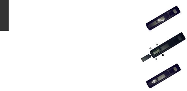
9. Activate the remote control
Installing batteries
1.Turn the remote control to reveal its back side, and open the lid of the battery compartment.
2.Insert the batteries (supplied) ensuring that the positive and negative marked battery terminals match the (+) and (-) marks in the battery compartment. Note that these batteries are provided for your convenience so that you can operate the display straight away. You should replace them as soon as possible.
3.Refit the lid of the battery compartment.
Battery safety notice
The use of the wrong type of batteries may cause chemical leaks and/or explosion. Please note the following:
•Always ensure that the batteries are inserted with the positive and negative terminals in the correct direction as shown in the battery compartment.
•Different types of batteries have different characteristics. Do not mix different types.
•Do not mix old and new batteries. Mixing old and new batteries will shorten battery life and/or cause chemical leaks from the old batteries.
•When batteries fail to function, replace them immediately.
•Chemicals which leak from batteries may cause skin irritation. If any chemical matter seeps out of the batteries, wipe it up immediately using a dry cloth.
•Due to varying storage conditions, the battery life for the batteries included with your TV may be shortened. Replace them within 3 months or as soon as you can after initial use.
ViewSonic |
12 |
VT2205LED/VT2405LED |
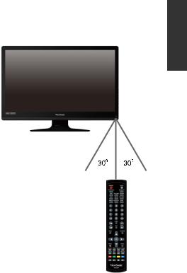
Using the remote control
1.Point and aim the top front of the remote
control directly at the display when pressing the buttons.
2.The remote control must be held at an angle within 30 degrees of the display's remote control sensor window to function correctly. The distance between the remote control and the sensors should not exceed 5 meters.
3.Do not cover the sensor window on the front of the display (below the power indicator lamp), or place objects in front of it which will block the direct line of sight between the remote control and the sensor window on the display.
• Do not let the remote control become wet, or
place it in humid environments (like bathrooms.)
•If the remote control sensor window on the display is in direct sunlight or strong light, the remote control may not operate properly. In this situation, change the light source or readjust the angle of your display, or operate the remote control from a location closer to the remote control sensor window on the display.
ENGLISH
ViewSonic |
13 |
VT2205LED/VT2405LED |
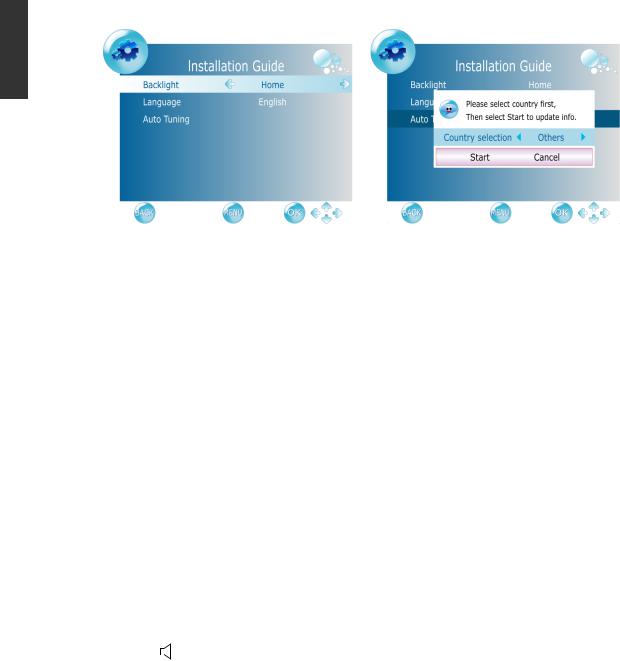
10. Initialize your TV
Press Power button on the remote control. the TV will turn on and the power indicator will light up blue. When first turned on (and until tuned), the Initial Menu will display:
ENGLISH
Before you can use your TV to view TV programs, you need to let it search for and tune TV station programs appropriate to your region. This process only needs to be done when the TV is newly installed, or whenever you install it in OSD menu for convenience of operation.
1.When Backlight is highlighted, use the ◄ or ► buttons to adjust the backlight.
2.Press ▼ button to select Language, use the ◄ or ► buttons to select the language displayed on the menu.
3.Press ▼ button to select Auto Tuning and press the OK button.
4.Press ◄ or ► to select the Country where you operate the TV, then select Start and
press OK. The Auto Tuning automatically creates a list of receivable channels. Press the BACK button at any time to interrupt the memorization process. (The list cannot be created if interrupted)
11.View the TV programs
•Press PROG▲ or PROG▼ on the remote control to sequentially cycle through your TV channels.
•To select a singleor double-digit channel, press the corresponding channel selection buttons on the remote control. For example, to select channel 8, press 0 and 8 on the remote control.
•Press VOL on the remote control to increase volume. The volume indicator will increase in length as volume rises.
•Press  MUTE on the remote control to turn off the sound temporarily.
Press  MUTE once more, or press VOL
 or VOL
 to restore the sound level.
• You can press RETURN on the remote control to quickly return to the previous viewed channel.
ViewSonic |
14 |
VT2205LED/VT2405LED |

Care and cleaning information
• Always turn off the display and disconnect it from the mains power before cleaning.
• Do NOT use cream, liquid, aerosol or spray cleaners. Use only a slightly damp well
wrung-out (drip-free) and lint-free, clean soft cloth and lightly wipe the display. |
ENGLISH |
|
If necessary, use a pH-neutral liquid dish-washing detergent diluted with water on a |
||
|
||
separate clean lint-free cloth to remove oil or grease marks. Wipe over again with a |
|
|
cleandry lint-free cloth to remove any smear marks. |
|
|
• Under close examination and in certain circumstances, you may notice that a few |
|
|
non-active pixels appear on the screen as a fiixed point of colour. Please note that this |
|
|
does not affect the performance of your product as it is usually not visible at normal |
|
|
viewing distances. |
|
|
• If the display is not going to be used for an extended period of time (like when you |
|
|
are going away for holidays), it should be switched off and unplugged from the wall |
|
|
outlet. You should also consider removing the batteries from the remote control (as |
|
|
they may leak) |
|
|
• LCD (Liquid Crystal Display) screens, like plasma and conventional CRT (Cathode |
|
|
Ray Tube) screens, are also susceptible to ‘screen burn-in’ or ‘image retention’ which |
|
|
can be found on the screen as visible fiixed lines and shades and can’t be removed. |
|
|
If the circumstance is caused due to improper use by the user (such as the left and |
|
|
right straight lines occurred from displaying still pictures for long periods of time, |
|
|
the channel logos, etc.), an appropriate service fee should be charged. To avoid such |
|
|
permanent damage to the screen, it is advisable to take the following preventive |
|
|
actions: |
|
|
(1) Avoid displaying still (inactive) image s for more than two hours. |
|
|
(2) Change the screen image aspect ratio from time to time. |
|
|
(3) If it is necessary to display still images for a long time, lower the contrast and |
|
|
brightness. |
|
|
(4) The LCD monitor is designed for use in normal home environment, do not use it |
|
|
in any other place, such as public places. |
|
What's next?
You have reached the end of Section 1: Quick Start Guide. By now, you should have a reasonable understanding of your new LCD TV and its controls, know how to install, connect, turn on and how to care for and maintain it.
Should you wish to maximize your viewing experience pleasure, Section 2 of this booklet contains the User Manual which describes how to customise the display settings to suit your preferences and viewing environment. It details the features and functions of the display and provides product specifications and troubleshooting information for your further assistance.
ViewSonic |
15 |
VT2205LED/VT2405LED |

ENGLISH
User Manual
Getting to know your TV
Front view
|
|
1 2 |
3 |
4 |
5 |
6 |
7 |
|
|
|
|
|
|
|
|
|
|
No. |
Name |
Description |
|
|
|
|
|
|
1 |
Power Indicator |
• Lights up blue when the diaplay is powered on. |
|
|
||||
• Lights up orange when the diaplay is in standby mode. |
||||||||
|
|
|||||||
|
|
|
||||||
2 |
Remote Control |
Receives command signals from the remote control. Do not |
||||||
obstruct the sensor by placing any objects in front of it, which will |
||||||||
Receiver |
||||||||
|
hinder the reception of signals. |
|
|
|
|
|
||
|
|
|
|
|
|
|
||
|
|
|
|
|||||
3 |
CH ▲/▼ button |
• Press these buttons to sequentially change channels. |
|
|||||
|
|
• In the OSD menu, moves the selection highlight up or down. |
||||||
4 |
INPUT button |
• Select input source. |
|
|
|
|
|
|
• In the OSD menu, confirms the selection. |
|
|
|
|
||||
|
|
|
|
|
|
|||
|
|
|
|
|
|
|
|
|
5 |
Power/Standby |
Toggles the display between standby mode and on. |
|
|
||||
button |
|
|
||||||
|
|
|
|
|
|
|
||
6 |
MENU button |
Displays the OSD (On-Screen Display) menu if not visible, or |
||||||
exits the current menu if displayed. |
|
|
|
|
|
|||
|
|
|
|
|
|
|
||
•Adjusts the volume level of the speakers.
7 VOL +/- button • In the OSD menu, moves the selection highlight left or right or changes settings.
ViewSonic |
16 |
VT2205LED/VT2405LED |
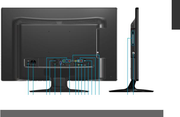
Rear view
ENGLISH
|
A B |
CD E F G H I J K LMNO |
P Q |
||
|
|
|
|
|
|
No. |
Name |
|
Description |
|
|
|
|
|
|
||
A |
AC Power Switch |
|
Use this switch to turn the main power on/off. |
||
|
|
|
|
|
|
B |
AC Power Input |
|
Connect to a AC power source. |
|
|
|
|
|
|||
C |
YPbPr Component Video |
Connect to the Component video (Y Pb Pr) output of video |
|||
Input |
|
devices. |
|
||
|
|
|
|||
|
|
|
|
||
D |
HDMI2 Input Terminal |
Connect to the HDMI digital audio/video output on digital |
|||
video devices. |
|
||||
|
|
|
|
||
E |
HDMI1 Input Terminal |
Connect to the HDMI digital audio/video output or DVI |
|||
digital video output on digital video devices. |
|||||
|
|
|
|||
|
|
|
|||
F |
VGA (PC Video Input) |
Connect to the RGB video (D-sub) output of PCs. |
|||
|
|
|
|
||
|
|
|
Connect to external equipment with scart socket. This scart |
||
G |
SCART Input |
|
input allows audio and CVBS/YC/RGB+CVBS. RGB, |
||
|
|
|
S-VIDEO from an external devise to be shown on your TV. |
||
|
|
|
|||
H |
AV Composite Video |
Connect to the Composite video (AV) output of video |
|||
Input |
|
devices. |
|
||
|
|
|
|||
|
|
|
Connect to the audio output of PCs. This jack is used for |
||
I |
PC/DVI Audio In |
|
PC Audio input, when the picture input is connected to |
||
|
|
|
VGA or DVI (via HDMI1 input) on the PC. |
||
|
|
|
|
|
|
ViewSonic |
17 |
VT2205LED/VT2405LED |
 Loading...