


For the operator / for the expert technician
Operating and Installation Manual
VRT 392f
Room thermostat with radio transmission |
VRT 392f |
GB


For the owner
Operating manual
VRT 392f
Room thermostat
Contents |
|
|
Equipment properties................................................ |
4 |
|
Application ............................................................................ |
4 |
|
Product specifications........................................................ |
4 |
|
1 |
Notes on the documentation......................... |
5 |
1.1 |
Storage of the documents .................................... |
5 |
1.2 |
Symbols used ........................................................... |
5 |
1.3 |
Validity of the instructions ................................... |
5 |
1.4 |
CE label...................................................................... |
5 |
2 |
Safety............................................................... |
5 |
3 |
Instructions for operation ............................. |
6 |
3.1 |
Intended use............................................................. |
6 |
3.2 |
Ambient conditions................................................. |
6 |
3.3 |
Care ............................................................................ |
6 |
3.4 |
Manufacturer's guarantee..................................... |
6 |
3.5 |
Recycling and disposal........................................... |
6 |
4 |
Operation ......................................................... |
7 |
4.1 |
Overview operating and display front................ |
7 |
4.2 |
Overview of the displays....................................... |
8 |
4.3 |
Operating concept .................................................. |
8 |
4.3.1 |
Show various screens ............................................ |
9 |
VRT 392f
4.3.2 |
Changing parameters............................................. |
9 |
4.3.3 |
Operation in the default display.......................... |
11 |
4.4 |
Changing the target room temperature........... |
12 |
4.5Operation level for the operator, operation
level for the expert technician............................ |
13 |
4.6Screens at the operation level for the
|
operator.................................................................... |
13 |
4.7 |
Editing screens (examples) ................................. |
15 |
4.7.1Entering time programmes
|
(example for heating)........................................... |
15 |
4.7.2 |
Programming holiday periods............................ |
16 |
4.7.3 |
Heating settings .................................................... |
16 |
4.7.4 |
Entering the parameters for hot water |
|
|
generation................................................................ |
17 |
4.7.5 |
Changing the name of the system |
|
|
components............................................................. |
17 |
5 |
Status and error messages ......................... |
18 |
Equipment properties
Equipment properties
Application
The VRT 392f is a programmable room temperature controller for the heating system. The VRT 392f also controls the hot water generation.
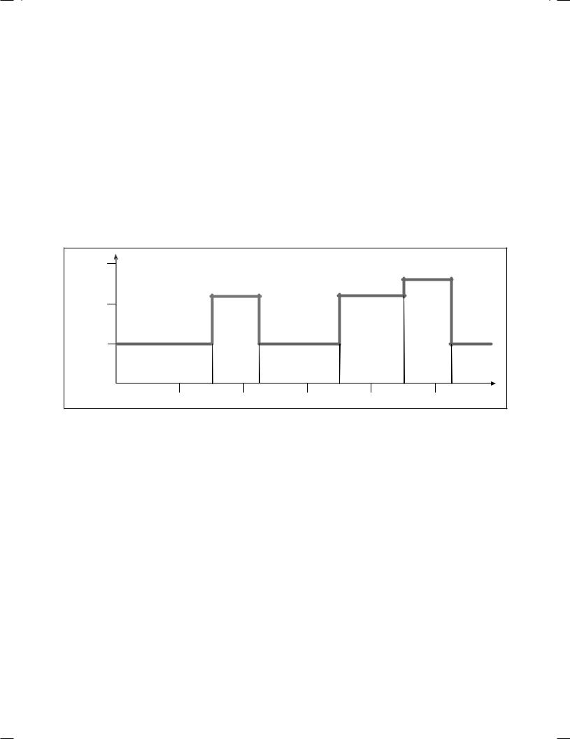
You can use the VRT 392f to specify various room target temperatures (programming) — for different times of the day and for different days of the week.
In automatic mode, the VRT 392f controls your heating in accordance with this input (see Fig. 0.1).
You can also use the VRT 392f to define daily heat-up times for hot water generation.
temperature |
25 ° |
|
|
|
|
|
|
|
|
|
|
|
|
|
|
Room |
20 |
° |
|
|
|
|
|
|
|
|
|
|
|
|
|
|
|
Set back temperature |
|
|
|
|
|
|
15 |
° |
|
|
|
|
|
|
|
|
Period 1 |
|
Period 2 |
Period 3 |
|
|
|
04:00 |
08:00 |
12:00 |
16:00 |
20:00 |
Time |
Fig. 0.1 Automatic heating operation: Example of setting the room target temperature for different times of the day
In addition, the VRT 392f can be used to control the following accessory components:
–Circulation pump for water heating in combination with a VR 40 multi-functional module
–Conventional hot water cylinder
–Vaillant layer type storage tank actoSTOR
The VRT 392f can be part of a new heating and hot water system or it can be incorporated into
existing heating systems. The appliance must have an eBUS interface.
eBUS is a standard communication method used for the exchange of data between heating technology components.
Product specifications
–eBUS interface
–Wireless communication with a Vaillant appliance
–Illuminated graphical display (display field)
–Operation via both dials in accordance with the principle "Turn and Click"
–The radio receiver unit can be mounted directly on the
operating panel of the appliance or separately on the wall
- The controller can be mounted separately on the wall
–Equipped for operation with the Vaillant diagnosis software vrDIALOG 810/2 and the Vaillant Internet Communication System vrnetDIALOG, i.e. remote diagnosis and remote adjustment
4 |
Operating manual VRT 392f 0020044239_01 |

Notes on the documentation 1 Safety 2
1Notes on the documentation
The following notes are intended to help you throughout the entire documentation. Further documents
apply in combination with this operating manual.
We accept no liability for any damage caused by failure to observe these instructions.
Other applicable documents
–Installation instructions for the Vaillant room thermostat VRT 392f (Part 2 of this document; for the expert technician)
–The operating and installation instructions for your heating system
–All instructions for the accessories
Glossary
An explanation of technical terms and important functions is provided in alphabetical order at the end of this document.
1.1Storage of the documents
Please store this operating manual and all related documents in such a way that they are available whenever required.
1.2Symbols used
Please observe the safety instructions in this manual for the installation of the appliance!
eDanger!Immediate risk of serious injury or death!
eDanger!Danger of death by electric shock!
HCaution!Danger of burning and scalding!
aCaution!Potentially dangerous situation for the product and environment!
hNoteUseful information and tips.
Symbol for a necessary task
1.3Validity of the instructions
These operating instructions apply exclusively for equipment with the following part numbers:
0020028510, 0020028511, 0020028512, 0020028513, 0020028514
4024074518083, 4024074518090, 4024074518106, 4024074518113, 4024074518328
The part number of your equipment can be obtained from your expert technician.
1.4CE label
The CE label confirms that the Vaillant Room Temperature Controller VRT 392f fulfils the fundamental requirements of the following relevant directives.
2Safety
The VRT 392f may only be installed by a certified expert technician. This person is also responsible for the proper installation and initial operation.
HCaution!Risk of being scalded by hot water!
When the target temperature is
above 60 °C, there is a risk of scalding at the hot water taps. Small children and elderly people can be at danger even at lower temperatures.
Risk to persons should be excluded through the selection of an appropriate target temperature (see Section 4.7.4).
Caution!
Risk of being scalded by hot water!
If your expert technician has activated the anti-legionella function for the hot water cylinder, the temperature of the hot water at the draw-off points may exceed 60 °C at specific times.
Find out from your expert technician whether the anti-legionella function has been activated and if so, on what day and at what time.
Operating manual VRT 392f 0020044239_01 |
5 |

3 Instructions for operation
3Instructions for operation
3.1Intended use
The VRT 392f is a state-of-the-art device which has been constructed in accordance with the standard safety regulations.
However, in the event of improper use or use not as intended, impairment of the equipment and other items can arise.
The VRT 392f serves the room temperature and timedependent control of a heating installation with or without hot water generation/circulation pump in conjunction with a Vaillant appliance and an eBUS interface.
Operation with the following accessories is permissible:
–Circulation pump for water heating in combination with a VR 40 multi-functional module
–Conventional hot water cylinder
–Vaillant layer type storage tank actoSTOR
Any other use or extended use is considered to be use other than intended. The manufacturer or supplier is not liable for any resulting damage. The owner alone bears any risk.
Intended use also includes observance of the Operating and Installation Manual as well as all other applicable documents.
3.2Ambient conditions
The controller and radio receiver unit may only be installed in dry rooms.
Please make sure:
–that the air in the room can circulate freely around the VRT 392f and the VRT 392f is not covered by furniture, curtains or other objects.
–that all the radiators in the room where the VRT 392f is fitted are fully on.
3.3Care
Clean the casing of the VRT 392f with a damp cloth. Do not use abrasive materials or cleaning agents that could damage the operator control elements, parts of the casing or display.
3.4Manufacturer's guarantee
Vaillant warranty
We only grant a Vaillant manufacturers warranty if
a suitably qualified engineer has installed the system in accordance with Vaillant instructions. The system owner will be granted a warranty in accordance with the Vaillant terms and conditions. All requests for work during the guarantee period must be made to
Vaillant Service Solutions (0870 6060 777).
Vaillant Service
To ensure regular servicing, it is strongly recommended that arrangements are made for a Maintenance Agreement. Please contact Vaillant Service Solutions (0870 6060 777) for further details.
3.5Recycling and disposal
Your VRT 392f and its packaging are primarily made of recyclable raw materials.
Appliance
The VRT 392f and its accessories must not be disposed of in the household waste. Make sure the old device and any existing accessories are disposed of properly.
Packaging
Please leave the disposal of the transport packaging to the qualified servicing company which installed the appliance.
Batteries
Batteries must not be disposed of in the household waste. Ensure that the batteries are disposed of properly.
6 |
Operating manual VRT 392f 0020044239_01 |
Operation 4
4Operation
hNoteHave your expert technician explain the operator input for the controller once the installation is complete. This will prevent the settings being changed unintentionally.
4.1Overview operating and display front
Th. 12.01.06 |
1 |
|
|
11:46 |
|
Auto |
19.0 °C |
|
VRT 392f |
3 |
2 |
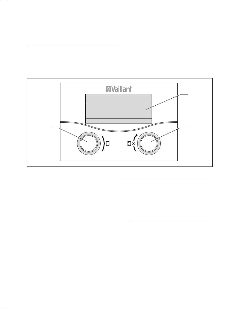
Fig. 4.1 Overview of operator control and display panel
Key
1Display
2 Operating element of the right-hand dial
3 Operating element of the left-hand dial
Fig. 4.1 shows the default display. The following information can be obtained from the default display:
–the type of operation (automatic, manual or off) of the heating circuit
–the current room temperature
The default display is described in detail in Section 4.3.3.
The functions of both dials are described in Section 4.3.
hNoteThe display is normally switched off to save power. This increases the service life of the batteries.
The display and lighting are activated as soon as you turn or click one of the dials. If the appliance is not used for more than one minute the basic display returns and switches off after approx. 10 minutes.
Note
When the dial is turned the values to be displayed must first be called up by the radio receiver unit. Until these values are obtained only dashes instead of values will be displayed (--). This generally takes up to two seconds. Depending on the ambient conditions, it may take up to 15 minutes until the current data are called up by the radio receiver unit and are subsequently displayed.
If dashes (--) are displayed continuously, consult your expert technician.
Operating manual VRT 392f 0020044239_01 |
7 |
4 Operation
4.2Overview of the displays
The display and input parameters (operating values) of the VRT 392f are shown on the various screens.
The screens are sub-divided into:
–Default display (Fig. 4.8)
–Basic display (Fig. 4.2)
–Display/input screens for certain parameters in the operator level
–Display/input screens for operating and system-specific parameters at the expert technician level
All the screens are divided into three areas.
Th. 12.01.06 |
|
|
1 |
11:46 |
|
|
|
HC1 |
21.0 °C |
Auto |
2 |
Hot water |
56.0 °C |
Auto |
|
> Change room temperature |
|
3 |
|
|
|
|
|
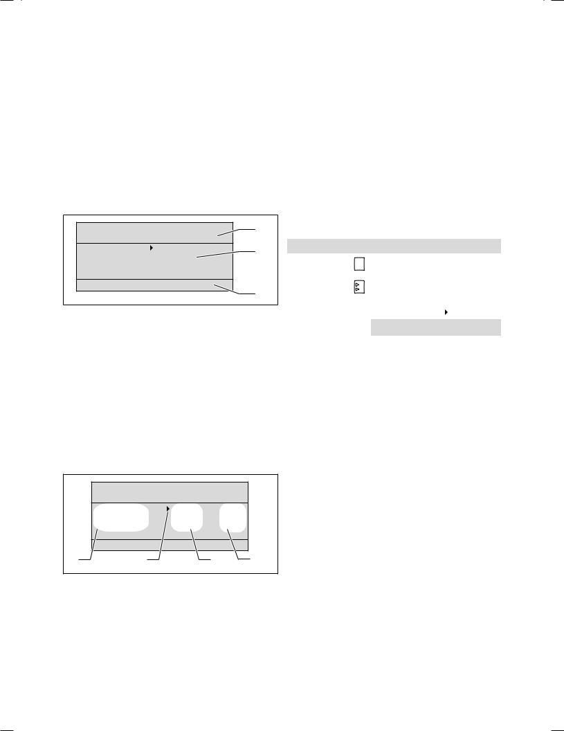
Fig. 4.2 Overview display (example basic display)
Key
1Area for basic data, title of the screen or status and error messages
2 Area for display and input of parameters
3 Area for display of explanations
The basic data are:
–Current day
–Date
–Time of the day
4.3Operating concept
The operator input in the default display is described in Section 4.3.3.
The operating concept described below applies to the basic display (Fig. 4.2) and to the various different display/input screens of the user level.
The two dials (Fig. 4.1 Items 2 and 3) function according to the Vaillant "Turn and Click" principle.
When turning (forwards or backwards) the adjusters locate in the next position with a detectable click. Each index step also moves the cursor one position forwards or backwards in the display.
By clicking (pressing) you can highlight or accept changes to a parameter.
|
|
|
Action |
Result |
|
|
|
|
|
Left-hand dial |
|
|
Turn |
Scroll to next screen |
|
|
|||
|
|
|
|
|
|
|
|
|
|
Right-hand dial |
Turn |
Scroll to an |
||
|
input field within |
|||
|
|
|
|
|
|
|
|
|
a screen (marked by |
|
|
|
|
cursor ) |
|
|
|
|
|
|
|
|
Changing a parameter |
|
|
|
|
|
|
|
|
|
Clicking |
Highlight for |
|
|
|
(pushing) |
changing |
|
|
|
|
|
|
|
|
Turn |
Change the |
|
|
|
|
parameter value |
|
|
|
|
|
|
|
|
Clicking |
Acceptance of |
|
|
|
(pushing) |
selected parameter |
|
|
|
|
value |
|
|
|
|
|
Table 4.1 Operating concept |
|
|||
The title of the screen appears instead of the basic data in the display/input screens for the specific parameters (see Fig. 4.12).
Th. 12.01.06 |
|
|
|
11:46 |
|
|
|
HC1 |
21.0 °C |
|
Auto |
Hot water |
56.0 °C |
|
Auto |
> Change room temperature |
|
|
|
1 |
2 |
3 |
4 |
Fig. 4.3 Area for display and input of parameters (example basic display)
Key
1Parameter name (only display)
2 The cursor  marks the jump to a modifiable value
3 Input field for parameter values; here: target set temperature 4 Input field for parameter values; here: Operating mode
8 |
Operating manual VRT 392f 0020044239_01 |

Operation 4
4.3.1Show various screens
By turning the left-hand dial you can page through the individual screens of the display like a book.
Example:
You are now located in the basic display. A description of how to navigate to the basic display is provided in Section 4.3.3.
Turn the left-hand dial clockwise by one notch.
4.3.2Changing parameters
Turn the right-hand dial to scroll through the parameters within the screen.
The position is indicated by the cursor  (see Fig. 4.5).
If a parameter (e.g. a date with day, month, year) consists of several elements, scroll from one element to the next by turning the right-hand dial.
The screen  1 appears in the display together with the basic data setting options.
|
|
|
|
|
|
Th. 12.01.06 |
|
|
|
|
|
|
|
|
11:46 |
|
|
|
|
|
|
|
|
HC1 |
21.0 °C |
Auto |
Th. 12.01.06 |
|
|
|
|
Hot water |
56.0 °C |
Auto |
|
11:46 |
|
|
|
|
|
|
|
|
HC1 |
|
|
|
22.0 °C |
Auto |
> Change room temperature |
|
|
|
|
|
|
|
|
|
|
|
Hot water |
|
|
|
56.0 °C |
Auto |
|
|
|
> Change room temperature |
|
|
Th. 12.01.06 |
|
|
|||
|
|
11:46 |
|
|
||||
|
|
|
|
|
|
|
|
|
|
|
|
|
|
|
HC1 |
21.0 °C |
Auto |
Basic data |
|
|
|
|
1 |
Hot water |
56.0 °C |
Auto |
Date |
|
|
21. 06. 06 |
|
> Change operating mode |
|
|
|
Day |
|
|
We |
|
|
|
|
|
|
|
|
|
|
|
|
||
Time |
|
|
12 : 00 o'clock |
|
|
|
||
Summer/Winter changeover |
Auto |
|
|
|
|
|||
> Select day |
|
|
|
|
Th. 12.01.06 |
|
|
|
|
|
|
|
11:46 |
|
|
||
|
|
|
|
|
|
|
|
|
|
|
|
|
|
|
HC1 |
21.0 °C |
Auto |
HC 1 |
|
|
|
|
2 |
Hot water |
56.0 °C |
Auto |
|
|
|
|
|
|
|
||
Time programme |
|
|
|
|
|
|
|
|
Mo |
|
|
|
|
|
> Change target hot water |
|
|
1 |
06 : 00 |
- |
10 : 40 |
21.5 °C |
|
|
|
|
2 |
: |
- |
: |
|
|
Fig. 4.5 Scroll to various different modifiable parameters |
||
3 |
: |
- |
: |
|
|
|||
|
|
|
|
|
||||
> Select day of week |
|
|
|
|
|
|
||
Fig. 4.4 Display of the various screens |
|
|
|
|
|
|||
Operating manual VRT 392f 0020044239_01 |
9 |

4 Operation
Click the right-hand dial.
The parameter value marked by the cursor  is inversely displayed.
|
|
|
|
|
|
|
|
|
|
|
|
|
|
|
|
|
|
|
|
|
|
|
|
|
|
|
|
|
|
|
|
|
|
|
|
|
|
|
|
|
|
|
|
|
|
|
|
|
|
|
|
|
|
|
|
Th. 12.01.06 |
|
|
|
|
|
|
|
||
|
11:46 |
|
|
|
|
|
|
|
|
|
|
|
|
|
|
|
|||||
|
HC1 |
21.0 |
°C |
Auto |
|
|||||
|
Hot water |
56.0 |
°C |
Auto |
|
|||||
|
|
|
|
|
|
|
|
|
||
|
> Change room temperature |
|
|
|
|
|
|
|
||
|
|
|
|
|
|
|
|
|
|
|
|
|
|
|
|
|
|
|
|
|
|
Fig. 4.6 Highlighting a parameter |
|
|
|
|
|
|
|
|||
Turn the right-hand dial to show the possible values.
Th. 12.01.06 11:46
HC1 |
21.0 |
°C |
Auto |
Hot water |
56.0 |
°C |
Auto |
|
|
|
|
> Change room temperature |
|
|
|
|
|
|
|
|
|
|
|
Th. 12.01.06 |
|
|
|
11:46 |
|
|
|
|
|
|
|
HC1 |
21.5 |
°C |
Auto |
Hot water |
56.0 |
°C |
Auto |
|
|
|
|
> Change room temperature |
|
|
|
|
|
|
|
|
|
|
|
Th. 12.01.06 |
|
|
|
11:46 |
|
|
|
|
|
|
|
HC1 |
22.0 |
°C |
Auto |
Hot water |
56.0 |
°C |
Auto |
|
|
|
|
> Change room temperature |
|
|
|
|
|
|
|
Fig. 4.7 Changing the values of a parameter
Click the right-hand dial.
The value displayed is confirmed and adopted for control purposes. The value is saved and is no longer highlighted.
10 |
Operating manual VRT 392f 0020044239_01 |
Changing parameters in the basic display
|
Parameter |
Meaning |
|
|
|
|
|
|
Room target |
The heating is controlled with |
|
|
temperature |
reference to the modified room target |
|
|
|
temperature for a specific period that |
|
|
|
depends on the operating mode |
|
|
|
selected, also see Section 4.4. |
|
|
|
|
|
|
Operating |
The control of the heating unit is |
|
(HC1) |
mode |
carried out in accordance with the |
|
Auto(matic) |
preset room set target temperature, |
||
|
|||
circuit |
|
the time programmes and other |
|
|
parameters such as e.g. night set back |
||
|
|
||
|
|
temp. |
|
Heating |
|
Some of these parameters are set by |
|
|
your expert technician. |
||
|
|
||
|
|
|
|
|
Operating |
The control of the heating unit |
|
|
mode |
depends upon the set room target |
|
|
Manual |
temperature. |
|
|
|
|
|
|
Operating |
The appliance is switched off. The |
|
|
mode |
room temperature is not displayed and |
|
|
OFF |
cannot be changed. |
|
|
|
Frost protection (room set target |
|
|
|
temperature = 5 °C) is guaranteed. |
|
|
|
|
|
|
Hot water |
The water heating is controlled with |
|
|
target set |
reference to the modified target hot |
|
|
temperature |
water value for a specific period that |
|
|
|
depends on the operating mode |
|
|
|
selected, also see Section 4.4. |
|
|
|
|
|
water |
Operating |
The hot water generation is controlled |
|
mode |
according to the target hot water and |
||
|
|||
|
Auto(matic) |
time programme settings. |
|
Hot |
|
|
|
Operating |
The hot water generation is controlled |
||
|
|||
|
mode |
with reference to the target hot water |
|
|
Manual |
setting. |
|
|
|
|
|
|
Operating |
The hot water is switched off. The |
|
|
mode |
target hot water temperature is not |
|
|
OFF |
displayed and cannot be changed. |
|
|
|
Frost protection is active. |
|
|
|
|
Table 4.2 Modifiable parameters in the basic display
Example: Change the room set target temperature of the heating circuit (HC1)
Initial condition: You are in the basic display
(see Fig. 4.2). A description of how to navigate to the basic display is provided in Section 4.3.3.
Turn the dial on the right until the cursor  appears in front of the target value (room target temperature) of the heating circuit (HC1).
Click the right-hand dial.
The input field for the target value is inversely displayed.
Turn the right-hand dial.
The value for the room temperature changes by 0.5 °C for each index turn of the dial.
Click the right-hand dial once the
required value for the room target temperature has been reached.
Operating manual VRT 392f 0020044239_01
Operation 4
The new value is applied. The display changes from inverse back to normal.
This new value applies to the control for a specific period, depending on the operating mode selected; also see Section 4.4.
4.3.3Operation in the default display
In the simplified basic display (Fig. 4.8) in the central area the operating mode for the heating circuit and the internal temperature are displayed.
The default display also provides you with the option of changing the two most important parameters of your heating system quickly and comfortably:
-By turning the left-hand dial you change the operating mode (automatic, manual, off).
-By turning the right-hand dial you can change between the actual room temperature and the set room temperature.
Th. 12.01.06 11:46
Auto |
19.0 °C |
|
|
|
VRT 392f |
Fig. 4.8 Default display (example)
You can navigate from the default display to the
next screen by clicking one or both dials (see Fig. 4.2).
If the controller is not operated for more than one minute, the display changes to the default display.
Changing the operating mode in the default display
Operating |
Meaning |
mode |
|
|
|
Auto(matic) |
The heating circuit is controlled with reference |
|
to the specified room target temperature, the |
|
time programme and other parameters, e.g. |
|
night set back temp. |
|
Some of these parameters are set by your |
|
expert technician. |
|
|
Manual |
The control of the appliance depends upon the |
|
set room temperature. |
|
|
OFF |
The heating circuit is switched off. The room |
|
temperature is not displayed and cannot be |
|
changed. |
|
Frost protection (room set target |
|
temperature = 5 °C) is guaranteed. |
|
|
Table 4.3Operating modes of the heating circuit
11
 Loading...