


For the installer
Instructions for installation and servicing
ecoTEC plus
Wall hung open vent condensing boiler
GB, IE

Contents
1 |
Introduction. . . . . . . . . . . . . . . . . . . . . . . . . . . |
3 |
1.1 |
Notes on the documentation. . . . . . . . . . . . . . . . |
3 |
1.1.1 |
Other instructions supplied with this appliance. . . |
3 |
1.1.3 |
Safety instructions and symbols. . . . . . . . . . . . . |
3 |
1.2 |
Validity of the manual. . . . . . . . . . . . . . . . . . . . . . |
4 |
1.3 |
ecoTEC plus boilers . . . . . . . . . . . . . . . . . . . . . . . . |
4 |
1.4 |
Intended use . . . . . . . . . . . . . . . . . . . . . . . . . . . . . . |
4 |
1.5 |
General information . . . . . . . . . . . . . . . . . . . . . . . |
4 |
1.5.1 |
Gas category. . . . . . . . . . . . . . . . . . . . . . . . . . . . . . |
4 |
1.5.2 |
Gas safety (installation and use) regulations. . |
4 |
1.5.3 |
Gas testing and certification . . . . . . . . . . . . . . . . |
4 |
1.5.4 |
Control of substances hazardous to health . . . |
5 |
1.5.5 |
Insulation pads . . . . . . . . . . . . . . . . . . . . . . . . . . . . |
5 |
1.5.6 |
Spare parts . . . . . . . . . . . . . . . . . . . . . . . . . . . . . . . |
5 |
1.5.7 |
Manual handling guidance . . . . . . . . . . . . . . . . . . |
5 |
1.5.8 |
Gas leak or fault. . . . . . . . . . . . . . . . . . . . . . . . . . . |
5 |
1.5.9 |
Clearances. . . . . . . . . . . . . . . . . . . . . . . . . . . . . . . . |
5 |
1.5.10 |
Sheet metal parts . . . . . . . . . . . . . . . . . . . . . . . . . |
5 |
1.5.11 |
Sealed components . . . . . . . . . . . . . . . . . . . . . . . . |
5 |
1.5.12 |
Electrical supply failure . . . . . . . . . . . . . . . . . . . . |
5 |
1.5.13 |
Protection against freezing . . . . . . . . . . . . . . . . . |
5 |
1.5.14 |
Boilers installed in a compartment or |
|
|
cupboard. . . . . . . . . . . . . . . . . . . . . . . . . . . . . . . . . . . |
5 |
1.5.15 |
Boiler casing . . . . . . . . . . . . . . . . . . . . . . . . . . . . . |
6 |
1.5.16 |
Condensate drain. . . . . . . . . . . . . . . . . . . . . . . . . . |
6 |
1.5.17 |
Pluming from flue terminal . . . . . . . . . . . . . . . . . |
6 |
1.5.18 |
Cleaning. . . . . . . . . . . . . . . . . . . . . . . . . . . . . . . . . . |
6 |
1.5.19 |
Maintenance and servicing . . . . . . . . . . . . . . . . . |
6 |
1.5.20 |
Technical data . . . . . . . . . . . . . . . . . . . . . . . . . . . . |
6 |
1.6 |
Statutory requirements . . . . . . . . . . . . . . . . . . . . |
6 |
1.7 |
Regulations, rules and guidelines. . . . . . . . . . . . |
6 |
1.8 |
CE label . . . . . . . . . . . . . . . . . . . . . . . . . . . . . . . . . . |
7 |
1.9 |
Benchmark . . . . . . . . . . . . . . . . . . . . . . . . . . . . . . . |
7 |
1.10 |
Gas council numbers . . . . . . . . . . . . . . . . . . . . . . . |
7 |
2 |
Boiler specifications . . . . . . . . . . . . . . . . . . . . |
8 |
2.1 |
Technical data . . . . . . . . . . . . . . . . . . . . . . . . . . . . |
8 |
2.1.2 |
Dimensions . . . . . . . . . . . . . . . . . . . . . . . . . . . . . . . |
9 |
2.1.3 |
Installation. . . . . . . . . . . . . . . . . . . . . . . . . . . . . . . . |
9 |
3 |
General requirements. . . . . . . . . . . . . . . . . . . . . |
10 |
3.1 |
Preliminary remarks . . . . . . . . . . . . . . . . . . . . . . . . . . . |
10 |
3.2 |
Related documents . . . . . . . . . . . . . . . . . . . . . . . . |
10 |
3.3 |
Installation site. . . . . . . . . . . . . . . . . . . . . . . . . . . . |
10 |
3.4 |
Gas supply . . . . . . . . . . . . . . . . . . . . . . . . . . . . . . . . |
11 |
3.5 |
Flue options . . . . . . . . . . . . . . . . . . . . . . . . . . . . . . |
11 |
3.5.1 |
Flue termination. . . . . . . . . . . . . . . . . . . . . . . . . . . |
12 |
3.5.2 |
Internal flue installation . . . . . . . . . . . . . . . . . . . . |
13 |
3.6 |
Air supply . . . . . . . . . . . . . . . . . . . . . . . . . . . . . . . . |
13 |
3.7 |
Cupboard or compartment ventilation . . . . . . . |
13 |
3.8 |
Domestic hot water cylinder . . . . . . . . . . . . . . . . |
13 |
3.8.1 |
Unvented hot water cylinder . . . . . . . . . . . . . . . . |
13 |
3.9 |
Condensate drain. . . . . . . . . . . . . . . . . . . . . . . . . . |
13 |
3.10 |
Heating system controls. . . . . . . . . . . . . . . . . . . . |
13 |
3.11 |
Draining tap . . . . . . . . . . . . . . . . . . . . . . . . . . . . . . |
13 |
3.12 |
Safety valve . . . . . . . . . . . . . . . . . . . . . . . . . . . . . . |
13 |
3.13 |
Bypass . . . . . . . . . . . . . . . . . . . . . . . . . . . . . . . . . . . |
13 |
3.14 |
Pump specification . . . . . . . . . . . . . . . . . . . . . . . . |
13 |
3.15 |
Cleanser and inhibitor. . . . . . . . . . . . . . . . . . . . . . |
14 |
3.16 Water pressure loss. . . . . . . . . . . . . . . . . . . . . . . . 15 3.17 Open vented heating system. . . . . . . . . . . . . . . . 16 3.18 Sealed water systems . . . . . . . . . . . . . . . . . . . . . . 16 3.18.1 Safety valve . . . . . . . . . . . . . . . . . . . . . . . . . . . . . . 16 3.18.2 Expansion vessel . . . . . . . . . . . . . . . . . . . . . . . . . . 16 3.18.3 Pressure gauge . . . . . . . . . . . . . . . . . . . . . . . . . . . 16 3.18.4 Water make up . . . . . . . . . . . . . . . . . . . . . . . . . . . . 16 3.18.5 Filling a sealed water system . . . . . . . . . . . . . . . 17
4 |
Boiler installation sequence. . . . . . . . . . . . . . |
18 |
4.1 |
Boiler location . . . . . . . . . . . . . . . . . . . . . . . . . . . . |
18 |
4.1.1 |
Sheet metal parts . . . . . . . . . . . . . . . . . . . . . . . . . |
18 |
4.1.2 |
Clearances. . . . . . . . . . . . . . . . . . . . . . . . . . . . . . . . |
18 |
4.1.3 |
Timber frame buildings. . . . . . . . . . . . . . . . . . . . . |
18 |
4.1.4 |
Contents included with delivery . . . . . . . . . . . . . |
18 |
4.2 |
Flue exit . . . . . . . . . . . . . . . . . . . . . . . . . . . . . . . . . . |
19 |
4.2.1 |
Other flue options . . . . . . . . . . . . . . . . . . . . . . . . . |
19 |
4.3 |
Fitting the boiler hanging bracket . . . . . . . . . . . |
19 |
4.3.1 |
Boiler fixing. . . . . . . . . . . . . . . . . . . . . . . . . . . . . . . |
19 |
4.3.2 |
Removing the front casing. . . . . . . . . . . . . . . . . . |
19 |
4.3.3 |
Gas connection. . . . . . . . . . . . . . . . . . . . . . . . . . . . |
19 |
4.3.4 |
Water connections. . . . . . . . . . . . . . . . . . . . . . . . . |
20 |
4.3.5 |
Condensate trap and siphonic drain |
|
|
connection . . . . . . . . . . . . . . . . . . . . . . . . . . . . . . . . . |
20 |
4.3.6 |
Installing the flue system . . . . . . . . . . . . . . . . . . . |
21 |
4.4 |
Electrical connections. . . . . . . . . . . . . . . . . . . . . . |
21 |
4.4.1 |
Connection to the main supply . . . . . . . . . . . . . . |
21 |
4.4.2 |
Wiring system. . . . . . . . . . . . . . . . . . . . . . . . . . . . . |
22 |
4.4.3 |
Electrical board layout . . . . . . . . . . . . . . . . . . . . . |
23 |
4.4.4 |
Controls . . . . . . . . . . . . . . . . . . . . . . . . . . . . . . . . . . |
25 |
4.4.5 |
External electrical controls . . . . . . . . . . . . . . . . . |
25 |
4.4.6 |
Connection details for external switches |
|
|
and boiler terminal strip. . . . . . . . . . . . . . . . . . . . |
26 |
4.4.7 |
Vaillant optional plug in timer |
|
|
accessories . . . . . . . . . . . . . . . . . . . . . . . . . . . . . . . |
26 |
4.4.8 |
Connection details using the VR 65 |
|
|
and VR 61 control centre . . . . . . . . . . . . . . . . . . . |
26 |
5 |
Commissioning (Part I). . . . . . . . . . . . . . . . . . |
27 |
5.1 |
Preliminaries - all systems . . . . . . . . . . . . . . . . . . |
27 |
5.1.1 |
Gas supply . . . . . . . . . . . . . . . . . . . . . . . . . . . . . . . . |
27 |
5.1.2 |
Gas pressure statement - Natural gas. . . . . . . . |
28 |
5.1.3 |
Initial Lighting. . . . . . . . . . . . . . . . . . . . . . . . . . . . . |
28 |
5.1.4 |
Ignition problems . . . . . . . . . . . . . . . . . . . . . . . . . . |
29 |
5.1.5 |
Flue problems . . . . . . . . . . . . . . . . . . . . . . . . . . . . . |
29 |
5.1.6 |
Testing - gas . . . . . . . . . . . . . . . . . . . . . . . . . . . . . . |
29 |
6 |
Natural gas to LPG conversion . . . . . . . . . . . |
30 |
7 |
Functional checks commissioning (part II). . |
31 |
7.1 |
Functional checks . . . . . . . . . . . . . . . . . . . . . . . . . |
31 |
7.2 |
Heating. . . . . . . . . . . . . . . . . . . . . . . . . . . . . . . . . . . |
31 |
7.3Domestic hot water (If optional VR65, uniSTOR cylinder and Vaillant control
|
are installed). . . . . . . . . . . . . . . . . . . . . . . . . . . . . . |
31 |
7.4 |
Pump exercise programme . . . . . . . . . . . . . . . . . |
31 |
7.5 |
Final flush of the heating system (hot) . . . . . . . |
31 |
7.6 |
Handing over to the user . . . . . . . . . . . . . . . . . . . |
32 |
2 |
Instructions for installation and servicing ecoTEC plus 0020020828_07 |

Contents
Introduction 1
8 Inspection and maintenance . . . . . . . . . . . . . 32
8.1 Inspection and maintenance intervals. . . . . . . . 32
8.1.1General inspection and maintenance
instructions . . . . . . . . . . . . . . . . . . . . . . . . . . . . . . . 33 8.1.2 Maintenance . . . . . . . . . . . . . . . . . . . . . . . . . . . . . . 33 8.1.3 Checking the CO/CO2 ratio . . . . . . . . . . . . . . . . . 33 8.1.4 General. . . . . . . . . . . . . . . . . . . . . . . . . . . . . . . . . . . 35 8.1.5 Spark electrode . . . . . . . . . . . . . . . . . . . . . . . . . . . 36 8.1.6 Removing the burner . . . . . . . . . . . . . . . . . . . . . . 36 8.1.7 Combustion chamber and heat exchanger . . . . 37 8.1.8 Condensate drain. . . . . . . . . . . . . . . . . . . . . . . . . . 37 8.1.9 Inner casing panel seal check . . . . . . . . . . . . . . . 37 8.1.10 Checking the expansion vessel (If fitted). . . . . . 37 8.1.11 Re commissioning the boiler . . . . . . . . . . . . . . . . 38 8.1.12 Test operation . . . . . . . . . . . . . . . . . . . . . . . . . . . . 38
9 |
Combustion analysis. . . . . . . . . . . . . . . . . . . . |
38 |
9.1 |
Check CO2 content. . . . . . . . . . . . . . . . . . . . . . . . . |
38 |
10 |
Troubleshooting. . . . . . . . . . . . . . . . . . . . . . . . |
40 |
10.1 |
Logical fault finding procedure. . . . . . . . . . . . . . |
40 |
10.1.1 |
Status codes . . . . . . . . . . . . . . . . . . . . . . . . . . . . . . |
40 |
10.1.2 |
Diagnostic codes . . . . . . . . . . . . . . . . . . . . . . . . . . |
40 |
10.1.3 |
Fault codes . . . . . . . . . . . . . . . . . . . . . . . . . . . . . . . |
43 |
10.1.4 |
Fault memory . . . . . . . . . . . . . . . . . . . . . . . . . . . . . |
43 |
10.2 |
Test programs . . . . . . . . . . . . . . . . . . . . . . . . . . . . |
44 |
10.3 |
Resetting parameter to factory settings. . . . . . |
44 |
11 Parts replacement . . . . . . . . . . . . . . . . . . . . . 45
11.1 Safety instructions . . . . . . . . . . . . . . . . . . . . . . . . 45 11.2 Replacing the burner. . . . . . . . . . . . . . . . . . . . . . . 45 11.3 Replacing the gas valve . . . . . . . . . . . . . . . . . . . . 45 11.4 Replacing the fan. . . . . . . . . . . . . . . . . . . . . . . . . . 45 11.5 Replacing the heat exchanger. . . . . . . . . . . . . . . 45
11.6Replacing the condense trap and
siphonic drain . . . . . . . . . . . . . . . . . . . . . . . . . . . . . 46 11.7 Replacing electronics and display . . . . . . . . . . . 46
12 Recycling and disposal . . . . . . . . . . . . . . . . . . 47
12.1 Appliance. . . . . . . . . . . . . . . . . . . . . . . . . . . . . . . . . 47 12.2 Packaging . . . . . . . . . . . . . . . . . . . . . . . . . . . . . . . . 47
13 Factory guarantee and Vaillant service . . . . 47
13.1 Factory guarantee . . . . . . . . . . . . . . . . . . . . . . . . . 47 13.2 Vaillant service. . . . . . . . . . . . . . . . . . . . . . . . . . . . 47
14 Appendix . . . . . . . . . . . . . . . . . . . . . . . . . . . . . 48
1Introduction
1.1Notes on the documentation.
To ensure clarity of information in instructions a new European standard of advice and symbols is being introduced. To ensure compliance with this new standard the following details are included.The following information is intended to help you through-out the boilers entire instruction pack. We assume no liability for any damage caused by non-observance of these instructions.
1.1.1Other instructions supplied with this appliance.
For the owner: |
|
Instructions for use |
no. 0020020829 |
Short operating instructions |
no. 838404 |
Warranty card with return envelope |
no. 802922 |
For the installer/service engineer: |
|
Flue installation instructions |
no. 834449 |
The instructions for any accessories and controllers used also apply.
The Benchmark gas boiler commissioning checklist (in this manual) should be completed by the installer and/or the commissioning engineer.
If, after reading these instructions, you have any questions on the operation of the boiler, please contact either your installer or Vaillant Technical Department.
1.1.2Retention of documents
Please retain this literature and all related documents so that they are available whenever they are required. If you move please pass on the documents to the buyer.
1.1.3Safety instructions and symbols
Please observe the safety instructions in this literature for the operation of the appliance.
d Danger!Immediate risk of serious injury or death.
eDanger!
Risk of death from electric shock!
HDanger!
Risk of burns or scalding!
a Caution!Potentially dangerous situations for the product and environment.
h Note!Useful information and instructions.
•Symbol for a necessary task
Instructions for installation and servicing ecoTEC plus 0020020828_07 |
3 |

1 Introduction
h Note!Installation and adjustment of the boiler as well as service, maintenance and repair may only be carried out by a competent person approved at the time by the Health and Safety executive and in accordance with the gas safety (installation and use) regulations 1998.
1.2Validity of the manual
This installation manual applies exclusively to units with the following part numbers:
–0010002460
–0010002461
–0010002724
–0010002725
The part number of the unit can be obtained from the identification plate.
1.3ecoTEC plus boilers
The ecoTEC plus boilers are designed to provide central heating from a fully pumped open-vented or sealed water system. The central heating water temperature can be adjusted on the boiler. The domestic hot water can only be adjusted on the boiler if it is installed with a Vaillant uniSTOR unvented cylinder and relevant controls. Once the controls are set the boiler operates automatically.
A frost protection programme is also included.
Please read these instructions and follow them carefully for the correct and economical use of your boiler. These instructions are applicable to the following ecoTEC plus boilers, available in Natural Gas. All ecoTEC plus boilers can be converted to LPG.
Appliance |
Maximum output |
|
|
ecoTEC plus 415 |
15 kW |
|
|
ecoTEC plus 418 |
18 kW |
|
|
ecoTEC plus 428 |
28 kW |
|
|
ecoTEC plus 438 |
38 kW |
|
|
1.4Intended use
The boiler has been designed for use with a open-vented central heating system, and comes fully tested and assembled. The boiler is easily mounted on any internal wall and can be installed with either a horizontal or vertical RSF (room sealed fan assisted) flue. The boiler uses a standard flue system (100 mm or 125 mm outside diameter). Flue extensions and additional bends and elbows are available for the flue system to increase the flexibility. If desired, an inhibitor may be used in the system. Guidance on the use of inhibitors is contained in these instructions. The boiler has a built in diagnostic system which indicates the operational status of the boiler. This feature provides key information to aid commissioning and fault finding. The data badge is fitted to
the combustion chamber cover of the boiler. See text of General Requirements for installation requirements or notes.
The Vaillant ecoTEC plus boiler is a state-of-the-art appliance which has been constructed in accordance with recognised safety regulations. Nevertheless, danger to the life and limb of the user or third parties can still occur or the appliance or other material assets be impaired in the event of improper use.
The unit is not intended for use by persons (including children) with reduced physical, sensory or mental capabilities, or lack of experience and/or knowledge, unless they have been given supervision or instruction concerning use of the unit by a person responsible for their safety.
Children must be watched to ensure that they do not play with the unit.
The appliances are designed for central heating systems. Any other use or extended use is considered to be use other than intended. The user alone bears the risk. The manufacturer/ supplier is not liable for any resulting damage. Intended use includes the observance of the operating and installation manual and the adherence to the inspection and maintenance conditions.
aCaution!
Any incorrect use is forbidden. The appliances must be installed by a competent person approved at the time by the Health and Safety Executive, who is responsible for adhering to the existing regulations, rules and guidelines.
1.5General information
Thank you for choosing a Vaillant boiler. The information given in this booklet will enable you to obtain the best performance from this boiler.
1.5.1Gas category
The boiler is supplied factory set for use on Natural Gas (G20). The ecoTEC plus boilers can be field adjusted for use on LPG (propane G31), see section 6 for instructions or contact Vaillant Service, 0870 6060 777.
1.5.2Gas safety (installation and use) regulations
In your own interests and that of safety, it is the Law that ALL gas appliances are installed by a competent person approved at the time by the Health and Safety Executive in accordance with the current issue of the above regulations.
1.5.3Gas testing and certification
The boiler is tested and certificated for safety and performance. It is, therefore, important that no alteration is made to the boiler.
4 |
Instructions for installation and servicing ecoTEC plus 0020020828_07 |

Introduction 1
1.5.4Control of substances hazardous to health
Under Section 6 of The Health and Safety at Work Act 1974, we are required to provide information on substances hazardous to health. The adhesives and sealants used in this appliance are cured and give no known hazard in this state.
1.5.5Insulation pads
These can cause irritation to skin, eyes and the respiratory tract. If you have a history of skin complaint you may be susceptible to irritation. High dust levels are usual only if the material is broken. Normal handling should not cause discomfort, but follow normal good hygiene and wash your hands before eating, drinking or going to the lavatory. If you do suffer irritation to the eyes or severe irritation to the skin seek medical attention.
1.5.6Spare parts
Only original Vaillant spare parts may be used.
1.5.7Manual handling guidance
During the appliance installation (and any subsequent replacement of the heat exchanger) it will be necessary to employ caution. All installers and operatives involved from unloading the appliance until it is fully mounted on the wall in its final installed location must exercise full duty of care for themselves and others with regard to safe lifting and handling of this appliance. Operatives should employ assistance whilst lifting the appliance or components. In certain situations it may be required to use a mechanical handling aid. Take care to avoid trip hazards, slippery or wet surfaces.
aCaution!
With regards to the Manual Handling Operations, 1992 Regulations, the following lift operation exceeds the recommended weight for a one man lift.
Employers and installers should refer to the HSE web site for full advice and manual Handling assessment charts (MAC) tool.
dDanger!
Smell of gas. Risk of poisoning and explosion due to a malfunction.
1.5.8Gas leak or fault
If you smell gas or suspect a gas leak:
•Do not switch lights on or off.
•Do not use any other electrical switches.
•Do not use a telephone in the hazardous area.
•Do not use naked flames, such as matches or cigarette lighters.
•Do not smoke.
•Turn off the gas supply at the gas meter.
•Open the windows and doors.
•Warn other residents.
•Get out of the house.
•Consult your gas supplier, service agent or other competent person approved at the time by the Health and Safety Executive.
Telephone the National emergency number 0800 111 99
1.5.9Clearances
If fixtures are positioned close to the boiler, space must be left as shown in fig 4.1. Enough space must also be left in front of the boiler to allow for servicing.
1.5.10 Sheet metal parts
This boiler contains metal parts (components) and care should be taken when handling and cleaning, with particular regard to edges.
1.5.11Sealed components
Under no circumstances must the User interfere with any sealed component as this could result in a potentially dangerous situation arising.
eDanger!
This boiler must be earthed.
1.5.12 Electrical supply failure
The boiler will not work without an electrical supply. Normal operation of the boiler should resume when the electrical supply is restored. Reset any external controls to resume normal operation of the central heating. If the boiler does not resume normal operation. (The burner fails to ignite after five attempts). The overheat thermostat may have operated. Automatic ignition can only take place after you manually reset the fault, refer to section 5.1.3. to reset.
1.5.13 Protection against freezing
The boiler has a built in frost protection programme as long as the electricity and gas are left switched on. This device operates the burner and system pump when the temperature inside the boiler falls to 3°C. Any other exposed areas of the system should be protected by a separate frost thermostat. If the mains electricity and gas are to be turned off for any long periods during severe weather, it is recommended that the whole system, including the boiler, should be drained to avoid the risk of freezing. Make sure that, if fitted, the immersion heater in the cylinder is switched off. If you have a sealed water system contact your installation/ servicing company as draining, refilling and pressurising MUST be carried out by a competent person approved at the time by the Health and Safety Executive.
As a safety feature the boiler will stop working if the condensate drain becomes blocked. During freezing conditions this may be due to the forming of ice in the condense drain external to the house. Release an ice blockage by the use of warm cloths on the pipe. The boiler should then restart. Contact your installation/ servicing company if the fault persists.
Instructions for installation and servicing ecoTEC plus 0020020828_07 |
5 |

1 Introduction
1.5.14Boilers installed in a compartment or cupboard
If the boiler is fitted into a compartment or cupboard it does not require ventilation openings.
Do not use the compartment or cupboard for storage.
1.5.15Boiler casing
Do not remove or adjust the casing in any way, as incor- rect-fitting may result in incorrect operation or failure to operate at all.
1.5.16 Condensate drain
The condensate drain must not be modified or blocked.
1.5.17 Pluming from flue terminal
All condensing boilers produce a plume of water vapour from the flue terminal. This is due to the high efficiency and hence low flue gas temperature. This may increase in wet, damp weather but this is completely normal and indicates that the boiler is operating correctly.
1.5.18 Cleaning
This appliance contains metal parts and care should be taken when handling and cleaning with particular regard to edges. The boiler casing can be cleaned using a mild liquid detergent with a damp cloth, then a dry cloth to polish. Do not use any form of abrasive or solvent cleaner as you may damage the paint work.
1.5.19 Maintenance and servicing
For the continued efficient and safe operation of the boiler it is recommended that it is checked and serviced at regular intervals. The frequency of servicing will depend upon the installation conditions and usage, but in general, once a year should be enough.
If this appliance is installed in a rented property there is a duty of care imposed on the owner of the property by the current issue of the Gas Safety (Installation and Use) Regulations, Section 35. Servicing/maintenance should be carried out by a competent person approved at the time by the Health and Safety Executive in accordance with the rules in force in the countries of destination.
Please be advised that on completion of commissioning and servicing you should complete the Benchmark gas boiler commissioning checklist.
All competent persons approved at the time by the Health and Safety Executive carry a ID card, and have a registration number. Both should be recorded there.
1.5.20 Technical data
All dimensions are given in millimetres (except as noted). The data label is positioned on the combustion chamber cover. The Seasonal Efficiency Domestic Boilers UK (SEDBUK) is: All ecoTEC plus boilers : Class ‘A’. The value is used in the UK Government’s Standard Assessment Procedure (SAP) for energy rating of dwellings. The test data from which it has been calculated has been certified by B.S.I.
1.6Statutory requirements
The appliance is suitable only for installation in GB and IE and should be installed in accordance with the rules in force. In GB the installation of the boiler must be carried out by a competent person as described in the following regulations:
-The manufacturer’s instructions supplied
-The Gas Safety (Installation and Use) Regulations
-The appropriate Buildings Regulations either
-The Building Regulations
-The Building Regulations (Scotland)
-The Building Regulations (Northern Ireland)
-The Water Fittings Regulations or Water bye laws in Scotland
-The Health and Safety at Work Act, Control of Substances Hazardous to Health (COSHH)
-The Current I.E.E. Wiring Regulations
Where no specific instructions are given, reference should be made to the relevant British Standard Code of Practice. In IE, the installation must be carried out by a competent person and installed in accordance with the current edition of I.S.813 “Domestic Gas Installations”, the current Building Regulations and reference should be made to the current ETCI rules for Electrical Installation.
In GB the following Codes of Practice apply:
BS 4814, |
BS 6891 |
BS 6798 |
BS 6700 |
BS 5440 Part 1 and 2 |
BS 7074 Part 1 and 2 |
BS 5546 Part 1 |
BS 7593 |
BS 5449 |
BS 7671 |
In IE: |
|
I.S.813 |
BS 5546 |
BS 7074 |
BS 5449 |
BS 7593 |
|
Manufacturer’s instructions must not be taken as overriding statutory requirements.
hNote!
For further information, see the current issue of the Building Regulations, approved document L1 (in the UK) and the current issue of the following:
•Central heating system specification (CheSS)
•Controls for domestic central heating system and hot water (BRECSU).
Certification
This boiler certificated to the current issue of EN 483 for performance and safety. It is important that no alteration is made to the boiler, without permission, in writing, from Vaillant. Any alteration that is not approved by Vaillant, could invalidate the warranty and could also infringe the current issue of the Statutory Requirements.
6 |
Instructions for installation and servicing ecoTEC plus 0020020828_07 |
1.7Regulations, rules and guidelines.
This boiler meets the requirements of Statutory Instrument, No. 3083 The Boiler (Efficiency) Regulations, and therefore is deemed to meet the requirements of Directive 92/42/EEC on the efficiency requirements for new hot water boilers fired with liquid or gaseous fuels. Type test for purposes of Regulation 5 certified by: Notified body 0087. Product/production certified by: Notified body 0086.
1.8CE label
The CE label on this appliance shows compliance with:
-Directive 90/396/EEC on the approximation of the laws of the Member States relating to appliances burning gaseous fuels.
-Directive 73/23/EEC on the harmonisation of the Laws of the Member States relating to electrical equipment designed for use within certain voltage limits.
-Directive 89/336/EEC on the approximation of the Laws of the Member States relating to electromagnetic compatibility.
-Directive 92/42/EEC on the efficiency requirements.
1.9Benchmark
h Note!Vaillant Ltd. support the Benchmark initiative
At the rear of the installation manual, you will find a Benchmark gas boiler commissioning checklist. It is very important that this is completed correctly at the time of installation, commissioning and hand over to the user.
1.10Gas council numbers
Appliance |
Gas council numbers |
|
|
ecoTEC plus 415 |
41 - 044 - 53 |
|
|
ecoTEC plus 418 |
41 - 044 - 54 |
|
|
ecoTEC plus 428 |
41 - 044 - 55 |
|
|
ecoTEC plus 438 |
41 - 044 - 57 |
|
|
Instructions for installation and servicing ecoTEC plus 0020020828_07
Introduction 1
7

2 Boiler specifications
2Boiler specifications
2.1Technical data
Description |
ecoTEC plus 415 |
ecoTEC plus 418 |
ecoTEC plus 428 |
ecoTEC plus 438 |
Unit |
|
|
|
|
|
|
|
|
Maximum CH heat input (net) |
15.3 |
18.9 |
28.6 |
38.4 |
kW |
|
|
|
|
|
|
|
|
CH heat output (80/60 °C) |
5.0 - 15.0 |
5.0 - 18.6 |
5.3 - 28.2 |
6.3 - 38.0 |
kW |
|
|
|
|
|
|
|
|
CH heat output (50/30 °C) |
5.3 - 16.2 |
5.3 - 20.0 |
5.7 - 30.6 |
6.8 - 41.0 |
kW |
|
|
|
|
|
|
|
|
SEDBUK Band |
A |
A |
A |
A |
|
|
|
|
|
|
|
|
|
SAP Seasonal Efficiency |
90.5 |
90.4 |
90.6 |
90.8 |
% |
|
|
|
|
|
|
|
|
NOx Class |
5 |
5 |
5 |
5 |
|
|
|
|
|
|
|
|
|
lP rating |
IPX4D |
IPX4D |
IPX4D |
IPX4D |
|
|
|
|
|
|
|
|
|
Inlet gas working pressure required |
20 |
20 |
20 |
20 |
mbar |
|
(natural gas) |
||||||
|
|
|
|
|
||
|
|
|
|
|
|
|
Gas supply (G20) Gross CV (s.t.) |
37.8 |
37.8 |
37.8 |
37.8 |
MJ/m3 |
|
|
|
|
|
|
|
|
Maximum gas rate |
1.61 |
2.0 |
3.02 |
4.06 |
M3/h |
|
|
|
|
|
|
|
|
Minimum gas rate |
0.53 |
0.53 |
0.56 |
0.71 |
M3/h |
|
|
|
|
|
|
|
|
Burner % CO2 (Case on) |
9.3 + 0.2 - 0.5 |
9.3 + 0.2 - 0.5 |
9.3 + 0.2 - 0.5 |
9.0 + 0.2 - 0.5 |
% |
|
|
|
|
|
|
|
|
Gas connection (compression) |
15 |
15 |
15 |
15 |
mm |
|
|
|
|
|
|
|
|
Water connections (compression) |
22 |
22 |
22 |
22 |
mm |
|
|
|
|
|
|
|
|
Condensate drain (internal diameter) |
19 min. |
19 min. |
19 min. |
19 min. |
mm |
|
|
|
|
|
|
|
|
Main PCB |
2 |
2 |
2 |
2 |
A |
|
|
|
|
|
|
|
|
Minimum flow rate of water |
10.8 |
12.9 |
20.3 |
27.2 |
L/min. |
|
through the boiler |
||||||
|
|
|
|
|
||
|
|
|
|
|
|
|
Weight |
31 |
31 |
33 |
33 |
kg |
|
|
|
|
|
|
|
|
Electrical supply |
230/~50 |
230/~50 |
230/~50 |
230/~50 |
V~/HZ |
|
|
|
|
|
|
|
|
External fuse |
3 |
3 |
3 |
3 |
A |
|
|
|
|
|
|
|
|
Power input |
60 |
60 |
60 |
60 |
W |
|
|
|
|
|
|
|
|
Flue categories |
C13, C33, C43, C53 |
C13, C33, C43, C53 |
C13, C33, C43, C53 |
C13, C33, C43, C53 |
|
|
|
|
|
|
|
|
|
Case height |
600 |
600 |
600 |
600 |
mm |
|
|
|
|
|
|
|
|
Case width |
375 |
375 |
375 |
375 |
mm |
|
|
|
|
|
|
|
|
Case depth |
340 |
340 |
340 |
340 |
mm |
|
|
|
|
|
|
|
|
8 |
|
Instructions for installation and servicing ecoTEC plus 0020020828_07 |
||||

Boiler specifications 2
2.1.2 |
Dimensions |
|
|
|
|
|
5 |
1 |
161 |
|
|
|
|
|
|
|
113 |
53 |
160 |
|
|
||
|
|
|
|
2 |
|
|
|
|
|
|
4 |
|
610 |
|
|
|
|
30 |
|
3 |
|
133 |
7 |
|
56 |
||
|
|
||
|
|
|
|
|
|
375 |
|
|
26 |
|
6 |
|
48 |
|
|
|
|
|
|
|
33 |
|
|
|
|
|
8 |
|
|
|
176 |
|
|
|
340 |
Fig. 2.1 Dimensions in mm
2.1.3 |
Installation |
Fig. 2.2 Function elements of boiler
1 Flue pipe connection
2 Fan
3 Gas valve
4 Electronics box
5 Burner module
6 Ignition electrode
7 Condense trap
1 Heating return pipe Ø 22
2 Heating flow pipe Ø 22
3 Gas connection Ø 15
4 Hanging bracket
5 Flue hole - flue system 303 933
6 Flue pipe connection
7 Condensate drain outlet connection (Ø 21)
8 Outside wall face
Instructions for installation and servicing ecoTEC plus 0020020828_07 |
9 |

3 General requirements
3General requirements
3.1Preliminary remarks
This appliance must only be installed and commissioned by a suitably competent person. Please check with your installer that he is able to carryout all the necessary works including official notification of the works to the relevant body upon completion.
3.2Related documents
The installation of the appliance and any associated hot water system must be in accordance with (but not limited to) the following; COSHH regulations, Gas Safety (Installation and Use) Regulations 1998, Health and Safety Document No. 635 (The Electricity at Work Regulations 1989), BS7671 (IEE Wiring Regulations) and the Water Supply (Water Fitting) Regulations 1999, or The Water Bylaws 2000 (Scotland). It should also be in accordance with the relevant requirements of the Local Authority, Building Regulations, The Building Regulations (Scotland), The Building Regulations (Northern Ireland) and the relevant recommendations of the following British Standards:
BS 6700:Services supplying water for domestic use within buildings and their curtilages.
BS 6798:Specification for installation of gas fired boilers not exceeding 60 kW input.
BS 6891:Specification for installation of low pressure gas pipework up to 35 mm (R1) in domestic premises (2nd family gas).
BS 7593:Treatment of water in domestic hot water central heating systems.
Institute of Gas Engineers PublicationIGE/UP/7/1998: ”Guide for gas installations in timber framed housing” BS. 5482 Pt. 1:Domestic butane and propane gas burning installations.
IGE/UP1:Soundness testing and purging of industrial and commercial gas installation.
IGE/UP1B (Edition 2): Tightness testing and direct purging of small natural gas installations. For larger installation sites consider also IGE/UP1A.
IGE/UP2:Gas installation pipework, boosters and compressors on industrial and commercial premises. IGE/UP10:Installation of gas appliances in industrial and commercial premises.
BS. 6644:Installation of gas fired hot water boilers of rated inputs between 60 kW and 2 MW (2nd and 3rd family gases).
BS. 5449:Forced circulation hot water central heating systems for domestic premises. Note: only up to 45 kW. BS. 6880:Low temperature hot water heating systems of output greater than 45 kW.
Part 1 Fundamental and design considerations. Part 2 Selection of equipment.
Part 3 Installation, commissioning and maintenance. BS. 4814:Specification for: Expansion vessels using an internal diaphragm, for sealed hot water heating systems.
BS. 5440:Installation and maintenance of flues and ventilation for gas appliances of rated input not exceeding 70 kW net (1st, 2nd and 3rd family gases).
Part 1 Specification for installation of flues.
Part 2 Specification for installation and maintenance of ventilation for gas appliances.
aCaution!
The appliance must be installed and serviced by a competent person approved at the time by the Health and Safety Executive as stated in the Gas Safety (Installation and Use) Regulations 1998. In IE, the installation must be in accordance with the current edition of I.S.813 ‘Domestic Gas Installations’, the current Building Regulations and reference should be made to the current ETCI rules for electrical installation.
aCaution!
When tightening or slackening screwed connections always use suitable open-ended spanners (not pipe wrench, or extensions, etc.). Incorrect use and/or unsuitable tools can lead to damage being caused (e.g. gas or water leakage)!
3.3Installation site
The location chosen for the boiler must permit the provision of a satisfactory flue termination. The location must also provide adequate space for servicing and air circulation around the boiler. The boiler may be installed in any room, although particular attention is drawn to the requirements of BS 7671 (IEE Regulations), the electrical provisions of the Building Standards (Scotland) Regulations, and in IE the current edition of IS 813 and the current ETCI rules, in respect of the installation of a boiler in a room containing a bath or shower.
hNote!
If a room sealed boiler is installed in a room with a bath or shower, electrical switches or boiler controls using the mains power supply must be placed at locations that cannot be reached by the person in the bath or shower.
If the boiler is installed in an unusual location, special procedures may be necessary and BS 5546 and BS 6798 give detailed guidance on this aspect. The boiler must be mounted on a flat, vertical wall, which must be sufficiently robust to take the weight of the boiler. The boiler may be installed on a combustible wall, subject to the requirements of the Local Authorities and Building Regulations. A compartment used to enclose the boiler must be designed and constructed specifically for this purpose. (An existing cupboard or compartment may be used provided that it is modified for the purpose). Details of essential features of cupboard/compartment design including airing cupboard installations are given in BS 6798. If the boiler is to be fitted in a timber framed building, it should be fitted in accordance with Institute of Gas Engineers Publication IG/UP/7 Edition 2 “Gas installa-
10 |
Instructions for installation and servicing ecoTEC plus 0020020828_07 |
tions in timber framed and light steel framed buildings“. Please note the safety instructions below before deciding where to install the boiler:
aCaution!
Do not install the appliance in rooms prone to frost. In rooms with aggressive steam or dust, the appliance must be operated independent of the ambient air.
When choosing the place of installation and while operating the appliance, make sure that the air supply is free of chemical substances containing fluorine, chlorine, sulphur etc. Sprays, solvents and cleaning agents, paints, adhesives etc. contain the kind of substances that can lead to corrosion even in the exhaust system when the appliance is operated depending on the ambient air in the worst case scenario. Particularly in hair-cut- ting salons, lacquering and finishing, cleaning facilities, the appliance must be operated independent of the ambient air! Otherwise, a separate installation room is required to guarantee that the air supply is free of the above mentioned substances.
3.4Gas supply
The gas supplier should ensure the availability of an adequate supply of gas. A gas meter may only be connected to the service pipe by the supplier of gas or their contractor. An existing meter should be checked to ensure that it is capable of passing the rate of gas supply required. Installation pipes should be fitted in accordance with BS 6891. In IE the current edition of IS 813. Pipe work from the meter to the boiler must be of an adequate size. Do not use pipes of a smaller size than the boiler gas connection (15 mm). The complete installation must be checked for leaks and purged as described in BS 6891.
d Danger!Vaillant appliances are certified only for use with genuine Vaillant flue pipes. Only use genuine Vaillant flue pipes. Malfunctions can occur if you use other accessories. These may result in damage and injury. You will find a list of genuine flue pipes in the Vaillant installation manual for flue pipes. The CE mark is valid only if the appliance is operated with Vaillant flue pipes.
3.5Flue options
There are various flue systems to choose from, as follows: 60/100 standard horizontal air/flue duct, see fig 3.1. 60/100 telescopic horizontal air/flue duct, see fig 3.2. 60/100 Vertical air/flue duct and terminal, see fig 3.3. 80/125 horizontal air/flue duct, see fig 3.4.
80/125 Vertical air/flue duct and terminal, see fig 3.5. Flue extensions are available to extend the length, both 90° bends and 45° elbows are also available. Refer to flue system installation instructions for full details. When extension pipes are used the flue system must be designed to have a continuous fall to the boiler of at least 3° to allow condensate to run out via the drain.
Instructions for installation and servicing ecoTEC plus 0020020828_07
General requirements 3
667 |
Fig. 3.1 Art. No. 30 39 33 |
Fig. 3.2 Art. No. 30 39 36
Fig. 3.3 Art. No. 30 39 00
Fig. 3.4 Art. No. 30 32 09
11
3 General requirements
Fig. 3.5 Vertical Flue System Art. No. 30 32 00
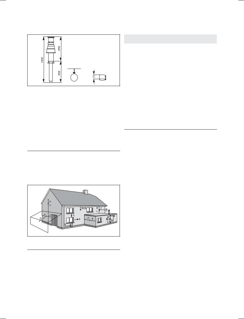
3.5.1Flue termination
The following details refer to both flue systems.
a.The terminal must be located where the combustible substances can escape freely at all times.
b.A plume of water vapour will sometimes be visible from the flue terminal. Positions where this could be a nuisance should be avoided.
c.If the terminal is fitted less than 2 m above a balcony, above ground or above a flat roof to which people have access then a suitable terminal guard must be provided and fitted (made by Tower Flue Components, Tonbridge, TN9 1TB, Model K3, plastic coated).
h Note!Vertical flues must not terminate within
600mm of an openable window, air vent or any other ventilation opening.
The flue assembly shall be so placed or shielded as to prevent ignition or damage to any part of the building.
Fig. 3.6 Terminal locations
h Note!Vertical flues must not terminate within
600mm of an openable window, air vent or any other ventilation opening.
|
Terminal position |
mm |
|
|
|
|
|
A |
Directly below an opening, above an opening or hori- |
300 |
|
zontal to an opening, air brick, opening window, etc. |
|||
|
|
||
B |
Below gutters, soil pipes or drain pipes |
75 |
|
C |
Below eaves |
200 |
|
D |
Below balconies |
200 |
|
E |
From vertical drain pipes and soil pipes |
25 |
|
F |
From internal or external corners |
300 |
|
G |
Above ground, roof or balcony |
300 |
|
H |
From a surface facing a terminal |
600 |
|
I |
From a terminal facing a terminal |
1200 |
|
J |
From an opening in the car port (e.g. door, window) |
1200 |
|
into the dwelling |
|||
|
|
||
K |
Vertically from a terminal on the same wall |
1500 |
|
L |
Horizontally from a terminal on the same wall |
300 |
|
M |
Distance from adjacent wall for vertical Flue |
500 |
Table 3.1 Flue terminal position for a fan assisted concentric flue
The flue assembly shall be so placed or shielded as to prevent ignition or damage to any part of the building.
h Note!In addition, the terminal should not be located closer than 150 mm from a wallopening provided for e.g. a window. Boundary flue terminations must as a minimum comply with Building regulation part „J“ 600 mm and should also be in accordance with the Guide to Condensing Boiler Installation which recommends 2.5 m from wall, fence or boundary.
Where a plume diverter terminal is used this is measured in the direction of the flow of products.
BS 5440–1: It is recommended that the fanned flue terminal should be positioned as follows:
a.at least 2 m from an opening in the building directly opposite, and
b.so that the products of combustion are not directed to discharge across a boundary.
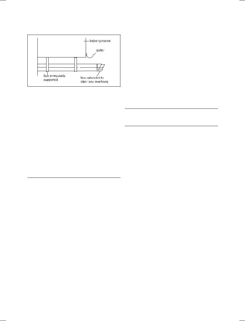
1.Dimensions B, C and D: These clearances may be reduced to 25 mm without affecting the performance of the boiler. In order to ensure that the condensate plume does not affect adjacent surfaces the terminal should be extended as shown in Fig. 3.7.
2.Dimension F: This clearance may be reduced to 25 mm without effecting the performance of the boiler. However, in order to ensure that the condensate plume does not affect adjacent surfaces a clearance of 300 mm is preferred. For IE, recommendations are given in the current edition of IS 813.
12 |
Instructions for installation and servicing ecoTEC plus 0020020828_07 |
General requirements 3
Fig. 3.7 Flue termination under balcony/eves
3.5.2Internal flue installation
The flue can be installed from inside the building when access to the outside wall face is not practicable.
3.6Air supply
Detailed recommendations for air supply are given in
BS 5440: Part 2. It is not necessary to have an air vent in the room or internal space in which the boiler is installed.
3.7Cupboard or compartment ventilation
The boilers are very high efficiency appliances.
As a consequence the heat loss from the appliance casing during operation is very low. For cupboard or compartment installations it is therefore not necessary to provide any high or low level permanent air vents for cooling purposes.
3.8Domestic hot water cylinder
aCaution!
Single feed indirect cylinders are not suitable. The domestic hot water cylinder must be of the double feed fully indirect coil type. It must be suitable for working at a gauge pressure of 0.35 bar above the safety valve setting.
3.8.1Unvented hot water cylinder
The ecoTEC plus can be connected to an unvented hot water cylinder. Vaillant offer a range of cylinders called uniSTOR with capacities from 125 litres to 310 litres. All unvented domestic hot water cylinders must be installed by a competent person approved at the time by the Health and Safety Executive to the current building regulations and water regulations at the time of installation.
For building regulations refer to G3 and for water regulations guidance G17 to G24 and recommendation R17 to R24. For Ireland: The current issue of BS5546 and BS6700. If fitting to an existing system the local authority should be informed.
3.9Condensate drain
A plastic drain pipe must be fitted to allow discharge of condensate to a drain.
Condensate should, if possible, be discharged into the internal household draining system. If this is not practical, discharge can be made externally into the household drainage system or a purpose designed soak away, see Section 4.3.5 for more details.
3.10Heating system controls
It is recommended that a programmer and room thermostat control the boiler. Vaillant have a range of optional easy fit controls available.
Thermostatic radiator valves must be installed, however they must not be fitted in a room where the room thermostat is located.
hNote!
All systems must have at least one radiator not fitted with a thermostatic valve.
hNote!
For further information, see the current issue of the Building Regulations, approved document L1, and the following current issues of:
1.Central heating system specification (CheSS)
2.Controls for domestic central heating system and hot water (BRECSU).
3.11Draining tap
A draining tap must be provided at all the lowest points of the system, which will allow the entire system and hot water system to be drained. Draining taps shall be to the current issue of BS 2879.
3.12Safety valve
A safety valve need not be fitted to an open-vented system.
3.13Bypass
A system bypass will be required fitted at least 1.5 metres away from the boiler, refer to the current issue of central heating system specifications (CHeSS).
3.14Pump specification
The pump should be fitted on the flow pipe from the boiler and have isolating valves each side.
Instructions for installation and servicing ecoTEC plus 0020020828_07 |
13 |

3 General requirements
3.15Cleanser and inhibitor
In the case of an existing installation, it is essential that prior to installing the new boiler the system is thoroughly flushed. For optimum performance after installation of a new system, the boiler and its associated central heating system should also be flushed. Flushing should be carried out in accordance with BS7593: 1992 using a cleanser. For long-term corrosion protection, after flushing, an inhibitor suitable for stainless steel heat exchangers should be used, refer to the current issue of BS 5449 and BS 7593 on the use of inhibitors in central heating systems.
aCaution!
It is essential that the cleanser is fully removed from the system after flushing and before adding inhibitor. Take care to ensure that all low points in the system are fully drained.
Mixing additives with the heating water can result in material damage. However, up to now, no incompatibility with Vaillant appliances has been detected with proper use of the following products.
•When using additives, follow the additive manufacturer‘s instructions without exception.
Vaillant accepts no liability for the compatibility of any additive or its effectiveness in the entire heating system.
Additives for cleaning purposes (subsequent flushing required)
-Fernox F3
-Jenaqua 400
-Sentinel X 300
-Sentinel X 400
Additives intended to remain permanently in the system
-Fernox F1
-Fernox F2
-Sentinel X 100
-Sentinel X 200
Additives for frost protection intended to remain permanently in the system
-Fernox Antifreeze Alphi 11
-Sentinel X 500
•Inform the operator of the necessary measures in case you have used any of these additives.
•Inform the operator of the required procedures for frost protection.
•Observe the applicable national regulations and technical standards for the treatment of filling and top-up
water.
Provided the national regulations and technical standards do not specify any higher requirements, the following applies:
•You must treat the heating water
-if the total volume of filling and top-up water exceeds thrice the nominal volume of the heating sys-
tem over the service life of the system or
-if the limits given in the following tables are not adhered to.
Total heating |
Total hardness at 20 l/kW |
Total hardness at > 20 l/kW |
Total hardness at > 50 l/kW |
output |
for the smallest boiler heating |
< 50 l/kW for the smallest boiler |
for the smallest boiler heating |
|
surface2) |
heating surface2) |
surface2) |
kW |
mol/m3 |
mol/m3 |
mol/m3 |
< 50 |
No requirement or< 3 1) |
2 |
0,02 |
> 50 to≤ 200 |
2 |
1,5 |
0,02 |
> 200 to≤ 600 |
1,5 |
0,02 |
0,02 |
> 600 |
0,02 |
0,02 |
0,02 |
1)with systems equipped with wall-hung boiler and systems with electric heating elements
2)of the specific system volume (nominal capacity in litres/heating output; in case of multiple boiler systems the lowest individual heating output should be used)
These data only apply up to 3x the system volume for filling and top-up water. Once this triple system volume is exceeded, the water will have to be treated exactly the same as in case of exceeding the limit values given in table 3.3 (softening, desalination, hardness stabilisation and desludging).
Table 3.2 Guidelines for the heating water: Water hardness
14 |
Instructions for installation and servicing ecoTEC plus 0020020828_07 |
General requirements 3
Heating water |
Unit |
Low-salt |
saline |
|
qualities |
||||
|
|
|
||
|
|
|
|
|
Electric conductivity |
μS/cm |
< 100 |
100-1500 |
|
at 25 °C |
|
|
|
|
Appearance |
|
Free of sedimentary substances |
||
|
|
|
|
|
pH-value at 25 °C |
|
8,2-10,01) |
8,2-10,01) |
|
Oxygen |
mg/L |
< 0,1 |
< 0,02 |
|
|
|
|
|
|
1)With aluminium and aluminium alloys, the ph value range is restricted from 6.5 to 8.5.
Table 3.3 Guidelines for heating water: Salinity
b Caution!Aluminium corrosion resulting in leakages caused by unsuitable heating water!
Unlike materials such as steel, cast iron or copper, aluminium is reactive to alkalised heating water (pH-value > 8,5) which results in significant corrosion.
With aluminium, ensure that the pH value of the heating water ranges between 6.5 up to a maximum of 8.5.
bCaution!
Risk of material damage if the heating water is treated with unsuitable frost or corrosion protection agents!
Frost and corrosion protection agents may cause changes in the seals, noises during heating and possibly subsequent damage.
Do not use any unsuitable frost or corrosion protection agents.
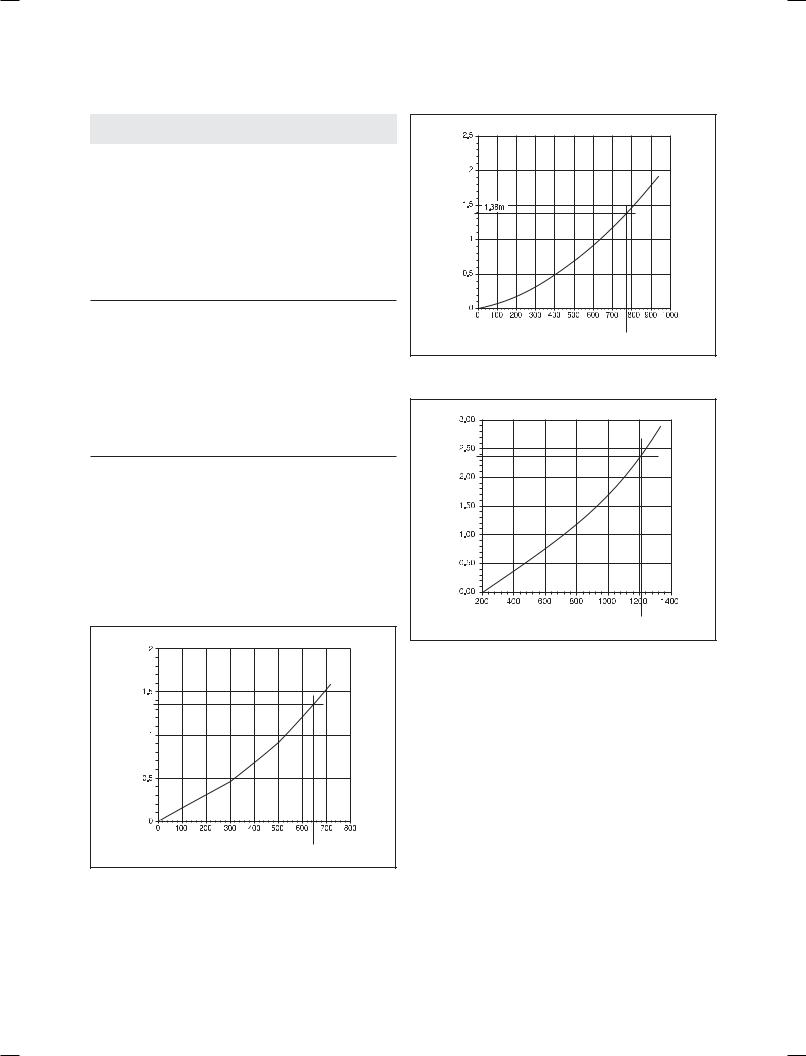
3.16Water pressure loss
Water pressure loss (metres head of water) |
ecoTEC plus 415 pressure loss graph |
|
Flow Rate (litres/hour)
646 l/hr = 20 diff @ 12 kW
Fig. 3.8.1 Pressure loss ecoTEC plus 415
Water pressure loss (metres head of water) |
ecoTEC plus 418 pressure loss graph |
|
Flow Rate (litres/hour)
773.86 l/hr = 20 diff @ 18 kW
Fig. 3.8.2 Pressure loss ecoTEC plus 418
Water pressure loss (metres head of water) |
ecoTEC plus 428 pressure loss graph |
|
Flow Rate (litres/hour)
1220 l/hr = 20 diff @ 30 kW
Fig. 3.8.3 Pressure loss ecoTEC plus 428
Instructions for installation and servicing ecoTEC plus 0020020828_07 |
15 |
3 General requirements
ecoTEC plus 438 pressure loss graph
Water pressure loss (metres head of water)

Flow Rate (litres/hour)
1633 l/hr = 20 diff @ 38 kW
Fig. 3.8.4 Pressure loss ecoTEC plus 438
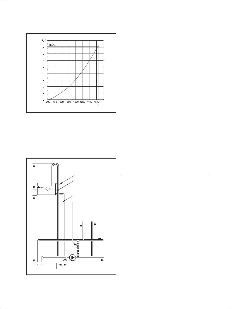
3.17Open vented heating system
The boiler must be supplied from an unrestricted water supply taken from a feed and expansion cistern situated at a maximum height of 27 metres (90ft) above the boiler. The cold feed must be 15mm minimum size. The vent must rise continuously and be unrestricted. It is important that the relative positions of the pump, cold feed and open vent are as shown in fig 3.9.
|
Open (vented) system. |
||||||
450 mm |
Recommended |
||||||
relationship between |
|||||||
(min.) |
pump, cold feed and vent. |
||||||
height |
22 mm (min.) |
||||||
|
|||||||
|
vent feed and |
||||||
|
expansion cistern |
||||||
|
15 mm (min.) cold feed |
||||||
|
15 mm (min.) |
|
|
|
|
|
|
|
automatic by-pass |
||||||
1000 mm |
return |
flow |
|||||
|
|
|
|
|
|
|
|
(min.) |
|
|
|
|
|
|
|
|
cylinder |
|
|
|
|
|
|
|
|
|
|
|
|
|
|
|
|
|
|
|
|
|
|
|
pump |
|
heating |
||||
|
|
|
|
|
|
|
|
boiler |
150 mm (max.) |
|
|
|
|
|
|
|
|
|
|
|
|
||
Fig. 3.9 Open vented system
3.18Sealed water systems
The installation must comply with the appropriate requirements of the current issue of BS4814, BS5449, BS6759, BS6798 and BS7074 Part 1 and 2. For IE your attention is drawn to the current edition of IS 813. It is highly recommend to use the Vaillant Sealed System Kit Article; 020053207 This includes all necessary components and is included in your Vaillant warranty. See also fig 3.10.
3.18.1 Safety valve
A safety valve must be fitted to a sealed system. It shall be preset, non-adjustable with a lift pressure of 3-bar, incorporating seating of a resilient material, a test device and a connection for drain. The safety valve discharge pipe must be routed to outside the building, must not discharge above an entrance or window or any type of public access area, be clear of any electrical fittings and positioned so that any discharge can be seen.
3.18.2 Expansion vessel
A diaphragm type expansion vessel, conforming to the current issue of BS4814 (see also BS7074 Part 1 and 2). For IE the current edition of IS 813, must be connected at a point close to the inlet side of the circulating pump, see the Typical installation, Fig. 3.10. unless laid down differently by the manufacturer. The expansion vessel volume depends on the total water system volume and the initial system design pressure. For any system an accurate calculation of vessel size is given in the current issue of BS5449 and BS7074 Part 1. Example: For an initial design pressure of 0.7 bar, the minimum total vessel volume required is 0.063 x Total System Volume.
h Note!A higher initial design pressure requires a larger volume expansion vessel.
The charge pressure must not be less than the static head of the system, that is, the height of the highest point of the system above the expansion vessel.
3.18.3 Pressure gauge
A pressure gauge with a set pointer and covering at least 0 to 4 bar (0 to 60 lb/in2) shall be fitted permanently to the system in a position where it can be seen when filling the system.
3.18.4 Water make up
Provision should be made for replacing water loss from the system using a make up bottle mounted in a position higher than the top point of the system, connected through a non-return valve to the return side of either the heating circuit or the hot water cylinder. Alternatively, provision for make up water should be made using a proprietary filling loop.
16 |
Instructions for installation and servicing ecoTEC plus 0020020828_07 |
 Loading...