


 Loading...
OPERATOR / ILLUSTRATED PARTS MANUAL
FS300 SERIES, PLAIN AND DIFFERENTIAL FEED,
HIGH SPEED FLAT BED MACHINES
MANUAL NO. PT9914
FOR STYLES
FS315L63
FS316L61
FS316L62
FS316L63
08-20-08

Manual No. PT9914 llustrated Parts List for FS300 Series Machines
First Edition Copyright 2000
By
Union Special Corporation Rights Reserved In All Countries
Printed in U.S.A. Jan. 2000
PREFACE
This parts manual has been prepared to assist you in locating individual parts or assemblies on FS300 Series machines. It can be used in conjunction with Union Special Engineer's Manual EN9424.
It is the desire of Union Special that each machine run at its optimum performance. Parts listed in this manual are designed specifically for your machine and are manufactured with utmost precision to assure long lasting service.
This manual has been comprised on the basis of available information. Changes in design and/or improvements may incorporate a slight modification of configuration in illustrations or part numbers.
On the following pages are illustrations and terminology used in describing the parts used on FS300 Series machines.
CONTENTS |
|
PREFACE .................................................................................................................................................................... |
2 |
IDENTIFICATION OF MACHINES ............................................................................................................................... |
4 |
CLASS DESCRIPTION ................................................................................................................................................. |
4 |
STYLE OF MACHINES ................................................................................................................................................. |
4 |
STYLE OF MACHINES CONT. .................................................................................................................................... |
5 |
ILLUSTRATIONS........................................................................................................................................................... |
5 |
IDENTIFYING PARTS ................................................................................................................................................... |
5 |
NEEDLES..................................................................................................................................................................... |
5 |
SAFETY RULES ............................................................................................................................................................ |
6 |
FS300 SERIES BUILDING BLOCK STYLE DESIGNATION SYSTEM................................................................................ |
7 |
CAUTION AREAS: ...................................................................................................................................................... |
8 |
OPERATOR'S DAILY CHECK LIST:.............................................................................................................................. |
9 |
OPERATING CAUTIONS: ........................................................................................................................................... |
9 |
OPERATING CAUTIONS (CONT.): .......................................................................................................................... |
10 |
OPERATING THE PEDALS: ....................................................................................................................................... |
10 |
LUBRICATION: ......................................................................................................................................................... |
11 |
THREADING THE MACHINE: ................................................................................................................................... |
12 |
THREADING THE MACHINE (CONT.): .................................................................................................................... |
13 |
THREADING METHODS ........................................................................................................................................... |
14 |
ADJUSTING THE STITCH LENGTH: ........................................................................................................................... |
15 |
PRESSER FOOT PRESSURE AND LIFTER: .................................................................................................................. |
15 |
FEED, NEEDLE LOOPER TIMING:............................................................................................................................. |
16 |
NEEDLE ALIGNMENT: .............................................................................................................................................. |
16 |
LOOPER SETTING:.................................................................................................................................................... |
17 |
NEEDLE BAR SETTING: ............................................................................................................................................. |
17 |
2

REAR NEEDLE GUARD: ........................................................................................................................................... |
18 |
FEED DOG CENTERING AND HEIGHT ABOVE THROAT PLATE: ............................................................................ |
18 |
PRESSER FOOT: ........................................................................................................................................................ |
18 |
LOOPER THREAD TAKE-UP CAM SETTING: ............................................................................................................ |
19 |
THREAD CONTROL: ................................................................................................................................................ |
19 |
PULLER ADJUSTMENTS: ........................................................................................................................................... |
20 |
PULLER ADJUSTMENTS CONT.: ............................................................................................................................... |
21 |
BUSHINGS ................................................................................................................................................................ |
23 |
NEEDLE BAR ............................................................................................................................................................ |
25 |
UPPER MAIN SHAFT ................................................................................................................................................. |
27 |
THREAD GUIDE ........................................................................................................................................................ |
29 |
TENSION RELEASE & THREAD TENSION .................................................................................................................. |
31 |
PRESSER FOOT LIFT .................................................................................................................................................. |
33 |
COVERS, UPPER ARM ............................................................................................................................................ |
35 |
LOWER MAIN SHAFT ............................................................................................................................................... |
37 |
LUBRICATION, OIL TUBING & OIL PUMP ................................................................................................................ |
39 |
LOOPER DRIVE ........................................................................................................................................................ |
41 |
NEEDLE GUARD ...................................................................................................................................................... |
43 |
LOOPER THREAD TAKE-UP ..................................................................................................................................... |
45 |
FEED DRIVE MECHANISM FOR PLAIN FEED .......................................................................................................... |
47 |
FEED DRIVE MECHANISM FOR DIFFERENTIAL FEED .............................................................................................. |
49 |
FEED DRIVE MECHANISM FOR PLAIN FEED .......................................................................................................... |
51 |
FEED DRIVE MECHANISM FOR DIFFERENTIAL FEED .............................................................................................. |
53 |
COVERS, LOWER BED............................................................................................................................................. |
55 |
COVERS, LOWER BED............................................................................................................................................. |
57 |
SEWING PARTS ........................................................................................................................................................ |
59 |
FOLDERS .................................................................................................................................................................. |
61 |
PULLER DRIVE ASSEMBLY ........................................................................................................................................ |
63 |
PULLER ASSEMBLY ................................................................................................................................................... |
65 |
PULLER ASSEMBLY ................................................................................................................................................... |
67 |
MISCELLANEOUS PARTS PA1 (USE WITH CC2 CHAIN CUTTER) ........................................................................... |
69 |
MISCELLANEOUS PARTS PA1A (USE WITHOUT CC2 CHAIN CUTTER) .................................................................. |
71 |
TUBING PA1 WITH CHAIN CUTTER ......................................................................................................................... |
72 |
TUBING PA1A WITHOUT CHAIN CUTTER ................................................................................................................ |
73 |
TABLING (EXTRA SEND CHARGE) .......................................................................................................................... |
75 |
PRESSER FOOT LIFTER .............................................................................................................................................. |
77 |
ACCESSORIES ......................................................................................................................................................... |
79 |
NUMERICAL INDEX OF PARTS ................................................................................................................................ |
80 |
NUMERICAL INDEX OF PARTS ................................................................................................................................ |
81 |
3

IDENTIFICATION OF MACHINES
Each UNION SPECIAL machine is identified by a style number, which is stamped into the style plate affixed to the middle of the machine under the tension assembly. The serial number is stamped into the serial number plate affixed to the right rear base of the machine.
CLASS DESCRIPTION
Precision high speed, single needle, plain or differential feed flat bed machines. Totally enclosed feed and looper drive mechanism, automatic forced feed lubrication system with easily replaceable filter. Main feed has thumbscrew adjustment and differential feed has lever adjustment and independently driven rear needle guard.
|
STYLE OF MACHINES |
FS316L61-3H36CC2PA1 |
DOUBLE LAP SEAM. Three needle, plain feed, high capacity, flat sewing parts, close- |
|
coupled toothed roller puller, pneumatic power "AIR-KLIPP" Chain cutter, pneu |
|
matic assisted presser foot and roller lift, and double lap seam folder with 1/8" |
|
(3.2mm) capacity. For attaching the risers to jeans, seat seaming operations on |
|
jeans, bibs to overalls and piecing sleeves on denim jackets. Seam Specifications |
|
401LSc-3. Recommended needle 128 GAS sizes 140/054 - Stitch range 7-10 S.P.I.. |
|
Maximum recommended speed 6000 R.P.M. |
FS316L61-3H36PA1 |
DOUBLE LAP SEAM. Three needle, plain feed, high capacity, flat sewing parts, close- |
|
coupled toothed roller puller, pneumatic assisted presser foot and roller lift, and |
|
double lap seam folder with 1/8" (3.2mm) capacity. For attaching the risers to jeans, |
|
seat seaming operations on jeans, bibs to overalls and piecing sleeves on denim |
|
jackets. Seam Specifications 401LSc-3. Recommended needle 128 GAS sizes 140/ |
|
054 - Stitch range 7-10 S.P.I.. Maximum recommended speed 6000 R.P.M.. |
FS316L62-3H36CC2PA1 |
DOUBLE LAP SEAM. Three needle, plain feed, high capacity, .040" stepped chaining |
|
sewing parts, close-coupled toothed roller puller, pneumatic power "AIR-KLIPP" |
|
Chain cutter, pneumatic assisted presser foot and roller lift, and double lap seam |
|
folder with 1/8" (3.2mm) capacity. For attaching the risers to jeans, seat seaming |
|
operations on jeans, bibs to overalls and piecing sleeves on denim jackets. Seam |
|
Specifications 401LSc-3. Recommended needle 128 GAS sizes 140/054 - Stitch |
|
range 7-10 S.P.I.. Maximum recommended speed 6000 R.P.M.. |
FS316L62-3H36PA1 |
DOUBLE LAP SEAM. Three needle, plain feed, high capacity, .040" stepped chaining |
|
sewing parts, close-coupled toothed roller puller, pneumatic assisted presser foot |
|
and roller lift, and double lap seam folder with 1/8" (3.2mm) capacity. For attaching |
|
the risers to jeans, seat seaming operations on jeans, bibs to overalls and piecing |
|
sleeves on denim jackets. Seam Specifications 401LSc-3. Recommended needle |
|
128 GAS sizes 140/054 - Stitch range 7-10 S.P.I.. Maximum recommended speed |
|
6000 R.P.M.. |
FS316L63-3H32CC2PA1 |
DOUBLE LAP SEAM. Three needle, plain feed, high capacity, .070" stepped chaining |
|
sewing parts, close-coupled toothed roller puller, pneumatic power "AIR-KLIPP" |
|
Chain cutter, pneumatic assisted presser foot and roller lift, and double lap seam |
|
folder with 1/8" (3.2mm) capacity. For attaching the risers to jeans, seat seaming |
|
operations on jeans, bibs to overalls and piecing sleeves on denim jackets. Seam |
|
Specifications 401LSc-3. Recommended needle 128 GAS sizes 140/054 - Stitch |
|
range 7-10 S.P.I.. Maximum recommended speed 6000 R.P.M.. |
FS316L63-3H32PA1 |
DOUBLE LAP SEAM. Three needle, plain feed, high capacity, .070" stepped chaining |
|
sewing parts, close-coupled toothed roller puller, pneumatic assisted presser foot |
|
and roller lift, and double lap seam folder with 1/8" (3.2mm) capacity. For attaching |
|
the risers to jeans, seat seaming operations on jeans, bibs to overalls and piecing |
|
sleeves on denim jackets. Seam Specifications 401LSc-3. Recommended needle |
|
128 GAS sizes 140/054 - Stitch range 7-10 S.P.I.. Maximum recommended speed |
|
6000 R.P.M.. |
4

|
STYLE OF MACHINES CONT. |
FS315L63-3H32CC2PA1 |
Same as FS316L63-3H32CC2PA1 except differential feed. |
FS315L63-3H32PA1 |
Same as FS316L63-3H32PA1 except differential feed. |
ILLUSTRATIONS
This manual has been arranged to simplify ordering repair parts. Exploded views of various sections of the mechanism are shown so that the parts may be seen in their actual position in the machine. On the page opposite the illustration will be found a listing of the parts with their part numbers, description and the number of pieces required in the particular view being shown.
Numbers in the first column are reference numbers only, and merely indicate the position of the part in the illustration. The reference number should never be used in ordering parts. Always use the part number listed in the second column.
Component parts of sub-assemblies which can be furnished for repairs are indicated by indenting their descriptions under the description of the main sub-assembly. As an example refer to the following text.
5. |
50366B |
Needle Thread Strike-Off Assembly ................................................................................ |
1 |
6. |
50358V |
Needle Thread Strike-Off .................................................................................. |
1 |
7. |
50370F |
Thread Strike-Off Component ......................................................................... |
1 |
8. |
SS7060310SP |
Screw, for plate strike-off .................................................................................. |
1 |
When a part is common to all machines covered in this manual, no specific usage will be mentioned in the description. However, when the parts for the various machines are not the same, the specific usage will be mentioned in the description and, if necessary, the difference will be shown in the illustration.
*Ref. No. showing no Part No. is for location only. Part is not for sale separately.
A numerical index of all the parts shown in this manual is located at the back. This will facilitate locating the illustration and description when only a part number is known.
IDENTIFYING PARTS
Where construction permits, each part is stamped with its part number. On some of the smaller parts and on those where construction does not permit, an identification letter is stamped in to distinguish the part from similar ones.
PLEASE NOTE: |
Part numbers represent the same part, regardless of which manual they appear. On all orders please include |
|
part number, name and style of machine for which the part was ordered. |
For optimum performance use only genuine Union Special replacement parts.
NEEDLES
Each needle has both a type and size number. The type number denotes the kind of shank, point, length, groove, finish and other details. The size number, stamped on the needle shank, denotes the largest diameter of the blade measured between the shank and the eye. Collectively, the type number and size number represent the complete symbol which is given on the label of all needles packed and sold by Union Special.
TYPE |
DESCRIPTION |
128 GAS |
Short, double groove, struck groove, ball eye, spotted, round point, chromium platedSizes available 080/032, |
|
090/036, 100/040, 110/044, 125/049, 150/060. |
When changing the needle, make sure it is fully inserted in the needle holder before the screw is tightened.
When ordering needles, please use the complete type and size numbers as printed on the package to ensure prompt and accurate processing of your order. A complete order should read as follows: "100 needles, type 128 GAS, size 150/060".
5

SAFETY RULES
1.Before putting the machines described in this manual into service, carefully read the instructions. The starting of each machine is only permitted after taking notice of the instructions and by qualified operators.
IMPORTANT! Before putting the machine into service, also read the safety rules and instructions from the motor supplier.
2.Observe the national safety rules valid for your country.
3.The sewing machines described in this instruction manual are prohibited from being put into service until it has been ascertained that the sewing units which these sewing machines will be built into, have conformed with the EC Council Directives (89/392/EEC, Annex II B).
Each machine is only allowed to be used as foreseen. The foreseen use of the particular machine is described in paragraph “STYLES OF MACHINES” of this instruction manual. Another use, going beyond the description, is not as foreseen.
4.All safety devices must be in position when the machine is ready for work or in operation. Operation of the machine without the appertaining safety devices is prohibited.
5.Wear safety glasses.
6.In case of machine conversions and changes all valid safety rules must be considered. Conversions and changes are made at your own risk.
7.The warning hints in the instructions are marked with one of these two symbols:
8.When doing the following the machine has to be disconnected from the power supply by turning off the main switch or by pulling out the main plug:
8.1When threading needle(s), looper, spreader etc.
8.2When replacing any parts such as needle(s), presser foot, throat plate, looper, spreader, feed dog, needle guard, folder, fabric guide etc.
8.3When leaving the workplace and when the workplace is unattended.
8.4When doing maintenance work.
8.5When using clutch motors without actuation lock, wait until the motor is stopped totally.
9.Maintenance, repair and conversion work (see item 8) must be done only by trained technicians or special skilled personnel under consideration of the instructions.
10.Any work on the electrical equipment must be done by an electrician or under direction and supervision of special skilled personnel.
11.Work on parts and equipment under electrical power is not permitted. Permissible exceptions are described in the applicable sections of standard sheet DIN VDE 0105.
12.Before doing maintenance and repair work on the pneumatic equipment, the machine has to be disconnected from the compressed air supply. In case of existing residual air pressure, after disconnecting from compressed air supply (i.e. pneumatic equipment with air tank), the pressure has to be removed by bleeding.
6
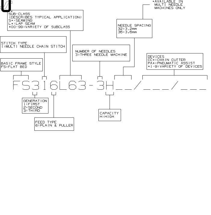
FS300 SERIES BUILDING BLOCK STYLE DESIGNATION SYSTEM
7
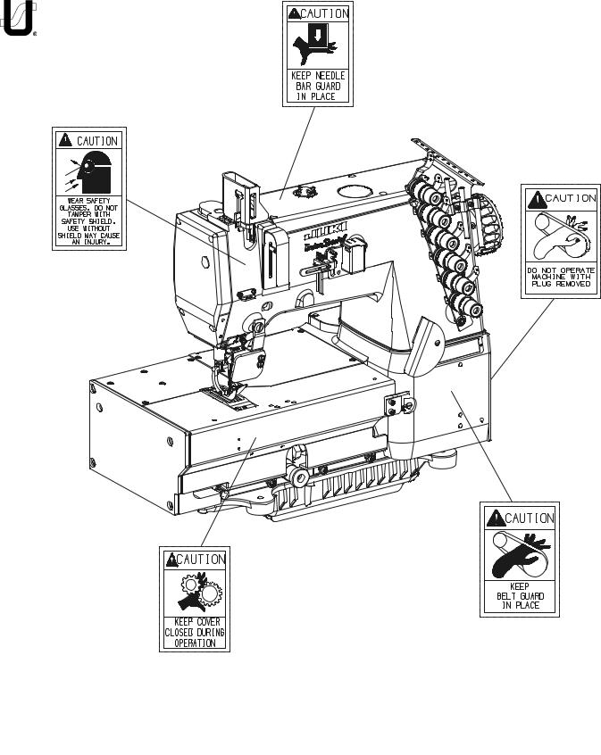
CAUTION AREAS:
8
OPERATOR'S DAILY CHECK LIST:
The following should be checked daily and cleaned as required when it applies to your Union Special machine:
••Lint area (clean with compressed air or brush) ••Needle bar bushings
••Under feed dogs & throat plates ••In knives
••In thread control eyelets
••Cooling airways ••In the machine ••In the motor
••In the cooling package
(package is an extra send charge)
1.The oil level in the sight gauge should be between the two red lines when the machine is at rest. If not, fill with Union Special Specification 175 oil, (Union Special Part No. 28604R).
2.The correct rotating direction of the handwheel is counterclockwise, as viewed from the handwheel's side. NEVER run the machine in reverse direction.
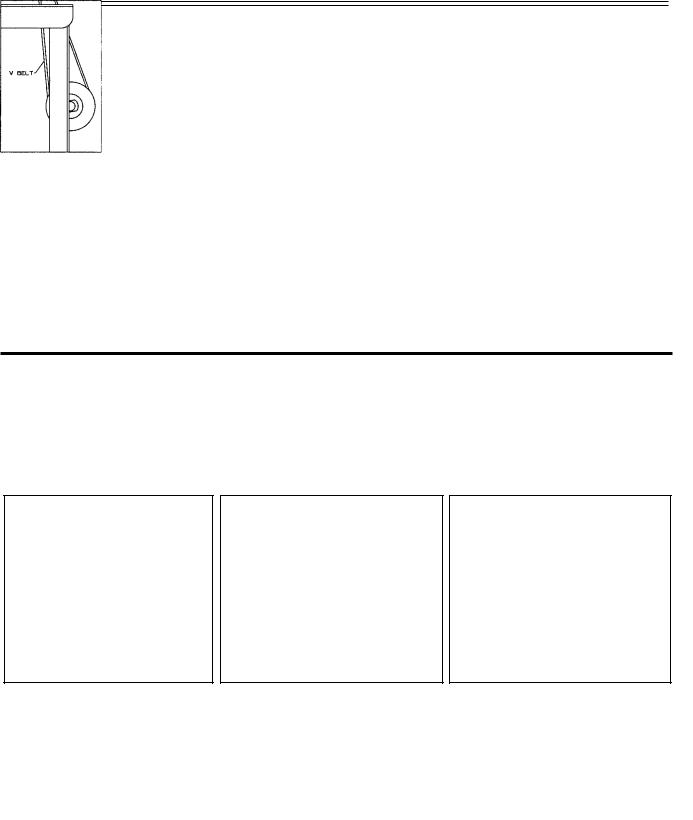
OPERATING CAUTIONS:
1. Do not put your hand under 2. |
Do not put your hand into the 3. |
Turn off the power switch and |
the needles when turning on |
sewing area while the machine |
make sure the clutch motor is |
the power switch or at any |
is running. |
at rest before removing the V |
time. |
|
belt. |
9

OPERATING CAUTIONS (CONT.):
4.During operation, do not allow head, hands or any instrument, tool etc. near handwheel, V belt and motor.
5.Do not operate your machine without the proper belt guard, sewing guards or any other protectors that have been provided. Doing so is very dangerous.
6.Before inspecting, adjusting, cleaning, threading the head or replacing needles, turn OFF the power switch. Make sure the flywheel on the motor has stopped, it will be kept running by inertia after turning OFF the power switch. DO NOT depress the foot pedal while the machine is running or it will cause the machine to rotate abruptly.
7.Turn OFF the power switch when you leave your machine or in case of a power failure.
8.Do not wipe the machine surface with lacquer thinner.
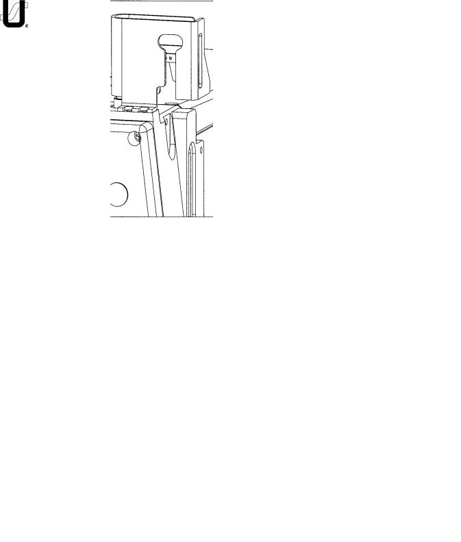
OPERATING THE PEDALS:
1.Locate the center of drive treadle (A) to be in line with the needles.
2.Locate presser lifter pedal (B) for operator comfort.
3.Use S-shaped hook (C) to connect presser lifter pedal chain (D) to presser lifting lever (E).
10
LUBRICATION:
The oil should be between the two red lines in sight gauge (B) when the machine is at rest.
1.If oil is required remove oil cap (A).
2.Fill between lines (B) with Union Special Specification 175 oil (Union Special Part No. 28604R).
CAUTION! Do not exceed the upper red marker line. Excessive oil in the machine will result in oil leakage and possible overheating.
3.To drain oil reservoir, remove oil drain cap (C) on the underside of the machine.
4.To ensure oil flow through machine, check oil flow window (D).
11

THREADING THE MACHINE:
Turn off main power switch before threading! When using clutch motors without actuation lock wait until the motor has completely stopped.
Thread the machine according to the following threading illustrations.
12
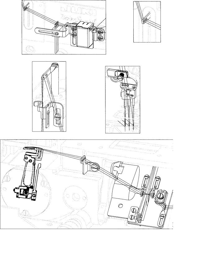
THREADING THE MACHINE (CONT.):
13

threading the machine (cont.):
When the needle thread lubricator is used:
1.Saturate felt (A).
2.Pass thread over felt.
When the needle thread lubricator is not used:
1.Remove felt (A).
The standard needle is 128 GAS, needle range sizes "090/036 - 150/060."
Insert needle according to the following procedure:
1.Bring needle head (A) to the highest position.
2.Loosen screw (B), insert needle into holes. The needle scarf should face rearwards as viewed from the operator's side.
3.Retighten screw (B).
THREADING METHODS
CAUTION!
When using an untwisted thread such as wooly nylon or weak thread, do not wind it around the intermediate thread guide.
14
PRESSER FOOT PRESSURE AND LIFTER:
1.Adjust presser foot pressure by loosening nut (A) and turning presser foot adjust screw (B) clockwise to increase the pressure, counterclockwise to decrease the pressure.
2.Retighten nut (A).
ADJUSTING THE STITCH LENGTH:
Turn off main power switch before setting the stitch length! When using clutch motors without actuation lock wait until the motor has completely stopped.
1.To change stitch length turn stitch regulating screw (A).
Clockwise to increase the stitches per inch/shorten the length of one stitch.
Counterclockwise to decrease stitches per inch/increase the length of one stitch.
2.Numbers 0-11 on stitch regulating screw are for operator's reference only.
15

FEED, NEEDLE LOOPER TIMING:
Set the first screw in operating direction of the feed drive eccentrics to be straight up, then, holding this position, set the needle bar at B.D.C.. Set the looper timing to the needles to be synchronized. Adjust the looper timing with the looper avoid drive sprocket.
NEEDLE ALIGNMENT:
Torque needle head to 14 to 16 in-lbs (1.6 to 1.8Nm).
Install the feed dog, needles and throat plate. Use the adjustable ferrules to align the needles in the throat plate and align the feed dog so it is centered side to side. tighten the throat plate support and ferrules in place.
16
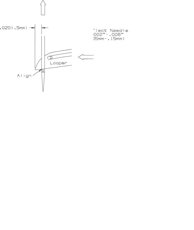
LOOPER SETTING:
Use the right needle and looper to set the looper gauge. Set the looper gauge to 1/8" (3.2mm)when loopers at extreem right. Set the loopers front to back to deflect the needles forward .002" to .006" (.05mm to
.10mm). set the looper avoid so the needle touches the back of the looper 2/3 down back as needles decend.
NEEDLE BAR SETTING:
Set the needle height so when the top of the needle eye is even with the bottom of the looper (on it's travel to the left) the looper tip is .020" (.5mm) past the needle. Use the left needle. Recheck looper setting. Torque needle bar clamp screw to the following specifications:
Torque needle bar@
18 to 20 in.-lbs. (2.0 to 2.3Nm)
17
REAR NEEDLE GUARD:
Set the timing of the rear needle guard so the guard reaches it's furthest travel forward as the loopers enter the scarfs on the travel to the left.
Bring the looper tips to the center of the needles in the scarf. The tip of the needles should be 3/64" +/-1/64" (1.2mm +/-.4mm) below the top guarding surface. The guard should just touch the needles up to
.002 (.05mm) deflection. The loopers when traveling to the left should just touch the needles to .002" (.05mm) clearance when entering the scarf area.
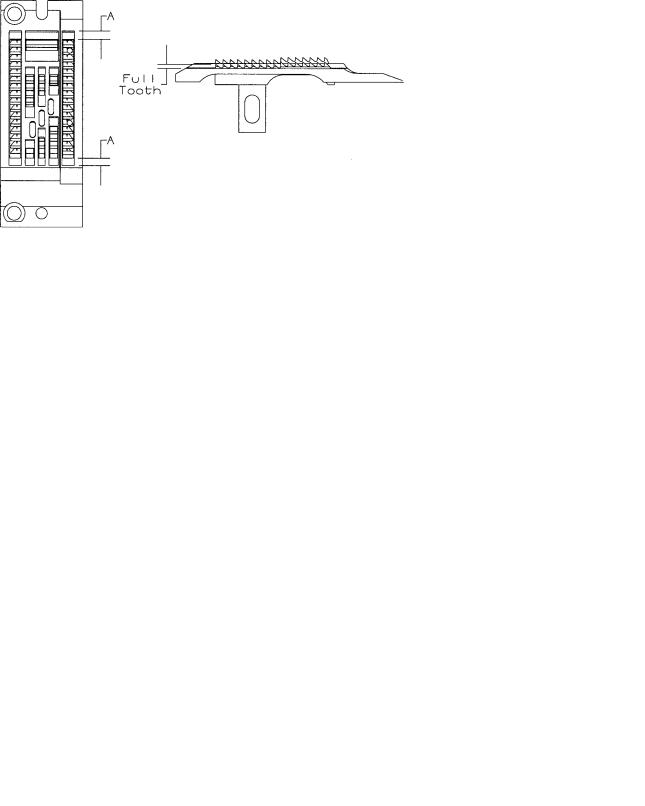
FEED DOG CENTERING AND HEIGHT ABOVE THROAT PLATE:
Set the machine to its longest stitch length. Center feed dog, front to back, so as to obtain equal clearance on the front side and back side of feed dog in the throat plate slots. Set the feed dogs to come out of the throat plate level. Set feed dog height to be full tooth at the rear when the feed dog is at the top of its stroke.
PRESSER FOOT:
Center the needles in the presser foot needle slots. The presser foot lifter lever stop should be set to when the foot is lifted it does not interfere with the needle head when the needle bar is down.
18
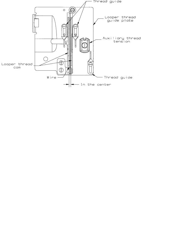
LOOPER THREAD TAKE-UP CAM SETTING:
The looper thread cam should be set so that the looper threads cast off the high lobe of the cam as the point of the needles are just even with the under side of the looper. Set the cast-off plate eyelets so that when the looper reaches its left end of travel, all of the looper thread is used and no thread is drawn from the cone. Move down for less. Set the retaining finger so that the finger is even with the bottom edge of its holder and the tip on the right side is touching the cast-off plate.
THREAD CONTROL:
Set the individual needle thread eyelets so they are 25mm below the top casting and to the extreme right when using the mount adapter.
19
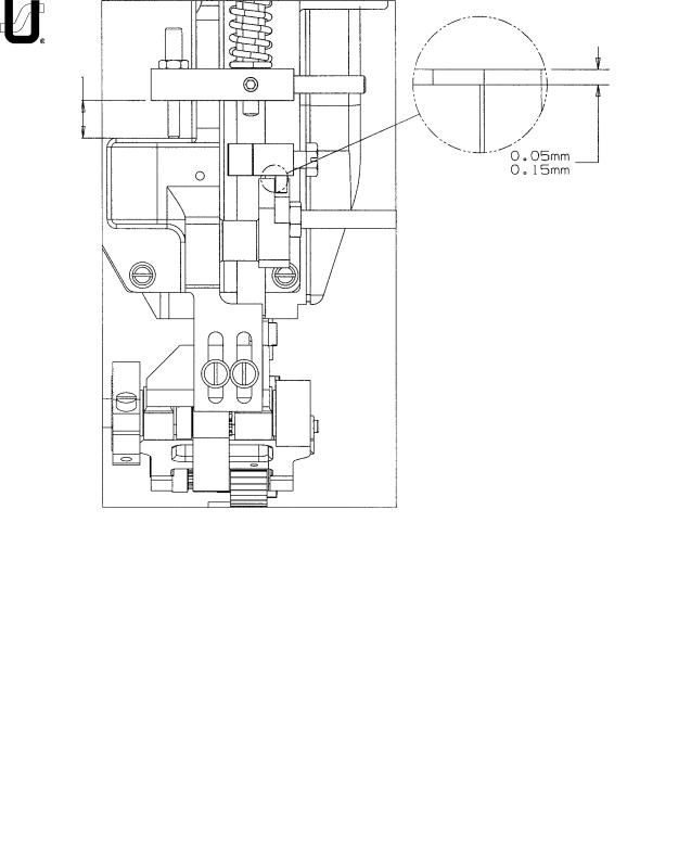
PULLER ADJUSTMENTS:
With the roller resting on the top of the throat plate, the stop collar should be set about 15mm above the ledge of the puller casting where the stop screw rests. Set the stop screw to rest on the casting and lock in place. Set the lifter lever block to have 0.05mm to 0.15mm clearance above the lifter lever in the neutral position.
Note: When changing sprockets, if the total number of teeth on both sprockets is differentthan what was on the puller, check and readjust these settings.
Use the puller tension nut to add or remove pressure frm the roller.
20
PULLER ADJUSTMENTS CONT.:
When assembeling the puller to the machine, make sure that a minimum of
.05 clearence is maintained between the roller and the throat plate step. Also the roller must sit flat on the throat plate.
Time the puller so the roller feeds at the same time the feed dog is feeding. When setting, both should be feeding at the same S.P.I.. Adjust the timing by using the sprocket on the upper main shaft in the arm.
PULLER SPROCKET COMBINATIONS
PULLER DRIVE |
PULLER |
S.P.I. ±1/2 |
SPROCKET |
SPROCKET |
STITCH |
|
|
|
14 |
15 |
8 |
|
|
|
14 |
14 |
7 1/2 |
|
|
|
15 |
14 |
7 |
|
|
|
15 |
13 |
6 1/2 |
|
|
|
13 |
15 |
8 1/2 |
|
|
|
13 |
16 |
9 |
|
|
|
16 |
13 |
6 |
|
|
|
12 |
16 |
9 1/2 |
|
|
|
11 |
16 |
10 |
|
|
|
21
22

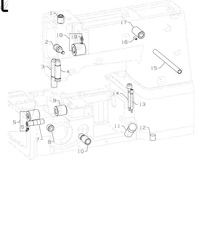
BUSHINGS
Ref. |
|
|
Amt. |
No. |
Part No. |
Description |
Req. |
1. |
50654 |
Bushing, for needle bar, upper ..................................................................... |
1 |
2. |
50332U |
Pin, for front lifter lever .................................................................................. |
1 |
3. |
50330CZ |
Bushing, for presser bar ................................................................................ |
1 |
4. |
50654A |
Bushing, for needle bar, lower ...................................................................... |
1 |
5. |
50344BE |
Bushing, for lower mainshaft, left ................................................................. |
1 |
6. |
SQ1110401MZ |
Fitting ..................................................................................................... |
1 |
7. |
50344BC |
Bushing, for needle lever .............................................................................. |
1 |
8. |
50344E |
Bushing ........................................................................................................ |
1 |
9. |
50344BF |
Bushing, for lower mainshaft, right ............................................................... |
1 |
10. |
35036BS |
Stitch Regulator Bushing .............................................................................. |
1 |
11. |
50393GE |
Oil Sight Gauge ............................................................................................ |
1 |
12. |
22571L |
Screw, for drain plug .................................................................................... |
1 |
13. |
50393FU |
Fitting, oil tube .............................................................................................. |
1 |
14. |
50393EY |
Fitting, filter .................................................................................................. |
1 |
15. |
50392AB |
Bushing, for tension release.......................................................................... |
1 |
16. |
PS0400142KH |
Pin ................................................................................................................ |
1 |
17. |
50381E |
Bushing, for lifter lever, back ........................................................................ |
1 |
18. |
50344BU |
Bushing, front ............................................................................................... |
1 |
19. |
SQ1110401MZ |
Fitting ..................................................................................................... |
1 |
23
24

|
|
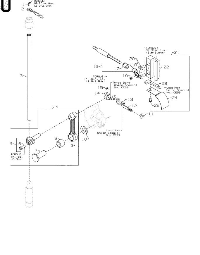
NEEDLE BAR |
|
Ref. |
|
|
Amt. |
No. |
Part No. |
Description |
Req. |
1. |
SS4080620TP |
Screw ........................................................................................................... |
1 |
2. |
50323P |
Needle Bar Eyelet ......................................................................................... |
1 |
3. |
50317B |
Needle Bar ................................................................................................... |
1 |
4. |
50345W |
Connecting Rod Assembly ........................................................................... |
1 |
5. |
50355AM |
Needle Bar Clamp ................................................................................. |
1 |
6. |
SS7111120TP |
Screw ............................................................................................... |
1 |
7. |
50352 |
Pivot Pin ................................................................................................. |
1 |
8. |
661-259B |
Needle Bearing Cage ............................................................................ |
1 |
9. |
50355AN |
Connecting Rod .................................................................................... |
1 |
10. |
50351A |
Washer ......................................................................................................... |
1 |
11. |
50393JP |
Eyelet Seal .................................................................................................... |
1 |
12. |
50358X |
Needle Thread Eyelet ................................................................................... |
1 |
13. |
SS7080520SP |
Screw ........................................................................................................... |
1 |
- |
CE27 |
Loctite Adhesive, (not shown), for screw ..................................................... |
- |
14. |
50354F |
Slide Block .................................................................................................... |
1 |
- |
CE63 |
Three Bond Adhesive, (not shown), for slide block ....................................... |
- |
15. |
SS8110422TP |
Screw ........................................................................................................... |
1 |
16. |
29476TC |
Oil Tube Assembly ........................................................................................ |
1 |
17. |
50393JZ |
Oil Tube ........................................................................................................ |
1 |
18. |
50393JW |
Hose Clamp ................................................................................................. |
1 |
19. |
SS6090440SP |
Screw, for oil tube assembly ......................................................................... |
1 |
20. |
SS6121010SP |
Screw ........................................................................................................... |
2 |
21. |
29476VN |
Slide Block Guide and Cover Assembly ........................................................ |
1 |
22. |
50338 |
Guide, for slide block ............................................................................. |
1 |
23. |
666-328 |
Felt, for slide block .................................................................................. |
1 |
- |
CE59 |
Loctite Adhesive, (not shown), for felt ................................................... |
- |
24. |
50338A |
Cover, for guide ..................................................................................... |
1 |
25. |
SS6090620SP |
Screw ..................................................................................................... |
1 |
25

26
Loading...