


39500 Maximum Performance 9M Series
Maximum
Performance
9M
Series
-High
speed
overedge
machines
CATALOG
NO.
IO3XQA
First
Edition
SERIES
9M
Adjusting
instructions
and
illustrated
parts
list
U,
U
Finest
Quality
Zua
Equipment
From the library of: Superior Sewing Machine & Supply LLC
CATALOG
NO.
103
XQA
ADJUSTING
INSTRUCTIONS
AND
ILLUSTRATED
PARTS
LIST
FOR
MAXIMUM
PERFORMANCE
-
9M
SERIES
STYLES
39500
XQA
39500
XRN
39500
CXQJ
39500
XQB
39500
XSD
39500
CXRN
39500
XQJ
39500
XTA
39500
CXSD
39500
XRB
39500
CXQA
39500
XSQB
39500
XRC
39500
CXQB
39500
CXSQB
First
Edition
Copyright
1983
By
Union
Special
Corporation
Rights
Reserved
in
All
Countries
Printed
in
U.S.A.
January
1983
2
From the library of: Superior Sewing Machine & Supply LLC
FORE
WARD
This
technical
manual
has
been
prepared
to
guide
you
in
the
maintenance
of
your
new
UNION
SPECIAL
machine.
Careful
attention
to
the
instructions
for
oper
ating
and
adjusting
these
machines
will
enable
you
to
maintain
the
superior
per
forinance
and
reliability
designed
and
built
into
every
UNION
SPECIAL
machine.
The
Adjusting
Instruction
portion
of
this
manual
explains
in
detail
the
proper
setting
for
each
of
the
components
related
to
forming
the
stitch
and
com
pleting
the
functions
of
the
machine.
Figures
are
used
to
illustrate
the
adjust
ments
using
reference
letters
to
point
out
specific
items
discussed.
Adjustments
are
presented
in
sequence
so
that
a
logical
progression
is
accom
plished.
Some
adjustments
performed
out
of
sequence
may
have
an
adverse
effect
on
the
function
of
other
related
parts.
Implementation
of
preventative
maintenance
procedures
can
bring
about
signi
ficant
improvements
in
operator
productivity
by
avoiding
costly
equipment
break
downs.
Whenever
it
becomes
necessary
to
make
repairs
or
replace
parts
on
your
machine,
be
sure
to
insist
on
genuine
UNION
SPECIAL
Repair
Parts.
These
parts
are
designed
specifically
for
your
machine
and
manufactured
with
utmost
precision
to
assure
long
lasting
service.
To
simplify
indentification
of
epair
parts,
the
mechanisms
are
illustrated
by
exploded
views.
These
illustrations
will
usually
be
shown
in
conjuction
with
a
KEY
VIEW
which
presents
the
mechanisms
of
the
machine
assembled.
The
specific
parts
illustrated
on
this
page
will
appear
shaded
in
the
KEY
VIEW.
3
From the library of: Superior Sewing Machine & Supply LLC
IDENTIFICATION
OF
MACHINES
Each
UNION
SPECIAL
machine
carries
a
style
number,
which
on
this
class
machine
is
stamped
in
the
style
plate
located
on
the
right
rear
of
the
machine.
Serial
number
is
stamped
in
the
extension
of
bed
casting
at
the
right
rear
base
of
machine.
STYLES
OF
MACHINES
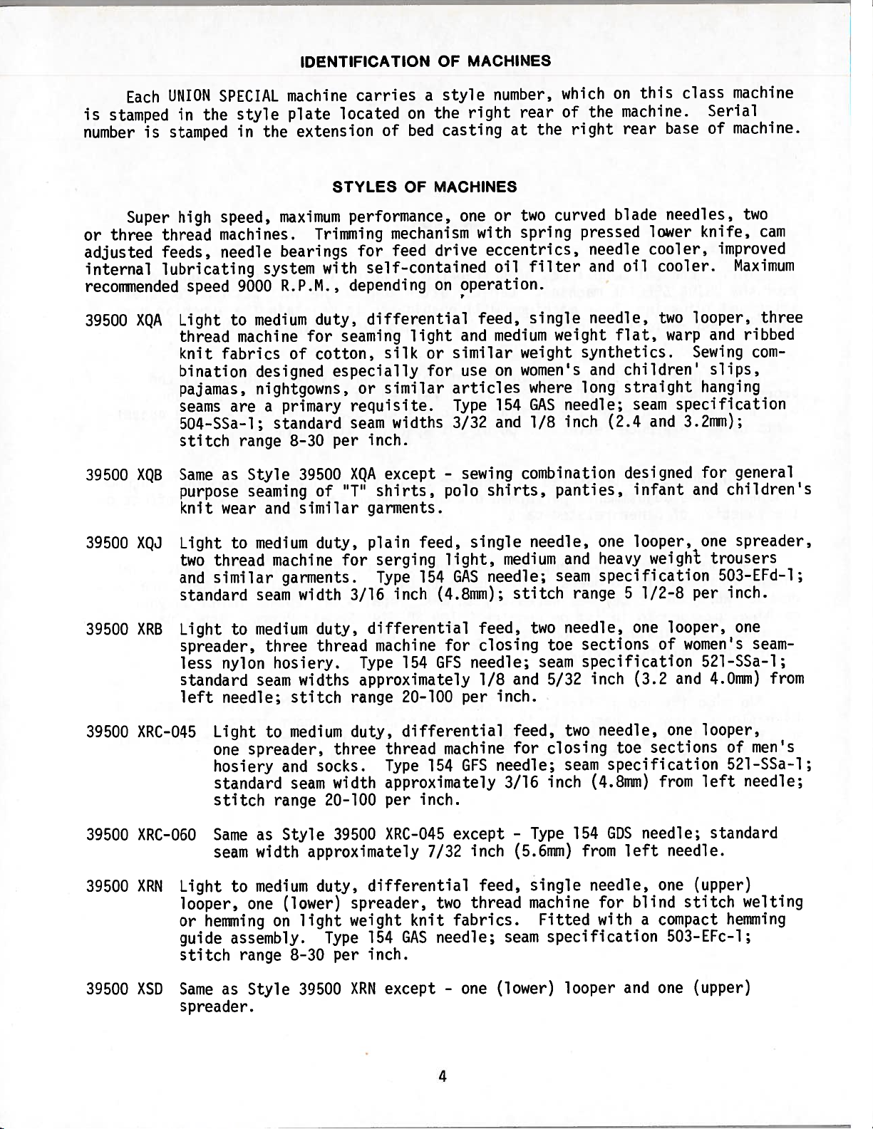
Super
high
speed,
maximum
performance,
one
or
two
curved
blade
needles,
two
or
three
thread
machines.
Trimming
mechanism
with
spring
pressed
lower
knife,
cam
adjusted
feeds,
needle
bearings
for
feed
drive
eccentrics,
needle
cooler,
improved
internal
lubricating
system
with
self-contained
oil
filter
and
oil
cooler.
Maximum
recommended
speed
9000
R.P.M.,
depending
on
operation.
39500
XQA
Light
to
medium
duty,
differential
feed,
single
needle,
two
looper,
three
thread
machine
for
seaming
light
and
medium
weight
flat,
warp
and
ribbed
knit
fabrics
of
cotton,
silk
or
similar
weight
synthetics.
Sewing
com
bination
designed
especially
for
use
on
women’s
and
children’
slips,
pajamas,
nightgowns,
or
similar
articles
where
long
straight
hanging
seams
are
a
primary
requisite.
Type
154
GAS
needle;
seam
specification
504-SSa-l;
standard
seam
widths
3/32
and
1/8
inch
(2.4
and
3.2mm);
stitch
range
8-30
per
inch.
39500
XQB
Same
as
Style
39500
XQA
except
-
sewing
combination
designed
for
general
purpose
seaming
of
“T”
shirts,
polo
shirts,
panties,
infant
and
children’s
knit
wear
and
similar
garments.
39500
XQJ
Light
to
medium
duty,
plain
feed,
single
needle,
one
looper,
one
spreader,
two
thread
machine
for
serging
light,
medium
and
heavy
weight
trousers
and
similar
garments.
Type
154
GAS
needle;
seam
specification
503-EFd—l;
standard
seam
width
3/16
inch
(4.8mm);
stitch
range
5
1/2-8
per
inch.
39500
XRB
Light
to
medium
duty,
differential
feed,
two
needle,
one
looper,
one
spreader,
three
thread
machine
for
closing
toe
sections
of
women’s
seam
less
nylon
hosiery.
Type
154
GFS
needle;
seam
specification
521-SSa-1;
standard
seam
widths
approximately
1/8
and
5/32
inch
(3.2
and
4.0mm)
from
left
needle;
stitch
range
20-100
per
inch.
39500
XRC-045
Light
to
medium
duty,
differential
feed,
two
needle,
one
looper,
one
spreader,
three
thread
machine
for
closing
toe
sections
of
men’s
hosiery
and
socks.
Type
154
GFS
needle;
seam
specification
521-SSa-l;
standard
seam
width
approximately
3/16
inch
(4.8mm)
from
left
needle;
stitch
range
20-100
per
inch.
39500
XRC-060
Same
as
Style
39500
XRC-045
except
-
Type
154
GDS
needle;
standard
seam
width
approximately
7/32
inch
(5.6mm)
from
left
needle.
39500
XRN
Light
to
medium
duty,
differential
feed,
single
needle,
one
(upper)
looper,
one
(lower)
spreader,
two
thread
machine
for
blind
stitch
welting
or
hemming
on
light
weight
knit
fabrics.
Fitted
with
a
compact
hemming
guide
assembly.
Type
154
GAS
needle;
seam
specification
503-EFc-1;
stitch
range
8-30
per
inch.
39500
XSD
Same
as
Style
39500
XRN
except
-
one
(lower)
looper
and
one
(upper)
spreader.
4
From the library of: Superior Sewing Machine & Supply LLC
MACHINE
STYLES
(Continued)
39500
XTA
39500
CXQA
39500
CXQB
39500
CXQJ
39500
CXRN
39500
CXSD
39500
XSQB
39500
CXSQB
Light
duty,
differential
feed,
single
needle,
two
looper,
three
thread
machine
for
toe
closing
on
women’s
seamless
hosiery.
Type
154
GAS
needle;
seam
specification
505-tEe-i;
standard
seam
width
1/16
to
3/32
inch
(1.6
to
2.4mm)
depending
on
material;
stitch
range
15-100
per
inch.
Same
as
Style
39500
XQA
except
-
fitted
with
Power
“AIR-KLIPP”®
chain
cutter.
Same
as
Style
39500
XQB
except
-
fitted
with
Power
“AIR-KLIPP”
chain
cutter.
Same
as
Style
39500
XQJ
except
-
fitted
with
Power
“AIR-KLIPP”
chain
cutter.
Same
as
Style
39500
XRN
except
-
fitted
with
Power
“AIR—KLIPP”
chain
cutter.
Same
as
Style
39500
XSD
except
-
fitted
with
Power
“AIR-KLIPP”
chain
cutter.
Same
as
Style
39500
XQB
except
-
designed
to
use
SHORT,
STIFF
NEEDLE
(Type
162
SAS)
which
reduces
needle
cutting.
Same
as
Style
39500
CXQB
except
-
designed
to
use
SHORT,
STIFF
NEEDLE
(Type
162
SAS)
which
reduces
needle
cutting.
SPEED
RECOMMENDATION
39500
9M
machines
have
been
tested
in
their
complete
stitch
range
at
their
maximum
rated
speeds.
Varied
sewing
applications
may
necessitate
operating
at
a
lower
speed.
When
operating
from
50-100%
machine
running
cycle
and
longer
than
recommended
stitch
length,
it
may
be
necessary
to
reduce
machine’s
speed
by
10-15%.
The
9M
is
a
precision
manufactured
and
tested
sewing
machine,
and
are
run-in
at
the
factory
to
achieve
maximum
speed.
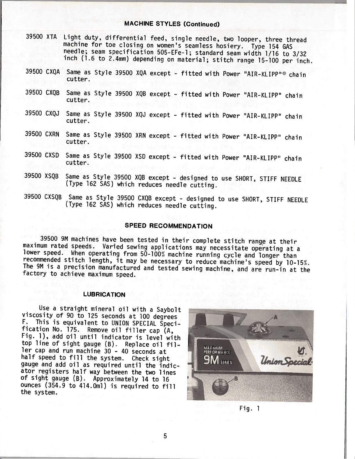
LUBRICATION
Use
a
straight
mineral
oil
with
a
Saybolt
viscosity
of
90
to
125
seconds
at
100
degrees
F.
This
is
equivalent
to
UNION
SPECIAL
Speci
fication
No.
175.
Remove
oil
filler
cap
(A,
Fig.
1),
add
oil
until
indicator
is
level
with
top
line
of
sight
gauge
(B).
Replace
oil
fil
ler
cap
and
run
machine
30
-
40
seconds
at
half
speed
to
fill
the
system.
Check
sight
gauge
and
add
oil
as
required
until
the
indic
ator
registers
half
way
between
the
two
lines
of
sight
gauge
(B).
Approximately
14
to
16
ounces
(354.9
to
414.Oml)
is
required
to
fill
the
system.
Z1aL
Fig.
1
5
From the library of: Superior Sewing Machine & Supply LLC
LUBRICATION
(Continued)
To
maintain
maximum
reconnended
speed
and
servicability
of
this
equipment
when
operating
continously,
the
oil
must
be
changed
at
least
every
six
months.
In
no
case
should
oil
remain
in
the
machine
for
more
than
one
year.
Oil
drain
plug
is
located
at
rear
of
machine
near
bottom
edge
of
base.
ALWAYS
change
oil
filter
whenever
oil
is
changed.
It
is
recommended
to
change
oil
filter
after
the
first
three
months
of
operation
-
or
immediately,
when
oil
is
not
visible
in
the
oil
filler
cap
while
machine
is
running.
NOTE:
An
oil
by-pass
valve
is
incorporated
in
the
lubricating
system
so
if
oil
filter
should
become
clogged
(oil
not
visible
in
filler
cap
while
machine
is
running)
machine
will
automatically
revert
to
the
splash
system,
but
it
is
not
advisable
to
operate
for
an
extended
length
of
time.
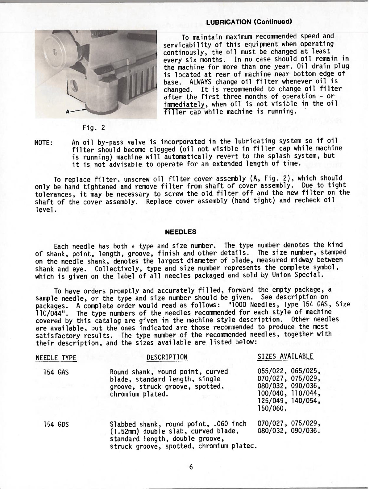
To
replace
filter,
unscrew
oil
filter
cover
assembly
(A,
Fig.
2),
which
should
only
be
hand
tightened
and
remove
filter
from
shaft
of
cover
assembly.
Due
to
tight
tolerances,
it
may
be
necessary
to
screw
the
old
filter
off
and
the
new
filter
on
the
shaft
of
the
cover
assembly.
Replace
cover
assembly
(hand
tight)
and
recheck
oil
level.
NEEDLES
Each
needle
has
both
a
type
and
size
number.
The
type
number
denotes
the
kind
of
shank,
point,
length,
groove,
finish
and
other
details.
The
size
number,
stamped
on
the
needle
shank,
denotes
the
largest
diameter
of
blade,
measured
midway
between
shank
and
eye.
Collectively,
type
and
size
number
represents
the
complete
symbol,
which
is
given
on
the
label
of
all
needles
packaged
and
sold
by
Union
Special.
To
have
orders
promptly
and
accurately
filled,
forward
the
empty
package,
a
sample
needle,
or
the
type
and
size
number
should
be
given.
See
description
on
packages.
A
complete
order
would
read
as
follows:
“1000
Needles,
Type
154
GAS,
Size
110/044”.
The
type
numbers
of
the
needles
recommended
for
each
style
of
machine
covered
by
this
catalog
are
given
in
the
machine
style
description.
Other
needles
are
available,
but
the
ones
indicated
are
those
recommended
to
produce
the
most
satisfactory
results.
The
type
number
of
the
recommended
needles,
together
with
their
description,
and
the
sizes
available
are
listed
below:
NEEDLE
TYPE
DESCRIPTION
SIZES
AVAILABLE
154
GAS
Round
shank,
round
point,
curved
055/022,
065/025,
blade,
standard
length,
single
070/027,
075/029,
groove,
struck
groove,
spotted,
080/032,
090/036,
chromium
plated.
100/040,
110/044,
125/049,
140/054,
150/060.
154
GDS
Slabbed
shank,
round
point,
.060
inch
070/027,
075/029,
(1.52mm)
double
slab,
curved
blade,
080/032,
090/036.
standard
length,
double
groove,
struck
groove,
spotted,
chromium
plated.
Fig.
2
6
From the library of: Superior Sewing Machine & Supply LLC
NEEDLES
(Continued)
NEEDLE
TYPE
DESCRIPTION
SIZES
AVAILABLE
Slabbed
shank,
round
point,
.046
inch
(1.17mm)
double
slab,
curved
blade,
standard
length,
single
groove,
struck
groove,
ball
point,
spotted,
chromium
plated.,
162
SAS
Round
shank,
round
point,
curved
065/025,
blade,
single
groove,
struck
075/029,
groove,
spotted,
chromium
plated.
090/036,
NEEDLE
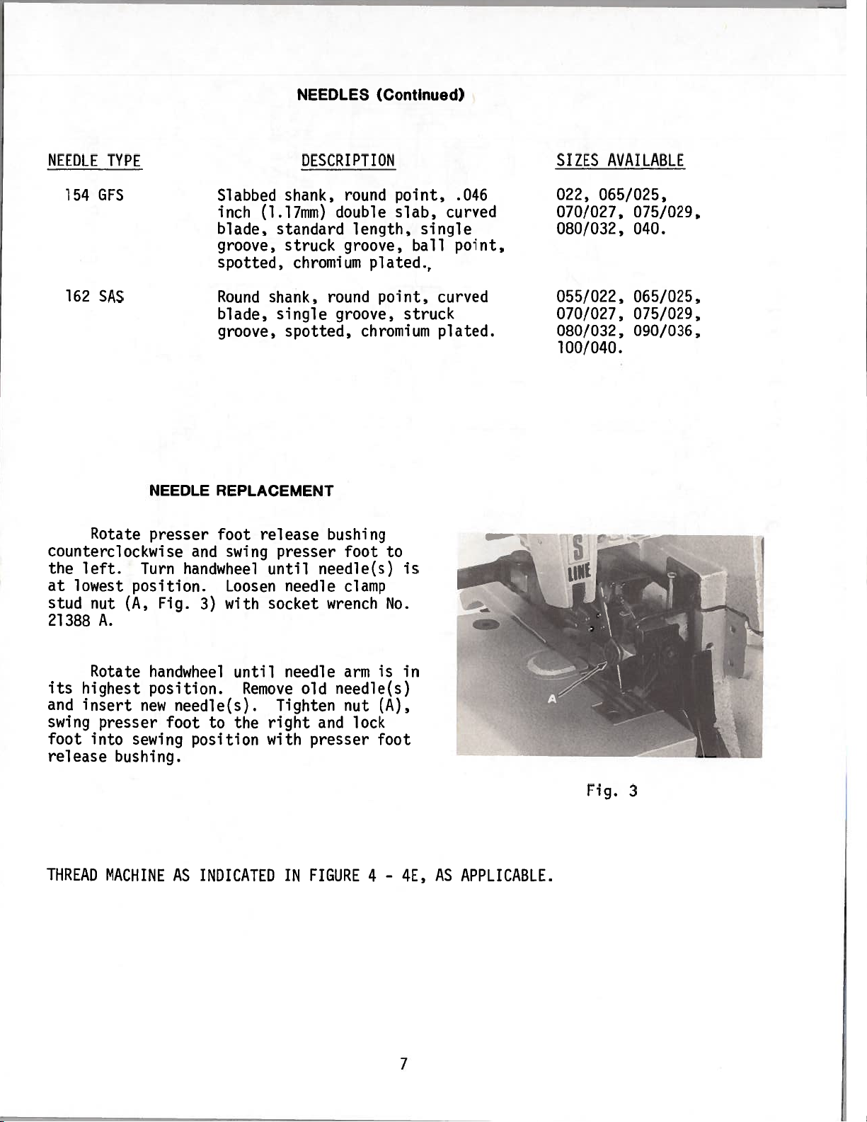
REPLACEMENT
Rotate
presser
foot
release
bushing
counterclockwise
and
swing
presser
foot
to
the
left.
Turn
handwheel
until
needle(s)
is
at
lowest
position.
Loosen
needle
clamp
stud
nut
(A,
Fig.
3)
with
socket
wrench
No.
21388
A.
Rotate
handwheel
until
needle
arm
is
in
its
highest
position.
Remove
old
needle(s)
and
insert
new
needle(s).
Tighten
nut
(A),
swing
presser
foot
to
the
right
and
lock
foot
into
sewing
position
with
presser
foot
release
bushing.
154
GFS
022,
065/025,
070/027,
075/029,
080/032,
040.
055/022,
070/027,
080/032,
100/040.
Fig.
3
THREAD
MACHINE
AS
INDICATED
IN
FIGURE
4
-
4E,
AS
APPLICABLE.
7
From the library of: Superior Sewing Machine & Supply LLC
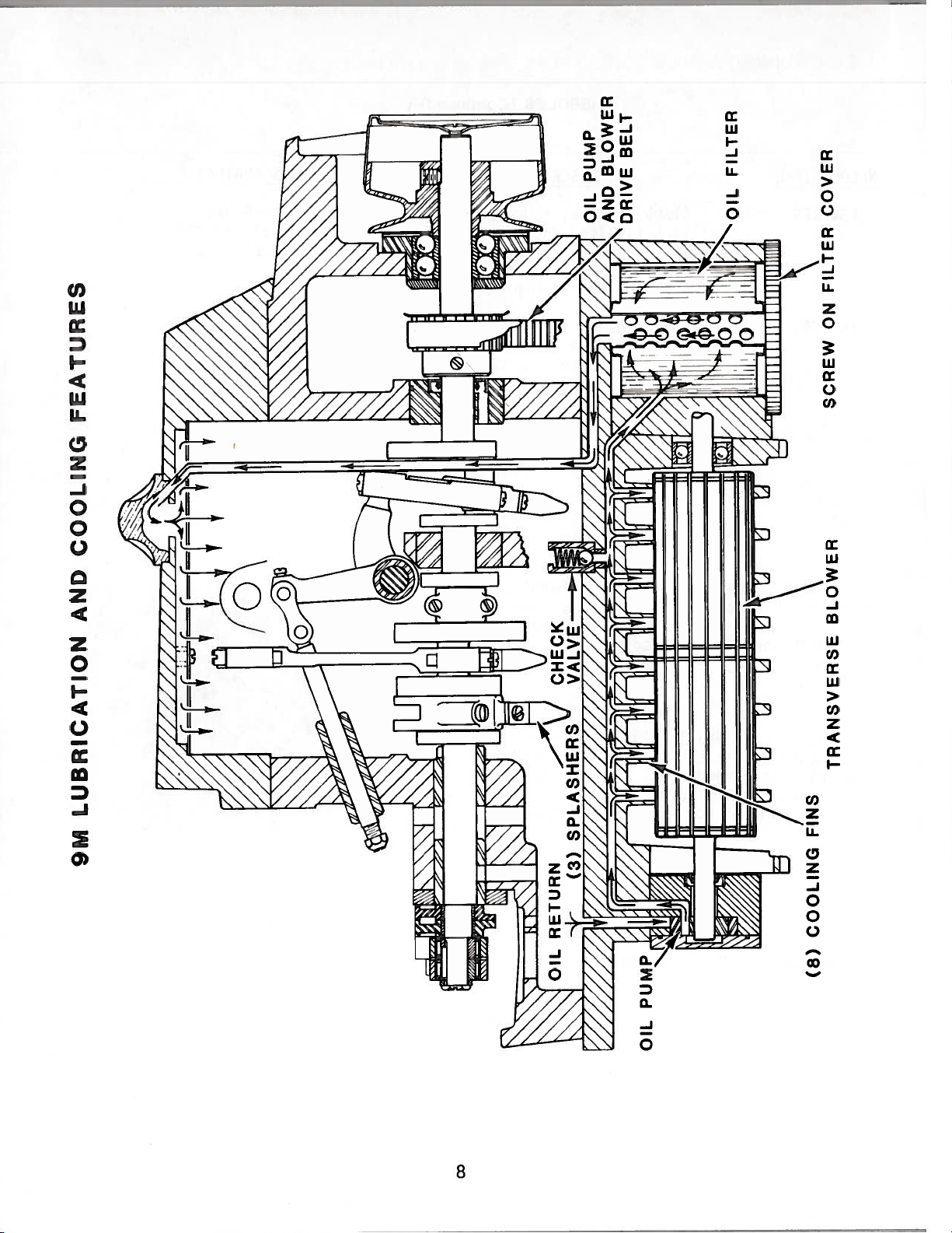
9M
LUBRICATION
AND
COOLING
FEATURES
(8)
COOLING
FINS
OIL
PUMP
AND
BLOWER
DRIVE
BELT
OIL
FILTER
TRANSVERSE
B
SCREW
ON
FILTER
COVER
From the library of: Superior Sewing Machine & Supply LLC
-.
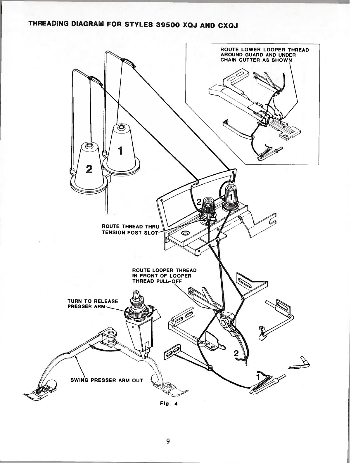
THREADING
DIAGRAM
FOR
STYLES
39500
XOJ
AND
CXOJ
ROUTE
THREAD
TENSION
POST
ROUTE
LOOPER
THREAD
IN
FRONT
OF
LOOPER
THREAD
PULL-OFF
ROUTE
LOWER
LOOPER
THREAD
AROUND
GUARD
AND
UNDER
CHAIN
CUTTER
AS
SHOWN
TURN
TO
RELEASE
PRESSER
SWING
PRESSER
ARM
OUT
Fig.
4
9
From the library of: Superior Sewing Machine & Supply LLC
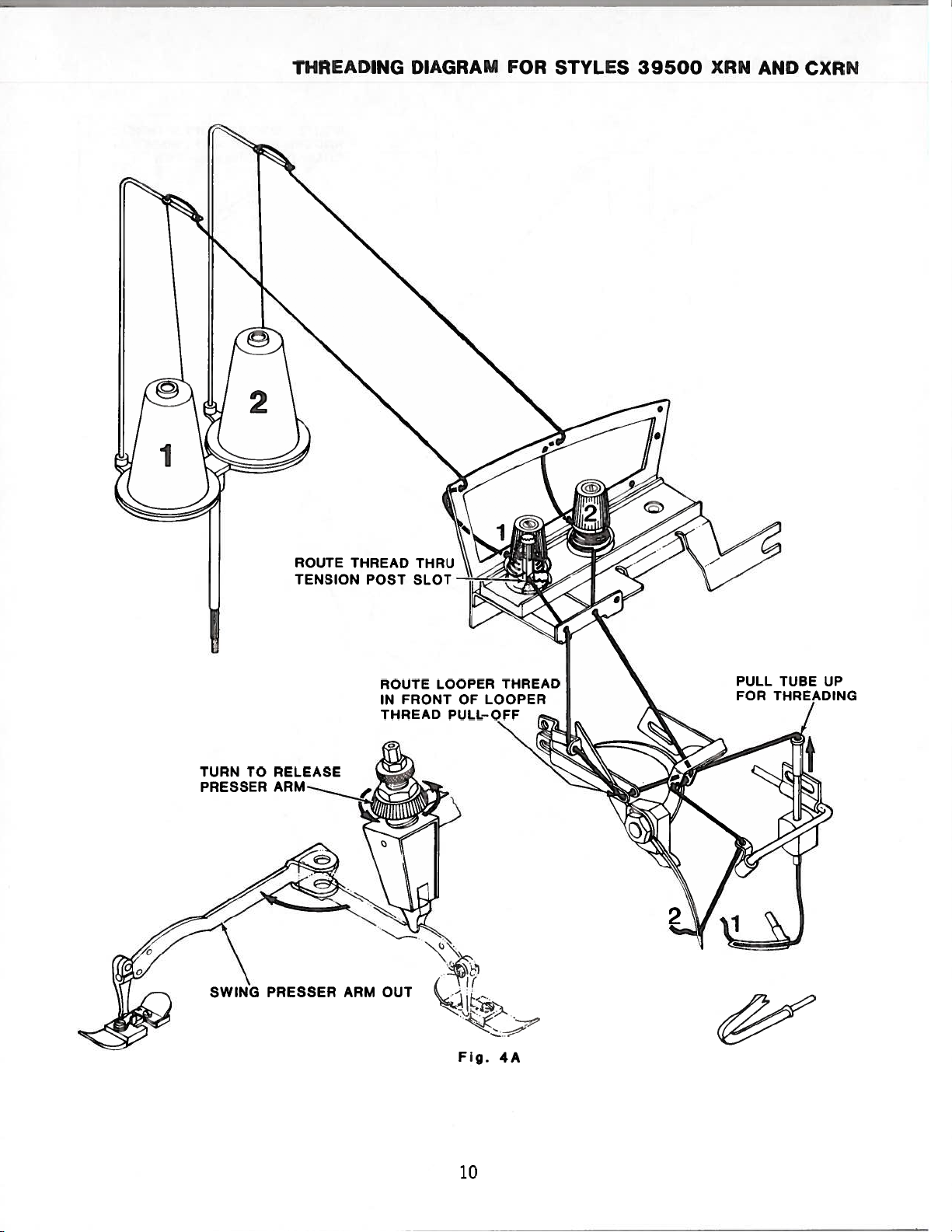
THREADING
DIAGRAM
FOR
STYLES
39500
XRN
AND
CXRN
ROUTE
THREAD
TENSION
POST
SLOT
ROUTE
LOOPER
THREAD
IN
FRONT
OF
LOOPER
THREAD
PULL-OFF
PULL
TUBE
UP
TURN TO
RELEASE
PRESSER
PRESSER
ARM
OUT
Fig.
4A
10
From the library of: Superior Sewing Machine & Supply LLC
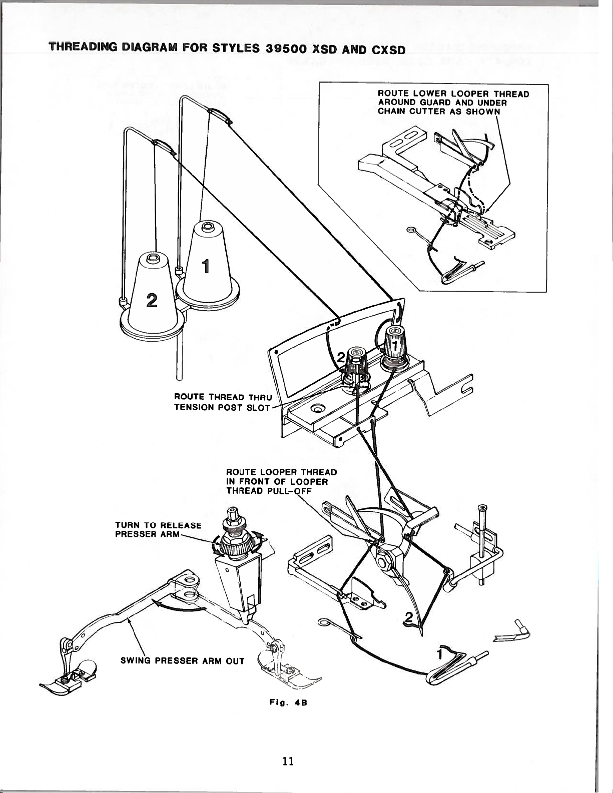
THREADING
DIAGRAM
FOR
STYLES
39500
XSD
AND
CXSD
ROUTE
THREAD
TENSION
POST
SLOT
ROUTE
LOOPER
THREAD
IN
FRONT
OF
LOOPER
THREAD
PULL-OFF
ROUTE
LOWER
LOOPER
THREAD
AROUND
GUARD
AND
UNDER
CHAIN
CUTTER
AS
SHOWN
TURN
TO
RELEASE
PRESSER
PRESSER
ARM
OUT
Fig.
48
11
From the library of: Superior Sewing Machine & Supply LLC
I
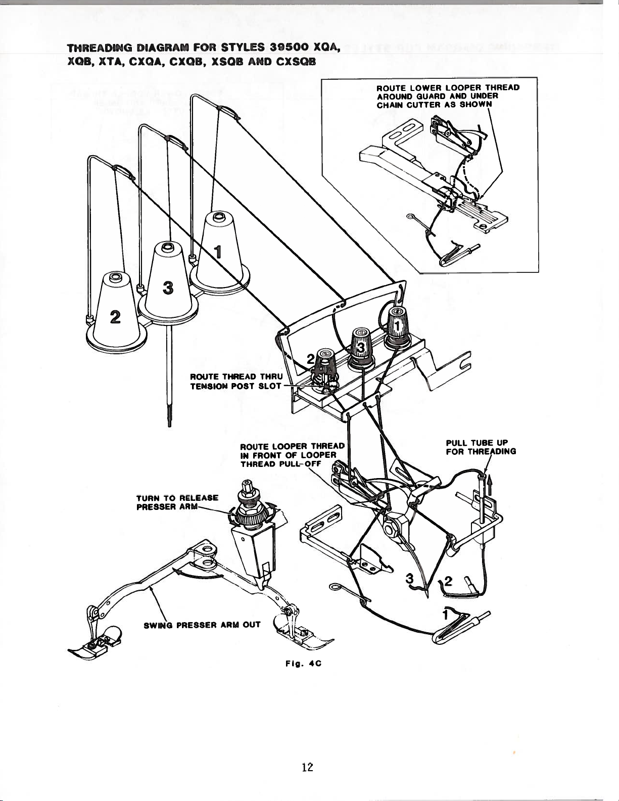
THREADING
DIAGRAM
FOR
STYLES
39500
XQA,
XQB,
XTA,
CXQA,
CXQB,
XSQB
AND
CXSOB
ROUTE
THREAD
TENSION
POST
SLOT
ROUTE
LOOPER
THREAD
IN
FRONT
OF
LOOPER
THREAD
PULL-OFF
TURN
TO
RELEASE
PRESSER
AR
PULL
TUBE
UP
FOR
THREADING
Fig.
4C
12
From the library of: Superior Sewing Machine & Supply LLC
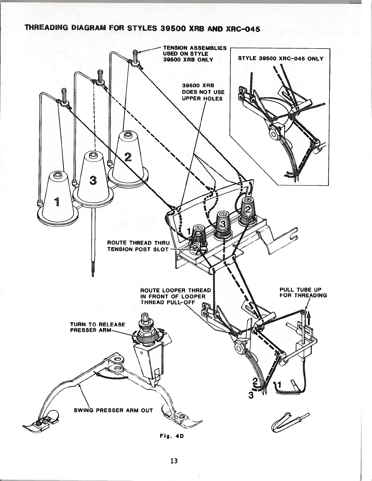
ThREADING
DIAGRAM
FOR
STYLES
39500
XRB
AND
XRC-045
TENSION
ASSEMBLIES
USED
ON
STYLE
39500
XRB
ONLY
39500
XRB
DOES
NOT
USE
UPPER
HOLES
ROUTE
LOOPER
THREAD
IN
FRONT
OF
LOOPER
THREAD
PULL-OFF
STYLE
39500
XRC-045
ONLY
TURN
TO
RELEASE
PRESSER
PRESSER
ARM
OUT
Fig.
40
ROUTE
THREAD
THRU
TENSION
POST
SLOT
UP
13
From the library of: Superior Sewing Machine & Supply LLC
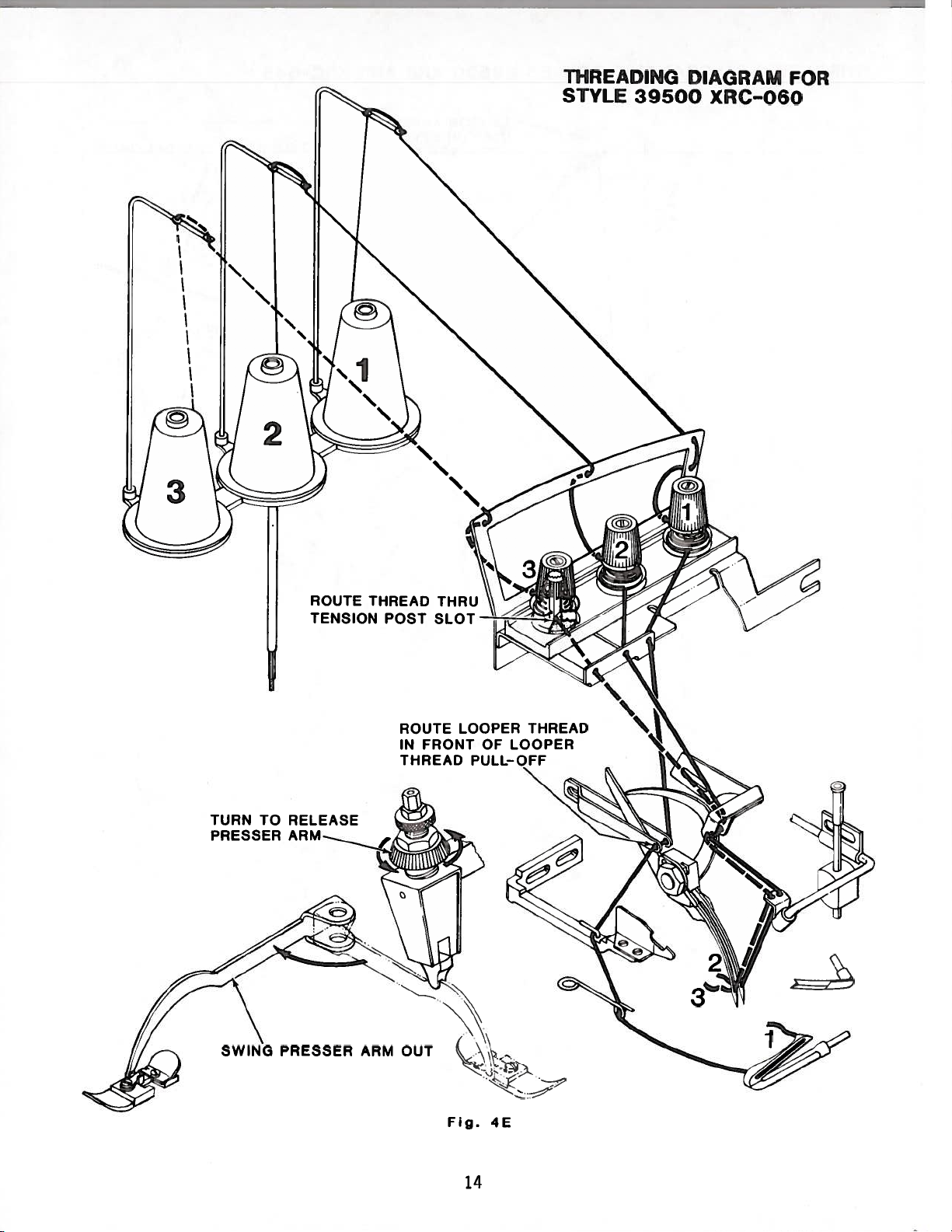
ROUTE
THREAD
TENSION
POST
SLOT
THREADING
DIAGRAM
FOR
STYLE
39500
XRC-060
TURN
TO
RELEASE
PRESSER
ARM
ROUTE
LOOPER
THREAD
IN
FRONT
OF
LOOPER
THREAD
PULL-OFF
SWING
PRESSER
ARM
OUT
Fig.
4E
14
From the library of: Superior Sewing Machine & Supply LLC
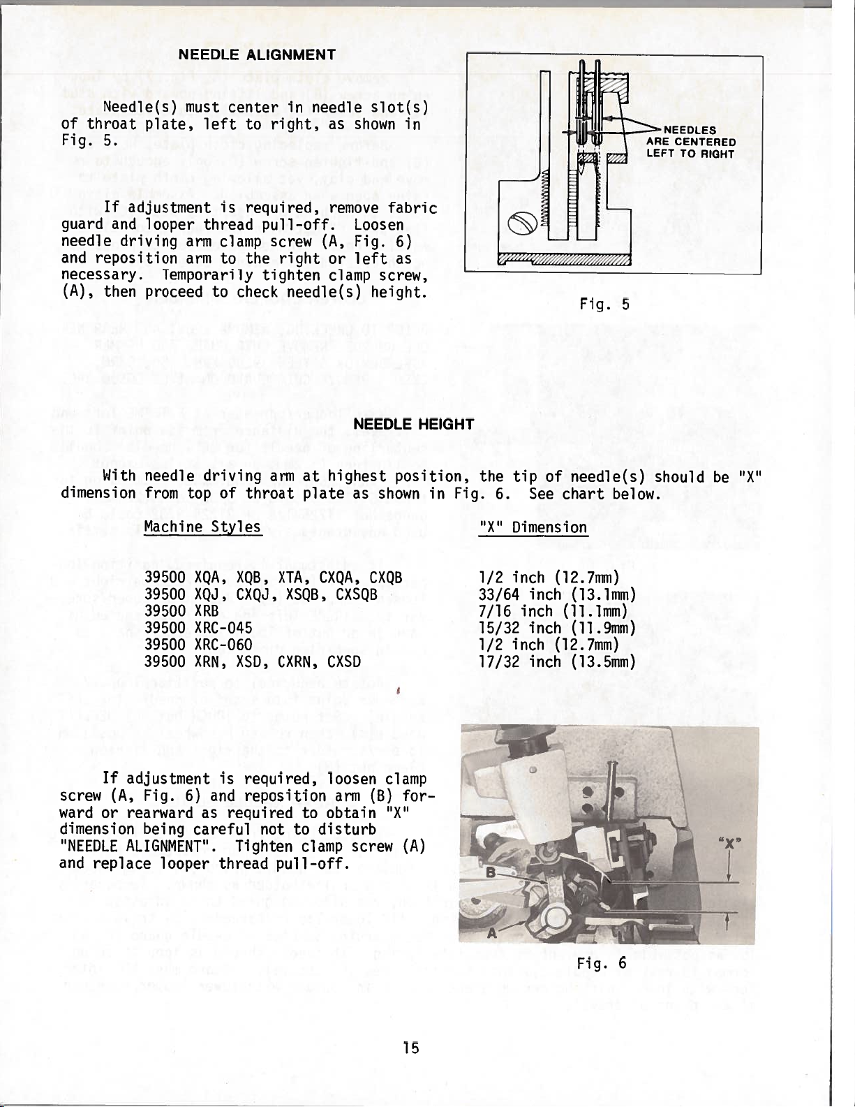
NEEDLE
ALIGNMENT
Needle(s)
must
center
in
needle
slot(s)
of
throat
plate,
left
to
right,
as
shown
in
Fig.
5.
If
adjustment
is
required,
remove
fabric
guard
and
looper
thread
pull-off.
Loosen
needle
driving
arm
clamp
screw
(A,
Fig.
6)
and
reposition
arm
to
the
right
or
left
as
necessary.
Temporarily
tighten
clamp
screw,
(A),
then
proceed
to
check
needle(s)
height.
NEEDLE HEIGHT
With
needle
driving
arm
at
highest
position,
the
tip
of
needle(s)
should
be
“X”
dimension
from
top
of
throat
plate
as
shown
in
Fig.
6.
See
chart
below.
Machine
Styles
“X”
Dimension
XQA,
XQB,
XTA,
CXQA,
CXQB
XQJ,
CXQJ,
XSQB,
CXSQB
X
RB
XRC-045
XRC-060
XRN,
XSD,
CXRN,
CXSD
If
adjustment
is
required,
loosen
clamp
screw
(A,
Fig.
6)
and
reposition
arm
(B)
for—
ward
or
rearward
as
required
to
obtain
“X”
dimension
being
careful
not
to
disturb
“NEEDLE
ALIGNMENT”.
Tighten
clamp
screw
(A)
and
replace
looper
thread
pull-off.
1/2
inch
(12.7mm)
33/64
inch
(13.1mm)
7/16
inch
(11.1mm)
15/32
inch
(11
.9mm)
1/2
inch
(12.7mm)
17/32
inch
(13.5mm)
NEEDLES
ARE
CENTERED
LEFT
TO
RIGHT
Fig.
5
39500
39500
39500
39500
39500
39500
——1
.4
Fig.
6
15
From the library of: Superior Sewing Machine & Supply LLC
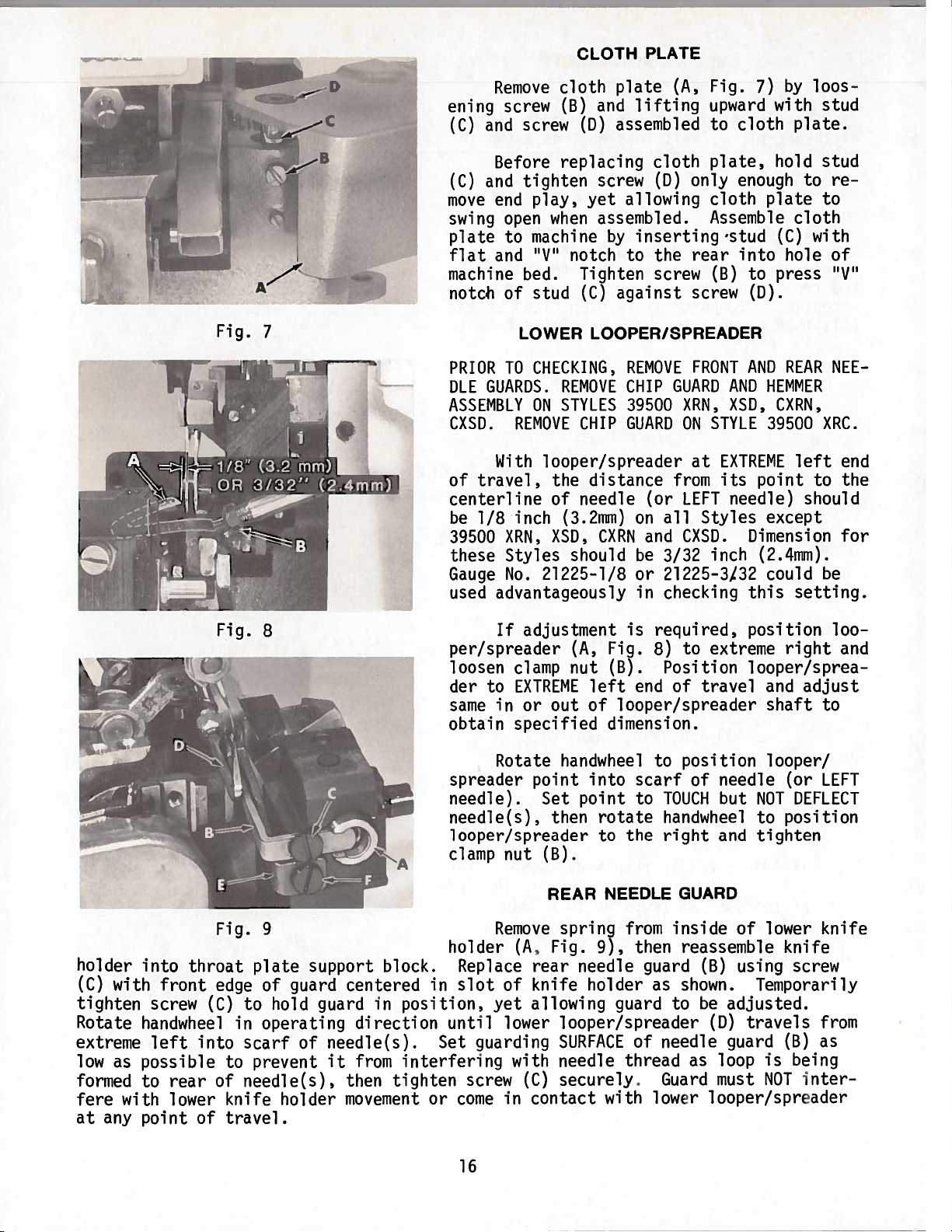
CLOTH
PLATE
Remove
cloth
plate
(A,
Fig.
7)
by
loos
ening
screw
(B)
and
lifting
upward
with
stud
(C)
and
screw
CD)
assembled
to
cloth
plate.
Before
replacing
cloth
plate,
hold
stud
(C)
and
tighten
screw
(D)
only
enough
to
re
move
end
play,
yet
allowing
cloth
plate
to
swing
open
when
assembled.
Assemble
cloth
plate
to
machine
by
inserting
‘stud
(C)
with
flat
and
“V’
notch
to
the
rear
into
hole
of
machine
bed.
Tighten
screw
(B)
to
press
“V’
notch
of stud
(C)
against
screw
(D).
LOWER
LOOPER/SPREADER
PRIOR
TO
CHECKING,
REMOVE
FRONT
AND
REAR
NEE
DLE
GUARDS.
REMOVE
CHIP
GUARD
AND
HEMMER
ASSEMBLY
ON
STYLES
39500
XRN,
XSD,
CXRN,
CXSD.
REMOVE
CHIP
GUARD
ON
STYLE
39500
XRC.
With
looper/spreader
at
EXTREME
left
end
of
travel,
the
distance
from
its
point
to
the
centerline
of
needle
(or
LEFT
needle)
should
be
1/8
inch
(3.2mm)
on
all
Styles
except
39500
XRN,
XSD,
CXRN
and
CXSD.
Dimension
for
these
Styles
should
be
3/32
inch
(2.4mm).
Gauge
No.
21225-1/8
or
21225—3/32
could
be
used
advantageously
in
checking
this
setting.
If
adjustment
is
required,
position
loo
per/spreader
(A,
Fig.
8)
to
extreme
right
and
loosen
clamp
nut
(B).
Position
looper/sprea
der to
EXTREME
left
end
of
travel
and
adjust
same
in
or
out of
looper/spreader
shaft
to
obtain
specified
dimension.
Rotate
handwheel
to
position
looper/
spreader
point
into
scarf
of
needle
(or
LEFT
needle).
Set
point
to
TOUCH
but
NOT
DEFLECT
needle(s),
then
rotate
handwheel
to
position
looper/spreader
to
the
right
and
tighten
clamp
nut
(B).
REAR
NEEDLE
GUARD
Fig.
9
Remove
spring
from
inside
of
lower
knife
holder
(A,
Fig.
9),
then
reassemble
knife
holder
into
throat
plate
support
block.
Replace
rear
needle
guard
(B)
using
screw
(C)
with
front
edge
of
guard
centered
in
slot
of
knife
holder
as
shown.
Temporarily
tighten
screw
(C)
to
hold
guard
in
position,
yet
allowing
guard
to
be
adjusted.
Rotate
handwheel
in
operating
direction
until
lower
looper/spreader
(D)
travels
from
extreme
left
into
scarf
of
needle(s).
Set
guarding
SURFACE
of needle
guard
(B)
as
low
as
possible
to
prevent
it
from
interfering
with
needle
thread
as
loop
is
being
formed
to
rear
of
needle(s),
then
tighten
screw
(C)
securely.
Guard
must
NOT
inter
fere
with
lower
knife
holder
movement
or
come
in
contact
with
lower
looper/spreader
at
any
point
of
travel.
C
B
Fig.
7
Fig.
8
16
From the library of: Superior Sewing Machine & Supply LLC
FRONT
NEEDLE
GUARD
Replace
front
needle
guard
(E,
Fig.
9)
using
screw
(F).
Temporarily
tighten
screw
(F)
to
hold
guard
in
position,
yet
allowing
guard
to
be
adjusted.
Rotate
hand-
wheel
in
operating
direction
until
needle(s)
is
at
lowest
position.
Set guarding
SURFACE
of
needle
guard
CE)
to
needle(s)
with
minimum
clearance
-
approximately
.004
inch
(.10mm)
and
tighten
screw
(F)
securely.
Check
to
ensure
needle(s)
is
NOT
being
pinched
between
front
and
rear
needle
guards.
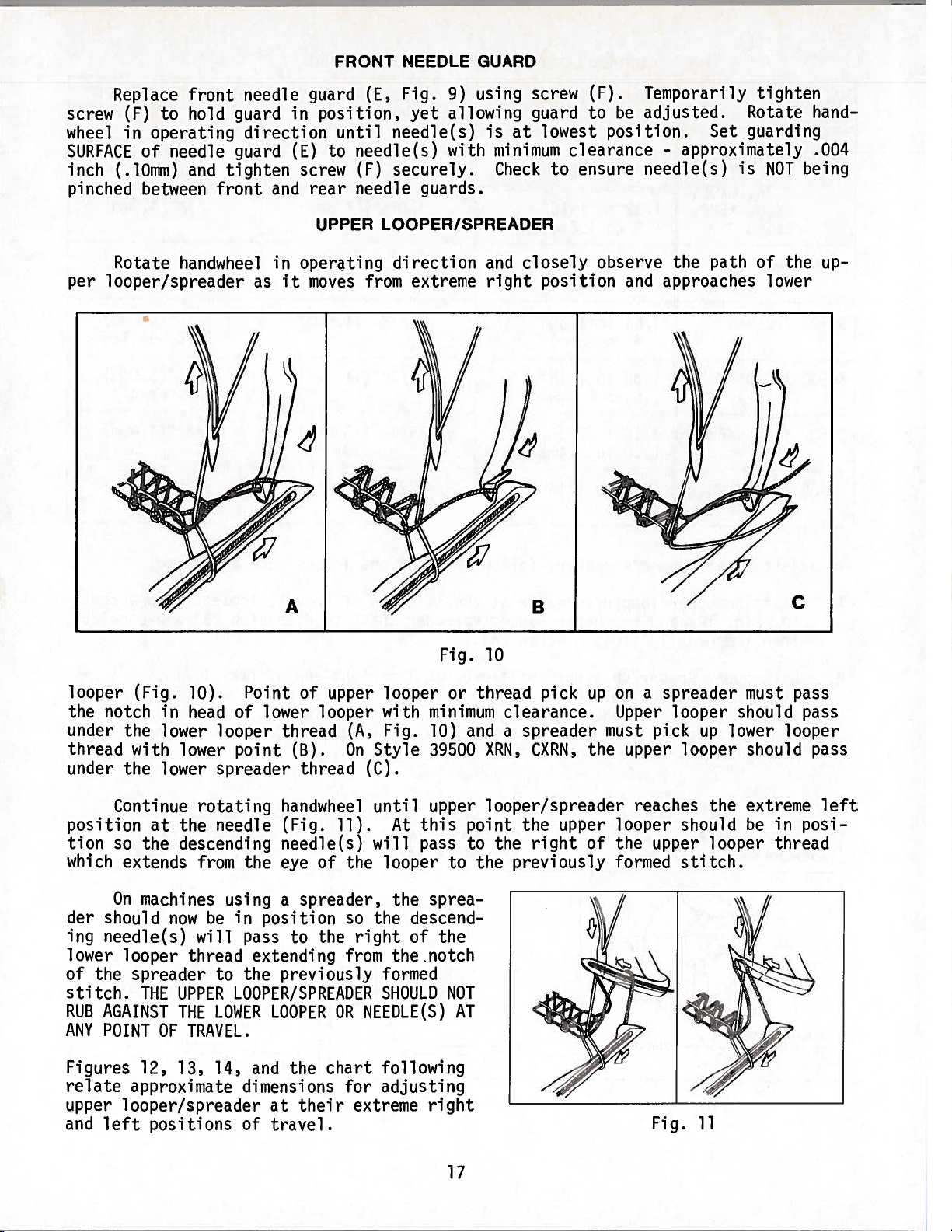
UPPER
LOOPER/SPREADER
Rotate
handwheel
in
operating
direction
and
closely
observe
the
path
of the
up
per
looper/spreader
as
it
moves
from
extreme
right
position
and
approaches
lower
looper
(Fig.
10).
Point
of
upper
looper
or
thread
pick
up
on
a
spreader
must
pass
the
notch
in
head
of
lower
looper
with
minimum
clearance.
Upper
looper
should
pass
under
the
lower
looper
thread
(A,
Fig.
10)
and
a
spreader
must
pick
up
lower
looper
thread
with
lower
point
(B).
On
Style
39500
XRN,
CXRN,
the
upper
looper
should
pass
under
the
lower
spreader
thread
(C).
handwheel
until
upper
looper/spreader
reaches
the
extreme
left
(Fig.
11).
At
this
point
the
upper
looper
should
be
in
posi
needle(s)
will
pass
to
the
right
of
the
upper
looper
thread
eye
of the
looper
to
the
previously
formed
stitch.
On
machines
using
a
spreader,
the
sprea
der
should
now
be
in
position
so
the
descend
ing
needle(s)
will
pass
to
the
right
of
the
lower
looper
thread
extending
from
the.notch
of
the
spreader
to
the
previously
formed
stitch.
THE
UPPER
LOOPER/SPREADER
SHOULD
NOT
RUB
AGAINST
THE
LOWER
LOOPER
OR
NEEDLE(S)
AT
ANY
POINT
OF
TRAVEL.
Figures
12,
13,
14,
and
the
chart
following
relate
approximate
dimensions
for
adjusting
upper
looper/spreader
at
their
extreme
right
and
left
positions
of
travel.
B
C
Fig.
10
Continue
rotating
position
at
the
needle
tion
so
the
descending
which
extends
from
the
Fig.
11
17
From the library of: Superior Sewing Machine & Supply LLC
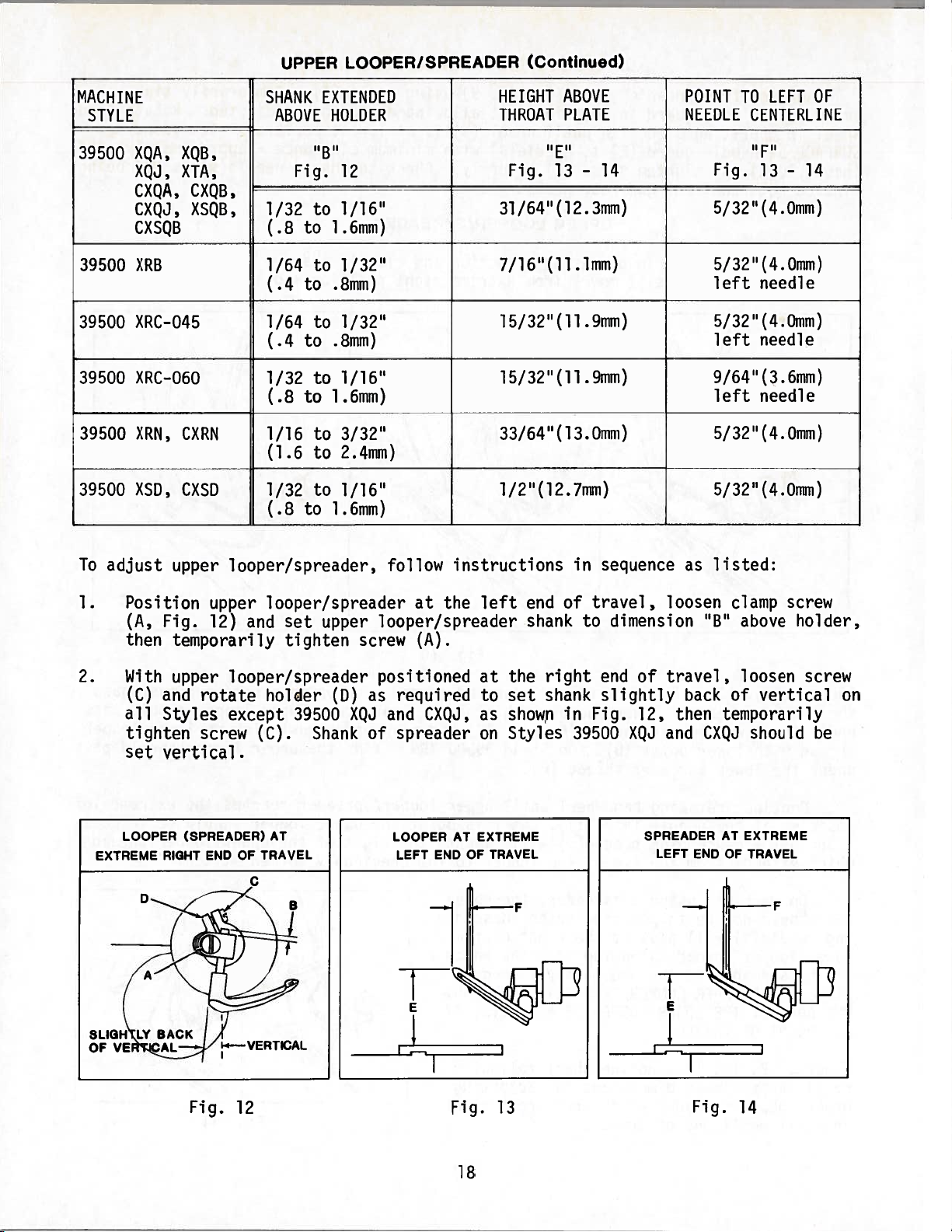
UPPER
LOOPER/SPREADER
(Continued)
MACHINE
SHANK
EXTENDED
HEIGHT
ABOVE
POINT
TO
LEFT
OF
STYLE
ABOVE
HOLDER
THROAT
PLATE
NEEDLE
CENTERLINE
39500
XQA,
XQB,
“B
t
’
“E”
“F”
XQJ,
XTA,
Fig.
12
Fig.
13
-
14
Fig.
13
-
14
CXQA,
CXQB,
CXQJ,
XSQB,
1/32
to
1/16”
31/64(12.3mm)
5/32(4.0mm)
CXSQB
(.8
to
1.6mm)
39500
XRB
1/64
to
1/32”
7/16(11.1mm)
5/32(4.0mm)
(.4
to
.8mm)
left
needle
39500
XRC—O45
1/64
to
1/32”
15/32(11.9mm)
5/32(4.0mm)
(.4
to
.8mm)
left
needle
39500
XRC-06O
1/32
to
1/16”
15/32(11.9mm)
9/64(3.6mm)
(.8
to
1.6mm)
left
needle
39500
XRN,
CXRN
1/16
to
3/32”
33/64(13.0mm)
5/32(4.0mm)
(1.6
to
2.4mm)
39500
XSD,
CXSD
1/32
to
1/16”
l/2”(12.7mm)
5/32(4.0mm)
(.8
to
1.6mm)
To
adjust
upper
looper/spreader,
follow
instructions
in
sequence
as
listed:
1.
Position
upper
looper/spreader
at
the
left
end
of
travel,
loosen
clamp
screw
(A,
Fig.
12)
and
set
upper
looper/spreader
shank
to
dimension
“B”
above
holder,
then
temporarily
tighten
screw
(A).
2.
With
upper
looper/spreader
positioned
(C)
and
rotate
holder
(D)
as
required
all
Styles
except
39500
XQJ
and
CXQJ,
(C).
Shank
of
spreader
tighten
screw
set
vertical.
at
the
right
end
of
travel,
loosen
screw
to
set
shank
slightly
back
of
vertical
on
as
shown
in
Fig.
12,
then
temporarily
on
Styles
39500
XQJ
and
CXQJ
should
be
LOOPER
AT
EXTREME
LEFT
END
OF
TRAVEL
LOOPER
(SPREADER)
AT
EXTREME
RIGHT
END
OF
TRAVEL
C
Fig.
12
Fig.
13
Fig.
14
18
From the library of: Superior Sewing Machine & Supply LLC
 Loading...