


35800DLU
Union Special 35800DLU, 35800DNU, 35800DRU, 35800DRW (NEW), 35800DWW (NEW) Parts List
...
ADJUSTING INSTRUCTIONS / ILLUSTRATED PARTS LIST
REV 01/14/08
35800
High Speed
Feed- Off- The- Arm
With
Plain Feed
Differential Feed
MANUAL NO. PT9804-GR
STYLES
35800DLU
35800DNU
35800DRU
35800DRW
35800DWW
35800PZ
35800DZ

Manual No. PT9804-GR Adjusting Instructions & Illustrated Parts List for
35800 Series Machines
First Edition Copyright 2007
By
Union Special Corporation Rights Reserved In All Countries
Printed in U.S.A. August 2007
PREFACE
This parts manual has been prepared to assist you in locating individual parts or assemblies on 35800 Series machines.
It is the desire of Union Special that each machine run at its optimum performance. Parts listed in this manual are designed
specifically for your machine and are manufactured with utmost precision to assure long lasting service.
This manual has been comprised on the basis of available information. Changes in design and/or improvements may
incorporate a slight modification of configuration in illustrations or part numbers.
On the following pages are illustrations and terminology used in describing the parts used on 35800 Series machines.
DENTIFICATION OF MACHINES
Each UNION SPECIAL machine is identified by a style number, which is stamped into the style plate affixed to the middle of the
machine under the tension assembly.
The serial number is stamped on a plate attached to the right rear top of the machine.
2

CONTENTS
IDENTIFICATION OF MACHINES ............................................................................................................................................................................. 2
SAFETY RULES .......................................................................................................................................................................................................... 4
CLASS DESCRIPTION ............................................................................................................................................................................................. 5
STYLE OF MACHINES .............................................................................................................................................................................................. 5
ILLUSTRATIONS ........................................................................................................................................................................................................ 6
IDENTIFYING PARTS ................................................................................................................................................................................................. 6
NEEDLES .................................................................................................................................................................................................................. 6
TERMS ...................................................................................................................................................................................................................... 6
THREADING & OILING FOR PLAIN FEED ............................................................................................................................................................... 7
THREADING & OILING FOR DIFFERENTIAL FEED ................................................................................................................................................... 8
NEEDLES .................................................................................................................................................................................................................. 9
LUBRICATION .......................................................................................................................................................................................................... 9
THREADING ............................................................................................................................................................................................................. 9
ADJUSTING INSTRUCTIONS .................................................................................................................................................................................... 9
TORQUE REQUIREMENTS ...................................................................................................................................................................................... 10
SYNCHRONIZING NEEDLE AND LOOPER MOTIONS .......................................................................................................................................... 10
TIGHTENING NEEDLE HEAD ................................................................................................................................................................................. 11
ALIGNING NEEDLES IN THROAT PLATE SLOTS .................................................................................................................................................... 11
CENTERING THE CYLINDER .................................................................................................................................................................................. 11
SETTING THE LOOPER ........................................................................................................................................................................................... 11
SETTING THE LOOPER (CONT.) ............................................................................................................................................................................ 12
SETTING HEIGHT OF NEEDLE BAR ........................................................................................................................................................................ 12
SETTING THE FEED DOGS FOR PLAIN FEED ......................................................................................................................................................... 12
SETTING THE FEED DOGS FOR DIFFERENTIAL FEED ............................................................................................................................................. 12
SETTING THE FEED DOGS FOR DIFFERENTIAL FEED (CONT.) .............................................................................................................................. 13
CHANGING STITCH LENGTH ................................................................................................................................................................................ 13
SETTING REAR NEEDLE GUARD ............................................................................................................................................................................ 13
PRESSER FOOT AND PRESSER BAR ADJUSTMENT ............................................................................................................................................... 14
UPPER FEED ROLLER ADJUSTMENT ...................................................................................................................................................................... 14
UPPER FEED ROLLER ADJUSTMENT (CONT.) ....................................................................................................................................................... 15
THREAD TENSION AND RELEASE .......................................................................................................................................................................... 15
DIFFERENTIAL CONTROL ...................................................................................................................................................................................... 15
SETTING NEEDLE THREAD TAKE-UP AND FRAME EYELET .................................................................................................................................... 16
LOOPER THREAD TAKE-UP ADJUSTMENT ............................................................................................................................................................ 16
FOLDER ADJUSTMENT .......................................................................................................................................................................................... 17
AIR BLOWER TUBE ADJUSTMENT .......................................................................................................................................................................... 17
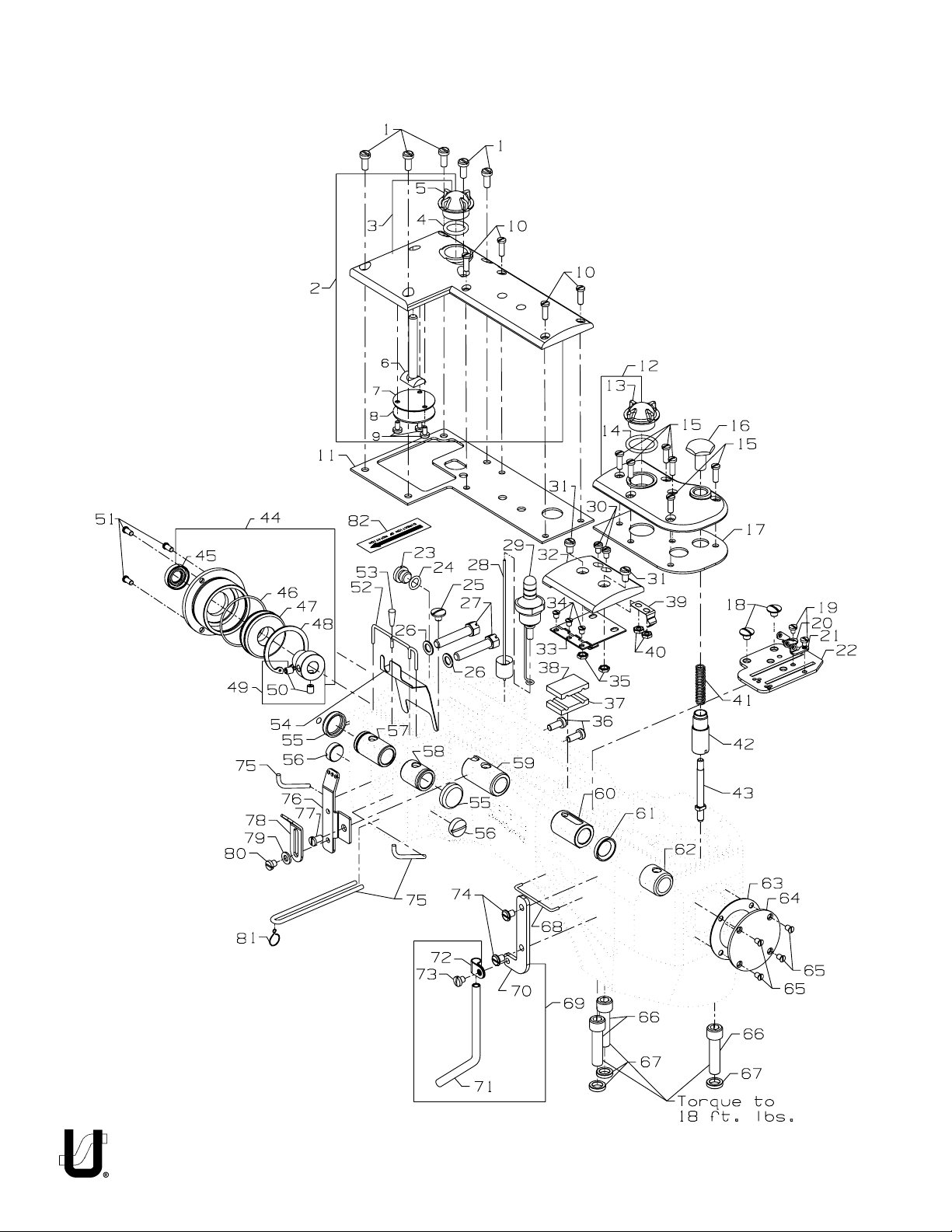
MAIN FRAME, CAST-OFF PLATE, EYELETS, MISCELLANEOUS COVERS AND BUSHINGS ................................................................................. 19
MAIN FRAME, CAST-OFF PLATE, EYELETS, MISCELLANEOUS COVERS AND BUSHINGS (CONT.) ................................................................... 21
CYLINDER COVERS AND BUSHINGS FOR PLAIN FEED ....................................................................................................................................... 23
CYLINDER COVERS AND BUSHINGS FOR PLAIN FEED (CONT.) ........................................................................................................................ 25
CYLINDER COVERS AND BUSHINGS FOR DIFFERENTIAL FEED .......................................................................................................................... 27
CYLINDER COVERS AND BUSHINGS FOR DIFFERENTIAL FEED (CONT.) ........................................................................................................... 29
DETACHABLE HEAD ASSEMBLY ........................................................................................................................................................................... 31
OILING, NEEDLE LEVER, CRANKSHAFT AND MAIN SHAFT PARTS ..................................................................................................................... 33
PLAIN FEED BAR, FEED LIFT & FEED DRIVE COMPONENTS FOR PLAIN FEED .................................................................................................... 35
DIFFERENTIAL FEED BAR, MAIN FEED BAR, FEED LIFT ECCENTRIC ASSEMBLY FOR DIFFERENTIAL FEED ......................................................... 37
FEED DRIVE COMPONENTS, LOOPER DRIVE COMPONENTS AND LOOPERS FOR PLAIN FEED ..................................................................... 39
LOOPERS, LOOPER HOLDERS, FEED DRIVE COMPONENTS AND LOOPER AVOID COMPONENTS FOR DIFFERENTIAL FEED ..................... 41
LOOPERS, LOOPER HOLDERS, FEED DRIVE COMPONENT AND LOOPER AVOID COMPONENT FOR DIFFERENTIAL FEED (CONT.) .......... 43
UPPER ROLLER FEED, FOOT LIFTER AND THREAD TENSION PARTS .................................................................................................................. 45
UPPER ROLLER FEED, FOOT LIFTER AND THREAD TENSION PARTS (CONT.) .................................................................................................... 47
PULLEY, CRANKSHAFT, CLUTCH AND CLUTCH DRIVING MECHANISM ........................................................................................................... 49
PULLEY, CRANKSHAFT, CLUTCH AND CLUTCH DRIVING MECHANISM (CONT.) ............................................................................................ 51
SEWING PARTS ...................................................................................................................................................................................................... 53
THREAD STAND ..................................................................................................................................................................................................... 55
ACCESSORIES ....................................................................................................................................................................................................... 56
NUMERICAL INDEX OF PARTS .............................................................................................................................................................................. 57
NUMERICAL INDEX OF PARTS .............................................................................................................................................................................. 58
NUMERICAL INDEX OF PARTS .............................................................................................................................................................................. 59
NOTES .................................................................................................................................................................................................................... 60
NOTES .................................................................................................................................................................................................................... 61
3

SAFETY RULES
1. Before putting the machines described in this manual into service, carefully read the instructions. The
starting of each machine is only permitted after taking notice of the instructions and by qualified
operators.
IMPORTANT! Before putting the machine into service, also read the safety rules and instructions from the
motor supplier.
2. Observe the national safety rules valid for your country.
3. The sewing machines described in this instruction manual are prohibited from being put into service until
it has been ascertained that the sewing units which these sewing machines will be built into, have
conformed with the EC Council Directives (89/392/EEC, Annex II B).
Each machine is only allowed to be used as foreseen. The foreseen use of the particular machine is
described in paragraph “STYLES OF MACHINES” of this instruction manual. Another use, going beyond
the description, is not as foreseen.
4. All safety devices must be in position when the machine is ready for work or in operation. Operation
of the machine without the appertaining safety devices is prohibited.
5. Wear safety glasses.
6. In case of machine conversions and changes all valid safety rules must be considered. Conversions
and changes are made at your own risk.
7. The warning hints in the instructions are marked with one of these two symbols:
8. When doing the following the machine has to be disconnected from the power supply by turning off
the main switch or by pulling out the main plug:
8.1 When threading needle(s), looper, spreader etc.
8.2 When replacing any parts such as needle(s), presser foot, throat plate, looper, spreader, feed
dog, needle guard, folder, fabric guide etc.
8.3 When leaving the workplace and when the workplace is unattended.
8.4 When doing maintenance work.
8.5 When using clutch motors without actuation lock, wait until the motor is stopped totally.
9. Maintenance, repair and conversion work (see item 8) must be done only by trained technicians or
special skilled personnel under consideration of the instructions.
10. Any work on the electrical equipment must be done by an electrician or under direction and supervision
of special skilled personnel.
11. Work on parts and equipment under electrical power is not permitted. Permissible exceptions are
described in the applicable sections of standard sheet DIN VDE 0105.
12. Before doing maintenance and repair work on the pneumatic equipment, the machine has to be
disconnected from the compressed air supply. In case of existing residual air pressure, after disconnecting from compressed air supply (i.e. pneumatic equipment with air tank), the pressure has to be
removed by bleeding.
4

ICLASS DESCRIPTION
High Speed, Feed-Off-The-Arm High Throw Machines, Two and Three Needle, Left Needle In Front. Light Weight Presser Bar
Mechanism, Adjustable Looper Avoid, Space in Front of Needles 8" (203.2 mm), Single Disc Looper Thread Take-Up, Automatic
Enclosed Type Oiling System and Filter Type Oil Pump, Visual Sight Oil Action and Supply Gauges.
STYLE OF MACHINES
35800DLU DOUBLE LAP SEAM. Three needle, medium capacity, differential feed with upper driven roller feed.
-Typical Application- For in and out seaming on medium weight khaki garments. Seam Specification
401 LSc-3. Standard gauge Number 9 [9/64", 3.6mm]. Recommended needle 130GS, size 110/044.
Maximum recommended speed 4000 R.P.M.. .040 step sewing parts. .468 (15/32, 11.9mm) narrow
rubber roller.
35800DNU DOUBLE LAP SEAM. Three needle, high capacity, differential feed with upper driven roller feed. -Typical
Application- For in and out seaming on heavy weight denim garments. Seam Specification 401 LSc-
3. Standard gauge Numbers 8 [1/8", 3.2mm] and 9 [9/64", 3.6mm]. Recommended needle 130GS,
size 140/054. Maximum recommended speed 4500 R.P.M.. .094 step sewing parts. .468 (15/32,
11.9mm) narrow roller.
35800DZ Same as 35800DNU except with reverse teeth roller.
35800DRU DOUBLE LAP SEAM. Three needle, high capacity, plain feed, upper driven, roller feed. Feed Dogs have
higher teeth on front. - Typical Application- For seat seaming, in and out seams on medium to heavy
weight denim garments. Seam Specifications 401LSc-3. Standard gauge Numbers 8 [1/8", 3.2mm]
and 9 [9/64", 3.6mm]. Recommended needle 130GS, size 140/054. Maximum recommended speed
4500 R.P.M.. .094 step sewing parts. .468 (15/32", 11.9mm) narrow roller.
35800PZ Same as 35800DRU except with reverse teeth roller.
35800DRW DOUBLE LAP SEAM. Three needle, high capacity, plain feed, upper driven, roller feed (wide roller).
Feeds have higher teeth on front of feeds. - Typical Application- For seat seaming, in and out seams
on medium to heavy weight denim garments. Seam Specifications 401LSc-3. Standard gauge 9 [9/
64", 3.6mm]. Recommended needle 130GS, size 140/054. Maximum recommended speed 4500
R.P.M.. .094 step sewing parts. .588" (19/32", 15mm) wide roller.
35800DWW DOUBLE LAP SEAM. Three needle, high capacity, differential feed, high lift feed eccentric, with upper
driven, roller feed (wide roller). Feeds have higher teeth on front of feeds. - Typical Application- For
use on heavy weight denim garments. Seam Specifications 401LSc-3. Standard gauge Numbers 8
[1/8", 3.2mm] and 9 [9/64", 3.6mm]. Recommended needle 130GS, size 140/054. Maximum
recommended speed 4500 R.P.M.. .094 step sewing parts. .588" (19/32", 15mm) wide roller.
5

ILLUSTRATIONS
This manual has been arranged to simplify ordering repair parts. Exploded views of various sections of the mechanism are shown
so that the parts may be seen in their actual position in the machine. On the page opposite the illustration will be found a listing
of the parts with their part numbers, description and the number of pieces required in the particular view being shown.
Numbers in the first column are reference numbers only, and merely indicate the position of the part in the illustration. The reference
number should never be used in ordering parts. Always use the part number listed in the second column.
Component parts of sub-assemblies which can be furnished for repairs are indicated by indenting their descriptions under the
description of the main sub-assembly. As an example refer to the following text.
9. 29126 EC Upper Looper Drive Shaft Assembly ................................................................................ 1
10. 22503 F Screw ............................................................................................................................... 1
11. 39543 E Cam Follower Locking Clamp .......................................................................................... 1
It will be noted in the previous example that the cam follower, bushing and cam guide and the upper looper drive shaft are not
listed. The reason is that replacement of these parts individually is not recommended, so the complete
upper looper drive shaft assembly should be ordered.
When a part is common to all machines covered in this manual, no specific usage will be mentioned in the description. However,
when the parts for the various machines are not the same, the specific usage will be mentioned in the description and, if necessary,
the difference will be shown in the illustration.
A numerical index of all the parts shown in this manual is located at the back. This will facilitate locating the illustration and
description when only a part number is known.
IDENTIFYING PARTS
Where the construction permits, each part is marked with its part number. On some of the smaller parts and on those where
construction does not permit, an identification letter is marked in to distinguish the part from similar ones.
PLEASE NOTE: Part numbers represent the same part, regardless of which manual they appear. On all orders please
include part number, name and style of machine for which the part was ordered.
NEEDLES
Each needle has both a type and size number. The type number denotes the kind of shank, point, length, groove, finish
and other details. The size number, stamped on the needle shank, denotes the largest diameter of the blade measured
between the shank and the eye. Collectively, the type number and size number represent the complete symbol which
is given on the label of all needles packed and sold by Union Special.
TYPE DESCRIPTION
130 GS Short, double groove, struck groove, ball eye, spotted, government point, chromium plated- Sizes available
080/032, 090/036, 100/040, 110/044, 125/049, 140/054, 150/060.
To have needles promptly and accurately filled, an empty package, a needle sample, or the type and size
number should be forwarded. Use the description on the label. A complete order should read as follows:
"100 needles, type 130 GS, size 125/049".
TERMS
Prices are net cash and subject to change without notice. All shipments are forwarded F.O.B. shipping point.
A charge is made to cover postage and insurance.
6
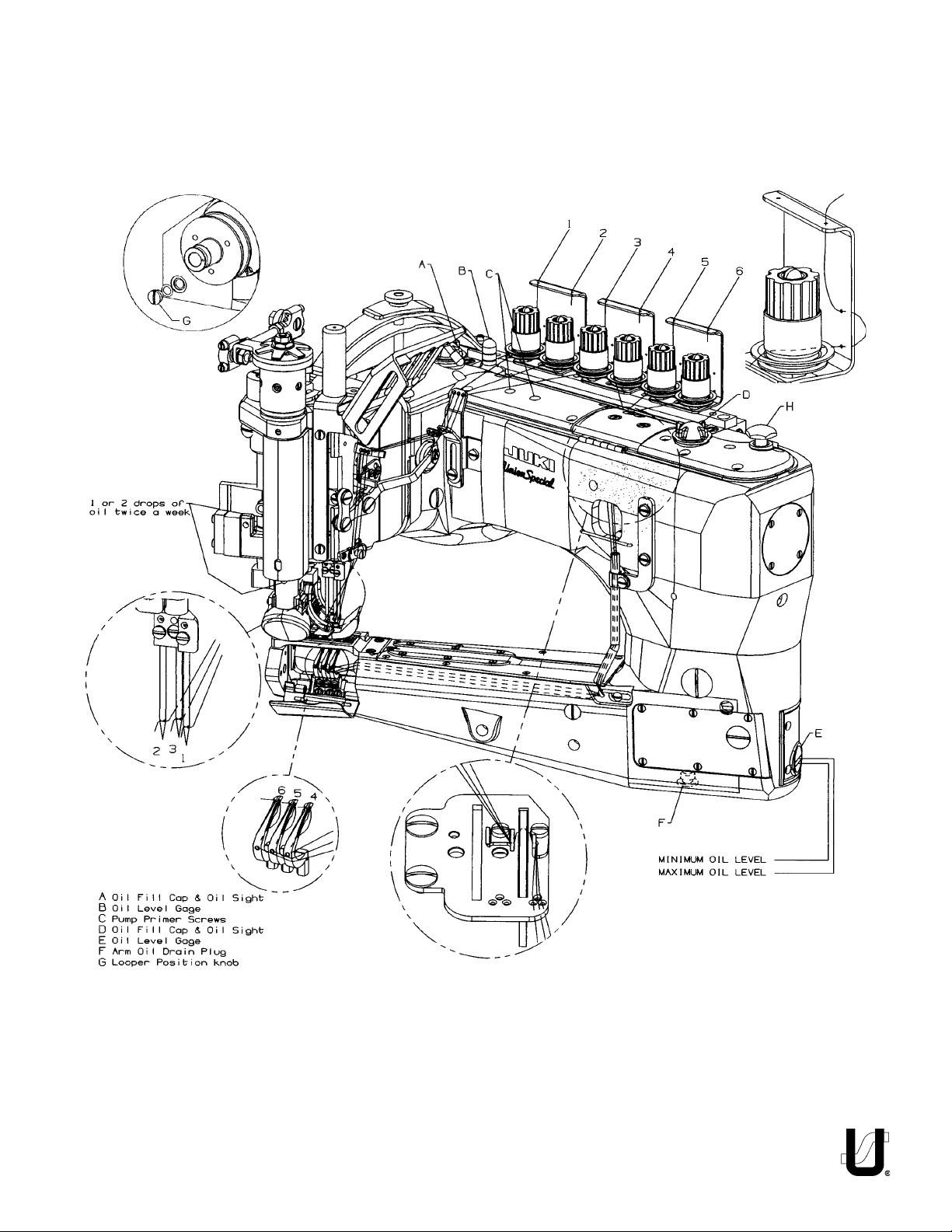
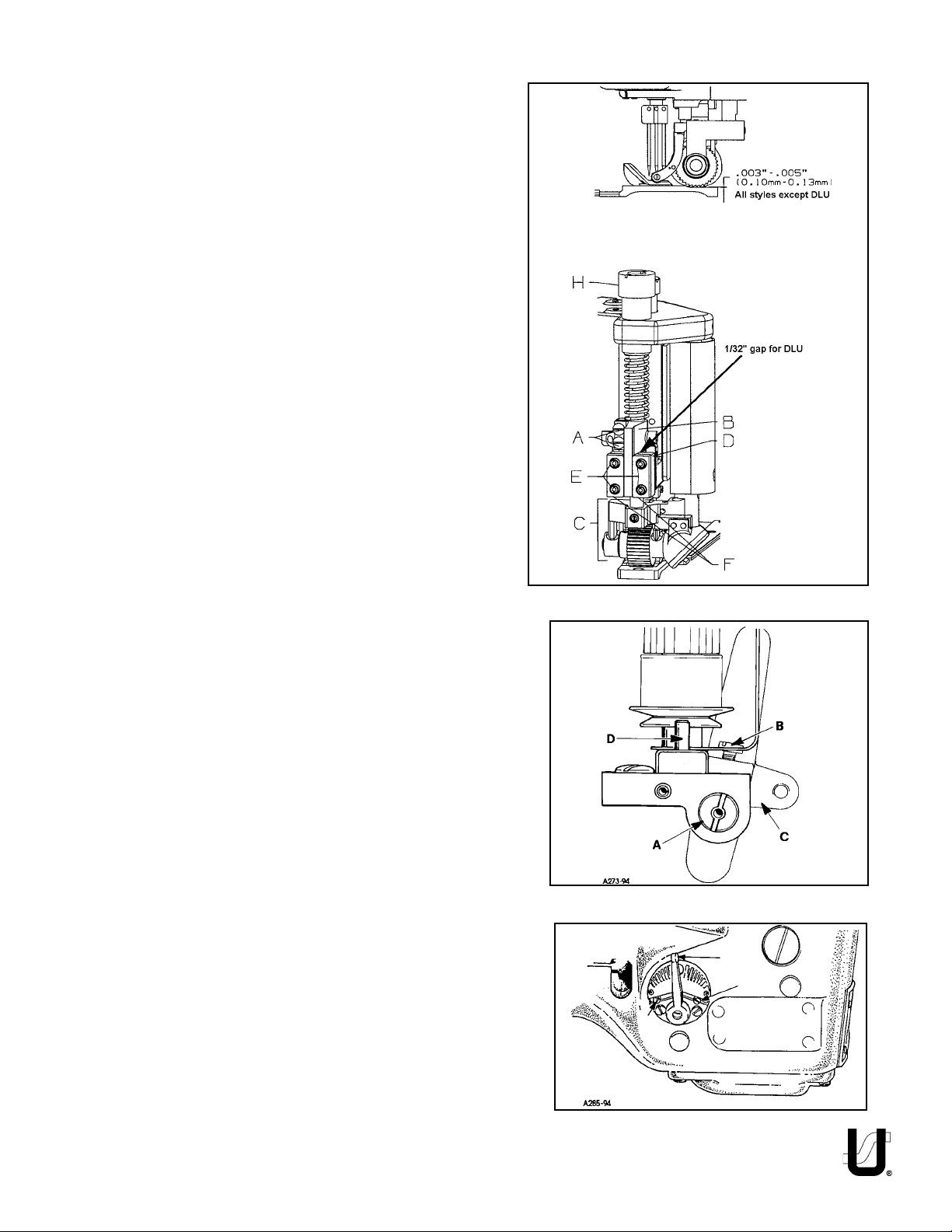
THREADING & OILING FOR PLAIN FEED
FIG. 1A
7
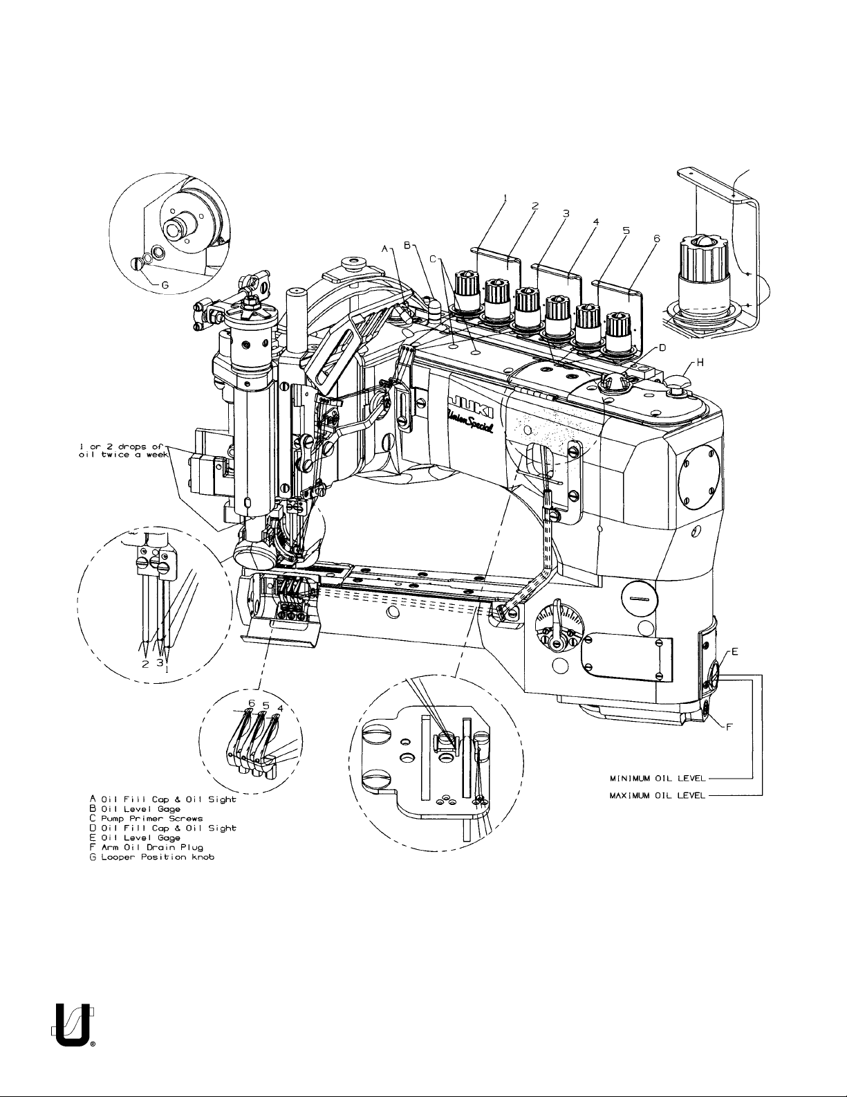
THREADING & OILING FOR DIFFERENTIAL FEED
FIG. 1B
8

epyTeldeeNnoitpircseDelbaliavAseziS
SG031
tnioptnemnrevog
.detalpmuimorhc,
,dettops,eyellab,evoorgkcurts,evoorgelbuodtrohS
060/051,450/041
,940/521,440/011,040/001,630/090,230/080
Table 1
NEEDLES
Selection of proper needle size is determined by size of thread used. Thread should pass freely through the needle eye in
order to produce a good stitch formation.
Each needle has both a type and size number. The type number denotes the kind of shank, point, length, groove, finish
and other details. The size number, stamped on the needle shank, denotes largest diameter of blade, measured midway
between shank and eye. Collectively, type and size number represent the complete symbol which is given on the label
of all needles packaged and sold by UNION SPECIAL. See "STYLE OF MACHINES" for the standard recommended needle
type & size for your machine.
To have needle orders promptly and accurately filled, an empty package, a sample needle, or the type and size number
should be forwarded. Use the description on the label. A complete order would read: “1000 Needles, Type 130GS, Size 140/
054”.
LUBRICATION
The oil has been drained from the machine before shipping and the reservoirs must be filled before beginning to operate.
Use a straight mineral oil with a Saybolt viscosity of 90 to 125 seconds at 100° Fahrenheit. Union Special Part No. 28604R.
Oil is filled at oil caps (A & D, Fig. 1A, B). The level is checked at sight gauges (B) and (E). Maintain the oil level between the
red lines of the gauges.
The machine is equipped with a continuous running rotary driven oil pump. The action of the oil can be observed through
oil sight (A) and (D) in the front and back top covers.
When starting a new machine, filling the reservoirs or when beginning to operate a machine that has been idle for some
time, it may be necessary to prime the pump. To do this, remove the two plug screws (C). Apply oil to these holes and
operate machine until bubbling can be observed at the windows. Replace screws (C).
CAUTION: If oil does not bubble when machine is running, the circulating pump is inoperative.
Oil may be drained from the machine at two places, plug screw (F) located in the bottom of the cylinder and plug screw
(G) at the back of the main frame below the handwheel.
THREADING
A convenient means for threading the looper has been provided. When loopers are at the left end of their travel, press the
knob (H, Fig. 1A, B) and loopers will back out of position, leaving them easily accessible. Thread the machine as illustrated
in (Fig. 1A, B). After threading, push loopers back into position.
ADJUSTING INSTRUCTIONS
NOTE: Instructions stating direction of location, such as right, left, front or rear of machine, are given relative to operator’s
position at the machine. The handwheel rotates counterclockwise, in operating direction; when viewed from the
right end of machine.
TORQUE REQUIREMENTS
Torque specifications given in this catalog are measured in inch-pounds or Newton-meters. All straps and eccentrics must
be tightened to 19-21 in. lbs. (2.1-2.3Nm) unless otherwise noted. All nuts, bolts, screws, etc., without torque specifications
must be secured as tightly as possible, unless otherwise noted. Special torque specifications for connecting rods, links,
screws etc., are shown on the parts illustrations.
9
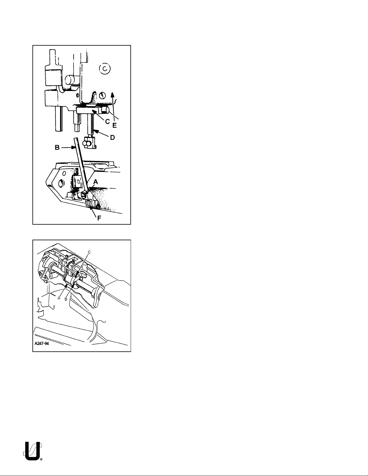
FIG. 2
SYNCHRONIZING NEEDLE AND LOOPER MOTIONS
NOTE: Needle and looper mechanisms are carefully synchronized with precision gauges before leaving the factory to insure the best possible sewing
conditions.
Should it become necessary to disassemble the main shaft or replace components of the needle or looper drive mechanisms, re-synchronization of the
machine will be required to facilitate proper sewing adjustments. This is accomplished by means of an adjustable split coupling located beneath the rear top
cover, connecting the crankshaft to the main shaft, which in turn drives the
looper mechanism.
To synchronize the machine, remove the needles, presser foot, throat plate,
feed dogs and upper feed roller mechanism. Rotate handwheel in the
operating direction until the needle bar is at the bottom of its stroke and just
begins its upward travel. Loosen screw (A, Fig. 2) and remove the looper for the
left hand needle from the looper holder. Insert a straight steel rod (B) 5/32"
(3.9mm) or 11/64" (4.3mm) diameter by 2-1/2" (63.5mm) long into looper holder
and retighten screw (A). Rotate the handwheel until the rod (B) is at the extreme
left and reinstall the throat plate. Loosen screw (F) in looper holder and move
the holder left or right until the right side of the rod is approximaately 5/32"
(4.0mm) from the left edge of the throat plate, tighten screw (F). Turn the
handwheel in the operating direction, with needle bar rising until rod (B) comes
in contact with the edge of the throat plate. At this point, clamp Union Special
timing gauge No. TT147 (C) around the needle bar (D), flush against the
underside of the machine casting (E). Rotate handwheel in the opposite
direction until either the gauge contacts the machine casting on the up stroke
of the needle bar or the rod contacts the edge of the throat plate. Maximum
allowable clearance between gauge and casting or rod and throat plate is
.005" (0.1mm)
If machine is not synchronized the following applies:
C
A
B
FIG. 3
Both ends of the adjustable split coupling are secured to the crankshaft and
main shaft by spot screws and set screws. On the main shaft end of the coupling
(A, Fig. 3) three screws (B) thread horizontally through the coupling. The holes
in the main shaft end of the coupling are larger than the diameter of the screws,
permitting several degrees of rotation in either direction to properly synchronize
the needle and looper. Loosen the three horizontal clamp screws (B, Fig. 3).
With rod (B, Fig. 2) at its farthest position to the left, snug the uppermost horizontal
clamp screw enough to hold coupling (A, Fig. 3) in position. If the handwheel
is turned in reverse of operating direction and gauge (C, Fig. 2) on needle bar
(D) contacts the machine casting (E) before rod (B) contacts the edge of the
throat plate, loosen horizontal clamp screw (B, Fig. 3) which was snug, while
holding the coupling in place with an Allen wrench in set screw (C). Rotate the
handwheel slightly in reverse of operating direction, snug the uppermost
horizontal clamp screw (B), recheck synchronization. If the handwheel is turned
in reverse of operating direction and the rod contacts the edge of the throat
plate before the clamp gauge contacts the machine casting, adjust as before,
except turn the handwheel slightly in the operating direction. Use shim stock to
insure no more than .005" (0.1mm) exists between gauge and casting or
between rod and throat plate, in both the operating and reverse directions of
the handwheel. When this setting has been made, tighten the three horizontal
clamp screws (B, Fig. 3) securely, and recheck both clearance points with .005"
(0.1mm) shim gauge to assure no slippage occurred while tightening the
screws.
10
TIGHTENING NEEDLE HEAD
When replacement of the needle bar, and or needle head is necessary, torque the needle head to needle bar 14-16 in. lbs. (1.6-1.8Nm)
or use torque rod No. 21227AR that has been supplied with the
machine, for the purpose of eliminating the possibility of distorting
the needle bar due to overtightening. Insert the torque rod in the
hole at the upper end of the needle bar, while holding the needle
bar head with a suitable tool, turn the needle bar with the torque rod
onto the needle bar head. When the rod starts to bend, the needle
bar head has been threaded into the needle bar properly.
ALIGNING NEEDLES IN THROAT PLATE SLOTS
Insert a new set of needles, type and size specified, with screw (B, Fig.
4) slightly loosened, lower needle bar (A) and turn needle head as
required until the needles are centered in the throat plate needle
hole slots. Tighten screw (B) torque to 19-21in.lbs. (2.1-2.4Nm).
NOTE: If the needles can not be aligned in the throat plate slots, the
lower cylinder must be moved as stated below.
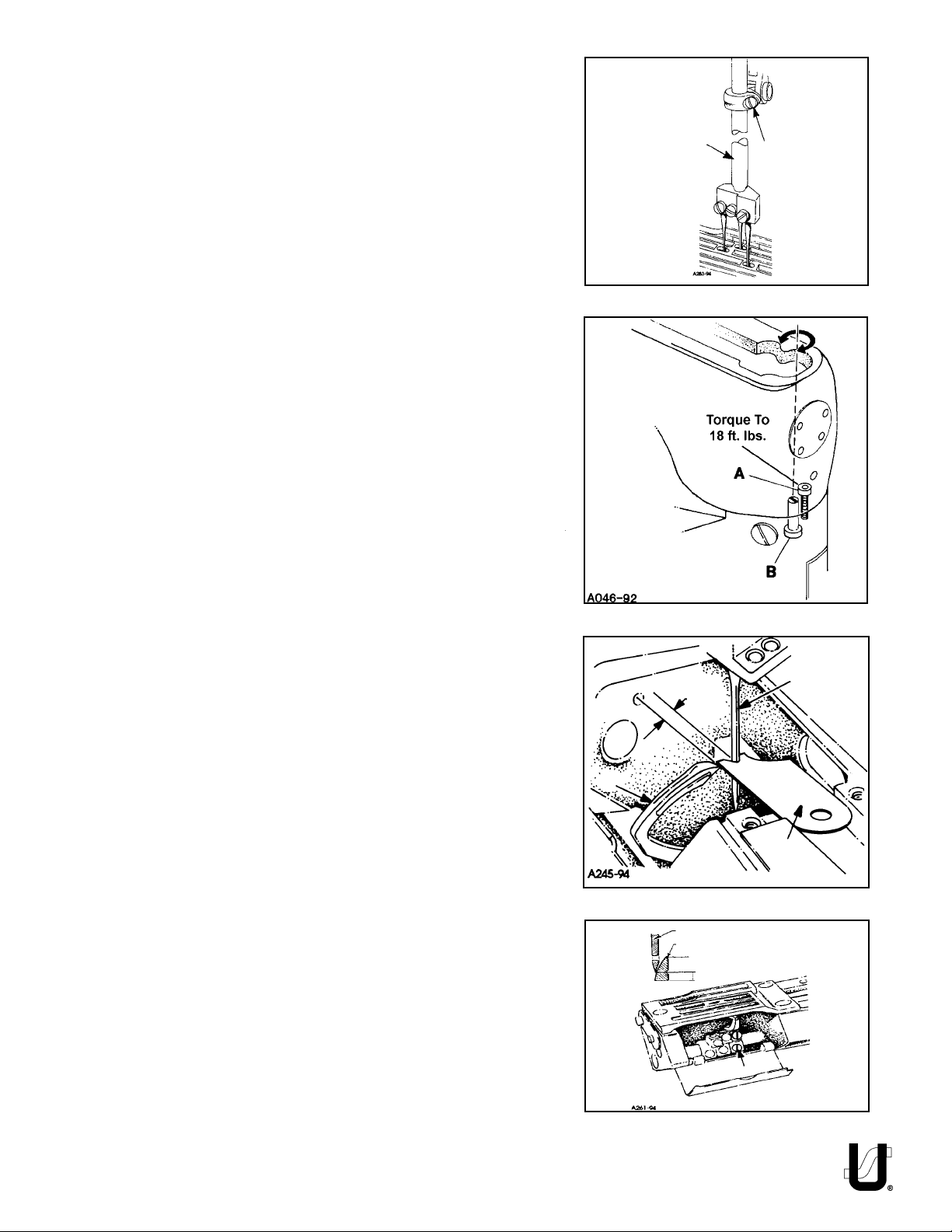
CENTERING THE CYLINDER
Remove the top front cover and gasket from the main frame. Loosen
cylinder holding screw (A, Fig. 5). Turn eccentric screw (B) clockwise
or counterclockwise to move the cylinder so the needles are
centered in the needle holes. Tighten screws (A) torque to 18 ft.lbs.
and recheck settings.
A
B
FIG. 4
NOTE: The cylinder may not move freely when the eccentric is
turned because the joint sealant compound has set.
SETTING THE LOOPER
Insert a new set of needles, type and size specified. Always adjust the
looper (A, Fig. 6) for the left needle first. Set the looper so that the
distance from the center of the needle (B) to the point of the looper
(A) is 9/64" (3.6mm) when the looper is at its farthest position to the
left. Looper gauge (C) No. 21225-9/64 can be used advantageously
in making this adjustment. If adjustment is required, loosen screw (A,
Fig. 7) in looper holder, permitting movement in either direction to
attain the 9/64" (3.6mm) dimension as shown in Fig. 6. Retighten
screw (A, Fig. 7). Repeat for other needles and loopers.
Rotate handwheel in operating direction to assure that the looper
point passes to the rear of the needle to touch but not deflect. This
adjustment can be made by loosening screw (A, Fig. 7) in looper
holder. Looper holder can be moved front to back to attain looper
to needle setting. Always check the 9/64" (3.6mm) looper gauge
setting after setting the looper to the back of the needle, and
conversely, always check the setting of the looper to the back of the
needle after setting the 9/64" (3.6mm) looper gauge.
The amount of looper avoid has been set at the factory to .110"
(2.8mm). If it becomes necessary to adjust the amount of avoid it is
recomended as a starting point, to have the points of the decending
needles contact the back of the lower 1/3 of the back of the
looper blade.
FIG. 5
B
9/64"
(3.6mm)
A
C
FIG. 6
Descending Needles
Looper Blade
Lower 1/3
A
11
FIG. 7
SETTING THE LOOPER (CONT.)
If more or less looper avoid motion is required, remove cylinder
side cover (A, fig. 8) located at the lower front left side. For plain
feed use a screwdriver to loosen looper avoid link ball joint (B).
For differential feed use Union Special wrench TT85 and loosen
screw stud (C) Moving ball joint down in the lever slot increases
the amount of looper avoid motion, moving it up acts the
reverse. Retighten ball joint (B), or screw stud (C) securely.
NOTE: Whenever looper avoid is changed looper clearance to
needle must also be reset.
FIG. 8
TORQUE:
19 - 21 in. lbs.
(2.1 - 2.4 Nm)
B
A
1/16" (1.6mm)
FIG. 9
B
A
C
D
The height of the needle bar is correct when the top of the
needle eye is 1/16" (1.6mm) below the underside of the looper,
with the looper point even with the right side of the needle. To
make adjustment loosen screw (A, Fig. 9) and move needle bar
(B) as required to attain dimension.
NOTE: Care must be taken not to disturb the alignment of the
needles when moving the needle bar either up or down.
Assemble the main feed dog and throat plate. Main feed dog
(A, Fig. 11) at its highest position, should be set to project above
the throat plate, the depth of its teeth. The feed dog mounting
screw (B) and front support screw (C) should be set to maintain
this setting.
The feed should be set so there is equal clearance between the
front of the feed dog and the front of the feed slot in the throat
plate when the feed dog is at its most forward travel. The same
amount of clearance should be between the back of the feed
dog and the back of the feed slot in the throat plate when the
feed dog is at its most rearward travel. To attain this setting
loosen screws (A and B, Fig. 10) and remove plug screw (D).
Using a screw driver turn eccentric pin (C) clockwise or counterclockwise to obtain proper setting. Tighten screws (A and B),
reinstall plug screw (D).
SETTING HEIGHT OF NEEDLE BAR
SETTING THE FEED DOGS FOR PLAIN FEED
Plain Feed
FIG. 10
B
Differential Feed
FIG. 10A
C
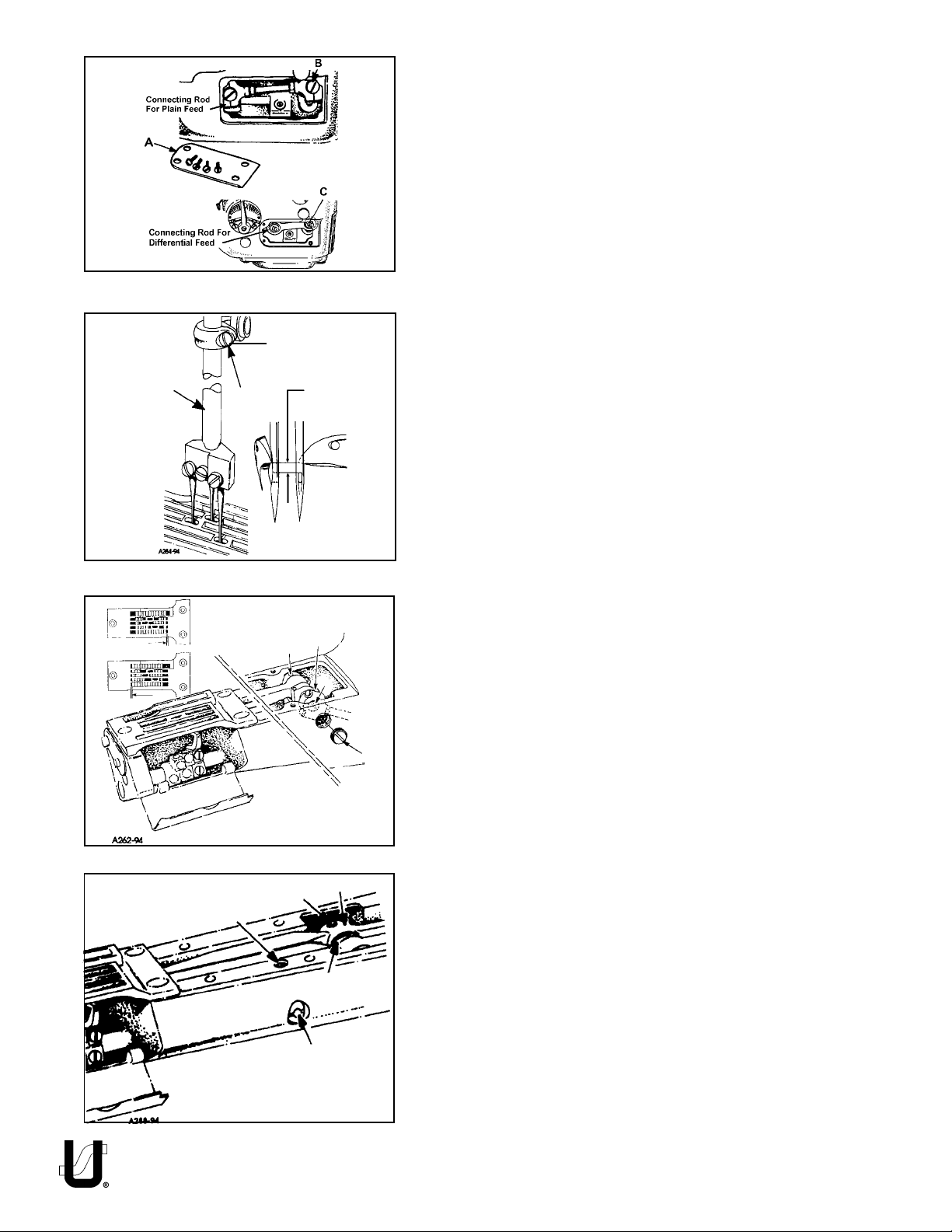
SETTING THE FEED DOGS FOR DIFFERENTIAL FEED
Before assembling the main and differential feed dogs, set the
feed bar eccentric pin (A, Fig. 10A) located in the left side near
D
E
A
center of cylinder, so that the slot in the head is in a horizontal
position for the 35800DLU, DNU, and DZ style machines and
turned counter clockwise to an approximate 45° for the
35800DWW style of machine. The pin can be used to slightly tilt
both feed dogs if necessary. The feed bar pin is retained in
position by set screw (B). Assemble differential feed dog (A, Fig.
11A), main feed dog (B) and throat plate. Both the main and
differential feed dogs can be individually adjusted to height.
Main feed dog (B) at its highest position, should be set to project
above the throat plate, the depth of its teeth. If adjustment is
necessary loosen screw (D) and move feed dog (B) up or down
to attain correct setting. Feed dog support (C) should support
front of feed dog.
NOTE: If eccentric pin (A, Fig. 10A) is used to tilt the feed dogs,
make sure that the looper does not interfere with the rear
needle guard and that the needle guard does not pinch
the needle loops on the back side of the needles.
12
SETTING THE FEED DOGS FOR DIFFERENTIAL FEED (CONT.)
If adjustment is necessary loosen screw (E, Fig. 11A) in feed dog
support (C) and move as required. Retighten screw (E). The
differential feed dog (A) may then be leveled with main feed dog
(B). If adjustment is necessary loosen screw (F) and move feed
dog up or down as required. Retighten screw (F).
NOTE: Should the main feed dog require repositioning due to
contact with the throat plate in its forward or rearward
travel, loosen set screw (C, Fig. 10A) in main feed bar
driving link (D), rotate main feed bar eccentric driving
stud (E) as required. Driving stud (E) has a thin hexagon
head with cutouts on two of the flats allowing movement by tapping with a sharp pointed tool, when wrench
21388AZ is not available. Whenever the main feed bar
eccentric driving stud position has been changed, recheck rear needle guard setting, adjustment may be
required. Retighten set screw (C). Position main feed
dog support (C, Fig. 11A) flush against bottom of main
feed dog (B), tighten support screw (E) securely.
CHANGING STITCH LENGTH
When change in stitch length is required, remove large plug screw
(A, Fig. 12). Loosen feed rocker driving link screw (B) in lever (C).
Moving the feed rocker driving link up in the lever slot lengthens
the stitch, moving it down, shortens the stitch. Retighten link screw
(B) securely and replace plug screw (A).
NOTE: If plug screw (A) is replaced with a new plug screw, it
should be sealed with a silicone seal.
C
A
B
Plain Feed
FIG. 11
A
C
B
E
D
Differential Feed
F
FIG. 11A
Any stitch length change, requires resetting the needle
guard.
CAUTION: When making stitch length adjustment do not exceed
maximum recommended stitch length due to possible
part damage.
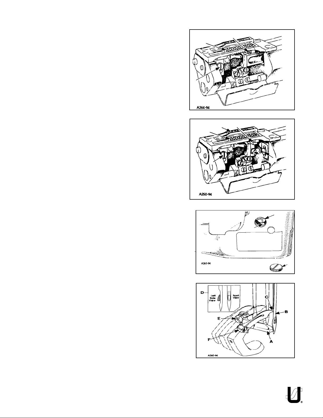
SETTING REAR NEEDLE GUARD
Set the rear needle guard (A, Fig. 13) horizontally to touch and
possibly deflect slightly to obtain solid guarding of all needles
(B) when at its extreme forward position. If adjustment is necessary loosen screw (E) and move guard front to back as required.
It should be set vertically as low as possible, yet have its guarding surface in contact with the needles until the points of the
loopers (C), moving to the right, are even with the right side of
the needles. If adjustment is necessary loosen screw (F) and
move guard and holder up or down as required.
CAUTION: If stitch length is changed, needle guard must be
reset.
NOTE: When installing the needle it should be parallel with the
eye in line of feed. If adjustment is necessary, loosen
screw (N, Fig. 15) in needle head and rotate needle to
attain adjustment (D, Fig. 13).
B
C
A
FIG. 12
FIG. 13
NOTE: Looper closeness to needles as described on page 11
must be maintained after rear needle guard is adjusted. Readjust loopers as necessary.
13
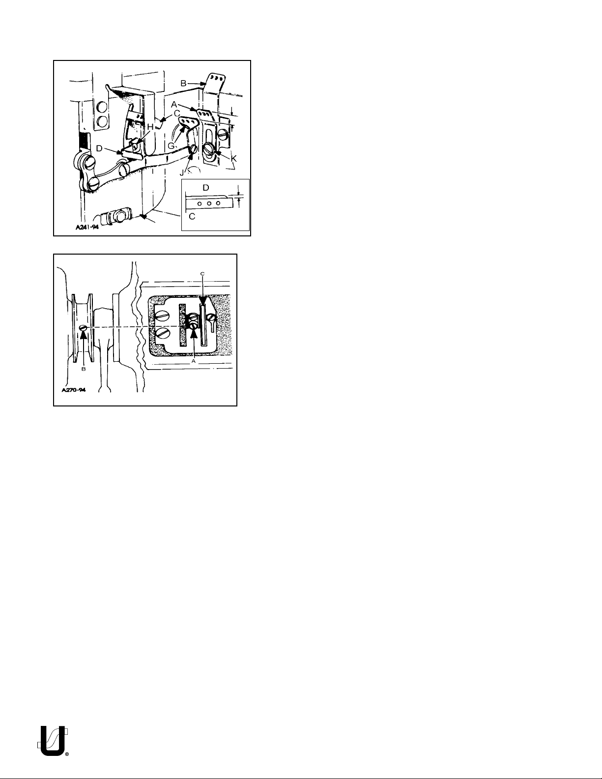
PRESSER FOOT AND PRESSER BAR ADJUSTMENT
Adjusting or Replacing Presser Foot:
Remove presser bar leaf spring (B, Fig. 14) and nut (B). Loosen screw
(A, Fig. 15) on presser bar guide (B). Loosen screws (C) in upper
collar and screws (D) in needle lever thread pull-off lever.. Slide
presser bar upward high enough to slip on presser foot yoke (E) with
foot attached and tighten screw (F) on flat of presser bar. Position
foot so that the needle holes in the foot line up with the holes in the
throat plate. Tighten screw (A)
Presser foot guide plates (G, Fig. 15) should be set so that entire
presser foot and bar assembly has free movement up and down
with no left to right movement.
FIG. 14
FIG. 15
With foot properly aligned on throat plate and presser bar guide (B,
Fig. 15) securely fastened to presser bar, adjust both guide plates
(G) to obtain above setting. Tighten four screws (H).
Reinstall presser bar spring (B, Fig. 14) and knob (A), with presser foot
resting on throat plate.
Set upper stop collar (K) to contact casting, so the bottom of the
needle head and the top of the presser foot do not touch, at the
bottom of the needle stroke when lifting foot. Tighten screw (C).
The presser foot should be adjusted to be 1/8" (3.17mm) above the
throat plate before the feed roller mechanism begins to rise.. Loosen
screw (A, Fig. 15) in presser bar lifter and guide (B), raise or lower
guide as required to attain the specified point at which the feed
roller begins to rise. Retighten screw (A) and maintain needle
settings.
NOTE: There should be a minimum 1/32" (0.8mm) clearance
between screw (M, Fig. 15) and the bottom of the slot in link
(J).
Regulate the pressure on the presser foot by turning the presser spring
regulating knob (A, Fig. 14) located on top of pressure foot spring (B)..
To remove just the presser foot, remove screws (L, Fig. 15) and replace
foot, retighten screws (L).
Needle lever thread pull-off (P) should be set 1/16 (1.6mm) above
bottom of slot in cover (Q) when presser foot is resting on throat plate.
UPPER FEED ROLLER ADJUSTMENT
C
D
E
B
H
A
F
G
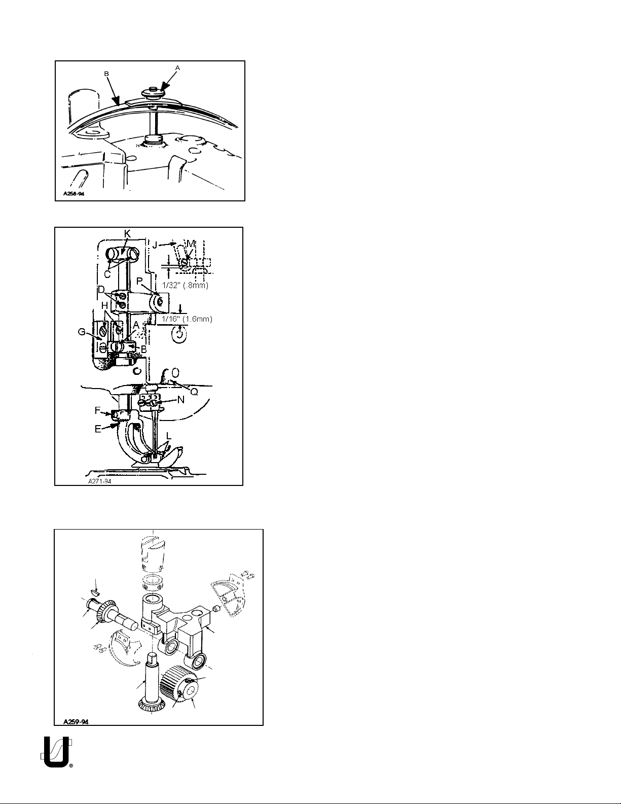
Assembly of Roller to Roller Yoke:
Assemble driven gear (A, Fig.16) through feed roller frame (B).
Place woodruff key (C) into slot of feed roller shaft (D). Slide
driven gear (E) on to shaft (D), make sure key (C) goes into slot
in gear (E). While holding feed roller frame (B) with steel roller
(F) between the two frame lobs, slide feed roller shaft (D) and
assembled components through frame. Make sure that shoulder of roller (F) is to the right. Align screw (G) (first in operating
direction on roller) on the flat of shaft (E). At the same time thrust
shoulder of shaft (D) against face of gear (E), make sure left
edge of roller is against right (inside) face of left lob. Secure
screw (G) on flat of shaft (D) and tighten screw (H).
FIG. 16
14
UPPER FEED ROLLER ADJUSTMENT (CONT.)
When feed roller mechanism (C, Fig. 17) has been removed or replaced, .003" (0.08mm) minimum to .005"
(0.13mm) maximum clearance should be maintained
between roller and throat plate.
To Adjust Guiding System for Roller:
Loosen two screws (A). Using shim(s) adjust feed roller
mechanism (C) so that the roller is .003" (0.08mm) to .005"
(0.13mm) above throat plate. Slide rear guide finger (B)
down so that it sits on top of rear guide support block (D).
Check to make sure roller is parallel to throat plate slots.
Tighten two screws (A) to secure feed roller mechanism in
place. For machine style 35800DLU, with roller on throat
plate set 1/32" gap between bottom of rear guide finger
(B) and top of rear guide support block (D).
Setting Pressure for Feed Roller:
Regulate the pressure on the feed roller so that it exerts
only enough pressure on the fabric to feed the work
uniformly. Turning roller presser spring regulator (H, Fig.
17) clockwise to increase or counterclockwise to decrease the pressure.
Setting of Feed Roller:
Guide finger for roller should be set so that entire roller
mechanism has free movement up and down with no left
to right movement. With roller properly aligned, the edge
of roller should be parallel with feed slots in throat plate.
Guide plates (F) must be thrusted against guide finger (B) to
secure feed roller mechanism (C). Thrust guide plates (F)
against guide finger (B) with equal pressure. Tighten four
screws (E) to hold plates in place.
THREAD TENSION AND RELEASE
The thread tension release is set correctly when it begins to
function at the point when the upper feed roller begins to
rise. When adjustment is necessary, loosen screw (B, Fig. 18)
in lifter lever (C). Facing the tension release shaft (A) from
the right end of the machine, insert screwdriver in slot in
shaft (A). Turn the screwdriver clockwise to raise pins (D) or
counterclockwise to lower pins. Retighten screw (B).
DIFFERENTIAL CONTROL
The amount of differential is controlled by lever (A, Fig. 19).
The adjusting plate is numbered from 1 to 9. When the lever
is set from numbers 1 to 4 reverse differential or stretching
occurs. The numbers from 4 to 5 produce equal feed stitching while numbers 5 to 9 produce a gathering stitch. Screws
(B) can be set to limit the movement of lever (A) or lock lever
in one position. If top ply of material is coming out long,
move lever toward operator, if top ply is short, move lever
away from operator, as required.
FIG. 17
FIG. 18
A
B
B
15
FIG. 19
SETTING NEEDLE THREAD TAKE-UP AND FRAME EYELET
With the needle bar at the top of its stroke set the adjustable
frame needle thread eyelet (A, Fig. 20) in the lower mounting
hole of eyelet (B) so the needle thread from eyelet (A) to the
needle lever thread eyelet (C) will be in a straight line. If
adjustment of eyelet (A) is necessary loosen screw (K) and
move eyelet up or down as required. Retighten screw (K).
With the needle bar at the bottom of its stroke, the needle
thread take-up (D) should be set so that it is 1/16" (1.6mm)
above the edge of the needle lever thread eyelet (C) (See
Inset). If adjustment is necessary loosen screw (H) and adjust
lever (D) as required to attain 1/16". Tighten screw (H).
FIG. 20
FIG. 21
1/16"
(1.6mm)
LOOPER THREAD TAKE-UP ADJUSTMENT
With the machine rotating in operating direction the looper
thread take-up is in time when the first screw coming into
view (A, Fig. 21) is in line with the spot screw (B) on the main
shaft in the pulley. NOTE: screw (A) is accessable through the
hole in the take-up. With this setting correct, the looper
thread should cast-off of the take-up (C) when the needles
are safely in the triangle. If adjustment is necessary loosen
two screws (A) in take-up (C) position screws in line with spot
screw (B). Tighten screws (A).
NOTE: Make sure take-up cam is centered left to right in
cast-off slot.
16
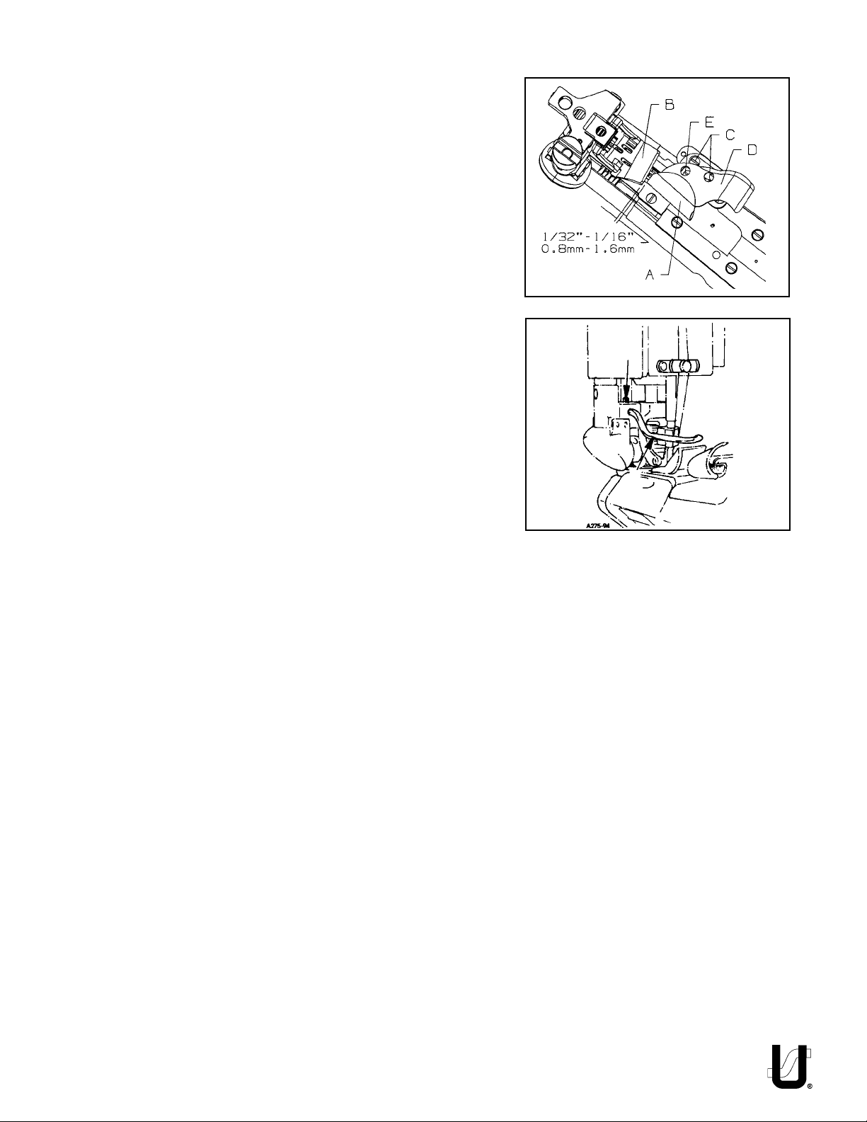
FOLDER ADJUSTMENT
Slide folder (A, Fig. 22) on arm. The folder should be as close to
the front of presser foot (B) as possible, making sure to avoid the
presser foot contacting the folder when sewing across seams. If
adjustment is necessary loosen screws (C) to move entire folder
left to right or front to back as required. If just adjustment of
upper scroll (D) is needed loosen screw (E) and position scroll to
obtain proper seam margin.
AIR BLOWER TUBE ADJUSTMENT
The air blower tube should be set left to right so it is parallel with
the throat plate. It should be set front to back so when feeding
over a cross seam the presser foot does not contact the tube. If
adjustment is necessary, loosen screw (A, Fig. 23) and position
air blower tube (B) as required. Retighten screw (A).
FIG. 22
A
B
FIG. 23
17
18
 Loading...