


 Loading...
®
Feed-off-the-arm, 4-needle “Flatseamer” for Top and Bottom Coverstitch
36200 Series Minute-quantity
lubrication
ENGINEER’S MANUAL
40040898
No.E373-00
Introduction
This Engineer’s Manual is written for the technical personnel who are responsible for the service and maintenance of the machine.
The maintenance services to be done on this sewing machine should be based on this manual.
This manual gives the "Standard Adjustment" on the former section under which the most basic adjustment value is described and on the latter section the "Results of Improper Adjustment" under which stitching errors and troubles arising from mechanical failures and "How To Adjust" are described.
From the library of Superior Sewing Machine & Supply LLC - www.supsew.com
|
|
|
CONTENTS |
|
1. |
Specifications ........................................................................................................ |
1 |
||
2. |
List of models ........................................................................................................ |
2 |
||
3. |
Model numbering system ............................................................................ |
3 |
||
4. |
Configuration................................................................................................. |
4 |
||
|
(1) Head names .............................................................................................................................. |
4 |
||
|
(2) |
Names of presser body ........................................................................................................... |
5 |
|
5. |
Needles ......................................................................................................... |
6 |
||
|
(1) |
Needle types ............................................................................................................................. |
6 |
|
|
(2) |
Features of needles ................................................................................................................. |
6 |
|
|
(3) |
Needle applications ................................................................................................................. |
6 |
|
6. How to conduct threading ........................................................................... |
7 |
|||
7. Standard adjustment .............................................................................................. |
8 |
|||
|
(1) |
Presser removal work ...................................................................................................... |
8 |
|
|
(2) |
Adjusting the height of the needle bar ......................................................................... |
10 |
|
|
(3) |
Adjustment of needle array ........................................................................................... |
12 |
|
|
(4) |
Right and left needle entry position adjustments ....................................................... |
14 |
|
|
(5) |
Looper adjustment ......................................................................................................... |
16 |
|
|
|
1) |
Returning amount of the looper ......................................................................................................... |
16 |
|
|
2) |
Adjustment of a clearance between looper and needle ..................................................................... |
16 |
|
(6) |
Adjustment of looper and needle bar timing ..................................................................... |
18 |
|
|
(7) |
Adjustment of looper movement......................................................................................... |
20 |
|
|
(8) |
Adjustment of looper movement locus .............................................................................. |
22 |
|
|
(9) |
Adjustment of the feed dog ................................................................................................. |
24 |
|
|
(10) Adjustment of needle holder ............................................................................................... |
26 |
||
|
|
1) |
Adjustment of rear needle holder ....................................................................................................... |
26 |
|
|
2) |
Adjustment of forward movement needle holder ............................................................................... |
26 |
|
(11) Adjustment of feed mechanisms ........................................................................................ |
28 |
||
|
|
1) |
Stitch length adjustment .................................................................................................................... |
28 |
|
|
2) |
Adjustment of differential feed amount .............................................................................................. |
28 |
|
(12) Adjustment of presser main body mounting ..................................................................... |
30 |
||
|
(13) Adjustment of the presser main body proper .................................................................... |
32 |
||
|
|
1) |
Adjustment of presser lifter connecting lever ..................................................................................... |
32 |
|
|
2) |
Adjustment of presser lifting strap plunger ........................................................................................ |
32 |
|
|
3) |
Adjustment of minute presser lifting ................................................................................................... |
32 |
|
(14) Adjustment of top fancy looper and fancy thread carrier ................................................. |
34 |
||
|
|
1) |
Stroke position adjustment of drive sleeve ........................................................................................ |
34 |
|
|
2) |
Amount of fancy thread carrier injection ............................................................................................ |
34 |
|
|
3) |
Leftmost point of top fancy looper ...................................................................................................... |
36 |
|
|
4) |
Clearance developed at the time of crossing between the fancy thread carrier and |
|
|
|
|
the tip of the top fancy looper ............................................................................................................ |
36 |
|
|
5) |
Rightmost point of top fancy looper ................................................................................................... |
36 |
|
|
6) |
Height of top fancy looper .................................................................................................................. |
36 |
|
(15) Adjustment of top fancy cam and bobbin thread cam ...................................................... |
38 |
||
|
|
1) |
Adjustment of top fancy cam ............................................................................................................. |
38 |
|
|
2) |
Adjustment of bobbin thread cam ...................................................................................................... |
38 |
From the library of Superior Sewing Machine & Supply LLC - www.supsew.com
(16) |
Knife adjustment .................................................................................................................. |
40 |
|
|
1) |
Lower knife adjustment ...................................................................................................................... |
40 |
|
2) |
Upper knife adjustment ...................................................................................................................... |
40 |
|
3) |
Pressure adjustment of upper knife ................................................................................................... |
40 |
(17) Adjustment of upper knife drive lever ................................................................................ |
42 |
||
(18) |
Adjustment of needle thread path ...................................................................................... |
44 |
|
|
1) |
Adjustment of needle thread guide bar .............................................................................................. |
44 |
|
2) |
Adjustment of needle holder adjusting pin ......................................................................................... |
44 |
|
3) |
Adjustment of needle thread presser spring ...................................................................................... |
44 |
(19) |
Adjustment of tension disk rise and protection cover ..................................................... |
46 |
|
|
1) |
Adjustment of tension disk rise .......................................................................................................... |
46 |
|
2) |
Adjustment of protection cover .......................................................................................................... |
46 |
(20) |
Adjustment of lapformer ...................................................................................................... |
48 |
|
8. Lubrication ........................................................................................................... |
50 |
|
9. List of rear spring ................................................................................................ |
51 |
|
(1) |
One side trim ......................................................................................................................... |
51 |
(2) |
Both side trim ........................................................................................................................ |
52 |
(3) |
Taping .................................................................................................................................... |
53 |
(4) |
Step gauge ............................................................................................................................ |
53 |
(5) |
Butted seam .......................................................................................................................... |
53 |
10. Types of feed dogs .............................................................................................. |
54 |
|
11. Maintenance ......................................................................................................... |
55 |
|
(1) Spare parts ............................................................................................................................. |
55 |
|
12. Troubles and corrective measures ............................................................ |
56 |
|
13. Table drawing .............................................................................................. |
68 |
|
(1) |
Auxiliary drive table .............................................................................................................. |
68 |
(2) |
Auxiliary drive sub-table ...................................................................................................... |
69 |
From the library of Superior Sewing Machine & Supply LLC - www.supsew.com
1. Specifications
No. |
Model name |
|
|
|
Application |
|
||
|
Item |
36200L/36200U |
|
36200T |
|
36200L220 |
||
|
|
|
|
|
|
|
|
|
1 |
Application |
General light-weight - |
|
Intended for taping |
|
For light-weight (swimsuits) |
||
medium-weight materials |
|
|
materials |
|||||
|
|
|
|
|
||||
|
|
|
|
|
|
|
||
2 |
Sewing type |
4-needle both side trim |
|
4-needle one side trim |
|
5-needle both side trim |
||
fancy sewing |
|
fancy sewing |
|
fancy sewing |
||||
|
|
|
|
|||||
|
|
|
|
|
|
|
||
3 |
Max. sewing speed (normal) |
4,200rpm (normal sewing speed: 3,200rpm) |
|
4,200rpm (normal: 2,500rpm) |
||||
|
|
|
|
|
|
|
||
4 |
Stitch length |
1.6 to 2.5mm (Standard 2.1mm) |
|
1.6 to 1.8mm (standard 1.6mm) |
||||
|
|
|
|
|
|
|
||
5 |
Needle gauge |
5.2mm, 6.0mm |
|
6.0mm |
||||
|
|
|
|
|
|
|
|
|
6 |
Needle bar stroke |
|
|
|
30mm |
|
||
|
|
|
|
|
|
|
||
7 |
Needles to be used |
UY118GKS065 to 080 (#9 to #12) |
UY116GKS065 |
|||||
(Standard needle count) |
* (Standard 70/ #10) |
|
|
(Standard 80/ #12) |
(Standard 65/ #9) |
|||
|
|
|||||||
|
|
|
||||||
|
|
|
||||||
|
|
|
|
|
|
|
|
|
8 |
Retainer needles to be used |
36211-060 to 075 |
|
|||||
(Standard needle count) |
* (Standard 65/ #9) |
(Standard 75/ #11) |
|
|||||
|
|
|||||||
|
|
|
||||||
|
|
|
|
|
|
|
|
|
9 |
No. of threads used |
6 pcs. |
5 pcs. |
7 pcs. |
||||
|
|
|
|
|
|
|||
10 |
Feed control system |
Main feed ----- Slide type stitch pitch control system |
||||||
Differential feed ------------ Lever control system |
||||||||
|
|
|||||||
|
|
|
|
|
|
|||
11 |
Lubrication |
Rotary pump type auto lubrication (minute-quantity lubrication to needle bar and looper sections) |
||||||
|
|
|
|
|
|
|
||
12 |
Quantity of oil storage |
Front oil storage: 70ml to 80ml |
|
|||||
|
|
|
|
|
|
|||
|
|
Rear oil storage: 60ml to 70ml |
|
|||||
|
|
|
|
|
|
|||
13 |
Lubricating oil |
Union Special Specification 175 (equivalent to ISO VG22) or |
||||||
|
|
|
|
|
|
|||
|
|
|
|
|
JUKI Oil SUP2000 – 1L |
|
||
|
|
|
|
|
|
|||
14 |
Installation system |
Table and Aux. Drive mounting system |
||||||
|
|
|
|
|
Pedestal mounting system |
|
||
|
|
|
|
|
|
|||
15 |
Lifting amount of presser |
One side trim type 8.0mm, both side trim type 6.0mm |
||||||
|
|
|
|
|
|
|
|
|
16 |
Minute presser lifting |
|
|
|
Provided as standard |
|
||
|
|
|
|
|
|
|
|
|
17 |
Needle thread silicone tank |
|
|
|
Provided as standard |
|
||
|
|
|
|
|
|
|||
18 |
External dimensions |
Height 31.5mm x Width 25.5mm x Depth 42.5mm |
||||||
|
|
|
|
|
|
|
|
|
19 |
Weight of head |
|
|
|
22kg |
|
||
|
|
|
|
|
|
|
||
20 |
Working temperature/humidity |
Temperature : 5°C to |
35°C, Humidity : 35% to 85% (no condensation) |
|||||
|
|
|
|
|
|
|
||
21 |
Supply voltage/frequency |
Rated voltage ±10% 50 / 60Hz |
|
|||||
|
|
|
|
|
|
|
|
|
*For standard usage in Japan, the needle count is [Standard 65/#9]. The needle count for retainer needles is [Standard 60/ #8].
– 1 –
From the library of Superior Sewing Machine & Supply LLC - www.supsew.com
2. List of models
The standard models are the lapseamers with 4 needles and 6 threads for vertical fancy stitch.
According to the model names, they are classified into specifications for the specific gauges, step gauges, taping, and multi-purpose.
Model name |
Application |
Number of |
Retainer |
Number of |
Top fancy |
Knife |
Lapformer |
|
needle |
needle |
threads |
||||||
|
|
|
|
|
||||
|
|
|
|
|
|
|
|
|
|
|
|
|
|
|
|
|
|
|
General knit goods |
|
|
|
|
|
|
|
36200L100-52 |
|
4 |
1 |
6 |
With |
One side trim |
Without |
|
Lightand medium-weight |
||||||||
|
|
|
|
|
|
|
||
|
materials |
|
|
|
|
|
|
|
|
|
|
|
|
|
|
|
|
36200L100-60 |
General knit goods |
4 |
1 |
6 |
With |
One side trim |
Without |
|
|
|
|
|
|
|
|
|
|
|
|
|
|
|
|
|
|
|
|
General knit goods |
|
|
|
|
|
|
|
36200L200-52 |
|
4 |
1 |
6 |
With |
Both side trim |
With |
|
Lightand medium-weight |
||||||||
|
|
|
|
|
|
|
||
|
materials |
|
|
|
|
|
|
|
|
|
|
|
|
|
|
|
|
|
General knit goods |
|
|
|
|
|
|
|
|
|
|
1 |
|
|
|
|
|
36200L200-60 |
Lightand medium-weight |
4 |
|
6 |
With |
Both side trim |
With |
|
materials |
|
|||||||
|
||||||||
|
|
|
|
|
|
|
||
|
|
|
|
|
|
|
|
|
|
Swimsuits |
|
0 |
|
|
|
|
|
|
|
|
|
|
|
|
|
|
|
|
|
|
|
|
|
|
|
|
Specific gauges |
|
|
|
|
|
|
|
|
(Thigh patch-up for |
|
|
|
|
|
|
|
36200L202-52 |
boxer's briefs, etc.) |
4 |
1 |
6 |
With |
Both side trim |
With |
|
|
|
|
|
|
|
|
|
|
|
Medium-weight materials |
|
|
|
|
|
|
|
|
|
|
|
|
|
|
|
|
|
Specific gauges |
|
|
|
|
|
|
|
|
(Thigh patch-up for |
|
|
|
|
|
|
|
36200L202-60 |
boxer's briefs, etc.) |
4 |
1 |
6 |
With |
Both side trim |
With |
|
|
|
|
|
|
|
|
|
|
|
Medium-weight materials |
|
|
|
|
|
|
|
|
|
|
|
|
|
|
|
|
|
|
|
|
|
|
|
|
|
|
1.27mm step gauges |
|
|
|
|
|
|
|
36200L210-52 |
|
4 |
1 |
6 |
With |
Both side trim |
With |
|
Mediumand heavy- |
||||||||
|
|
|
|
|
|
|
||
|
weight materials |
|
|
|
|
|
|
|
|
|
|
|
|
|
|
|
|
|
1.27mm step gauges |
|
|
|
|
|
|
|
36200L210-60 |
|
4 |
1 |
6 |
With |
Both side trim |
With |
|
Mediumand heavy- |
||||||||
|
|
|
|
|
|
|
||
|
weight materials |
|
|
|
|
|
|
|
|
|
|
|
|
|
|
|
|
|
|
|
|
|
|
|
|
|
36200T300-52 |
Fly taping |
4 |
1 |
5 |
Without |
One side trim |
Without |
|
|
|
|
|
|
|
|
|
|
36200T300-60 |
Fly taping |
4 |
1 |
5 |
Without |
One side trim |
Without |
|
|
|
|
|
|
|
|
|
|
|
|
|
|
|
|
|
|
|
|
Multi-purpose |
|
|
|
|
|
|
|
36200U300-52 |
|
4 |
1 |
6 |
With |
Combined use |
Combined use |
|
Lightand medium-weight |
||||||||
|
|
|
|
|
|
|
||
|
materials |
|
|
|
|
|
|
|
|
|
|
|
|
|
|
|
|
|
Multi-purpose |
|
|
|
|
|
|
|
36200U300-60 |
|
4 |
1 |
6 |
With |
Combined use |
Combined use |
|
|
Lightand medium-weight |
|
|
|
|
|
|
|
|
materials |
|
|
|
|
|
|
|
|
|
|
|
|
|
|
|
(Caution) The list shows the models exclusive for 4 needles. It does not include the models for 5 needles.
– 2 –
From the library of Superior Sewing Machine & Supply LLC - www.supsew.com

3. Model numbering system
Name: Feed-off-the-arm 4-needle “Flatseamer” for Top and Bottom Coverstitch
1 |
2 |
3 |
4 |
5 |
6 |
7 |
8 |
9 |
10 |
11 |
12 |
13 |
14 |
15 |
|||
3 |
6 |
2 |
0 |
0 |
|
|
|
|
|
|
|
|
|
— A A |
|||
|
|
|
|
|
|
|
|
|
|
|
|
|
|
|
|||
6 to 9 |
|
|
|
|
|
|
|
|
|
Head specifications |
|
|
|||||
|
|
|
|
|
|
|
|
|
|
|
|
|
|||||
Code |
|
|
Specifications |
|
|
Cloth cutting |
|
|
|
|
|
Applications |
|||||
|
|
|
|
|
|
|
|
|
|
|
|
|
|||||
L100 |
|
|
Lapseam |
|
|
|
One side trim |
|
|
|
|
With edge guide spreader |
|||||
|
|
|
|
|
|
|
|
|
|
|
|
|
|||||
L200 |
|
|
Lapseam |
|
|
|
Both side trim |
|
|
|
|
With lapformer spreader |
|||||
|
|
|
|
|
|
|
|
|
|
|
|
||||||
L202 |
|
|
Lapseam |
|
|
|
Both side trim |
|
|
|
Specific both side trim gauge lapformer |
||||||
|
|
|
|
|
|
|
|
|
|
|
|
|
|
|
|
|
With spreader |
|
|
|
|
|
|
|
|
|
|
|
|||||||
L210 |
|
|
Lapseam |
|
|
|
Both side trim |
|
Both side trim 1.27mm, step presser, throat plate, feed dog |
||||||||
|
|
|
|
|
|
|
|
|
|
|
|
|
|
|
|
With lapformer spreader |
|
|
|
|
|
|
|
|
|
|
|
|
|
||||||
L220 |
|
|
Lapseam |
|
|
|
Both side trim |
|
|
|
Specific 5-needle presser, lapformer |
||||||
|
|
|
|
|
|
|
|
|
|
|
|
|
|
|
|
With spreader (for swimsuits) |
|
|
|
|
|
|
|
|
|
|
|
|
|||||||
T300 |
|
|
Taping |
|
|
Combined use for one side |
|
|
|
Without spreader, tape reel |
|||||||
|
|
|
|
|
|
|
|
|
and both side trim |
|
|
|
|
With tape folder |
|||
|
|
|
|
|
|
|
|
|
|
|
|
|
|
||||
U300 |
|
|
Multi-purpose |
|
Combined use for one side |
|
|
|
Multi-purpose specifications |
||||||||
|
|
|
|
and both side trim |
|
|
|
||||||||||
|
|
|
|
|
|
|
|
|
|
|
|
|
|
||||
|
|
|
|
|
|
|
|
|
|
|
|
|
|
|
|||
|
|
|
|
|
|
|
|
|
|
|
|
|
|
|
|||
10 to 11 |
|
|
|
|
Needle gauge |
|
|
|
|
|
|
|
|
||||
|
|
|
|
|
|
|
|
|
|
|
|
|
|
|
|
|
|
|
52 |
|
|
|
|
|
5.2mm |
|
|
|
|
|
|
|
|
||
|
|
|
|
|
|
|
|
|
|
|
|
|
|
|
|
|
|
|
60 |
|
|
|
|
|
6.0mm |
|
|
|
|
|
|
|
|
||
|
|
|
|
|
|
|
|
|
|||||||||
* Head spec. L220 applicable to 60 (6.0mm) only |
|
|
|
|
|
|
|||||||||||
|
|
|
|
|
|
|
|
|
|
|
|
|
|
|
|
||
|
12 |
|
|
|
|
|
Region |
|
|
|
|
|
|
|
|
||
|
|
|
|
|
|
|
|
|
|
|
|
|
|
|
|
|
|
|
J |
|
|
|
|
|
|
Japan |
|
|
|
|
|
|
|
|
|
|
|
|
|
|
|
|
|
|
|
|
|
|
|||||
|
N |
|
|
|
North America, Europe |
|
|
|
|
|
|
|
|||||
|
|
|
|
|
|
|
|
|
|
|
|
|
|
|
|
|
|
|
S |
|
|
|
|
|
|
Asia |
|
|
|
|
|
|
|
|
|
|
|
|
|
|
|
|
|
|
|
|
|
|
|
|
|
|
|
*Head spec. L100 only, Impossible to select J J (for Japan) of L100 covered by S
14 |
Place pf destonation |
|
|
A |
Standard |
|
|
|
|
15 |
Accessories type |
|
|
A |
Standard |
|
|
– 3 –
From the library of Superior Sewing Machine & Supply LLC - www.supsew.com

4. Configuration
(1) Head names
|
|
|
|
|
|
|
|
|
|
|
|
|
|
|
|
|
|
|
|
|
|
|
|
|
|
|
|
|
|
|
|
|
|
|
|
|
|
|
|
|
|
|
|
|
|
|
|
|
|
|
|
|
|
|
|
|
|
|
|
|
|
|
|
Presser pressure stroke adjusting screw |
Frame needle thread path |
Looper cover |
|||||
Needle bar guard |
Needle thread guide bar |
Presser |
|||||
Rear top cover |
Thread path frame |
Face cover |
|||||
Lift lever |
Looper thread guide |
Minute presser lifting |
|||||
Oil circulator check window (rear) |
Stitch length control window screw |
Swing guard |
|||||
Oil gauge (rear) |
Oil gauge (front) |
Protection cover |
|||||
Needle thread silicone unit |
Oil drain screw (front) |
Lapformer |
|||||
Thread tension knob |
Cylinder side cover |
Oil drain screw (rear) |
|||||
Thread guide |
Differential adjusting lever |
Pulley |
|||||
Oil circulator check window (front) |
Scale plate feed |
Needle thread rocking guide |
|||||
Threading guard (Assy) |
Feed dog eccentric pin |
Needle thread holder adjusting pin |
|||||
|
|
|
|
|
|
|
Front top cover |
– 4 –
From the library of Superior Sewing Machine & Supply LLC - www.supsew.com
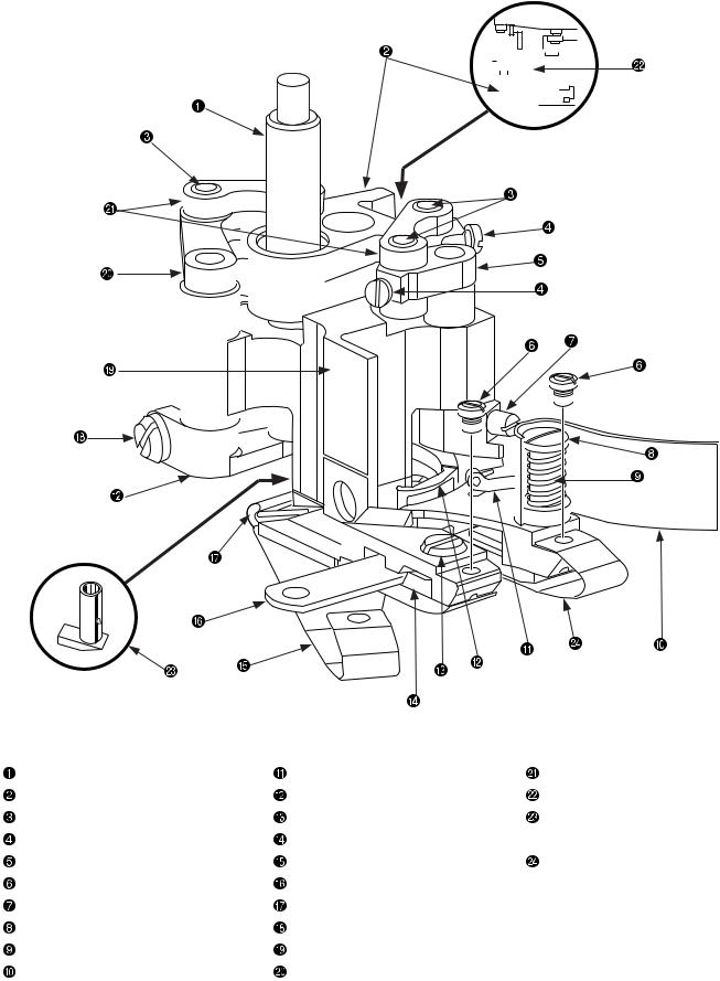
(2) Names of presser body
|
|
|
|
|
|
|
|
|
|
|
|
|
|
|
|
|
|
|
|
|
|
|
|
|
|
|
|
|
|
|
|
|
|
|
|
|
|
|
|
|
|
|
|
|
|
|
|
|
|
|
|
|
|
|
|
|
|
|
|
|
|
|
|
|
|
|
|
|
|
|
|
|
|
|
|
|
|
|
|
|
|
|
|
|
|
|
|
|
|
|
|
|
|
|
|
|
|
|
|
|
|
|
|
|
|
|
|
|
|
|
|
|
|
|
|
|
|
|
|
|
|
|
|
|
|
|
|
|
|
|
|
|
|
|
|
|
|
|
|
|
|
|
|
|
|
|
|
|
|
|
|
|
|
|
|
|
|
|
|
|
|
|
|
|
|
|
|
|
|
|
|
|
|
|
|
|
|
|
|
|
|
|
|
|
|
|
|
|
|
|
|
|
|
|
|
|
|
|
|
|
|
|
|
|
|
|
|
|
|
|
|
|
|
|
|
|
|
|
|
|
|
|
|
|
|
|
|
|
|
|
|
|
|
|
|
|
|
|
|
|
|
|
|
|
|
|
|
|
|
|
|
|
|
|
|
|
|
|
|
|
|
|
|
|
|
|
|
|
|
|
|
|
|
|
|
|
|
|
|
|
|
|
|
|
|
|
|
|
|
|
|
|
|
|
|
|
|
|
|
|
|
|
|
|
|
|
|
|
|
|
|
|
|
|
|
|
|
|
|
|
|
|
|
|
|
|
|
|
|
|
|
|
|
|
|
|
|
|
|
|
|
|
|
|
|
|
|
|
|
|
|
|
|
|
|
|
|
|
|
|
|
|
|
|
|
|
|
|
|
|
|
|
|
|
|
|
|
|
|
|
|
|
|
|
|
|
|
|
|
|
|
|
|
|
|
|
|
|
|
|
|
|
|
|
|
|
|
|
|
|
|
|
|
|
|
|
|
|
|
|
|
|
|
|
|
|
|
|
|
|
|
|
|
|
|
|
|
|
|
|
|
|
|
|
|
|
|
|
|
|
|
|
|
|
|
|
|
|
|
|
|
|
|
|
|
|
|
|
|
|
|
|
|
|
|
|
|
|
|
|
|
|
|
|
|
|
|
|
|
|
|
|
|
|
|
|
|
|
|
|
|
|
|
|
|
|
|
|
|
|
|
|
|
|
|
|
|
|
|
|
|
|
|
|
|
|
|
|
|
|
|
|
|
|
|
|
|
|
|
|
|
|
|
|
|
|
|
|
|
|
|
|
|
|
|
|
|
|
|
|
|
|
|
|
|
|
|
|
|
|
|
|
|
|
|
|
|
|
|
|
|
|
|
|
|
|
|
|
|
|
|
|
|
|
|
|
|
|
|
|
|
|
|
|
|
|
|
|
|
|
|
|
|
|
|
|
|
|
|
|
|
|
|
|
|
|
|
|
|
|
|
|
|
|
|
|
|
|
|
|
|
|
|
|
|
|
|
|
|
|
|
|
|
|
|
|
|
|
|
|
|
|
|
|
|
|
|
|
|
|
|
|
|
|
|
|
|
|
|
|
|
|
|
|
|
|
|
|
|
|
|
|
|
|
|
|
|
|
|
|
|
|
|
|
|
|
|
|
|
|
|
|
|
|
|
|
|
|
|
|
|
|
|
|
|
|
|
|
|
|
|
|
|
|
|
|
|
|
|
|
|
|
|
|
|
|
|
|
|
|
|
|
|
|
|
|
|
|
|
|
|
|
|
|
|
|
|
|
|
|
|
|
|
|
|
|
|
|
|
|
|
|
|
|
|
|
|
|
|
|
|
|
|
|
|
|
|
|
|
|
|
|
|
|
|
|
|
|
|
|
|
|
|
|
|
|
|
|
|
|
|
|
|
|
|
|
|
|
|
|
|
|
|
|
|
|
|
|
|
|
|
|
|
|
|
|
|
|
|
|
|
|
|
|
|
|
|
|
|
|
|
|
|
|
|
|
|
|
|
|
|
|
|
|
|
|
|
|
|
|
|
|
|
|
|
|
|
|
|
|
|
|
|
|
|
|
|
|
|
|
|
|
|
|
|
|
|
|
|
|
|
|
|
|
|
|
|
|
|
|
|
|
|
|
|
|
|
|
|
|
|
|
|
|
|
|
|
|
|
|
|
|
|
|
|
|
|
|
|
|
|
|
|
|
|
|
|
|
|
|
|
|
|
|
|
|
|
|
|
|
|
|
|
|
|
|
|
|
|
|
|
|
|
|
|
|
|
|
|
|
|
|
|
|
|
|
|
|
|
|
|
|
|
|
|
|
|
|
|
|
|
|
|
|
|
|
|
|
|
|
|
|
|
|
|
|
|
|
|
|
|
|
|
|
|
|
|
|
|
|
|
|
|
|
|
|
|
|
|
|
|
|
|
|
|
|
|
|
|
|
|
|
|
|
|
|
|
|
|
|
|
|
|
|
|
|
|
|
|
|
|
|
|
|
|
|
|
|
|
|
|
|
|
|
|
|
|
|
|
|
|
|
|
|
|
|
|
|
|
|
|
|
|
|
|
|
|
|
|
|
|
|
|
|
|
|
|
|
|
|
|
|
|
|
|
|
|
|
|
|
|
|
|
|
|
|
|
|
|
|
|
|
|
|
|
|
|
|
|
|
|
|
|
|
|
|
|
|
|
|
|
|
|
|
|
|
|
|
|
|
|
|
|
|
|
|
|
|
|
|
|
|
|
|
|
|
|
|
|
|
|
|
|
|
|
|
|
|
|
|
|
|
|
|
|
|
|
|
|
|
|
|
|
|
|
|
|
|
|
|
|
|
|
|
|
|
|
|
|
|
|
|
|
|
|
|
|
Presser bar |
|
|
Fancy thread carrier |
|
|
|
|
|
|
|
Drive lever link |
||||||||||||||||||||
Drive link |
|
|
Top fancy looper |
|
|
|
|
|
|
|
Drive sleeve |
||||||||||||||||||||
Link pin |
|
|
Lower knife clamp setscrew |
|
|
|
|
|
|
|
Minor presser (Minor presser |
||||||||||||||||||||
Link pin setscrew |
|
|
Lower knife clamp |
|
|
|
|
|
|
|
for stepped materials) |
||||||||||||||||||||
Drive lever shaft (carrier) |
|
|
Rear spring, left |
|
|
|
|
|
|
|
Rear spring, right |
||||||||||||||||||||
Rear spring setscrew |
|
|
Lower knife |
|
|
|
|
|
|
|
|
|
|
|
|
|
|
||||||||||||||
Fancy thread carrier setscrew |
|
|
Rear spring hanger wire |
|
|
|
|
|
|
|
|
|
|
|
|
|
|
||||||||||||||
Thread chips guard setscrew |
|
|
Fancy looper setscrew |
|
|
|
|
|
|
|
|
|
|
|
|
|
|
||||||||||||||
Spring |
|
|
Presser main body |
|
|
|
|
|
|
|
|
|
|
|
|
|
|
||||||||||||||
Thread chips guard |
|
|
Drive lever shaft (looper) |
|
|
|
|
|
|
|
|
|
|
|
|
|
|
||||||||||||||
– 5 –
From the library of Superior Sewing Machine & Supply LLC - www.supsew.com
5. Needles
(1) Needle types
|
UNION standard accessory needle GROZ-BECKERT/UY118GKS |
070/#10 |
|
||||||||||||
|
|
|
|
|
|
|
|
|
|
|
|
|
|
|
|
|
No. |
Needle symbol |
Thread groove |
|
Scoop |
|
Strength |
|
|
Thread available for sewing |
|||||
|
|
|
|
|
|
|
|
|
|
|
|
|
|
|
|
|
1 |
UY118GKS |
Presence of front |
|
With |
|
Weak |
|
Spun thread, wooly thread, |
||||||
|
|
and rea |
|
|
|
Tetoron thread, cotton thread |
|||||||||
|
|
|
|
|
|
|
|
|
|
|
|||||
|
|
|
|
|
|
|
|
|
|
|
|
|
|
|
|
|
2 |
UY118GAS |
Presence of front |
|
Without |
|
Strong |
|
Spun thread |
||||||
|
|
and rear |
|
|
|
||||||||||
|
|
|
|
|
|
|
|
|
|
|
|
|
|
||
|
|
|
|
|
|
|
|
|
|
|
|
|
|
|
|
|
3 |
UY118GBS |
|
Front only |
|
With |
|
Weak |
|
Wooly thread |
|||||
|
|
|
|
|
|
|
|
|
|
|
|
|
|
|
|
|
4 |
36211 |
|
|
|
|
|
|
|
|
|
|
|
|
|
|
|
|
|
|
|
|
|
|
|
|
|
|
|
||
|
|
|
|
|
|
|
|
|
|
|
|
|
|
|
|
(2) Features of needles |
|
|
|
|
|
|
|
|
|
|
|
|
|
||
|
|
|
|
|
|
|
|
|
|
|
|
|
|
|
|
|
No. |
|
|
|
|
|
Features |
|
|
|
|
||||
|
|
|
|
|
|
|
|
|
|
|
|
||||
|
|
The front and rear sides of a needle have thread grooves. It is somewhat more difficult to obtain an |
|||||||||||||
|
1 |
adequate tension for the needle thread, compared with the 118GAS. |
|||||||||||||
|
|
Since there is a scoop behind the needle, the effect of prevention against stitch skipping can be |
|||||||||||||
|
|
expected even for a thread that is inefficient in making loops. |
|
|
|
|
|||||||||
|
|
|
|
|
|
|
|
|
|
|
|
||||
|
|
There are thread grooves provided to both the front and rear sides of a needle. The needle thread |
|||||||||||||
|
|
tension tends to be increased. |
|
|
|
|
|
|
|
|
|
|
|||
|
2 |
Since no scoop is provided to rear side of the needle, needle bend is minimum at the time of |
|||||||||||||
|
needle entry into the materials. This type of needle is suitable for the products of heavy-weight |
||||||||||||||
|
|
materials or those that involve thick sections in materials. (General knit goods, etc.) |
|||||||||||||
|
|
Since no scoop is provided, it is not suitable for applications to wooly or Tetoron threads. |
|||||||||||||
|
|
|
|
|
|
|
|
|
|
|
|
||||
|
|
Since no thread grooves are provided to the rear side of a needle, the needle thread tension tends to |
|||||||||||||
|
3 |
be decreased. Since there is no thread groove and a scoop is provided to the rear side of the needle, |
|||||||||||||
|
|
the needle thread can produce loops easily and therefore this type of needle is suitable for applica- |
|||||||||||||
|
|
tions to wooly threads or the like. |
|
|
|
|
|
|
|
|
|
|
|||
|
|
|
|
|
|
|
|
|
|
|
|
||||
|
4 |
If a retainer needle (sacrifice needle) is used, softer switches can be obtained. |
|||||||||||||
|
|
|
|
|
|
|
|
|
|
|
|
|
|
|
|
(3) Needle applications |
|
|
|
|
|
|
|
|
|
|
|
|
|
||
|
|
|
|
|
|
|
|
|
|
|
|
|
|
|
|
|
No. |
|
|
Applications |
|
|
|
|
|
|
|
|
|
|
|
|
|
|
|
|
|
|
|
|
|
|
|
|
|||
|
1 |
Used for the products of knit goods and swimsuits. |
|
|
|
|
|
|
|||||||
|
|
|
|
|
|
|
|
|
|
|
|
|
|
|
|
|
2 |
Used for general knit products. |
|
|
|
|
|
|
|
|
|
|
|||
|
|
|
|
|
|
|
|
|
|
|
|
|
|||
|
3 |
Used for ladies’ shorts, girdles, etc., made of stretchy textiles. |
|
|
|
|
|||||||||
|
|
|
|
|
|
|
|
|
|
|
|
|
|||
|
4 |
Used for general products of knit products. |
|
|
|
|
|
|
|||||||
|
|
|
|
|
|
|
|
|
|
|
|
||||
|
(Caution) Standard needles used in Japan are of UY118GKS•GAS, 065 (#9). |
||||||||||||||
– 6 –
From the library of Superior Sewing Machine & Supply LLC - www.supsew.com
6. How to conduct threading
How to make threading for the needle threads and the top and bottom fancy threads
Threading illustration and threading guard setup
1.When you want to use the flatseamer machine head, you have to mount the threading guard (Assy)  . It can be mounted by means of two setscrews
  (2 pcs.).
2.1 to 4 correspond to the needle thread, 5 to the top fancy thread, and 6 to the bottom fancy thread. Make threading according to the threading illustration.
4
3
2
1
4
3
2
1 5
6
5
1 |
4 |
5 |
|
2 3 |
|
5 6
6
– 7 –
From the library of Superior Sewing Machine & Supply LLC - www.supsew.com
7. Standard adjustment
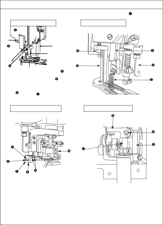
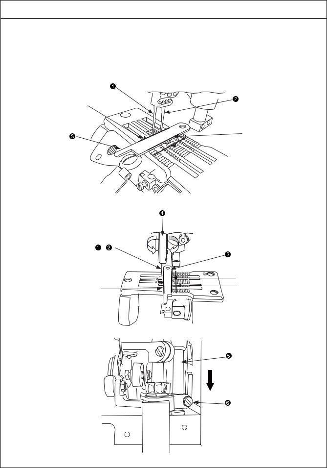
(1) Presser removal work
|
|
Procedures of assembling |
|
1. |
To make the standard adjustments of the flatseamer, remove the presser main body |
first of all. |
|
|
Main body assembly diagram |
State of the presser removed |
|
|
Rear side of the presser main body |
State of the face cover removed |
|
– 8 –
From the library of Superior Sewing Machine & Supply LLC - www.supsew.com

Procedures of assembling
Disassembly procedures for the presser main body
1.Loosen the setscrews  (4 pcs.) and take out the face cover
  .
.
2.Open the protection cover  and take out the needles
  (5 pcs.) with the needle bars
  positioned at the upper dead point.
3.Loosen the upper knife fixing screw  (key wrench of 3/8) and remove the upper knife
  .
.
4.Loosen the setscrews  (2 pcs.) and take out the upper knife fixing block
  and the upper knife auxiliary plate
  .
.
5.Loosen the presser bar setscrew  .
.
6.Loosen the presser guide left setscrews  (key wrench of 5/32) (2 pcs.) and remove the presser guide left setscrews
  on the operator side. Make the presser guide left
  free.
free.
7.Remove the presser pressure adjusting screw  and the pressing screw.
8.Loosen the presser bar guide setscrew  and remove the presser bar guide
  and the presser bar
  while the presser bar
  is pulled out upwards.
9.Remove the presser main body  .
.
– 9 –
From the library of Superior Sewing Machine & Supply LLC - www.supsew.com
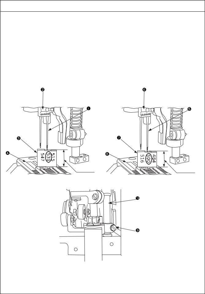
(2) Adjusting the height of the needle bar
Standard Adjustment
oFor a needle gauge of 5.2mm
Mount the right needle  on the needle clamp
  with the needle bar positioned at the upper dead point and put the needle bar height gauge
  on the upper face of the throat plate
  . Check this condition in the position of 531. The standard needle bar height is 13.5mm.
Use the needle bar height gauge (21227BU).
oFor a needle gauge of 6.0mm
Mount the right needle  on the needle clamp
  with the needle bar positioned at the upper dead point and put the needle bar height gauge
  on the upper face of the throat plate
  . Check this condition in the position of 500. The standard needle bar height is 12.7mm.
Use the needle bar height gauge (21227DS).
Needle gauge : 5.2mm |
Needle gauge : 6.0mm |
13.5mm |
12.7mm |
– 10 –
From the library of Superior Sewing Machine & Supply LLC - www.supsew.com

|
Adjustment Procedures |
|
Results of Improper Adjustment |
|
|
|
|||
1. Remove the face cover and loosen the needle bar connecting bracket |
When the needle bar height is |
|||
setscrew to adjust the needle bar height by the means of the needle |
greatly different |
|||
bar height gauge |
or . |
|
|
o This will be a cause of stitch skip- |
(Caution) When checking the needle bar height, change the needles |
ping, needle breakage, or thread |
|||
and |
, enter the needles |
and |
in the needle |
breakage. |
clamps |
and to their uppermost ends, and stop them |
|
||
in the correct positions. The needle shank has a flat sec- |
|
|||
tion. Stop the needle with the flat section positioned in |
|
|||
front. |
|
|
|
|
2. After the adjustment of the needle bar height, adjustment of the needle array is carried out subsequently. Temporarily fasten the setscrew  of the needle bar connecting bracket
  .
.
(Caution) 1. When the needle bar connecting bracket setscrew 
is fastened temporarily, the needle bar is required not to come down even when it is rotated.
2.If the needle bar height is changed for a certain rea-
son, readjustment is needed from the beginning, using the needle bar height gauge  or
or  .
.
– 11 –
From the library of Superior Sewing Machine & Supply LLC - www.supsew.com
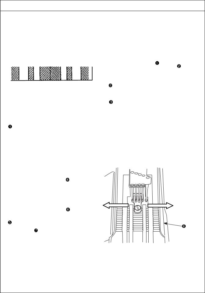
(3) Adjustment of needle array
Standard Adjustment
1.Needle array
Use the left needle  and the retainer needle
  , and check the needle array based on Line A of the upper knife
  .
.
Apply Line A of the upper knife  to the left needle
  and the retainer needle
  on both sides. In this state, the standard angle is that Line B of the upper knife
  is observed in parallel to Line C of the throat plate groove.
A line
B line
 C line
Right and left revolving 
,
|
B line |
A line |
C line |
|
– 12 –
From the library of Superior Sewing Machine & Supply LLC - www.supsew.com

|
Adjustment Procedures |
|
|
Results of Improper Adjustment |
|
|
|
|
|
|
|
Method of needle array check |
|
|
|
When the needle parallelism is not |
|
1. |
Checks on the needle array parallelism are carried out after the |
secured |
|||
|
completion of needle bar height adjustments. |
|
|
o This will be a cause of stitch skip- |
|
2. |
When checking the needle array parallelism, the needle bar |
is |
ping, needle breakage, thread |
||
|
lowered to the midpoint under the condition that no looper is attached. |
breakage, or destruction of throat |
|||
3. |
Make Line A of the upper knife |
come in contact with the left needle |
plate claws. |
||
|
and the retainer needle |
on both sides. In this state, check the |
|
||
|
parallelism between Line B of the upper knife |
and Line C of the |
|
||
|
throat plate groove. |
|
|
|
|
4.If no parallelism is secured, insert a spanner (7mm/9/32) in the needle
clamp  and try to secure the needle array parallelism by turning the needle bar
  to the right and left.
(Caution) If checking is intended without the dislodgment of the looper, do it in the position where the left needle  and the retainer needle
  do not come in contact with the rear side of the looper.
5.After the confirmation of parallelism, check the needle bar height again and fix the needle bar connecting bracket setscrew  .
.
– 13 –
From the library of Superior Sewing Machine & Supply LLC - www.supsew.com
(4) Right and left needle entry position adjustments
Standard Adjustment
1.Needle entry
Attach the needles  (4 pcs.) and the retainer needle
  , and check the right and left needle entry spaces in regard to the throat plate claws
  .
.
Examine the position where the left space becomes wider by 0.15mm than the right space. In this state, the
standard position is that the needles  (4 pcs.) and the retainer needle
  (1 pc.), five needles in all, do not touch the right and left throat plate claws
  .
.
Left space wider by |
Right space |
0.15mm |
|
Left middle needle
regarded as the basis
Throat plate
Right and left revolving directions
Left direction |
Right direction |
– 14 –
From the library of Superior Sewing Machine & Supply LLC - www.supsew.com

|
Adjustment Procedures |
|
Results of Improper Adjustment |
||
|
|
|
|
||
Needle entry adjusting positions |
|
|
When the needle parallelism is not |
||
1. |
When adjusting the right and left needle entry, remove the front top |
secured |
|
||
|
cover and the oil receiver. |
|
|
o This will be a cause of stitch skip- |
|
2. |
Loosen the collar setscrew |
and move the collar |
toward the |
ping, needle breakage, thread |
|
|
front. |
|
|
breakage, or destruction of throat |
|
3. |
Loosen the hexagon coupling bolt and insert a screwdriver in the |
plate claws |
as a result of get- |
||
|
eccentric pin . When the screwdriver is turned to the right and left, |
ting flaws. |
|
||
|
the cylinder arm moves to the right and left. |
|
|
|
|
4.Confirm the result of needle entry position adjustments.
5.After adjustments, tighten the hexagon coupling bolt  to return the
collar |
to its initial position. Since then, tighten the collar setscrew |
. |
|
Method of confirmation
o Turning the eccentric pin  to the right causes the cylinder arm
  to move to the left.
oTurning the eccentric pin  to the left causes the cylinder arm
  to move to the right.
– 15 –
From the library of Superior Sewing Machine & Supply LLC - www.supsew.com
(5) Looper adjustment
Standard Adjustment
1) Returning amount of the looper
When the looper  is positioned at the leftmost point, adjust the distance to 4mm from the tip of the looper
  to the center of the left needle
  .
.
The amount of standard looper return is 4mm. However, the amount of return of the looper  may somewhat change according to the type of thread.
The final amount of return of the looper  should be determined by making fine adjustments of the amount of looper
  return while making threading and observing the stitches of trial sewing.
4mm shall be regarded as the amount of return of the looper  during adjustments.
Right and left directions
Tip
Center
4mm (5/32)
Right and left directions |
Forward and back- |
|
ward directions |
2)Adjustment of a clearance between looper and needle
The standard clearance is 0.0mm (light contact) when the tip of the looper  reaches the center of the left needle
  .
.
After rear needle holder adjustments, check the clearance again between the looper  and the left needle
  . For the final adjustment, this check should be carried out after making threading.
(Caution) 1. If no rear needle holder is provided, the above-mentioned checks should be carried out in the state that the tip of the looper  slightly touches the left needle
  .
.
2.The needles to be used come in two types; with a scoop (118GKS) and without a scoop (118GAS).
Clearance between the looper  and the left needle
0.0mm
(Light contact)
– 16 –
From the library of Superior Sewing Machine & Supply LLC - www.supsew.com
|
|
Adjustment Procedures |
|
|
Results of Improper Adjustment |
||
|
|
|
|
|
|||
1) Returning amount of the looper |
|
|
|
When the amount of looper return, |
|||
1. |
Mount the looper |
on the looper base |
and fasten it with the |
changing with the type of thread, is |
|||
|
setscrew . |
|
|
|
|
too much |
|
2. |
Loosen the looper base setscrew |
and move the looper base |
to |
o Tightness of stitches becomes |
|||
|
the right or left for adjustments. |
|
|
|
worse for the left needle thread |
||
3. |
After adjustments, tighten the looper base setscrew . |
|
and the stitches of thread tension |
||||
(Caution) When making adjustments by moving the looper base |
are degraded. |
|
|||||
|
to the right or left, the forward and backward posi- |
When the amount of return is small |
|||||
|
tioning of the looper base |
is also changed. |
|
o This can be a cause of stitch skip- |
|||
|
During the right-left adjustment of the looper base |
, |
ping when the looper |
is re- |
|||
|
make adjustments of "7.-(5)-2), Adjustment of clearance |
treated. |
|
||||
|
between looper and needle" simultaneously by means |
o The needle thread, second from |
|||||
|
of the setscrew . |
|
|
|
the right needle, is delayed from |
||
|
|
|
|
|
|
the looper and it comes out si- |
|
|
|
|
|
|
|
multaneously with the right needle |
|
|
|
|
|
|
|
thread. Thus, the stitches of thread |
|
|
|
|
|
|
|
tension are degraded. |
|
|
|
|
|
|
|
o This is a cause of second stitch |
|
|
|
|
|
|
|
skipping as seen from the left |
|
|
|
|
|
|
|
needle . |
|
2) Adjustment of a clearance between looper and needle
1.Loosen the looper base setscrew  and turn the setscrew
  to adjust the looper base
  by moving it forward and backward.
2.After adjustments, tighten the looper base setscrew  .
.
o When the looper base  is moved to the left, the tip of the looper
  is separated from the left needle
  .
.
o When the looper base  is moved to the right, the tip of the looper
 comes in contact with the left needle
  .
.
(Caution) After the completion of adjustments in accordance with "7.-(6) Adjustment of looper and needle bar timing" and "7.-(7), 7.-(8) Adjustment of looper movement and motion locus", make readjustments, without fail, according to "2) Adjustment of a clearance between looper and needle".
– 17 –
From the library of Superior Sewing Machine & Supply LLC - www.supsew.com
(6) Adjustment of looper and needle bar timing
Standard Adjustment
1.Looper and needle bar timing (synchronization)
Synchronization is adjusted after mounting the respective gauge parts. Turn the pulley in the forward direction and adjust the tip of the synchro-gauge rod  to the graduation after the needle bar
  has been stopped. The standard position is defined when the pulley is turned in the reverse direction and the tip of the synchro-gauge rod
  stops at the same graduation for forward pulley rotation after the needle bar
  has been stopped.
(Caution) When the pulley is turned in the forward/reverse direction, the standard value is defined if the obtained figure is different by less than 1 from the graduation of the tip of the synchrogauge rod  .
.
Tip of the synchro- |
Forward movement |
|
|
gauge rod |
|
Graduation
Reverse movement
US gauge Part No. 21227CG
Thickness:
4mm
(Caution) Installation of the gauge indicated in the above drawing falls on the new 36200L type. In regard to the installation of the gauge for the former type 36200, installation of the needle bar
torque tool  is not required.
Right and left revolving directions
Forward and backward directions
(Caution) The main shaft coupling front and rear,  and
and  , are provided with the fitting mark
  . Gauge check should be carried out after making adjustments to the fitting mark
  .
.
– 18 –
From the library of Superior Sewing Machine & Supply LLC - www.supsew.com

|
Adjustment Procedures |
|
Results of Improper Adjustment |
|
|
|
|
||
How to mount and use the synchro-adjust gauge |
|
o Incorrect synchro-gauge position- |
||
1. |
Attach the needle bar torque tool to top of the needle bar and |
ing may cause stitch skipping. |
||
|
tighten the setscrew |
. Then, move the needle bar |
to the lower |
|
|
dead point. |
|
|
|
2. |
Mount the gauge base |
on the presser pressure adjusting spring |
|
|
|
and fix the needle bar height adjusting screw |
just above the |
|
|
|
needle bar . |
|
|
|
3.Insert the 4mm-thick portion of the synchro-gauge base  in between the needle bar
  and the needle bar height adjusting screw
 . Turn the needle bar height adjusting screw
  until it comes in contact with the synchro-gauge base
  . In the state that a dimension (thickness) of 4mm is maintained, tighten and fix the needle bar height adjusting nut
  .
.
4.Remove the synchro-gauge base  and mount it on the looper
  . Tighten the setscrew
  . When the pulley is turned in forward direction, the needle bar
  rises by 4mm and stops there. At this time, adjust the tip of the synchro-gauge rod
  to the specified graduation position. (Within the scale range)
5.When the pulley is turned in reverse direction, the needle bar  rises, lowers, and stops. Confirm the graduation position of the tip of the synchro-gauge rod
  . If there is any deviation by more than 1 from the graduation position in forward revolution, adjust the main shaft coupling front and rear,
  and
and  , respectively.
Adjusting positions and method of adjustment
To make timing adjustments for the looper  and the needle bar
  , remove the rear top cover and loosen three nuts
  of the main shaft coupling front and rear,
  and
and  , respectively. In the state that the main shaft coupling rear
  is held, move the main shaft coupling front
  to the right and left to adjust it.
(Spanner 1/4 inches for the nut  )
)
oTurning the main shaft coupling front  to the right causes the tip of the synchro-gauge rod
  to go backward.
o Turning the main shaft coupling front  to the left causes the tip of the synchro-gauge rod
  to go forward.
(Caution) To move the main shaft coupling front  , temporarily fasten a nut that is located near the fitting mark
  during adjustment. If the nut
  is not fastened temporarily, position of the tip of the synchro-gauge rod
  cannot be made stable.
– 19 –
From the library of Superior Sewing Machine & Supply LLC - www.supsew.com
Loading...