

Page 1
R
1910011345
TL-SG3210/TL-SG3216/TL-SG3424/TL-SG3424P
JetStream L2 Managed Switch
EV3.0.1
Page 2

COPYRIGHT & TRADEMARKS
Specifications are subject to change without notice. is a registered trademark of
TP-LINK TECHNOLOGIES CO., LTD. Other brands and product names are trademarks or
registered trademarks of their respective holders.
No part of the specifications may be reproduced in any form or by any means or used to make any
derivative such as translation, transformation, or adaptation without permission from TP-LINK
TECHNOLOGIES CO., LTD. Copyright © 2015 TP-LINK TECHNOLOGIES CO., LTD. All rights
reserved.
http://www.tp-link.com
FCC STATEMENT
This equipment has been tested and found to comply with the limits for a Class A digital device,
pursuant to part 15 of the FCC Rules. These limits are designed to provide reasonable protection
against harmful interference when the equipment is operated in a commercial environment. This
equipment generates, uses, and can radiate radio frequency energy and, if not installed and used
in accordance with the instruction manual, may cause harmful interference to radio
communications. Operation of this equipment in a residential area is likely to cause harmful
interference in which case the user will be required to correct the interference at his own expense.
This device complies with part 15 of the FCC Rules. Operation is subject to the following two
conditions:
1) This device may not cause harmful interference.
2) This device must accept any interference received, including interference that may cause
undesired operation.
Any changes or modifications not expressly approved by the party responsible for compliance
could void the user’s authority to operate the equipment.
CE Mark Warning
This is a Class A product. In a domestic environment, this product may cause radio interference, in
which case the user may be required to take adequate measures.
Продукт сертифіковано згідно с правилами системи УкрСЕПРО на відповідність вимогам
нормативних документів та вимогам, що передбачені чинними законодавчими актами
України.
I
Page 3

Safety Information
When product has power button, the power button is one of the way to shut off the product;
When there is no power button, the only way to completely shut off power is to disconnect the
product or the power adapter from the power source.
Don’t disassemble the product, or make repairs yourself. You run the risk of electric shock and
voiding the limited warranty. If you need service, please contact us.
Avoid water and wet locations.
安全諮詢及注意事項
●請使用原裝電源供應器或只能按照本產品注明的電源類型使用本產品。
●清潔本產品之前請先拔掉電源線。請勿使用液體、噴霧清潔劑或濕布進行清潔。
●注意防潮,請勿將水或其他液體潑灑到本產品上。
●插槽與開口供通風使用,以確保本產品的操作可靠並防止過熱,請勿堵塞或覆蓋開口。
●請勿將本產品置放於靠近熱源的地方。除非有正常的通風,否則不可放在密閉位置中。
●請不要私自打開機殼,不要嘗試自行維修本產品,請由授權的專業人士進行此項工作。
此為甲類資訊技術設備,于居住環境中使用時,可能會造成射頻擾動,在此種情況下,使用者會被
要求採取某些適當的對策。
This product can be used in the following countries:
AT BG BY CA CZ DE DK EE
ES FI FR GB GR HU IE IT
LT LV MT NL NO PL PT RO
RU SE SK TR UA US
II
Page 4

CONTENTS
Package Contents .......................................................................................................................... 1
Chapter 1 About This Guide ......................................................................................................... 2
1.1 Intended Readers ......................................................................................................... 2
1.2 Conventions .................................................................................................................. 2
1.3 Overview of This Guide ................................................................................................ 2
Chapter 2 Introduction .................................................................................................................. 6
2.1 Overview of the Switch ................................................................................................. 6
2.2 Appearance Description ............................................................................................... 6
2.2.1 Front Panel ........................................................................................................ 6
2.2.2 Rear Panel ......................................................................................................... 9
Chapter 3 Login to the Switch ..................................................................................................... 10
3.1 Login ........................................................................................................................... 10
3.2 Configuration .............................................................................................................. 11
Chapter 4 System ....................................................................................................................... 12
4.1 System Info ................................................................................................................. 12
4.1.1 System Summary ............................................................................................. 12
4.1.2 Device Description ........................................................................................... 14
4.1.3 System Time .................................................................................................... 14
4.1.4 Daylight Saving Time ....................................................................................... 15
4.1.5 System IP ......................................................................................................... 17
4.1.6 System IPv6 ..................................................................................................... 18
4.2 User Management ...................................................................................................... 27
4.2.1 User Table ........................................................................................................ 27
4.2.2 User Config ...................................................................................................... 27
4.3 System Tools .............................................................................................................. 29
4.3.1 Config Restore ................................................................................................. 29
4.3.2 Config Backup .................................................................................................. 29
4.3.3 Firmware Upgrade ........................................................................................... 30
4.3.4 System Reboot ................................................................................................ 31
4.3.5 System Reset ................................................................................................... 31
4.4 Access Security .......................................................................................................... 31
4.4.1 Access Control ................................................................................................. 31
III
Page 5

4.4.2 HTTP Config .................................................................................................... 32
4.4.3 HTTPS Config .................................................................................................. 33
4.4.4 SSH Config ...................................................................................................... 36
4.4.5 Telnet Config .................................................................................................... 42
Chapter 5 Switching .................................................................................................................... 43
5.1 Port ............................................................................................................................. 43
5.1.1 Port Config ....................................................................................................... 43
5.1.2 Port Mirror ........................................................................................................ 44
5.1.3 Port Security .................................................................................................... 47
5.1.4 Port Isolation .................................................................................................... 49
5.1.5 Loopback Detection ......................................................................................... 50
5.2 LAG ............................................................................................................................ 51
5.2.1 LAG Table ........................................................................................................ 52
5.2.2 Static LAG ........................................................................................................ 53
5.2.3 LACP Config .................................................................................................... 54
5.3 Traffic Monitor ............................................................................................................. 56
5.3.1 Traffic Summary ............................................................................................... 56
5.3.2 Traffic Statistics ................................................................................................ 57
5.4 MAC Address .............................................................................................................. 59
5.4.1 Address Table .................................................................................................. 60
5.4.2 Static Address .................................................................................................. 61
5.4.3 Dynamic Address ............................................................................................. 62
5.4.4 Filtering Address .............................................................................................. 64
Chapter 6 VLAN .......................................................................................................................... 66
6.1 802.1Q VLAN.............................................................................................................. 67
6.1.1 VLAN Config .................................................................................................... 69
6.1.2 Port Config ....................................................................................................... 71
6.2 MAC VLAN ................................................................................................................. 73
6.3 Protocol VLAN ............................................................................................................ 74
6.3.1 Protocol Group Table ....................................................................................... 77
6.3.2 Protocol Group ................................................................................................. 77
6.3.3 Protocol Template ............................................................................................ 78
6.4 Application Example for 802.1Q VLAN ....................................................................... 80
6.5 Application Example for MAC VLAN ........................................................................... 81
6.6 Application Example for Protocol VLAN ...................................................................... 82
IV
Page 6

6.7 GVRP ......................................................................................................................... 84
Chapter 7 Spanning Tree ............................................................................................................ 88
7.1 STP Config ................................................................................................................. 93
7.1.1 STP Config ....................................................................................................... 93
7.1.2 STP Summary .................................................................................................. 95
7.2 Port Config .................................................................................................................. 96
7.3 MSTP Instance ........................................................................................................... 98
7.3.1 Region Config .................................................................................................. 98
7.3.2 Instance Config ................................................................................................ 99
7.3.3 Instance Port Config....................................................................................... 101
7.4 STP Security ............................................................................................................. 103
7.4.1 Port Protect .................................................................................................... 103
7.4.2 TC Protect ...................................................................................................... 105
7.5 Application Example for STP Function ..................................................................... 105
Chapter 8 Multicast ................................................................................................................... 110
8.1 IGMP Snooping ........................................................................................................ 11 4
8.1.1 Snooping Config ............................................................................................ 116
8.1.2 VLAN Config .................................................................................................. 116
8.1.3 Port Config ..................................................................................................... 118
8.1.4 IP-Range ........................................................................................................ 119
8.1.5 Multicast VLAN .............................................................................................. 120
8.1.6 Static Multicast IP ........................................................................................... 123
8.1.7 Packet Statistics ............................................................................................. 124
8.2 MLD Snooping .......................................................................................................... 126
8.2.1 Global Config ................................................................................................. 127
8.2.2 VLAN Config .................................................................................................. 129
8.2.3 Filter Config .................................................................................................... 131
8.2.4 Port Config ..................................................................................................... 132
8.2.5 Static Multicast ............................................................................................... 132
8.2.6 Querier Config ................................................................................................ 133
8.2.7 Packet Statistics ............................................................................................. 134
8.3 Multicast Table .......................................................................................................... 136
8.3.1 IPv4 Multicast Table ....................................................................................... 136
8.3.2 IPv6 Multicast Table ....................................................................................... 137
V
Page 7

Chapter 9 QoS .......................................................................................................................... 138
9.1 DiffServ ..................................................................................................................... 141
9.1.1 Port Priority .................................................................................................... 141
9.1.2 DSCP Priority ................................................................................................. 142
9.1.3 802.1P/CoS mapping ..................................................................................... 143
9.1.4 Schedule Mode .............................................................................................. 144
9.2 Bandwidth Control .................................................................................................... 145
9.2.1 Rate Limit ....................................................................................................... 145
9.2.2 Storm Control ................................................................................................. 146
9.3 Voice VLAN .............................................................................................................. 148
9.3.1 Global Config ................................................................................................. 150
9.3.2 Port Config ..................................................................................................... 150
9.3.3 OUI Config ..................................................................................................... 152
Chapter 10 PoE .......................................................................................................................... 154
10.1 PoE Config ............................................................................................................... 154
10.1.1 PoE Config ..................................................................................................... 155
10.1.2 PoE Profile ..................................................................................................... 156
10.2 PoE Time-Range ...................................................................................................... 157
10.2.1 Time-Range Summary ................................................................................... 157
10.2.2 PoE Time-Range Create ................................................................................ 158
10.2.3 PoE Holiday Config ........................................................................................ 159
Chapter 11 ACL .......................................................................................................................... 161
11.1 Time-Range .............................................................................................................. 161
11.1.1 Time-Range Summary ................................................................................... 161
11.1.2 Time-Range Create ........................................................................................ 162
11.1.3 Holiday Config ................................................................................................ 163
11.2 ACL Config ............................................................................................................... 163
11.2.1 ACL Summary ................................................................................................ 164
11.2.2 ACL Create .................................................................................................... 164
11.2.3 MAC ACL ....................................................................................................... 165
11.2.4 Standard-IP ACL ............................................................................................ 166
11.2.5 Extend-IP ACL ............................................................................................... 166
11.3 Policy Config ............................................................................................................. 168
11.3.1 Policy Summary ............................................................................................. 168
11.3.2 Policy Create .................................................................................................. 168
VI
Page 8

11.3.3 Action Create ................................................................................................. 169
11.4 Policy Binding ........................................................................................................... 170
11.4.1 Binding Table ................................................................................................. 170
11.4.2 Port Binding ................................................................................................... 171
11.4.3 VLAN Binding ................................................................................................. 171
11.5 Application Example for ACL .................................................................................... 172
Chapter 12 Network Security ...................................................................................................... 175
12.1 IP-MAC Binding ........................................................................................................ 175
12.1.1 Binding Table ................................................................................................. 175
12.1.2 Manual Binding .............................................................................................. 177
12.1.3 ARP Scanning ................................................................................................ 178
12.1.4 DHCP Snooping ............................................................................................. 179
12.2 ARP Inspection ......................................................................................................... 185
12.2.1 ARP Detect .................................................................................................... 189
12.2.2 ARP Defend ................................................................................................... 190
12.2.3 ARP Statistics ................................................................................................ 191
12.3 DoS Defend .............................................................................................................. 192
12.4 802.1X ...................................................................................................................... 194
12.4.1 Global Config ................................................................................................. 198
12.4.2 Port Config ..................................................................................................... 200
12.4.3 Radius Server ................................................................................................ 201
Chapter 13 SNMP ....................................................................................................................... 204
13.1 SNMP Config ............................................................................................................ 206
13.1.1 Global Config ................................................................................................. 206
13.1.2 SNMP View .................................................................................................... 207
13.1.3 SNMP Group .................................................................................................. 208
13.1.4 SNMP User .................................................................................................... 209
13.1.5 SNMP Community.......................................................................................... 2 11
13.2 Notification ................................................................................................................ 213
13.3 RMON ....................................................................................................................... 215
13.3.1 History Control ............................................................................................... 216
13.3.2 Event Config .................................................................................................. 216
13.3.3 Alarm Config .................................................................................................. 217
Chapter 14 Cluster ...................................................................................................................... 220
14.1 NDP .......................................................................................................................... 221
VII
Page 9

14.1.1 Neighbor Info ................................................................................................. 221
14.1.2 NDP Summary ............................................................................................... 222
14.1.3 NDP Config .................................................................................................... 224
14.2 NTDP ........................................................................................................................ 225
14.2.1 Device Table .................................................................................................. 225
14.2.2 NTDP Summary ............................................................................................. 226
14.2.3 NTDP Config .................................................................................................. 228
14.3 Cluster ...................................................................................................................... 229
14.3.1 Cluster Summary ........................................................................................... 229
14.3.2 Cluster Config ................................................................................................ 230
14.4 Application Example for Cluster Function ................................................................. 232
Chapter 15 LLDP ........................................................................................................................ 235
15.1 Basic Config ............................................................................................................. 239
15.1.1 Global Config ................................................................................................. 239
15.1.2 Port Config ..................................................................................................... 240
15.2 Device Info ................................................................................................................ 241
15.2.1 Local Info ....................................................................................................... 241
15.2.2 Neighbor Info ................................................................................................. 242
15.3 Device Statistics ........................................................................................................ 242
15.4 LLDP-MED ............................................................................................................... 244
15.4.1 Global Config ................................................................................................. 245
15.4.2 Port Config ..................................................................................................... 246
15.4.3 Local Info ....................................................................................................... 247
15.4.4 Neighbor Info ................................................................................................. 248
Chapter 16 Maintenance ............................................................................................................ 250
16.1 System Monitor ......................................................................................................... 250
16.1.1 CPU Monitor .................................................................................................. 250
16.1.2 Memory Monitor ............................................................................................. 251
16.2 Log ............................................................................................................................ 251
16.2.1 Log Table ....................................................................................................... 252
16.2.2 Local Log ....................................................................................................... 253
16.2.3 Remote Log ................................................................................................... 253
16.2.4 Backup Log .................................................................................................... 254
16.3 Device Diagnostics ................................................................................................... 255
16.3.1 Cable Test ...................................................................................................... 255
VIII
Page 10

16.4 Network Diagnostics ................................................................................................. 256
16.4.1 Ping ................................................................................................................ 256
16.4.2 Tracert ............................................................................................................ 257
Appendix A: Specifications ......................................................................................................... 258
Appendix B: Load Software Using FTP ...................................................................................... 260
Appendix C: Glossary ................................................................................................................. 263
IX
Page 11

Package Contents
The following items should be found in your box:
One JetStream L2 Managed Switch
One power cord
One console cable
Two mounting brackets and other fittings
Installation Guide
Resource CD for TL-SG3210/TL-SG3216/TL-SG3424/TL-SG3424P switch, including:
• This User Guide
• The CLI Reference Guide
• SNMP Mibs
• 802.1X Client Software and its User Guide
• Other Helpful Information
Note:
Make sure that the package contains the above items. If any of the listed items are damaged or
missing, please contact your distributor.
1
Page 12
Ignoring this type of note might result in a malfunction or damage to the
make better use
Chapter 1 About This Guide
This User Guide contains information for setup and management of TL-SG3210/TL-SG3216/
TL-SG3424/TL-SG3424P JetStream L2 Managed Switch. Please read this guide carefully before
operation.
1.1 Intended Readers
This Guide is intended for network managers familiar with IT concepts and network terminologies.
1.2 Conventions
In this Guide the following conventions are used:
The switch or device mentioned in this Guide stands for TL-SG3210/TL-SG3216/TL-SG3424/
TL-SG3424P JetStream L2 Managed Switch without any explanation.
Tips:
The TL-SG3210/TL-SG3216/TL-SG3424/TL-SG3424P switchs are sharing this User Guide. They
just differ in the number of LED indicators and ports. For simplicity, we will take TL-SG3424 for
example throughout this Guide. However, differences with significance will be presented with
figures or notes as to attract your attention.
Menu Name→Submenu Name→Tab page indicates the menu structure. System→System
Info→System Summary means the System Summary page under the System Info menu
option that is located under the System menu.
Bold font indicates a button, a toolbar icon, menu or menu item.
Symbols in this Guide:
Symbol Description
Note:
Tips:
device.
This format indicates important information that helps you
of your device.
1.3 Overview of This Guide
Chapter Introduction
Chapter 1 About This Guide Introduces the guide structure and conventions.
Chapter 2 Introduction Introduces the features, application and appearance of the switch.
2
Page 13

users to log on to the Web management page with a certain
Provide different security measures for the
propagate the local VLAN registration information to other
f the
Chapter Introduction
Chapter 3 Login to the Switch Introduces how to log on to the Web management page.
Chapter 4 System This module is used to configure system properties of the switch.
Here mainly introduces:
System Info: Configure the description, system time and network
parameters of the switch.
User Management: Configure the user name and password for
access level.
System Tools: Manage the configuration file of the switch.
Access Security:
login to enhance the configuration management security.
Chapter 5 Switching This module is used to configure basic functions of the switch. Here
mainly introduces:
Port: Configure the basic features for the port.
LAG: Configure Link Aggregation Group. LAG is to combine a
number of ports together to make a single high-bandwidth data
path.
Traffic Monitor: Monitor the traffic of each port
MAC Address: Configure the address table of the switch.
Chapter 6 VLAN This module is used to configure VLANs to control broadcast in
LANs. Here mainly introduces:
802.1Q VLAN: Configure port-based VLAN.
MAC VLAN: Configure MAC-based VLAN without changing the
802.1Q VLAN configuration.
Protocol VLAN: Create VLANs in application layer to make some
special data transmitted in the specified VLAN.
GVRP: GVRP allows the switch to automatically add or remove
the VLANs via the dynamic VLAN registration information and
switches, without having to individually configure each VLAN.
Chapter 7 Spanning Tree This module is used to configure spanning tree function o
switch. Here mainly introduces:
STP Config: Configure and view the global settings of spanning
tree function.
Port Config: Configure CIST parameters of ports.
MSTP Instance: Configure MSTP instances.
STP Security: Configure protection function to prevent devices
from any malicious attack against STP features.
Chapter 8 Multicast This module is used to configure multicast function of the switch.
Here mainly introduces:
IGMP Snooping: Configure global parameters of IGMP Snooping
function, port properties, VLAN and multicast VLAN.
MLD Snooping: Configure global parameters of MLD Snooping
function, port properties, VLAN and multicast VLAN.
Multicast Table: View the information of IPv4 and IPv6 multicast
groups already on the switch.
3
Page 14

quality of service for various network applications and
ty, 802.1P priority and
Bandwidth Control: Configure rate limit feature to control the
transmit voice data
stream within the specified VLAN so as to ensure the
ure to prevent DoS
This module is used to configure SNMP function to provide a
e RMON function to monitor network more
Chapter Introduction
Chapter 9 QoS This module is used to configure QoS function to provide different
requirements. Here mainly introduces:
DiffServ: Configure priorities, port priori
DSCP priority.
traffic rate on each port; configure storm control feature to filter
broadcast, multicast and UL frame in the network.
Voice VLAN: Configure voice VLAN to
transmission priority of voice data stream and voice quality.
Chapter 10 PoE This module is used to configure the PoE function for the switch to
supply power for PD devices. Here mainly introduces:
PoE Config: Configure PoE function globally.
PoE Time-Range: Configure the effective time for PoE port to
supply power.
Chapter 11 ACL This module is used to configure match rules and process policies
of packets to filter packets in order to control the access of the
illegal users to the network. Here mainly introduces:
Time-Range: Configure the effective time for ACL rules.
ACL Config: ACL rules.
Policy Config: Configure operation policies.
Policy Binding: Bind the policy to a port/VLAN to take its effect on
a specific port/VLAN.
Chapter 12 Network Security This module is used to configure the multiple protection measures
for the network security. Here mainly introduces:
IP-MAC Binding: Bind the IP address, MAC address, VLAN ID
and the connected Port number of the Host together.
ARP Inspection: Configure ARP inspection feature to prevent the
network from ARP attacks.
DoS Defend: Configure DoS defend feat
attack.
802.1X: Configure common access control mechanism for LAN
ports to solve mainly authentication and security problems.
Chapter 13 SNMP
management frame to monitor and maintain the network devices.
Here mainly introduces:
SNMP Config: Configure global settings of SNMP function.
Notification: Configure notification function for the management
station to monitor and process the events.
RMON: Configur
efficiently.
4
Page 15
Cluster: Configure cluster function to establish and maintain
This module is used to configure LLDP function to provide
Test the connection status of the cable
Introduces how to use 802.1X Client Software provided for
Chapter Introduction
Chapter 14 Cluster This module is used to configure cluster function to central manage
the scattered devices in the network. Here mainly introduces:
NDP: Configure NDP function to get the information of the directly
connected neighbor devices.
NTDP: Configure NTDP function for the commander switch to
collect NDP information.
cluster.
Chapter 15 LLDP
information for SNMP applications to simplify troubleshooting. Here
mainly introduces:
Basic Config: Configure the LLDP parameters of the device.
Device Info: View the LLDP information of the local device and its
neighbors.
Device Statistics: View the LLDP statistics of the local device.
LLDP-MED: Configure LLDP-MED parameters of the device.
Chapter 16 Maintenance This module is used to assemble the commonly used system tools
to manage the switch. Here mainly introduces:
System Monitor: Monitor the memory and CPU of the switch.
Log: View configuration parameters on the switch.
Device Diagnostics:
connected to the switch, test if the port of the switch and the
connected device are available.
Network Diagnostics: Test if the destination is reachable and the
account of router hops from the switch to the destination.
Appendix A Specifications Lists the hardware specifications of the switch.
Appendix B Configure the PCs Introduces how to configure the PCs.
Appendix C Load Software
Introduces how to load firmware of the switch via FTP function.
Using FTP
Appendix D 802.1X Client
Software
authentication.
Appendix E Glossary Lists the glossary used in this manual.
Return to CONTENTS
5
Page 16
Chapter 2 Introduction
Thanks for choosing the TL-SG3210/TL-SG3216/TL-SG3424/TL-SG3424P JetStream L2
Managed Switch!
2.1 Overview of the Switch
Designed for workgroups and departments, TL-SG3210/TL-SG3216/TL-SG3424/TL-SG3424P
from TP-LINK provides wire-speed performance and full set of layer 2 management features. It
provides a variety of service features and multiple powerful functions with high security.
The EIA-standardized framework and smart configuration capacity can provide flexible solutions
for a variable scale of networks. ACL, 802.1x and Dynamic ARP Inspection provide robust security
strategy. QoS and IGMP/MLD snooping optimize voice and video application. Link aggregation
(LACP) increases aggregated bandwidth, optimizing the transport of business critical data.
SNMP/SNMPv6, RMON, WEB/CLI/Telnet Log-in bring abundant management policies.
TL-SG3210/TL-SG3216/TL-SG3424/TL-SG3424P switch integrates multiple functions with
excellent performance, and is friendly to manage, which can fully meet the need of the users
demanding higher networking performance.
2.2 Appearance Description
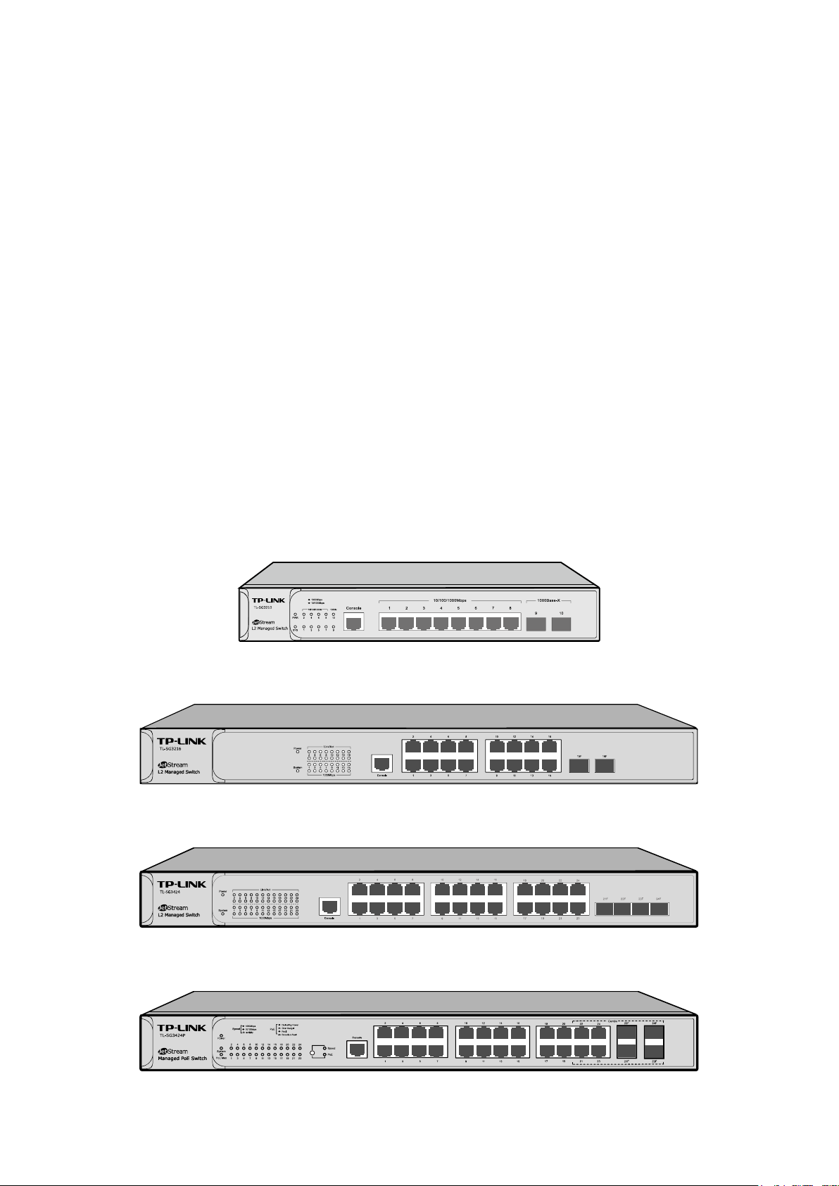
2.2.1 Front Panel
The front panel of TL-SG3210 is shown as the following figure.
Figure 2-1 Front Panel of TL-SG3210
The front panel of TL-SG3216 is shown as the following figure.
Figure 2-2 Front Panel of TL-SG3216
The front panel of TL-SG3424 is shown as the following figure.
Figure 2-3 Front Panel of TL-SG3424
The front panel of TL-SG3424P is shown as the following figure.
Figure 2-4 Front Panel of TL-SG3424P
6
Page 17
A 1000Mbps device is connected to the corresponding
A 10/100Mbps device or no device is connected to the
A device is connected to the corresponding port, but not
The following parts are located on the front panel of the switches:
10/100/1000Mbps Ports: Designed to connect to the device with a bandwidth of 10Mbps,
100Mbps or 1000Mbps. Each has a corresponding 1000Mbps LED. Each port of
TL-SG3216/TL-SG3424 also features a Link/Act LED.
SFP Ports: Designed to install the SFP module. TL-SG3216/TL-SG3424/TL-SG3424P switch
features some SFP transceiver slots that are shared with the associated RJ45 ports. The
associated two ports are referred to as “Combo” ports, which means they cannot be used
simultaneously, otherwise only SFP ports work. TL-SG3210 features two individual SFP ports.
Note:
For TL-SG3216/TL-SG3424/TL-SG3424P switch, when using the SFP port with a 100M module or
a gigabit module, you need to configure its corresponding Speed and Duplex mode on
Switching→Port→Port Config page. For 100M module, please select 100MFD while select
1000MFD for gigabit module. By default, the Speed and Duplex mode of SFP port is 1000MFD.
For TL-SG3210’s SFP port, it only supports 1000MFD mode.
Console Port: Designed to connect with the serial port of a computer or terminal for monitoring
and configuring the switch.
LEDs
For TL-SG3210/TL-SG3216/TL-SG3424:
Name Status Indication
On Power is on.
Power
Flashing Power supply is abnormal.
(PWR)
Off Power is off or power supply is abnormal.
On The switch is working abnormally.
System
Flashing The switch is working normally.
(SYS)
Off The switch is working abnormally.
On
port.
1000Mbps
Link/Act
Off
On
Flashing Data is being transmitted or received.
corresponding port.
activity.
Off No device is connected to the corresponding port.
Note:
There is no Link/Act LED on TL-SG3210.
7
Page 18
A 10/100Mbps device is connected to the
For TL-SG3424P:
TL-SG3424P has a LED mode switch button which is for switching the LED status indication.
When the Speed LED is on, the port LED is indicating the data transmission rate. When the PoE
LED is on, the port LED is indicating the power supply status. By default the Speed LED is on.
Pressing the mode switch button, the Speed LED will turn off and the PoE LED will light up. Then
the PoE LED will turn off after being on for 60 seconds and the Speed LED will light up again.
When the Speed LED is on, the port LED is indicating the data transmission rate.
Name Status Indication
On The switch is powered on.
Power
Off The switch is powered off or power supply is abnormal.
Flashing Power supply is abnormal.
Flashing The switch works properly.
System
On/Off The switch works improperly.
Green
On
A 1000Mbps device is connected to the corresponding
port, but no activity.
Flashing Data is being transmitted or received.
10/100/1000Mbps
Yellow
On
corresponding port, but no activity.
Flashing Data is being transmitted or received.
Off No device is connected to the corresponding port.
When the PoE LED is on, the port LED is indicating the power supply status.
Name Status Indication
On The switch is powered on.
Power
Off The switch is powered off or power supply is abnormal.
Flashing Power supply is abnormal.
System
Flashing The switch works properly.
On/Off The switch works improperly.
On The remaining PoE power≤7W.
PoE Max
Flashing The remaining PoE power keeps ≤7W after this LED is
on for 2 minutes.
Off The remaining PoE power>7W.
On The port is supplying power normally.
Green
Flashing
10/100/1000Mbps
The supply power exceeds the corresponding port’s
maximum power.
Yellow On Overload or short circuit is detected.
Off No PoE power supply is provided on the port.
8
Page 19

2.2.2 Rear Panel
The rear panel of the switch features a power socket and a Grounding Terminal (marked with ).
Figure 2-5 Rear Panel
Grounding Terminal: The switch already comes with Lightning Protection Mechanism. You
can also ground the switch through the PE (Protecting Earth) cable of AC cord or with Ground
Cable.
AC Power Socket: Connect the female connector of the power cord here, and the male
connector to the AC power outlet. Make sure the voltage of the power supply meets the
requirement of the input voltage (100-240V~ 50/60Hz 0.6A for TL-SG3210, 100-240V~ 50/60Hz 0.4A
TL-SG3216, 100-240V~ 50/60Hz 0.5A TL-SG3424 and 100-240V~ 50/60Hz 5A for TL-SG3424P).
Return to CONTENTS
9
Page 20
Chapter 3 Login to the Switch
3.1 Login
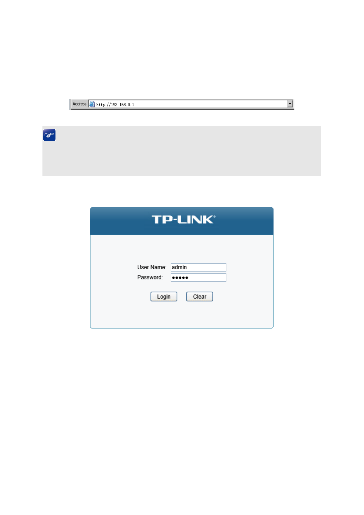
1) To access the configuration utility, open a web-browser and type in the default address
http://192.168.0.1 in the address field of the browser, then press the Enter key.
Figure 3-1 Web-browser
Tips:
To log in to the switch, the IP address of your PC should be set in the same subnet addresses of
the switch. The IP address is 192.168.0.x ("x" is any number from 2 to 254), Subnet Mask is
255.255.255.0. For the detailed instructions as to how to do this, please refer to Appendix B.
2) After a moment, a login window will appear, as shown in Figure 3-2. Enter admin for the User
Name and Password, both in lower case letters. Then click the Login button or press the
Enter key.
Figure 3-2 Login
10
Page 21
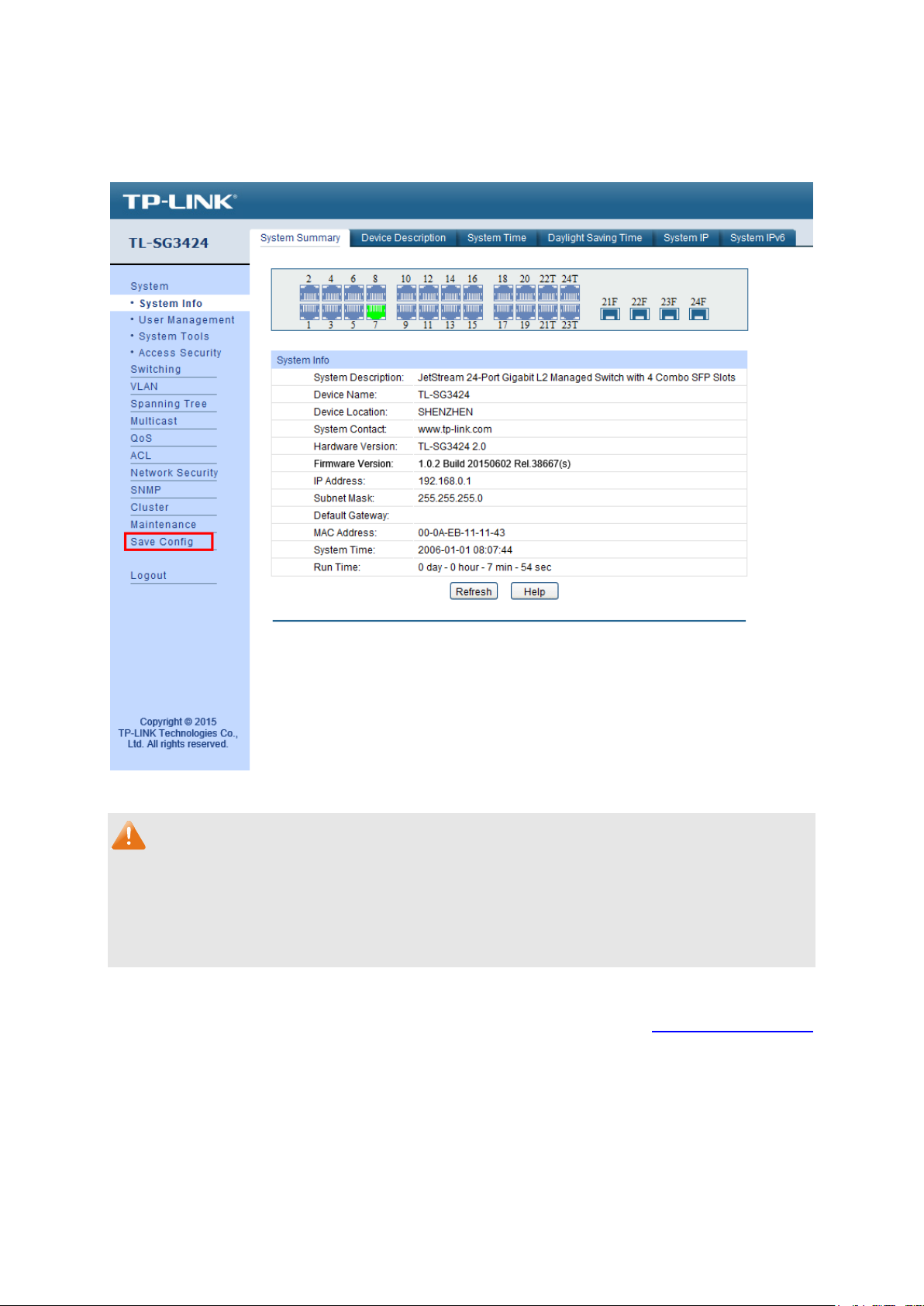
3.2 Configuration
After a successful login, the main page will appear as Figure 3-3, and you can configure the
function by clicking the setup menu on the left side of the screen.
Figure 3-3 Main Setup-Menu
Note:
Clicking Apply can only make the new configurations effective before the switch is rebooted. If
you want to keep the configurations effective even the switch is rebooted, please click Save
Config. You are suggested to click Save Config before cutting off the power or rebooting the
switch to avoid losing the new configurations.
Return to CONTENTS
11
Page 22
Chapter 4 System
The System module is mainly for system configuration of the switch, including four submenus:
System Info, User Management, System Tools and Access Security.
4.1 System Info
The System Info, mainly for basic properties configuration, can be implemented on System
Summary, Device Description, System Time, Daylight Saving Time, System IP and System
IPv6 pages.
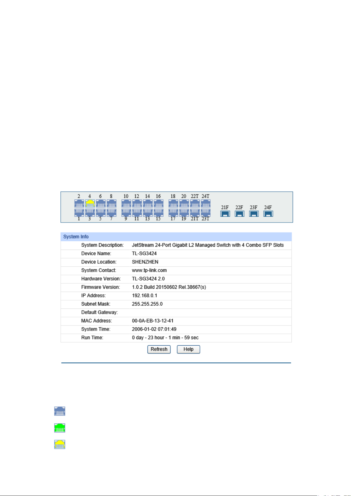
4.1.1 System Summary
On this page you can view the port connection status and the system information.
The port status diagram shows the working status of 24 10/100/1000Mbps RJ45 ports and 4 SFP
ports of the switch. Ports 1-20 and ports 21T-24T are 10/100/1000Mbps ports and ports 21T-24T
are Combo ports with SFP ports labeled as 21F-24F.
Choose the menu System →System Info →System Summary to load the following page.
Figure 4-1 System Summary
The following entries are displayed on this screen:
Port Status
Indicates the 1000Mbps port is not connected to a device.
Indicates the 1000Mbps port is at the speed of 1000Mbps.
Indicates the 1000Mbps port is at the speed of 10Mbps or 100Mbps.
12
Page 23
Select Rx to display the bandwidth utilization of receiving packets
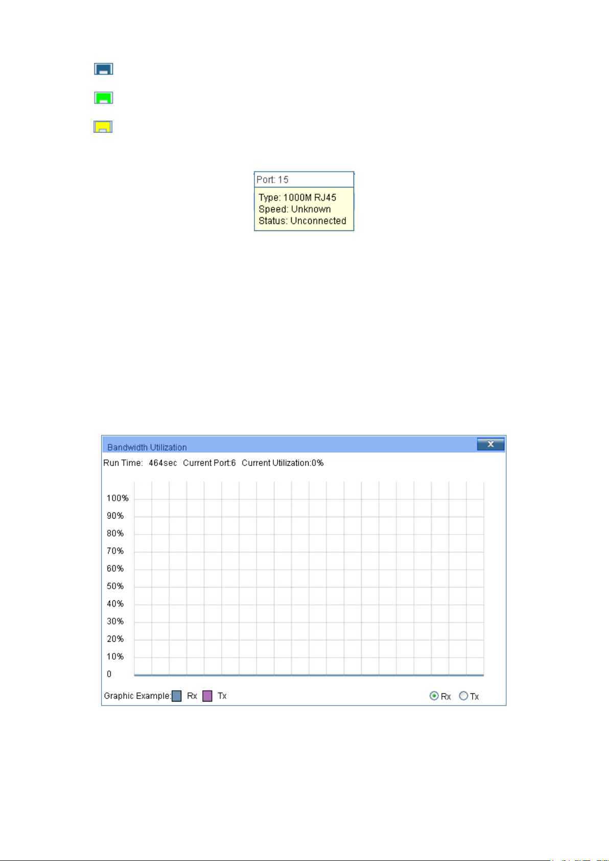
Indicates the SFP port is not connected to a device.
Indicates the SFP port is at the speed of 1000Mbps.
Indicates the SFP port is at the speed of 100Mbps.
When the cursor moves on the port, the detailed information of the port will be displayed.
Figure 4-2 Port Information
Port Info
Port: Displays the port number of the switch.
Typ e : Displays the type of the port.
Speed: Displays the maximum transmission rate of the port.
Status: Displays the connection status of the port.
Click a port to display the bandwidth utilization on this port. The actual rate divided by theoretical
maximum rate is the bandwidth utilization. The following figure displays the bandwidth utilization
monitored every four seconds. Monitoring the bandwidth utilization on each port facilitates you to
monitor the network traffic and analyze the network abnormities.
Figure 4-3 Bandwidth Utilization
Bandwidth Utilization
Rx:
on this port.
13
Page 24
Select Tx to display the bandwidth utilization of sending packets
Tx:
on this port.
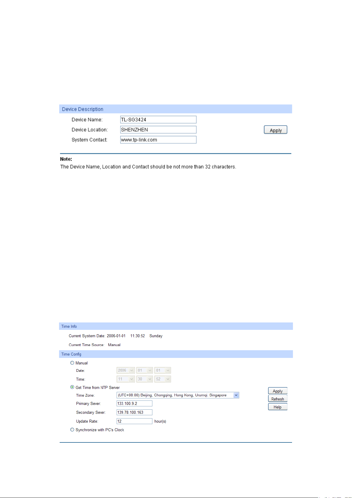
4.1.2 Device Description
On this page you can configure the description of the switch, including device name, device location
and system contact.
Choose the menu System →System Info →Device Description to load the following page.
Figure 4-4 Device Description
The following entries are displayed on this screen:
Device Description
Device Name: Enter the name of the switch.
Device Location: Enter the location of the switch.
System Contact: Enter your contact information.
4.1.3 System Time
System Time is the time displayed while the switch is running. On this page you can configure the
system time and the settings here will be used for other time-based functions like ACL.
You can manually set the system time, get time from NTP server automatically if it has connected to
an NTP server or synchronize with PC’s clock as the system time.
Choose the menu System →System Info →System Time to load the following page.
Figure 4-5 System Time
14
Page 25

date and time
P
and
from
ter the IP Address for the
Synchronize with
clock is
The following entries are displayed on this screen:
Time Info
Current System
Displays the current date and time of the switch.
Date:
Current Time
Displays the current time Source of the switch.
Source:
Time Config
Manual: When this option is selected, you can set the
manually.
Get time from NT
Server:
When this option is selected, you can configure the time zone
the IP Address for the NTP server. The switch will get time
NTP server automatically if it has connected to an NTP server.
Time Zone: Select your local time.
Primary/Secondary NTP Server: En
NTP server.
Update Rate: Specify the rate fetching time from NTP server.
When this option is selected, the administrator PC’s
PC’S Clock:
utilized.
Note:
1. The system time will be restored to the default when the switch is restarted and you need to
reconfigure the system time of the switch.
2. When Get time from NTP Server is selected and no time server is configured, the switch will
get time from the time server of the Internet if it has connected to the Internet.
4.1.4 Daylight Saving Time
Here you can configure the Daylight Saving Time of the switch.
15
Page 26
Sunday in
Australia: First Sunday in October, 02:00 ~ First Sunday in
: Last Sunday in March, 01:00 ~ Last Sunday in
st
Specify the DST configuration in recurring mode. This
Offset: Specify the time adding in minutes when Daylight
Start/End Time: Select starting time and ending time of
Specify the DST configuration in Date mode. This configuration is
Offset: Specify the time adding in minutes when Daylight
Start/End Time: Select starting time and ending time of
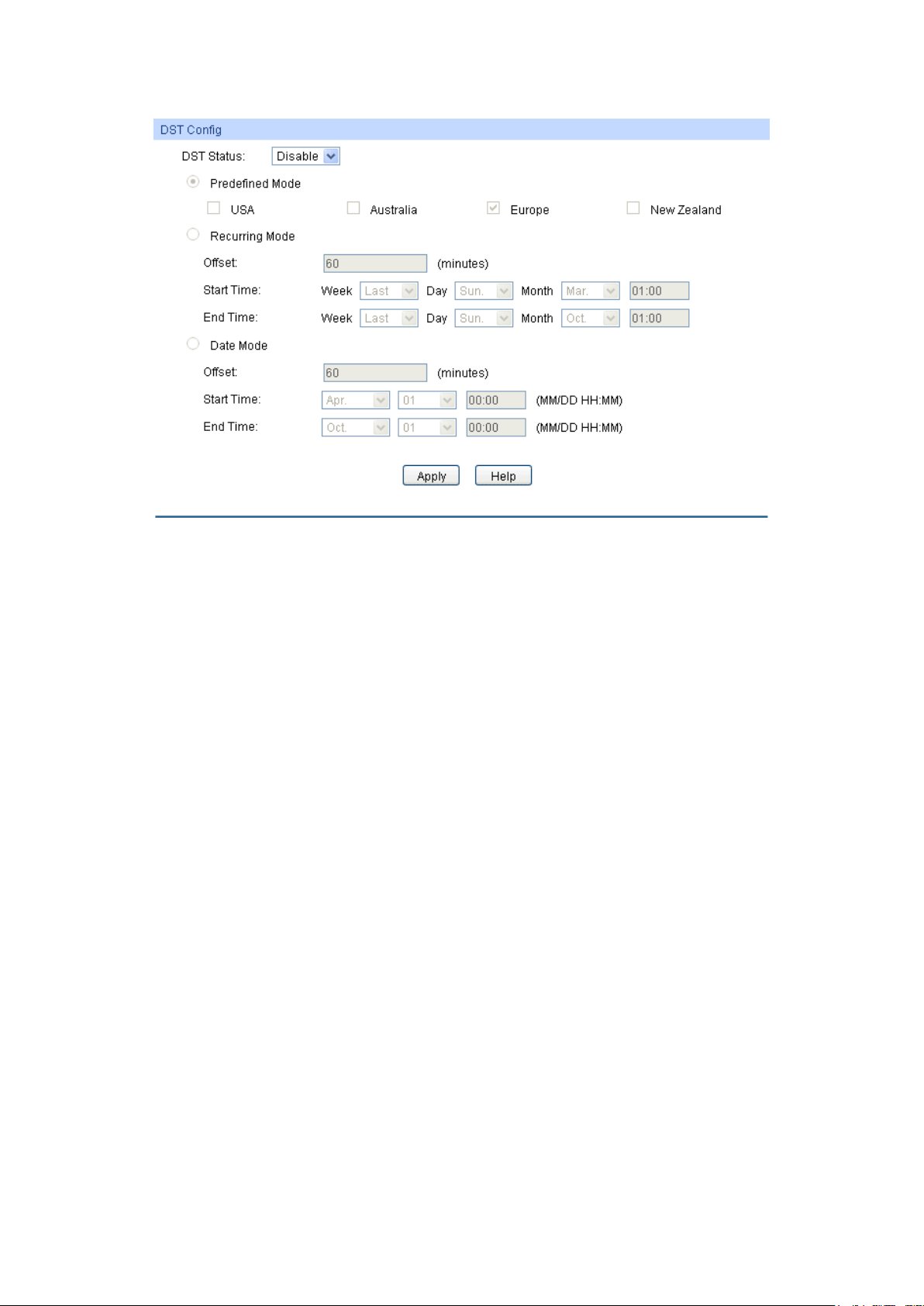
Choose the menu System →System Info →Daylight Saving Time to load the following page.
Figure 4-6 Daylight Saving Time
The following entries are displayed on this screen:
DST Config
DST Status: Enable or disable the DST.
Predefined Mode: Select a predefined DST configuration:
USA: Second Sunday in March, 02:00 ~ First
November, 02:00.
April, 03:00.
Europe
October, 01:00.
New Zealand: Last Sunday in September, 02:00 ~ Fir
Sunday in April, 03:00.
Recurring Mode:
configuration is recurring in use.
Saving Time comes.
Daylight Saving Time.
Date Mode:
one-off in use.
Saving Time comes.
Daylight Saving Time.
16
Page 27
Static IP: When this option is selected, you should enter IP
DHCP: When this option is selected, the switch will obtain
BOOTP: When this option is selected, the switch will obtain
Enter the system IP of the switch. The default system IP is
Note:
1. When the DST is disabled, the predefined mode, recurring mode and date mode cannot be
configured.
2. When the DST is enabled, the default daylight saving time is of Europe in predefined mode.
4.1.5 System IP
Each device in the network possesses a unique IP Address. You can log on to the Web
management page to operate the switch using this IP Address. The switch supports three modes
to obtain an IP address: Static IP, DHCP and BOOTP. The IP address obtained using a new mode
will replace the original IP address. On this page you can configure the system IP of the switch.
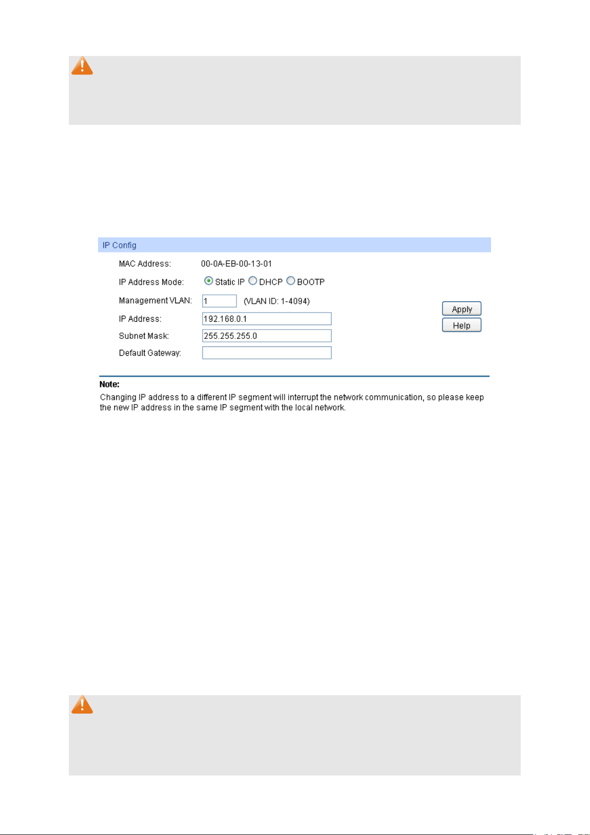
Choose the menu System →System Info →System IP to load the following page.
Figure 4-7 System IP
The following entries are displayed on this screen:
IP Config
MAC Address: Displays MAC Address of the switch.
IP Address Mode: Select the mode to obtain IP Address for the switch.
Address, Subnet Mask and Default Gateway manually.
network parameters from the DHCP Server.
network parameters from the BOOTP Server.
IP Address:
192.168.0.1 and you can change it appropriate to your needs.
Subnet Mask: Enter the subnet mask of the switch.
Default Gateway: Enter the default gateway of the switch.
Note:
1. Changing the IP address to a different IP segment will interrupt the network communication,
so please keep the new IP address in the same IP segment with the local network.
2. The switch only possesses an IP address. The IP address configured will replace the original
IP address.
17
Page 28

3. If the switch gets the IP address from DHCP server, you can see the configuration of the
switch in the DHCP server; if DHCP option is selected but no DHCP server exists in the
network, a few minutes later, the switch will restore the setting to the default.
4. If DHCP or BOOTP option is selected, the switch will get network parameters dynamically
from the Internet, which means that its IP address, subnet mask and default gateway cannot
be configured.
5. The default IP address is 192.168.0.1.
4.1.6 System IPv6
IPv6 (Internet Protocol version 6), also called IPng (IP next generation), was developed by the
IETF (Internet Engineering Task Force) as the successor to IPv4 (Internet Protocol version 4).
Compared with IPv4, IPv6 increases the IP address size from 32 bits to 128 bits; this solves the
IPv4 address exhaustion problem.
IPv6 features
IPv6 has the following features:
1. Adequate address space: The source and destination IPv6 addresses are both 128 bits (16
bytes) long. IPv6 can provide 3.4 x 10
hierarchical address division as well as allocation of public and private addresses.
38
addresses to completely meet the requirements of
2. Header format simplification: IPv6 cuts down some IPv4 header fields or move them to IPv6
extension headers to reduce the load of basic IPv6 headers, thus making IPv6 packet handling
simple and improving the forwarding efficiency. Although the IPv6 address size is four times
that of IPv4 addresses, the size of basic IPv6 headers is 40 bytes and is only twice that of IPv4
headers (excluding the Options field).
3. Flexible extension headers: IPv6 cancels the Options field in IPv4 packets but introduces
multiple extension headers. In this way, IPv6 enhances the flexibility greatly to provide
scalability for IP while improving the handling efficiency. The Options field in IPv4 packets
contains 40 bytes at most, while the size of IPv6 extension headers is restricted by that of IPv6
packets.
4. Built-in security: IPv6 uses IPSec as its standard extension header to provide end-to-end
security. This feature provides a standard for network security solutions and improves the
interoperability between different IPv6 applications.
5. Automatic address configuration: To simplify the host configuration, IPv6 supports stateful
and stateless address configuration.
Stateful address configuration means that a host acquires an IPv6 address and related
information from a server (for example, DHCP server).
Stateless address configuration means that a host automatically configures an IPv6
address and related information on basis of its own link-layer address and the prefix
information advertised by a router.
In addition, a host can generate a link-local address on basis of its own link-layer address and
the default prefix (FE80::/64) to communicate with other hosts on the link.
18
Page 29

6. Enhanced neighbor discovery mechanism: The IPv6 neighbor discovery protocol is a
group of Internet control message protocol version 6 (ICMPv6) messages that manages the
information exchange between neighbor nodes on the same link. The group of ICMPv6
messages takes the place of Address Resolution Protocol (ARP) message, Internet Control
Message Protocol version 4 (ICMPv4) router discovery message, and ICMPv4 redirection
message to provide a series of other functions.
Introduction to IPv6 address
1. IPv6 address format
An IPv6 address is represented as a series of 16-bit hexadecimals, separated by colons (:).
An IPv6 address is divided into eight groups, and the 16 bits of each group are represented by
four hexadecimal numbers which are separated by colons, for example,
2001:0d02:0000:0000:0014: 0000:0000:0095. The hexadecimal letters in IPv6 addresses are
not case-sensitive.
To simplify the representation of IPv6 addresses, zeros in IPv6 addresses can be handled as
follows:
Leading zeros in each group can be removed. For example, the above-mentioned address
can be represented in shorter format as 2001:d02:0:0:14:0:0:95.
Two colons (::) may be used to compress successive hexadecimal fields of zeros at the
beginning, middle, or end of an IPv6 address. For example, the above-mentioned address
can be represented in the shortest format as 2001:d02::14:0:0:95.
Note:
Two colons (::) can be used only once in an IPv6 address, usually to represent the longest
successive hexadecimal fields of zeros. If two colons are used more than once, the device is
unable to determine how many zeros double-colons represent when converting them to zeros to
restore a 128-bit IPv6 address.
An IPv6 address consists of two parts: address prefix and interface ID. The address prefix and
the interface ID are respectively equivalent to the network ID and the host ID in an IPv4
address.
An IPv6 address prefix is represented in "IPv6 address/prefix length" format, where "IPv6
address" is an IPv6 address in any of the above-mentioned formats and "prefix length" is a
decimal number indicating how many leftmost bits from the preceding IPv6 address are used
as the address prefix.
2. IPv6 address classification
IPv6 addresses fall into three types: unicast address, multicast address, and anycast address.
Unicast address: An identifier for a single interface, on a single node. A packet that is sent
to a unicast address is delivered to the interface identified by that address.
19
Page 30

Anycast addresses are taken from unicast
e and are not syntactically
Multicast address: An identifier for a set of interfaces (typically belonging to different nodes),
similar to an IPv4 multicast address. A packet sent to a multicast address is delivered to all
interfaces identified by that address. There are no broadcast addresses in IPv6. Their
function is superseded by multicast addresses.
Anycast address: An identifier for a set of interfaces (typically belonging to different nodes).
A packet sent to an anycast address is delivered to one of the interfaces identified by that
address (the nearest one, according to the routing protocols’ measure of distance).
The type of an IPv6 address is designated by the first several bits called format prefix. The
following table lists the mappings between address types and format prefixes.
Type Format Prefix (binary) IPv6 Prefix ID
Unassigned address 00…0 (128 bits) ::/128
Loopback address 00…1 (128 bits) ::1/128
Unicast
Link-local address 1111111010 FE80::/10
address
Site-local address 1111111011 FEC0::/10
Global unicast address
(currently assigned)
Reserved type
(to be assigned in future)
001 2xxx::/4 or 3xxx::/4
Other formats
Multicast address 11111111 FF00::/8
Anycast address
address spac
distinguishable from unicast addresses.
Table 4-1 Mappings between address types and format prefixes
3. IPv6 Unicast Address:
IPv6 unicast address is an identifier for a single interface. It consists of a subnet prefix and an
interface ID.
Subnet Prefix: This section is allocated by the IANA (The Internet Assigned Numbers
Authority), the ISP (Internet Service Provider) or the organizations.
Interface ID: An interface ID is used to identify interfaces on a link. The interface ID must be
unique to the link.
There are several ways to form interface IDs. The IPv6 addresses with format prefixes 001
through 111, except for multicast addresses (1111 1111), are all required to have 64-bit
interface IDs in EUI-64 format.
20
Page 31

For all IEEE 802 interface types (for example, Ethernet and FDDI interfaces), Interface IDs in
the modified EUI-64 format are constructed in the following way:
The first three octets (24 bits) are taken from the Organizationally Unique Identifier (OUI) of the
48-bit link-layer address (the MAC address) of the interface, the fourth and fifth octets (16 bits)
are a fixed hexadecimal value of FFFE, and the last three octets (24 bits) are taken from the
last three octets of the MAC address. The construction of the interface ID is completed by
setting the universal/local (U/L) bit--the seventh bit of the first octet--to a value of 0 or 1. A
value of 0 indicates a locally administered identifier; a value of 1 indicates a globally unique
IPv6 interface identifier.
Tak e MAC address 0012:0B0A:2D51 as an example. Insert FFFE to the middle of the address
to get 0012:0BFF:FE0A:2D51. Then set the U/L bit to 1 to obtain an interface ID in EUI-64
format as 0212:0BFF:FE0A:2D51.
IPv6 unicast address can be classified into several types, as shown in Table 4-1. The two
most common types are introduced below:
Global unicast address
A Global unicast address is an IPv6 unicast address that is globally unique and is routable on
the global Internet.
Global unicast addresses are defined by a global routing prefix, a subnet ID, and an interface
ID. The IPv6 global unicast address starts with binary value 001 (2000::/3). The global routing
prefix is a value assigned to a site (a cluster of subnets/links) by IANA. The subnet ID is an
identifier of a subnet within the site.
The figure below shows the structure of a global unicast address.
Figure 4-8 Global Unicast Address Format
Link-local address
A link-local address is an IPv6 unicast address that can be automatically configured on any
interface using the link-local prefix FE80::/10 (1111 1110 10) and the interface identifier in the
modified EUI-64 format. Link-local addresses are used in the neighbor discovery protocol and
the stateless autoconfiguration process. Nodes on a local link can use link-local addresses to
communicate. The figure below shows the structure of a link-local address.
21
Page 32
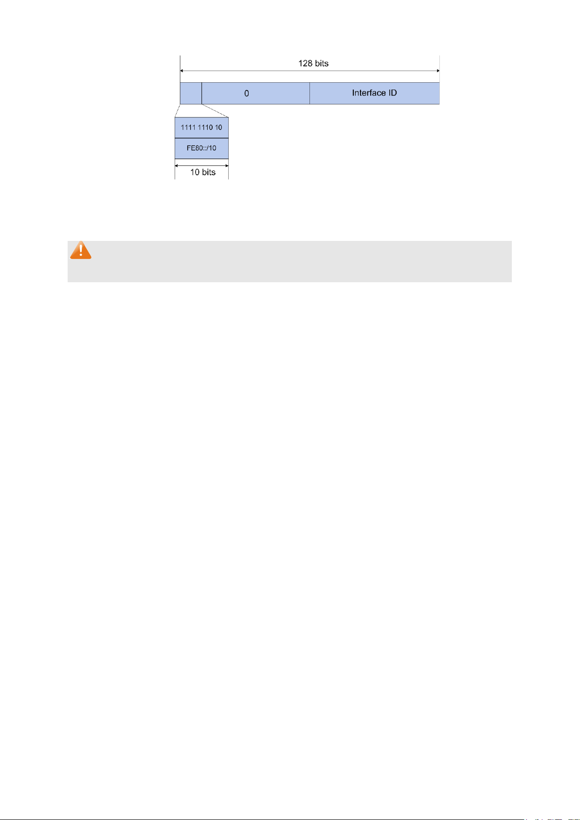
Figure 4-9 Link-local Address Format
IPv6 devices must not forward packets that have link-local source or destination addresses to
other links.
Note:
You can configure multiple IPv6 addresses per interface, but only one link-local address.
IPv6 Neighbor Discovery
The IPv6 neighbor discovery process uses ICMP messages and solicited-node multicast
addresses to determine the link-layer address of a neighbor on the same network (local link),
verify the reachability of a neighbor, and track neighboring devices.
1. IPv6 Neighbor Solicitation Message and Neighbor Advertisement Message
A value of 135 in the Type field of the ICMP packet header identifies a neighbor solicitation
(NS) message. Neighbor solicitation messages are sent on the local link when a node wants
to determine the link-layer address of another node on the same local link.
After receiving the neighbor solicitation message, the destination node replies by sending a
neighbor advertisement (NA) message, which has a value of 136 in the Type field of the ICMP
packet header, on the local link. After the source node receives the neighbor advertisement,
the source node and destination node can communicate.
Neighbor advertisement messages are also sent when there is a change in the link-layer
address of a node on a local link.
Address Resolution
The address resolution procedure is as follows:
Node A multicasts an NS message. The source address of the NS message is the IPv6
address of an interface of node A and the destination address is the solicited-node multicast
address of node B. The NS message contains the link-layer address of node A.
After receiving the NS message, node B judges whether the destination address of the
packet corresponds to the solicited-node multicast address. If yes, node B can learn the
link-layer address of node A, and unicasts an NA message containing its link-layer address.
Node A acquires the link-layer address of node B from the NA message.
22
Page 33

Neighbor Reachability Detection
After node A acquires the link-layer address of its neighbor node B, node A can verify whether
node B is reachable according to NS and NA messages.
Node A sends an NS message whose destination address is the IPv6 address of node B.
If node A receives an NA message from node B, node A considers that node B is reachable.
Otherwise, node B is unreachable.
Duplicate Address Detection
Neighbor solicitation messages are used in the stateless autoconfiguration process to verify
the uniqueness of unicast IPv6 addresses before the addresses are assigned to an interface.
After node A acquires an IPv6 address, it will perform duplicate address detection (DAD) to
determine whether the address is being used by other nodes (similar to the gratuitous ARP
function of IPv4). DAD is accomplished through NS and NA messages. The DAD procedure is
as follows:
Node A sends an NS message whose source address is the unassigned address :: and
destination address is the corresponding solicited-node multicast address of the IPv6
address to be detected. The NS message contains the IPv6 address.
If node B uses this IPv6 address, node B returns an NA message. The NA message
contains the IPv6 address of node B.
Node A learns that the IPv6 address is being used by node B after receiving the NA
message from node B. Otherwise, node B is not using the IPv6 address and node A can
use it.
2. IPv6 Router Advertisement Message
Router advertisement (RA) messages, which have a value of 134 in the Type field of the ICMP
packet header, are periodically sent out each configured interface of an IPv6 router.
RA messages typically include the following information:
One or more onlink IPv6 prefixes that nodes on the local link can use to automatically
configure their IPv6 addresses.
Lifetime information for each prefix included in the advertisement.
Sets of flags that indicate the type of autoconfiguration (stateless or stateful) that can be
completed.
Default router information (whether the device sending the advertisement should be used
as a default router and, if so, the amount of time, in seconds, the device should be used as
a default router).
Additional information for hosts, such as the hop limit and maximum transmission unit (MTU)
a host should use in packets that it originates.
23
Page 34

RAs are also sent in response to device solicitation messages. Device solicitation messages,
which have a value of 133 in the Type field of the ICMP packet header, are sent by hosts at
system startup or anytime needed so that the host can immediately autoconfigure without
needing to wait for the next scheduled RA message.
Hosts discover and select default devices by listening to Router Advertisements (RAs).
Stateless address autoconfiguration means that the node automatically configures an IPv6
address and other information for its interface according to the address prefix and other
configuration parameters in the received RA messages.
3. IPv6 Neighbor Redirect Message
A value of 137 in the type field of the ICMP packet header identifies an IPv6 neighbor redirect
message. Devices send neighbor redirect messages to inform hosts of better first-hop nodes
on the path to a destination.
A device will send an IPv6 ICMP redirect message when the following conditions are satisfied:
The receiving interface is the forwarding interface.
The selected route itself is not created or modified by an IPv6 ICMP redirect message.
The selected route is not the default route.
The forwarded IPv6 packet does not contain any routing header.
24
Page 35

When this option is selected, you should assign a
the switch will generate a
You can configure the system’s administrative IPv6 address on this page.
Choose the menu System →System Info →System IPv6 to load the following page.
Figure 4-10 System IPv6
The following entries are displayed on this screen:
Global Config
IPv6: Enable/Disable IPv6 function globally on the switch.
Link-local Address Config
Config Mode: Select the link-local address configuration mode.
Manual:
link-local address manually.
Auto: When this option is selected,
link-local address automatically.
Link-local Address: Enter a link-local address.
25
Page 36

local address may be newly
l address is duplicate. It is
illegal to access the switch using the IPv6 address(including
configuration via RA
switch automatically configures a
global address and other information according to the address
prefix and other configuration parameters from the received
the system will try to obtain the
You can select the global address format according to your
Indicates that you only need to specify an address
prefix, and then the system will create a global address
Indicates that you have to specify an intact global
ease input the address
Select the desired entry to delete or modify the corresponding
Indicates that the corresponding address is
Indicates that the corresponding address is created
using the RA message or obtained from the
Status: Displays the status of the link-local address.
Normal: Indicates that the link-local address is normal.
Try: Indicates that the link-
configured.
Repeat: Indicates that the link-loca
link-local and global address).
Global Address Autoconfig via RA Message
Enable global
When this option is enabled, the
address auto
message:
Global Address Autoconfig via DHCPv6 Server
Enable Global
Address Autoconfig
RA(Router Advertisement) message.
When this option is enabled,
global address from the DHCPv6 Server.
via DHCPv6 Server:
Add a global address manually
Address Format:
requirements.
EUI-64:
automatically.
Not EUI-64:
address.
Global Address: When selecting the mode of EUI-64, pl
prefix here, otherwise, please input an intact IPv6 address here.
Global address Table
Select:
global address.
Global Address: Modify the global address.
Prefix Length: Modify the prefix length of the global address.
Typ e : Displays the configuration mode of the global address.
Manual:
configured manually.
Auto:
automatically
DHCPv6 Server.
Preferred
Displays the preferred time and valid time of the global address.
Lifetime/Valid
Lifetime:
26
Page 37
Indicates that the global address may be newly
Indicates that the corresponding address is duplicate.
Status: Displays the status of the global address.
Normal: Indicates that the global address is normal.
Try:
configured.
Repeat:
It is illegal to access the switch using this address.
Tips:
After adding a global IPv6 address to your switch manually here, you can configure your PC’s
global IPv6 address in the same subnet with the switch and login to the switch via its global IPv6
address.
4.2 User Management
User Management functions to configure the user name and password for users to log on to the
Web management page with a certain access level so as to protect the settings of the switch from
being randomly changed.
The User Management function can be implemented on User Table and User Config pages.
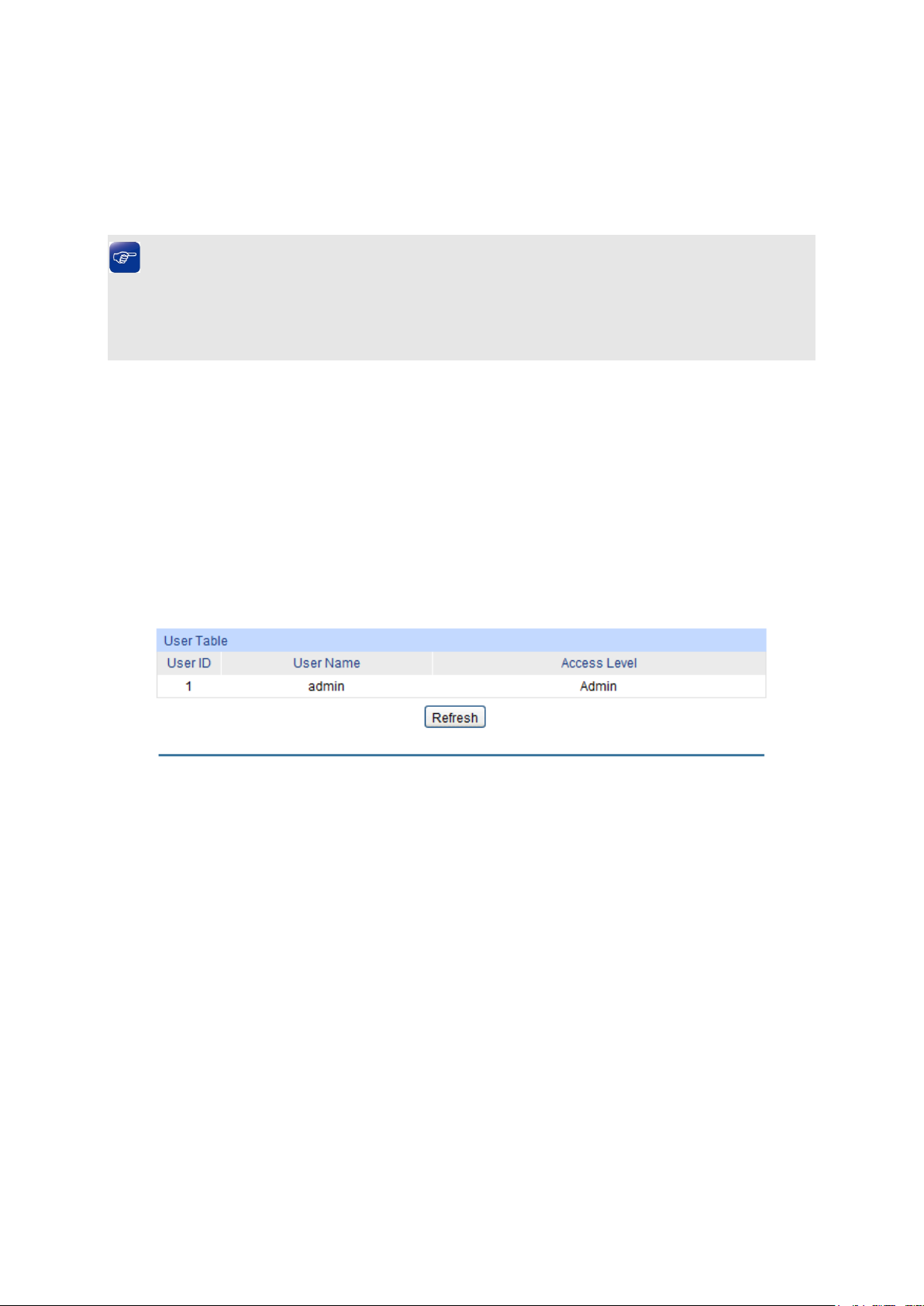
4.2.1 User Table
On this page you can view the information about the current users of the switch.
Choose the menu System →User Management →User Table to load the following page.
Figure 4-11 User Table
4.2.2 User Config
On this page you can configure the access level of the user to log on to the Web management
page. The switch provides two access levels: Guest and Admin. The guest only can view the
settings without the right to configure the switch; the admin can configure all the functions of the
switch. The Web management pages contained in this guide are subject to the admin’s login
without any explanation.
27
Page 38

Admin: Admin can edit, modify and view all the settings of
Select the desired entry to delete the corresponding user
and user
button of the desired entry, and you can edit the
corresponding user information. After modifying the settings,
button to make the modification effective.
the current user information
Choose the menu System →User Management →User Config to load the following page.
Figure 4-12 User Config
The following entries are displayed on this screen:
User Info
User Name: Create a name for users’ login.
Access Level: Select the access level to login.
different functions.
Guest: Guest only can view the settings without the right to edit
and modify.
Password: Type a password for users’ login.
Confirm Password: Retype the password.
User Table
Select:
information. It is multi-optional The current user information cannot
be deleted.
User ID, Name,
Access Level:
Displays the current user ID, user name, access level
status.
Operation: Click the Edit
please click the Modify
Access level and user status of
cannot be modified.
28
Page 39

button to restore the backup
configuration file. It will take effect after the switch automatically
4.3 System Tools
The System Tools function, allowing you to manage the configuration file of the switch, can be
implemented on Config Restore, Config Backup, Firmware Upgrade, System Reboot and
System Reset pages.
4.3.1 Config Restore
On this page you can upload a backup configuration file to restore your switch to this previous
configuration.
Choose the menu System →System Tools →Config Restore to load the following page.
Figure 4-13 Config Restore
The following entries are displayed on this screen:
Config Restore
Restore Config: Click the Restore Config
reboots.
Note:
1. It will take a few minutes to restore the configuration. Please wait without any operation.
2. To avoid any damage, please do not power down the switch while it’s being restored.
3. After being restored, the current settings of the switch will be lost. Wrong uploaded
configuration file may cause the switch unmanaged.
4.3.2 Config Backup
On this page you can download the current configuration and save it as a file to your computer for
your future configuration restore.
29
Page 40

button to save the current configuration
your computer. You are suggested to take this measure
Choose the menu System →System Tools →Config Backup to load the following page.
Figure 4-14 Config Backup
The following entries are displayed on this screen:
Config Backup
Backup Config: Click the Backup Config
as a file to
before upgrading.
Note:
It will take a few minutes to backup the configuration. Please wait without any operation.
4.3.3 Firmware Upgrade
The switch system can be upgraded via the Web management page. To upgrade the system is to
get more functions and better performance. Go to http:// www.tp-link.com to download the updated
firmware.
Choose the menu System →System Tools →Firmware Upgrade to load the following page.
Figure 4-15 Firmware Upgrade
Note:
1. Do not interrupt the upgrade.
2. Please select the proper software version matching with your hardware to upgrade.
3. To avoid damage, please do not turn off the device while upgrading.
4. After upgrading, the device will reboot automatically.
5. You are suggested to backup the configuration before upgrading.
30
Page 41

4.3.4 System Reboot
On this page you can reboot the switch and return to the login page. Please save the current
configuration before rebooting to avoid losing the configuration unsaved
Choose the menu System →System Tools →System Reboot to load the following page.
Figure 4-16 System Reboot
Note:
To avoid damage, please do not turn off the device while rebooting.
4.3.5 System Reset
On this page you can reset the switch to the default. All the settings will be cleared after the switch
is reset.
Choose the menu System →System Tools →System Reset to load the following page.
Figure 4-17 System Reset
Note:
After the system is reset, the switch will be reset to the default and all the settings will be cleared.
4.4 Access Security
Access Security provides different security measures for the remote login so as to enhance the
configuration management security. It can be implemented on Access Control, HTTP Config,
HTTPS Config, SSH Config and Telnet Config pages.
4.4.1 Access Control
On this page you can control the users logging on to the Web management page to enhance the
configuration management security. The definitions of Admin and Guest refer to
Management.
31
4.2 User
Page 42

Select the control mode for users to log on to the Web
range of the users for
he
Choose the menu System →Access Security →Access Control to load the following page.
Figure 4-18 Access Control
The following entries are displayed on this screen:
Access Control Config
Control Mode:
management page.
IP-based: Select this option to limit the IP-
login.
MAC-based: Select this option to limit the MAC Address of t
users for login.
Port-based: Select this option to limit the ports for login.
Access Interface: Select the interface for access control to apply.
IP Address & Mask
These fields is available to configure only when IP-based mode is
selected. Only the users within the IP-range you set here are
allowed for login.
MAC Address: The field is available to configure only when MAC-based mode is
selected. Only the user with this MAC Address you set here are
allowed for login.
Port: The field is available to configure only when Port-based mode is
selected. Only the users connecting to the ports selected are
allowed to manage the switch.
4.4.2 HTTP Config
With the help of HTTP (Hyper Text Transfer Protocol), you can manage the switch through a
standard browser. The standards development of HTTP was coordinated by the Internet
Engineering Task Force and the World Wide Web Consortium.
On this page you can configure the HTTP function.
Choose the menu System→Access Security→HTTP Config to load the following page.
32
Page 43
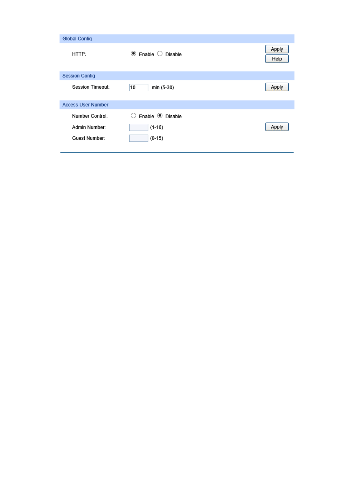
Figure 4-19 HTTP Config
ement page within the
timeout time, the system will log out automatically. If you want to
users logging on to the Web
Enter the maximum number of the users logging on to the Web
The following entries are displayed on this screen:
Global Config
HTTP:
Session Config
Session Timeout:
Select Enable/Disable the HTTP function on the switch.
If you do nothing with the Web manag
reconfigure, please login again.
Access User Number
Number Control:
Admin Number:
Select Enable/Disable the Number Control function.
Enter the maximum number of the
management page as Admin.
Guest Number:
management page as Guest.
4.4.3 HTTPS Config
SSL (Secure Sockets Layer), a security protocol, is to provide a secure connection for the
application layer protocol (e.g. HTTP) communication based on TCP. SSL is widely used to secure
the data transmission between the Web browser and servers. It is mainly applied through
ecommerce and online banking.
SSL mainly provides the following services:
1. Authenticate the users and the servers based on the certificates to ensure the data are
transmitted to the correct users and servers;
2. Encrypt the data transmission to prevent the data being intercepted;
3. Maintain the integrality of the data to prevent the data being altered in the transmission.
Adopting asymmetrical encryption technology, SSL uses key pair to encrypt/decrypt information. A
key pair refers to a public key (contained in the certificate) and its corresponding private key. By
33
Page 44
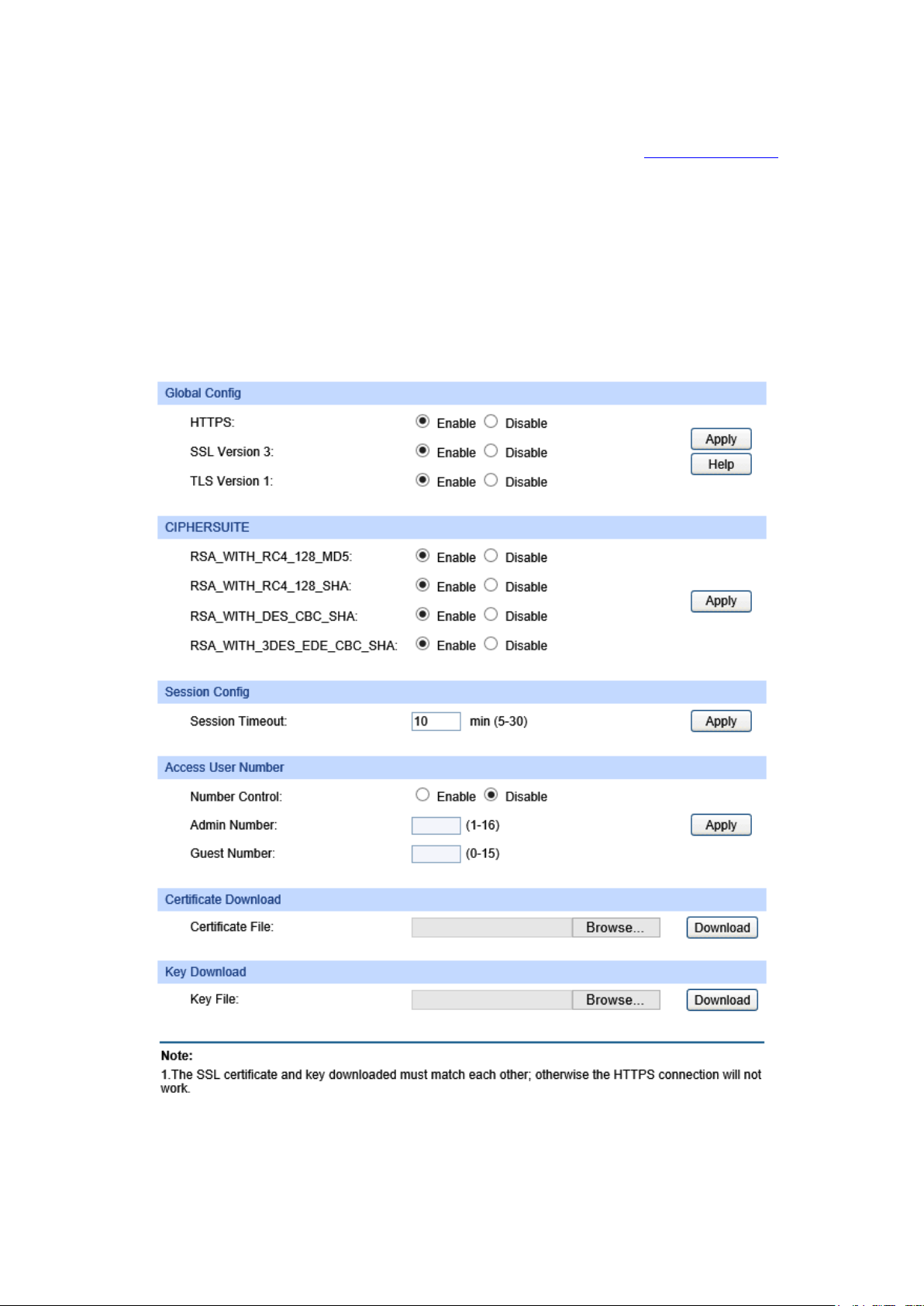
default the switch has a certificate (self-signed certificate) and a corresponding private key. The
Certificate/Key Download function enables the user to replace the default key pair.
After SSL is effective, you can log on to the Web management page via https://192.168.0.1
. For
the first time you use HTTPS connection to log into the switch with the default certificate, you will
be prompted that “The security certificate presented by this website was not issued by a trusted
certificate authority” or “Certificate Errors”. Please add this certificate to trusted certificates or
continue to this website.
The switch also supports HTTPS connection for IPv6. After configuring an IPv6 address (for
example, 3001::1) for the switch, you can log on to the switch’s Web management page via
https://[3001::1].
On this page you can configure the HTTPS function.
Choose the menu System → Access Security → HTTPS Config to load the following page.
Figure 4-20 HTTPS Config
34
Page 45

By
Secure Sockets Layer Version 3.0. By
Transport Layer Security Version 1.0.
MD5 for
SHA for
y. If you want
Enter the maximum number of the users logging on to the
the maximum number of the users logging on to the
Select the desired certificate to download to the switch. The
esired Key to download to the switch. The key
The following entries are displayed on this screen:
Global Config
HTTPS: Enable or Disable the HTTPS function on the switch.
default, it’s enabled.
SSL Version 3:
Enable or Disable the
default, it’s enabled.
TLS Version 1: Enable or Disable the
By default, it’s enabled.
CIPHERSUITE
RSA_WITH_RC4_128_MD5: Key exchange with RC4 128-bit encryption and
message digest. By default, it’s enabled.
RSA_WITH_RC4_128_SHA: Key exchange with RC4 128-bit encryption and
message digest. By default, it’s enabled.
RSA_WITH_DES_CBC_SHA:
Key exchange with DES-CBC for message encryption and
SHA for message digest. By default, it’s enabled.
RSA_WITH_3DES_EDE_CBC
_SHA:
Key exchange with 3DES and DES-EDE3-CBC for message
encryption and SHA for message digest. By default, it’s
enabled.
Session Config
Session Timeout: If you do nothing with the Web management page within the
timeout time, the system will log out automaticall
to reconfigure, please login again.
Access User Number
Number Control: Enable or Disable the Number Control function.
Admin Number:
Web management page as Admin.
Guest Number: Enter
Web management page as Guest.
Certificate Download
Certificate File:
certificate must be BASE64 encoded.
Key Download
Key File: Select the d
must be BASE64 encoded.
35
Page 46

Note:
1. The SSL certificate and key downloaded must match each other; otherwise the HTTPS
connection will not work.
2. To establish a secured connection using https, please enter https:// into the URL field of the
browser.
3. It may take more time for https connection than that for http connection, because https
connection involves authentication, encryption and decryption etc.
4.4.4 SSH Config
As stipulated by IETF (Internet Engineering Task Force), SSH (Secure Shell) is a security protocol
established on application and transport layers. SSH-encrypted-connection is similar to a telnet
connection, but essentially the old telnet remote management method is not safe, because the
password and data transmitted with plain-text can be easily intercepted. SSH can provide
information security and powerful authentication when you log on to the switch remotely through
an insecure network environment. It can encrypt all the transmission data and prevent the
information in a remote management being leaked.
Comprising server and client, SSH has two versions, V1 and V2 which are not compatible with
each other. In the communication, SSH server and client can auto-negotiate the SSH version and
the encryption algorithm. After getting a successful negotiation, the client sends authentication
request to the server for login, and then the two can communicate with each other after successful
authentication. This switch supports SSH server and you can log on to the switch via SSH
connection using SSH client software.
SSH key can be downloaded into the switch. If the key is successfully downloaded, the certificate
authentication will be preferred for SSH access to the switch.
Choose the menu System → Access Security → SSH Config to load the following page.
36
Page 47
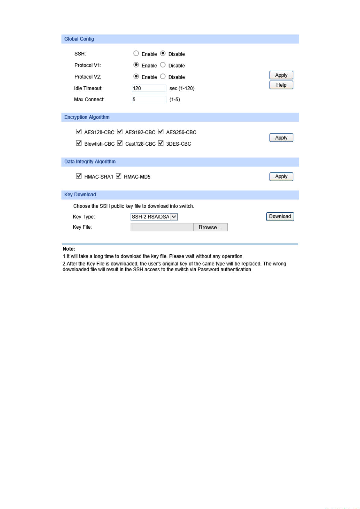
Specify the idle timeout time. The system will automatically
he time is up. The default time is
Specify the maximum number of the connections to the SSH
server. No new connection will be established when the number of
the connections reaches the maximum number you set. The
Figure 4-21 SSH Config
The following entries are displayed on this screen:
Global Config
SSH: Enable or Disable the SSH function. By default, it’s disabled.
Protocol V1: Enable or Disable the SSH V1 to be the supported protocol.
Protocol V2: Enable or Disable the SSH V2 to be the supported protocol.
Idle Timeout:
release the connection when t
120 seconds.
Max Connect:
default value is 5.
Encryption Algorithm
Check the box to enable the corresponding encryption algorithm.
Data Integrity Algorithm
Check the box to enable the corresponding data integrity algorithm.
37
Page 48

the desired key file to the
Key Download
Key Type: Select the type of SSH Key to download. The switch supports two
types: SSH-2 RSA/DSA and SSH-1 RSA.
Key File: Please ensure the key length of the downloaded file is in the range
of 512 to 3072 bits.
Download: Click the Download button to download
switch.
Note:
It will take a long time to download the key file. Please wait without any operation.
Application Example 1 for SSH:
Network Requirements
1. Log on to the switch via password authentication using SSH and the SSH function is enabled
on the switch.
2. PuTTY client software is recommended.
Configuration Procedure
1. Open the software to log on to the interface of PuTTY. Enter the IP address of the switch into
Host Name field; keep the default value 22 in the Port field; select SSH as the Connection
type.
38
Page 49

2. Click the Open button in the above figure to log on to the switch. Enter the login user name and
password, and then you can continue to configure the switch.
Application Example 2 for SSH:
Network Requirements
1. Log on to the switch via password authentication using SSH and the SSH function is enabled
on the switch.
2. PuTTY client software is recommended.
Configuration Procedure
1. Select the key type and key length, and generate SSH key.
Note:
1. The key length is in the range of 512 to 3072 bits.
2. During the key generation, randomly moving the mouse quickly can accelerate the key
generation.
39
Page 50

2. After the key is successfully generated, please save the public key and private key to the
computer.
3. On the Web management page of the switch, download the public key file saved in the
computer to the switch.
Note:
1. The key type should accord with the type of the key file.
2. The SSH key downloading cannot be interrupted.
40
Page 51

4. After the public key is downloaded, please log on to the interface of PuTTY and enter the IP
address for login.
5. Click Browse to download the private key file to SSH client software and click Open.
41
Page 52
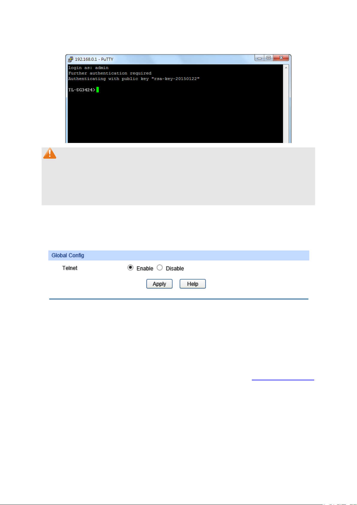
After successful authentication, please enter the login user name. If you log on to the switch
without entering password, it indicates that the key has been successfully downloaded.
Note:
Following the steps above, you have already entered the User EXEC Mode of the switch. However,
to configure the switch, you need a password to enter the Privileged EXEC Mode first. For a switch
with factory settings, the Privileged EXEC Mode password can only be configured through the
console connection. For how to configure the Privileged EXEC Mode password, please refer to the
1.1.2 Configuring the Privileged EXEC Mode Password in CLI Reference Guide.
4.4.5 Telnet Config
On this page you can Enable/Disable Telnet function globally on the switch.
Choose the menu System→Access Security→Telnet Config to load the following page.
Figure 4-22 Telnet Config
The following entries are displayed on this screen:
Global Config
Telnet:
Enable or Disable the Telnet function globally on the switch.
Return to CONTENTS
42
Page 53

Port Select
t
Select
Chapter 5 Switching
Switching module is used to configure the basic functions of the switch, including four submenus:
Port, LAG, Traffic Monitor and MAC Address.
5.1 Port
The Port function, allowing you to configure the basic features for the port, is implemented on the
Port Config, Port Mirror, Port Security, Port Isolation and Loopback Detection pages.
5.1.1 Port Config
On this page, you can configure the basic parameters for the ports. When the port is disabled, the
packets on the port will be discarded. Disabling the port which is vacant for a long time can reduce
the power consumption effectively. And you can enable the port when it is in need.
The parameters will affect the working mode of the port, please set the parameters appropriate to
your needs.
Choose the menu Switching → Port → Port Config to load the following page.
Figure 5-1 Port Config
Here you can view and configure the port parameters.
Port Config
: Click the Select button to quick-select the corresponding por
based on the port number you entered.
: Select the desired port for configuration. It is multi-optional.
43
Page 54

Port
Description
Status
rt. When Enable is
Speed and Duplex
Select the Speed and Duplex mode for the port. The device
connected to the switch should be in the same Speed and
ed, the
Speed and Duplex mode will be determined by
does not support
Flow Control
Allows you to Enable/Disable the Flow Control feature. When
ronize the speed
LAG
: Displays the port number.
: Give a description to the port for identification.
: Allows you to Enable/Disable the po
selected, the port can forward the packets normally.
:
Duplex mode with the switch. When “Auto” is select
auto-negotiation. For the SFP port, this switch
auto-negotiation.
:
Flow Control is enabled, the switch can synch
with its peer to avoid the packet loss caused by congestion.
: Displays the LAG number which the port belongs to.
Note:
1. The switch cannot be managed through the disabled port. Please enable the port which is
used to manage the switch.
2. The parameters of the port members in a LAG should be set as the same.
3. When using the SFP port with a 100M module or a gigabit module, you need to configure its
corresponding Speed and Duplex mode. For 100M module, please select 100MFD while
select 1000MFD for gigabit module. By default, the Speed and Duplex mode of SFP port is
1000MFD.
5.1.2 Port Mirror
Port Mirror, the packets obtaining technology, functions to forward copies of packets from
one/multiple ports (mirrored port) to a specific port (mirroring port). Usually, the mirroring port is
connected to a data diagnose device, which is used to analyze the mirrored packets for monitoring
and troubleshooting the network.
44
Page 55

Choose the menu Switching → Port → Port Mirror to load the following page.
Figure 5-2 Mirror Group List
The following entries are displayed on this screen.
Mirror Group List
Group: Displays the mirror group number.
Mirroring: Displays the mirroring port number.
Mode: Displays the mirror mode, the value will be "Ingress" or "Egress".
Mirrored Port: Displays the mirrored ports.
Operation: Click Edit to configure the mirror group.
45
Page 56

Click Edit to display the following figure.
select the corresponding port
Figure 5-3 Port Mirror Config
The following entries are displayed on this screen.
Mirror Group
Number: Select the mirror group number you want to configure.
Mirroring Port
Mirroring Port: Select the mirroring port number.
Mirrored Port
Port Select: Click the Select button to quick-
based on the port number you entered.
Select: Select the desired port as a mirrored port. It is multi-optional.
Port: Displays the port number.
Ingress: Select Enable/Disable the Ingress feature. When the Ingress is
enabled, the incoming packets received by the mirrored port will
be copied to the mirroring port.
46
Page 57

be selected as the mirrored port or mirroring
Egress: Select Enable/Disable the Egress feature. When the Egress is
enabled, the outgoing packets sent by the mirrored port will be
copied to the mirroring port.
LAG:
Note:
1. The LAG member cannot be selected as the mirrored port or mirroring port.
2. A port cannot be set as the mirrored port and the mirroring port simultaneously.
3. The Port Mirror function can span the multiple VLANs.
Displays the LAG number which the port belongs to. The LAG
member cannot
port.
5.1.3 Port Security
MAC Address Table maintains the mapping relationship between the port and the MAC address of
the connected device, which is the base of the packet forwarding. The capacity of MAC Address
Table is fixed. MAC Address Attack is the attack method that the attacker takes to obtain the
network information illegally. The attacker uses tools to generate the cheating MAC address and
quickly occupy the MAC Address Table. When the MAC Address Table is full, the switch will
broadcast the packets to all the ports. At this moment, the attacker can obtain the network
information via various sniffers and attacks. When the MAC Address Table is full, the packets
traffic will flood to all the ports, which results in overload, lower speed, packets drop and even
breakdown of the system.
Port Security is to protect the switch from the malicious MAC Address Attack by limiting the
maximum number of MAC addresses that can be learned on the port. The port with Port Security
feature enabled will learn the MAC address dynamically. When the learned MAC address number
reaches the maximum, the port will stop learning. Thereafter, the other devices with the MAC
address unlearned cannot access to the network via this port.
47
Page 58
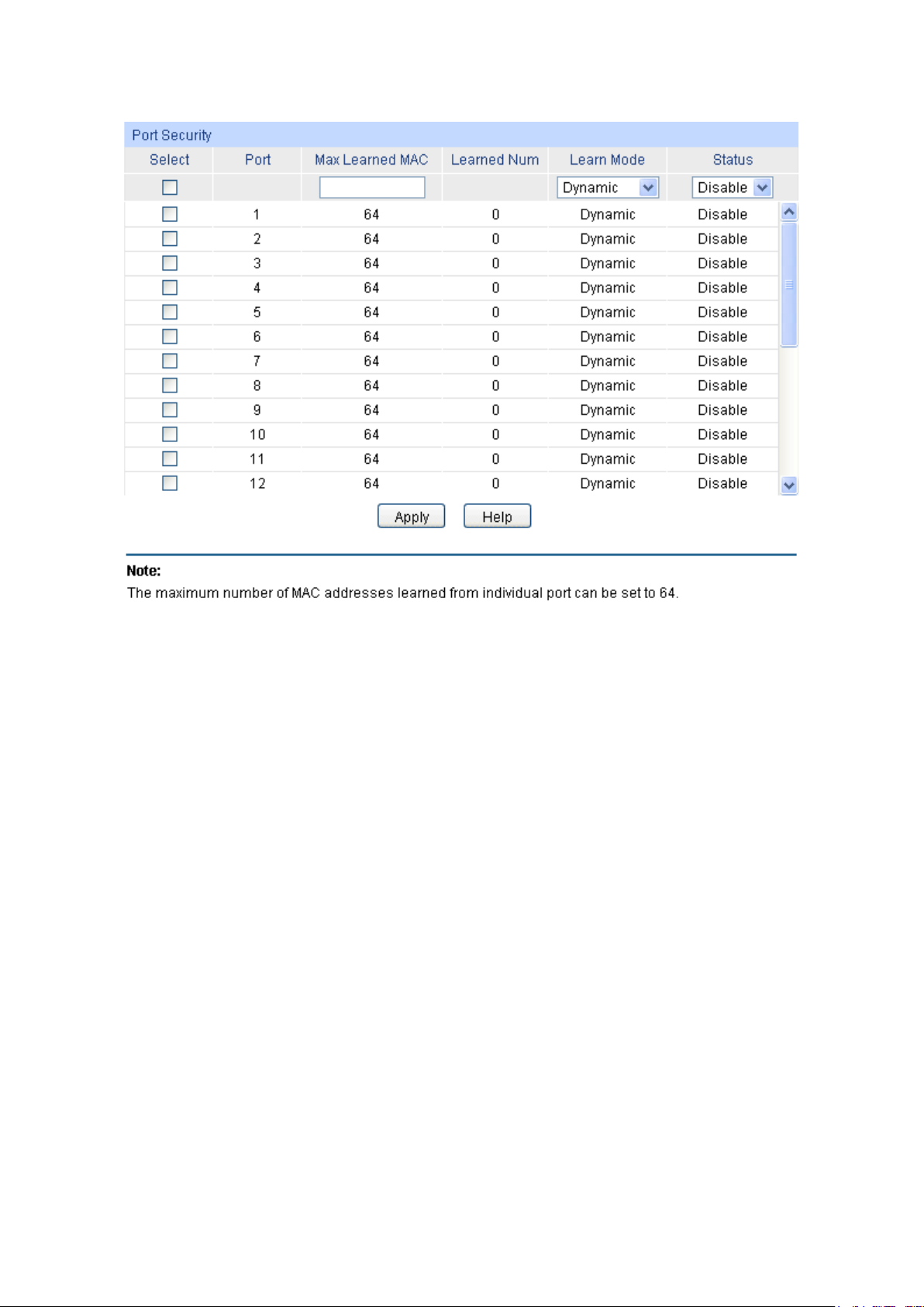
Select
Port
Max Learned MAC
Learned Num
Learn Mode
Status
Choose the menu Switching → Port → Port Security to load the following page.
Figure 5-4 Port Security
The following entries are displayed on this screen:
Port Security
: Select the desired port for Port Security configuration. It is
multi-optional.
: Displays the port number.
: Specify the maximum number of MAC addresses that can be
learned on the port.
: Displays the number of MAC addresses that have been learned
on the port.
: Select the Learn Mode for the port.
• Dynamic: When Dynamic mode is selected, the learned
MAC address will be deleted automatically after the aging
time.
• Static: When Static mode is selected, the learned MAC
address will be out of the influence of the aging time and
can only be deleted manually. The learned entries will be
cleared after the switch is rebooted.
• Permanent: When Permanent mode is selected, the
learned MAC address will be out of the influence of the
aging time and can only be deleted manually. The learned
entries will be saved even the switch is rebooted.
: Select Enable/Disable the Port Security feature for the port.
48
Page 59

Note:
1. The Port Security function is disabled for the LAG port member. Only the port is removed from
the LAG, will the Port Security function be available for the port.
2. The Port Security function is disabled when the 802.1X function is enabled.
5.1.4 Port Isolation
Port Isolation provides a method of restricting traffic flow to improve the network security by
forbidding the port to forward packets to the ports that are not on its forward portlist.
Choose the menu Switching → Port → Port Isolation to load the following page.
Figure 5-5 Port Isolation Config
The following entries are displayed on this screen:
Port Isolation Config
From/To Port: Select the port number range to set its Forward Portlist.
Forward Portlist: Select the ports to be forwarded to.
49
Page 60
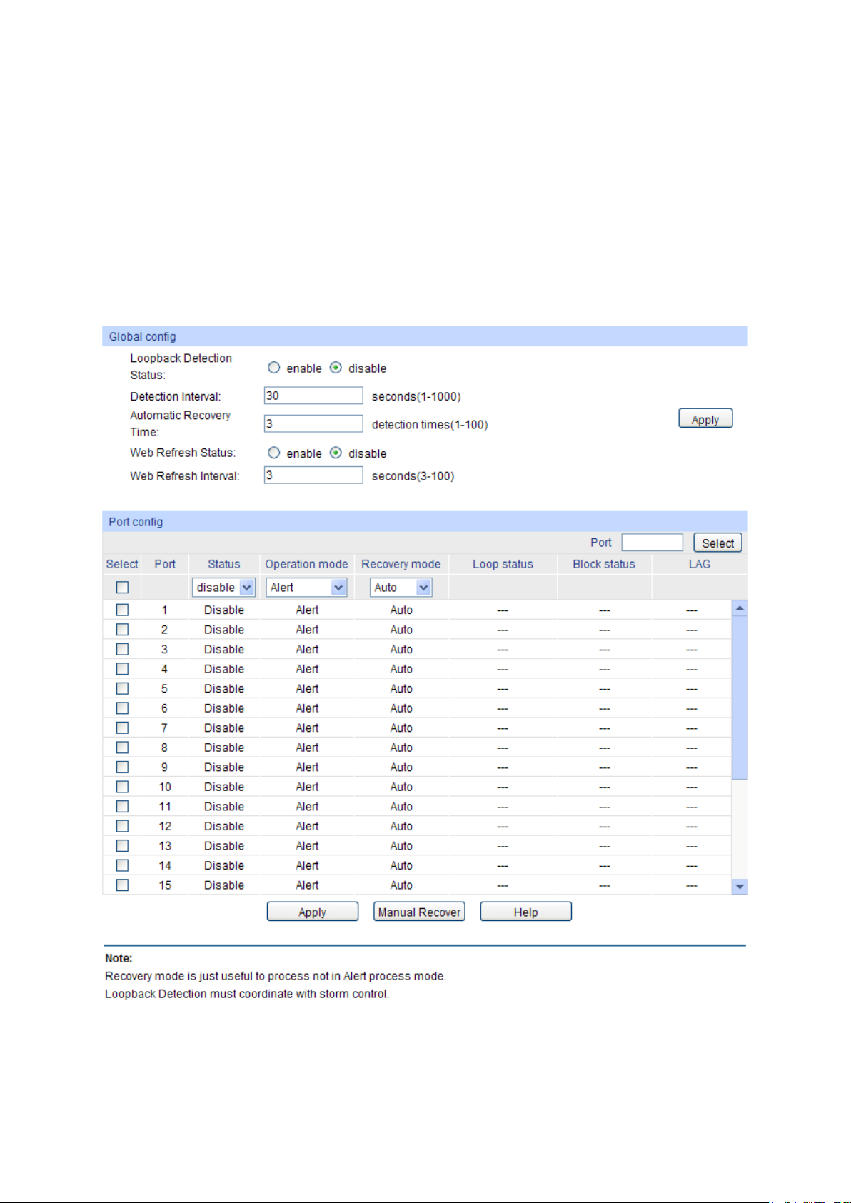
Port Isolation List
Port: Display the port number.
Forward Portlist: Display the Forward Portlist.
5.1.5 Loopback Detection
With loopback detection feature enabled, the switch can detect loops using loopback detection
packets. When a loop is detected, the switch will display an alert or further block the corresponding
port according to the port configuration.
Choose the menu Switching → Port → Loopback Detection to load the following page.
Figure 5-6 Port Isolation Config
50
Page 61

The following entries are displayed on this screen:
function
Automatic Recovery
to
select the corresponding port
Detection configuration. It is
alert and
removed after
Global Config
LoopbackDetection
Status:
Here you can enable or disable Loopback Detection
globally.
Detection Interval: Set a Loopback Detection interval between 1 and 1000 seconds.
By default, it’s 30 seconds.
Time after which the blocked port would automatically recover
Time:
Web Refresh Status:
Web Refresh
Interval:
Port Config
normal status. It can be set as integral times of detection interval.
Here you can enable or disable web automatic refresh.
Set a web refresh interval between 3 and 100 seconds. By default,
it is 3 seconds.
Port Select: Click the Select button to quick-
based on the port number you entered.
Select: Select the desired port for Loopback
multi-optional.
Port Displays the port number.
Status Enable or disable Loopback Detection function for the port.
Operation Mode Select the mode how the switch processes the detected loops.
Alert: When a loop is detected, display an alert.
Port based: When a loop is detected, display an
block the port.
Recovery Mode Select the mode how the blocked port recovers to normal status.
Auto: Block status can be automatically
recovery time.
Manual: Block status only can be removed manuall y.
Loop Status Displays the port status whether a loopback is detected.
Block Status Displays the port status about block or unblock.
LAG Displays the LAG number the port belongs to.
Manual Recover Manually remove the block status of selected ports.
Note:
1. Recovery Mode is not selectable when Alert is chosen in Operation Mode.
2. Loopback Detection must coordinate with storm control.
5.2 LAG
LAG (Link Aggregation Group) is to combine a number of ports together to make a single
high-bandwidth data path, so as to implement the traffic load sharing among the member ports in
the group and to enhance the connection reliability.
51
Page 62
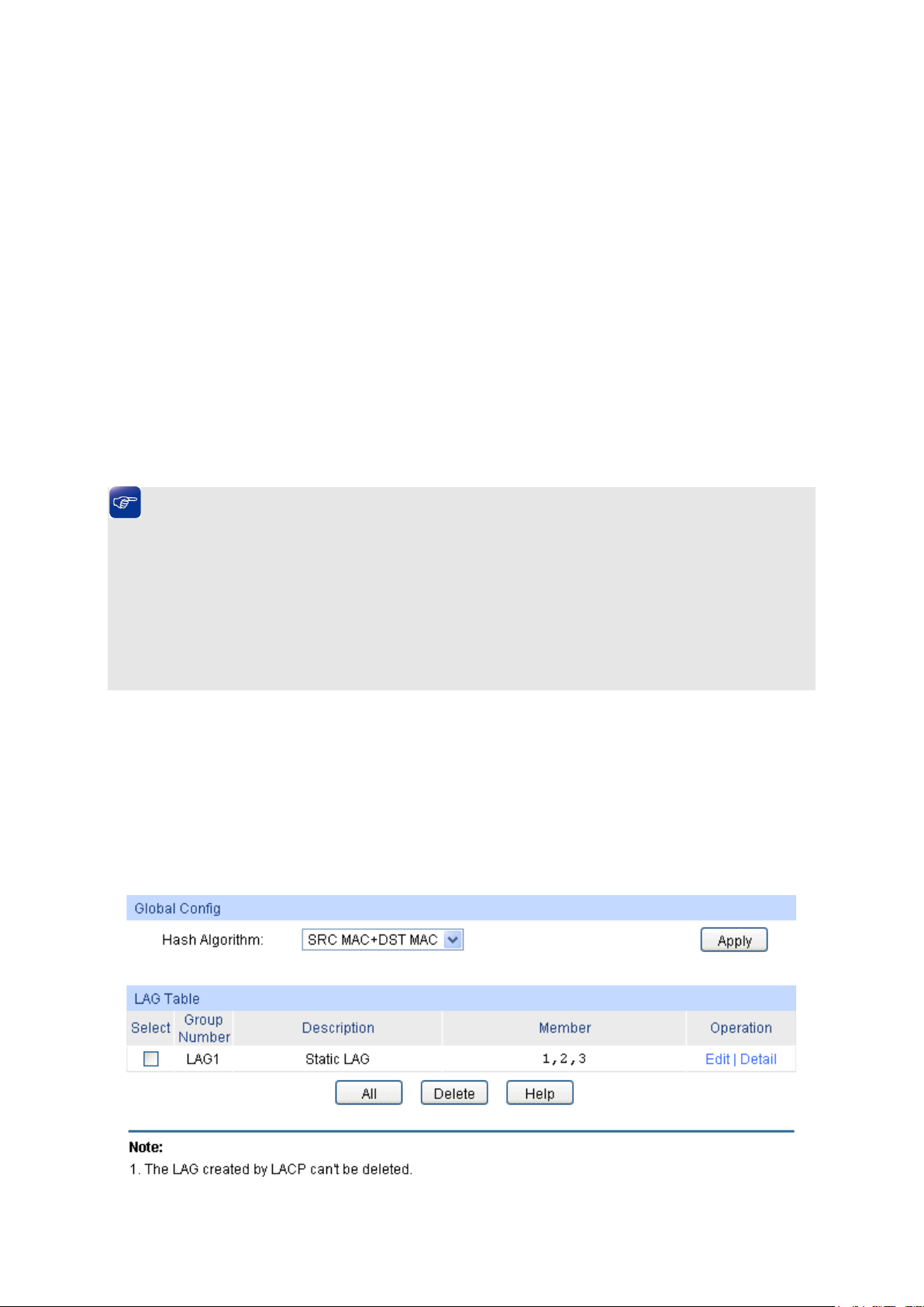
For the member ports in an aggregation group, their basic configuration must be the same. The
basic configuration includes STP, QoS, GVRP, VLAN, port attributes, MAC Address Learning
mode and other associated settings. More details are explained below:
If the ports, which are enabled for the GVRP, 802.1Q VLAN, Voice VLAN, STP, QoS, DHCP
Snooping and Port Configuration (Speed and Flow Control), are in a LAG, their
configurations should be the same.
The ports, which are enabled for the half-duplex, Port Security, Port Mirror, MAC Address
Filtering, Static MAC Address Binding and 802.1X Authentication, cannot be added to the
LA G.
It’s not suggested to add the ports with ARP Inspection and DoS Defend enabled to the
LA G.
If the LAG is needed, you are suggested to configure the LAG function here before configuring the
other functions for the member ports.
Tips:
1. Calculate the bandwidth for a LAG: If a LAG consists of the four ports in the speed of
1000Mbps Full Duplex, the whole bandwidth of the LAG is up to 8000Mbps (2000Mbps * 4)
because the bandwidth of each member port is 2000Mbps counting the up-linked speed of
1000Mbps and the down-linked speed of 1000Mbps.
2. The traffic load of the LAG will be balanced among the ports according to the Aggregate
Arithmetic. If the connections of one or several ports are broken, the traffic of these ports will
be transmitted on the normal ports, so as to guarantee the connection reliability.
Depending on different aggregation modes, aggregation groups fall into two types: Static LAG
and LACP Config. The LAG function is implemented on the LAG Table, Static LAG and LACP
Config configuration pages.
5.2.1 LAG Table
On this page, you can view the information of the current LAG of the switch.
Choose the menu Switching → LAG → LAG Table to load the following page.
Figure 5-6 LAG Table
52
Page 63

The following entries are displayed on this screen:
Hash Algorithm
Select
Group Number
Description
Member
Operation
Global Config
: Select the applied scope of Aggregate Arithmetic, which
results in choosing a port to transfer the packets.
• SRC MAC + DST MAC: When this option is selected,
the Aggregate Arithmetic will apply to the source and
destination MAC addresses of the packets.
• SRC IP + DST IP: When this option is selected, the
Aggregate Arithmetic will apply to the source and
destination IP addresses of the packets.
LAG Table
: Select the desired LAG. It is multi-optional.
: Displays the LAG number here.
: Displays the description of LA G.
: Displays the LAG member.
: Allows you to view or modify the information for each LAG.
• Edit: Click to modify the settings of the LAG.
• Detail: Click to get the information of the LAG.
Click the Detail button for the detailed information of your selected LAG.
Figure 5-7 Detail Information
5.2.2 Static LAG
On this page, you can manually configure the LAG. The LACP feature is disabled for the member
ports of the manually added Static LAG.
53
Page 64
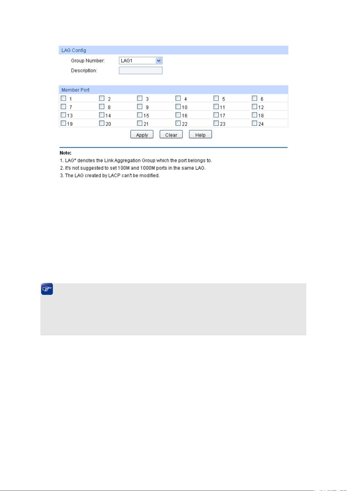
Group Number
Description
Member Port
Select the port as the LAG member. Clearing all the ports of
Choose the menu Switching → LAG → Static LAG to load the following page.
Figure 5-8 Static LAG Config
The following entries are displayed on this screen:
LAG Config
: Select a Group Number for the LAG.
: Give a description to the LAG for identification.
LAG Table
:
the LAG will delete this LAG.
Tips:
1. The LAG can be deleted by clearing its all member ports.
2. A port can only be added to a LAG. If a port is the member of a LAG or is dynamically
aggregated as the LACP member, the port number will be displayed in gray and cannot be
selected.
5.2.3 LACP Config
LACP (Link Aggregation Control Protocol) is defined in IEEE802.3ad and enables the dynamic link
aggregation and disaggregation by exchanging LACP packets with its partner. The switch can
dynamically group similarly configured ports into a single logical link, which will highly extend the
bandwidth and flexibly balance the load.
With the LACP feature enabled, the port will notify its partner of the system priority, system MAC,
port priority, port number and operation key (operation key is determined by the physical
properties of the port, upper layer protocol and admin key). The device with higher priority will lead
the aggregation and disaggregation. System priority and system MAC decide the priority of the
device. The smaller the system priority, the higher the priority of the device is. With the same
system priority, the device owning the smaller system MAC has the higher priority. The device with
the higher priority will choose the ports to be aggregated based on the port priority, port number
and operation key. Only the ports with the same operation key can be selected into an aggregation
54
Page 65
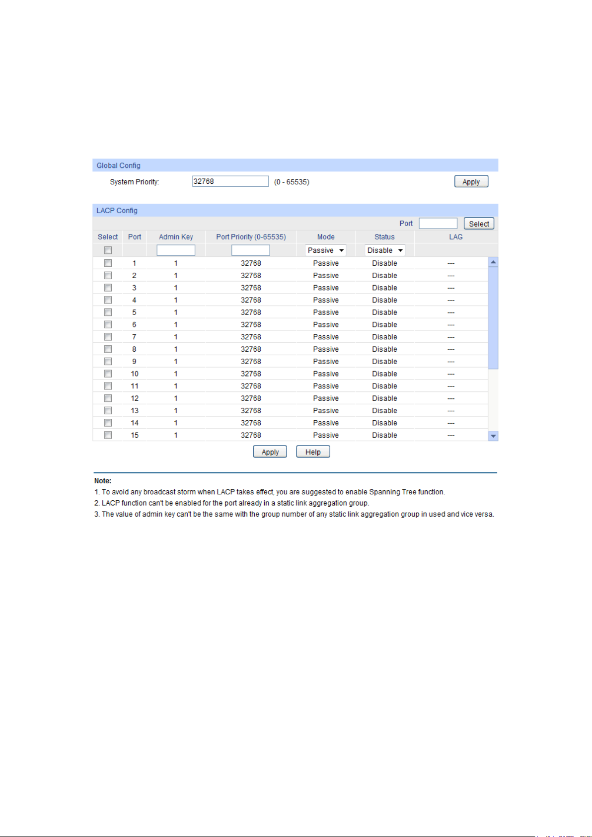
System Priority:
iority and
MAC address constitute the system identification (ID). A lower system
priority value indicates a higher system priority. When exchanging
s to, and the system
Port Select
Select
group. In an aggregation group, the port with smaller port priority will be considered as the
preferred one. If the two port priorities are equal; the port with smaller port number is preferred.
After an aggregation group is established, the selected ports can be aggregated together as one
port to transmit packets.
On this page, you can configure the LACP feature of the switch.
Choose the menu Switching → LAG → LACP Config to load the following page.
Figure 5-9 LACP Config
The following entries are displayed on this screen:
Global Config
Specify the system priority for the switch. The system pr
information between systems, the system with higher priority
determines which link aggregation a link belong
with lower priority adds the proper links to the link aggregation
according to the selection of its partner.
LACP Config
: Click the Select button to quick-select the corresponding port based
: Select the desired port for LACP configuration. It is multi-optional.
on the port number you entered.
55
Page 66

Port
Admin Key
Port Priority
of the port to be selected as the dynamic aggregation group
he port with
Mode:
Status
LAG
: Displays the port number.
: Specify an Admin Key for the port. The member ports in a dynamic
aggregation group must have the same Admin Key.
: Specify a Port Priority for the port. This value determines the priority
member. The port with smaller Port Priority will be considered as the
preferred one. If the two port priorities are equal; t
smaller port number is preferred.
Specify LACP mode for your selected port.
: Enable/Disable the LACP feature for your selected port.
: Displays the LAG number which the port belongs to.
5.3 Traffic Monitor
The Traffic Monitor function, monitoring the traffic of each port, is implemented on the Traffic
Summary and Traffic Statistics pages.
5.3.1 Traffic Summary
Traffic Summary screen displays the traffic information of each port, which facilitates you to
monitor the traffic and analyze the network abnormity.
Choose the menu Switching → Traffic Monitor → Traffic Summary to load the following page.
Figure 5-10 Traffic Summary
56
Page 67

The following entries are displayed on this screen:
Aut
Allows you to Enable/Disable refreshing the Traffic Summary
Refresh Rate
Port Select
d
Port
Packets Rx
Displays the number of packets received on the port. The error
Packets Tx
Octets Rx
isplays the number of octets received on the port. The error octets
Octets Tx
Statistics
button to view the detailed traffic statistics of the
Auto Refresh
o Refresh:
automatically.
: Enter a value in seconds to specify the refresh interval.
Traffic Summary
: Click the Select button to quick-select the corresponding port base
on the port number you entered.
: Displays the port number.
:
packets are not counted in.
: Displays the number of packets transmitted on the port.
: D
are counted in.
: Displays the number of octets transmitted on the port.
: Click the Statistics
port.
5.3.2 Traffic Statistics
Traffic Statistics screen displays the detailed traffic information of each port, which facilitates you to
monitor the traffic and locate faults promptly.
57
Page 68

Auto Refresh
shing the Traffic Summary
Refresh Rate
Port
button to view the traffic
Received
Sent
Broadcast
Mult
Unicast
Choose the menu Switching → Traffic Monitor → Traffic Statistics to load the following page.
Figure 5-11 Traffic Statistics
The following entries are displayed on this screen:
Auto Refresh
: Allows you to Enable/Disable refre
automatically.
: Enter a value in seconds to specify the refresh interval.
Statistics
: Enter a port number and click the Select
statistics of the corresponding port.
: Displays the details of the packets received on the port.
: Displays the details of the packets transmitted on the port.
: Displays the number of good broadcast packets received or
transmitted on the port. The error frames are not counted in.
icast: Displays the number of good multicast packets received or
transmitted on the port. The error frames are not counted in.
: Displays the number of good unicast packets received or
transmitted on the port. The error frames are not counted in.
58
Page 69

Alignment Errors
UndersizePkts
Pkts64Octets
Pkts65to127Octets
Pkts128to255Octets
Pkts256to511Octets
Pkts512to1023Octets
Pkts
Collisions
Relationship between the address
: Displays the number of the received packets that have a bad
Frame Check Sequence (FCS) with a non-integral octet
(Alignment Error). The length of the packet is between 64 bytes
and 1518 bytes.
: Displays the number of the received packets (excluding error
packets) that are less than 64 bytes long.
: Displays the number of the received packets (including error
packets) that are 64 bytes long.
: Displays the number of the received packets (including error
packets) that are between 65 and 127 bytes long.
: Displays the number of the received packets (including error
packets) that are between 128 and 255 bytes long.
: Displays the number of the received packets (including error
packets) that are between 256 and 511 bytes long.
: Displays the number of the received packets (including error
packets) that are between 512 and 1023 bytes long.
Over1023Octets: Displays the number of the received packets (including error
packets) that are over 1023 bytes.
: Displays the number of collisions experienced by a port during
packet transmissions.
5.4 MAC Address
The main function of the switch is forwarding the packets to the correct ports based on the
destination MAC address of the packets. Address Table contains the port-based MAC address
information, which is the base for the switch to forward packets quickly. The entries in the Address
Table can be updated by auto-learning or configured manually. Most entries are generated and
updated by auto-learning. In the stable networks, the static MAC address entries can enhance the
efficiency of packets forwarding remarkably, and the address filtering feature allows the switch to
filter the undesired packets and forbid its forwarding so as to improve the network security.
The types and the features of the MAC Address Table are listed as the following:
Typ e Configuration Way Aging out
Static Manually binding No Being kept The MAC address cannot be learned
after
reboot
and the port
by the other ports in the same VLAN.
Dynamic Auto-learning Yes Clear The MAC address can be learned by
Filtering Manually binding No Being kept -
This function includes four submenus: Address Table, Static Address, Dynamic Address and
Filtering Address.
the other ports in the same VLAN.
Table 5-1 Types and features of Address Table
59
Page 70
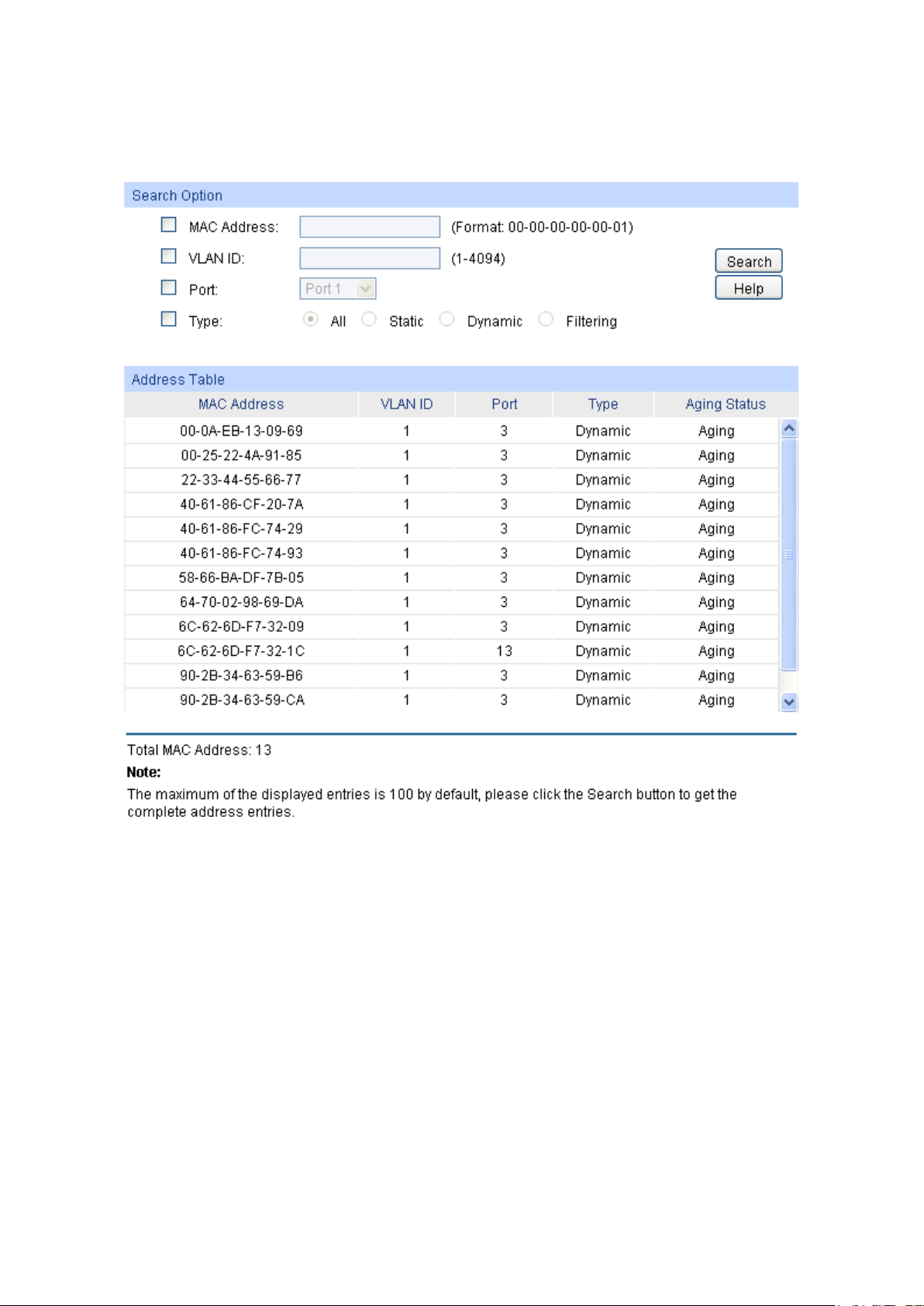
MAC Address
VLAN ID
Port
Typ e
the
This option allows the address table to display the static
This option allows the address table to display the
play the
5.4.1 Address Table
On this page, you can view all the information of the Address Table.
Choose the menu Switching → MAC Address → Address Table to load the following page.
Figure 5-12 Address Table
The following entries are displayed on this screen:
Search Option
: Enter the MAC address of your desired entry.
: Enter the VLAN ID of your desired entry.
: Select the corresponding port number of your desired entry.
: Select the type of your desired entry.
All: This option allows the address table to display all
address entries.
Static:
address entries only.
Dynamic:
dynamic address entries only.
Filtering: This option allows the address table to dis
filtering address entries only.
60
Page 71
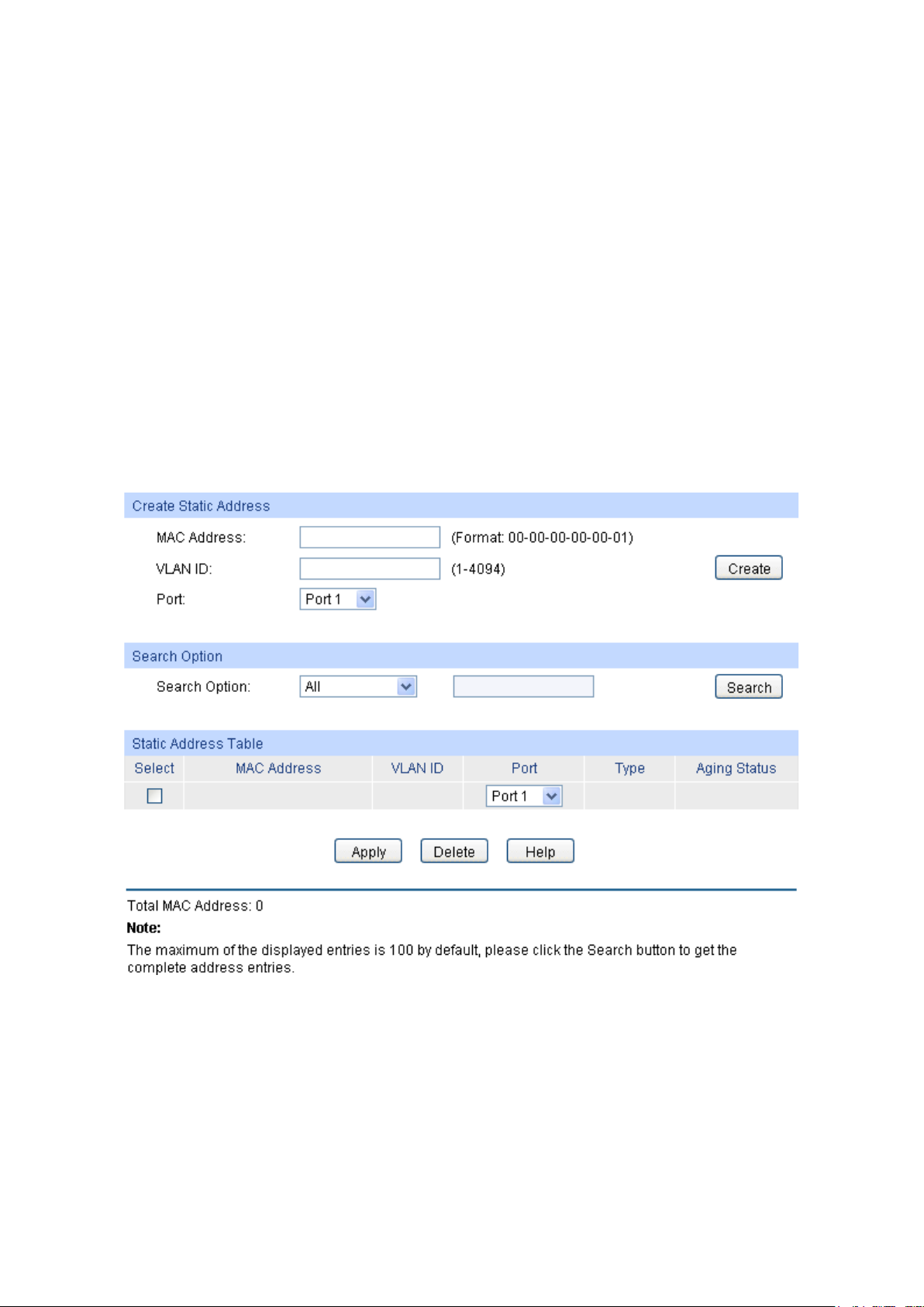
MAC Address
VLAN ID
Port
Typ e
Aging Status
MAC Address
VLAN ID
Port
Address Table
: Displays the MAC address learned by the switch.
: Displays the corresponding VLAN ID of the MAC address.
: Displays the corresponding Port number of the MAC address.
: Displays the Type of the MAC address.
: Displays the Aging status of the MAC address.
5.4.2 Static Address
The static address table maintains the static address entries which can be added or removed
manually, independent of the aging time. In the stable networks, the static MAC address entries
can facilitate the switch to reduce broadcast packets and remarkably enhance the efficiency of
packets forwarding without learning the address. The static MAC address learned by the port with
Port Security enabled in the static learning mode will be displayed in the Static Address Table.
Choose the menu Switching → MAC Address → Static Address to load the following page.
Figure 5-13 Static Address
The following entries are displayed on this screen:
Create Static Address
: Enter the static MAC Address to be bound.
: Enter the corresponding VLAN ID of the MAC address.
: Select a port from the pull-down list to be bound.
61
Page 72

Search Option
Search
Select
the corresponding port number. It
MAC Address
VLAN ID
Port: Displays the corresponding Port number of the MAC address. Here
ort number to which the MAC address is bound.
Typ e
Aging Status
Search Option
: Select a Search Option from the pull-down list and click the
Static Address Table
: Select the entry to delete or modify
: Displays the static MAC Address.
: Displays the corresponding VLAN ID of the MAC address.
: Displays the Type of the MAC address.
button to find your desired entry in the Static Address Table.
• MAC: Enter the MAC address of your desired entry.
• VLAN ID: Enter the VLAN ID number of your desired entry.
• Port: Enter the Port number of your desired entry.
is multi-optional.
you can modify the p
The new port should be in the same VLAN.
: Displays the Aging Status of the MAC address.
Note:
1. If the corresponding port number of the MAC address is not correct, or the connected port (or
the device) has been changed, the switch cannot forward the packets correctly. Please reset
the static address entry appropriately.
2. If the MAC address of a device has been added to the Static Address Table, connecting the
device to another port will cause its address not to be recognized dynamically by the switch.
Therefore, please ensure the entries in the Static Address Table are correct and valid.
3. The MAC address in the Static Address Table cannot be added to the Filtering Address Table
or bound to a port dynamically.
5.4.3 Dynamic Address
The dynamic address can be generated by the auto-learning mechanism of the switch. The
Dynamic Address Table can update automatically by auto-learning or the MAC address aging out
mechanism.
To fully utilize the MAC address table, which has a limited capacity, the switch adopts an aging
mechanism for updating the table. That is, the switch removes the MAC address entries related to
a network device if no packet is received from the device within the aging time.
On this page, you can configure the dynamic MAC address entry.
62
Page 73
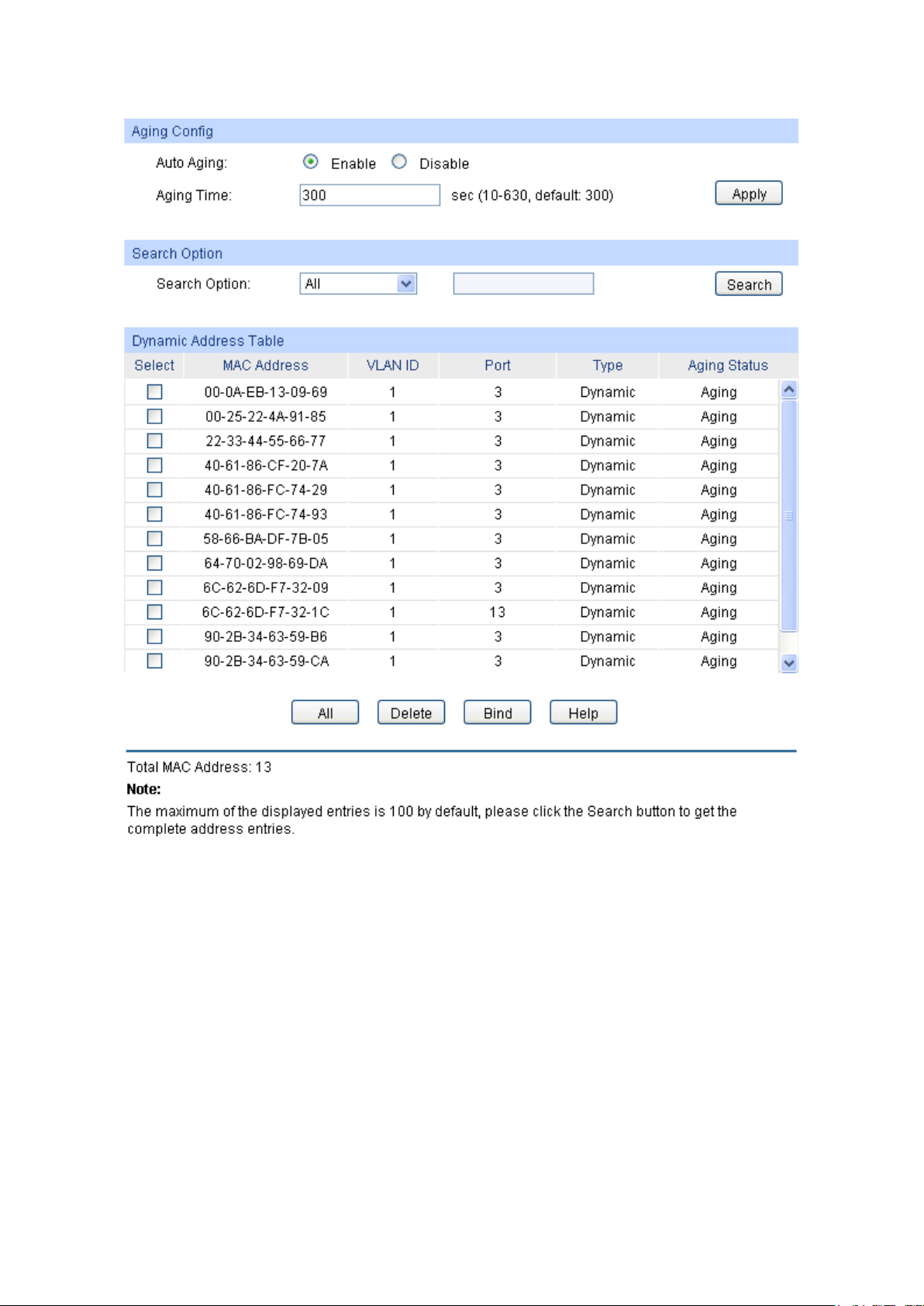
Auto Aging
Aging Time
Search Option
Search
Choose the menu Switching → MAC Address → Dynamic Address to load the following page.
Figure 5-14 Dynamic Address
The following entries are displayed on this screen:
Aging Config
: Allows you to Enable/Disable the Auto Aging feature.
: Enter the Aging Time for the dynamic address.
Search Option
: Select a Search Option from the pull-down list and click the
button to find your desired entry in the Dynamic Address Table.
• MAC: Enter the MAC address of your desired entry.
• VLAN ID: Enter the VLAN ID number of your desired entry.
• Port: Enter the Port number of your desired entry.
• LAG ID: Enter the LAG ID number of your desired entry.
63
Page 74
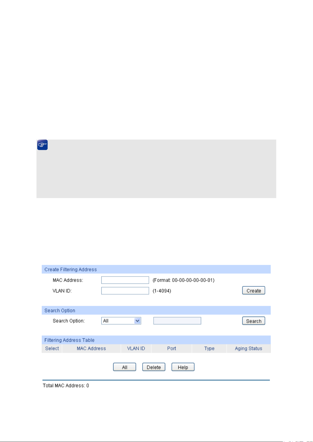
Select: Select the entry to delete the dynamic address or to bind the MAC
MAC Address
VLAN ID
Port
Typ e
Aging Status
Bind
button to bind the MAC address of your selected entry to
Dynamic Address Table
address to the corresponding port statically. It is multi-optional.
: Displays the dynamic MAC Address.
: Displays the corresponding VLAN ID of the MAC address.
: Displays the corresponding port number of the MAC address.
: Displays the Type of the MAC address.
: Displays the Aging Status of the MAC address.
: Click the Bind
the corresponding port statically.
Tips:
Setting aging time properly helps implement effective MAC address aging. The aging time that is
too long or too short results in a decrease the performance of the switch. If the aging time is too
long, excessive invalid MAC address entries maintained by the switch may fill up the MAC address
table. This prevents the MAC address table from updating with network changes in time. If the
aging time is too short, the switch may remove valid MAC address entries. This decreases the
forwarding performance of the switch. It is recommended to keep the default value.
5.4.4 Filtering Address
The filtering address is to forbid the undesired packets to be forwarded. The filtering address can
be added or removed manually, independent of the aging time. The filtering MAC address allows
the switch to filter the packets which includes this MAC address as the source address or
destination address, so as to guarantee the network security. The filtering MAC address entries
act on all the ports in the corresponding VLAN.
Choose the menu Switching → MAC Address → Filtering Address to load the following page.
Figure 5-15 Filtering Address
64
Page 75

The following entries are displayed on this screen:
MAC Address
VLAN ID
Search Option
Select
ry to delete the corresponding filtering address. It is
MAC Address
VLAN ID
Port
Typ e
Aging Status
Create Filtering Address
: Enter the MAC Address to be filtered.
: Enter the corresponding VLAN ID of the MAC address.
Search Option
: Select a Search Option from the pull-down list and click the Search
button to find your desired entry in the Filtering Address Table.
• MAC: Enter the MAC address of your desired entry.
• VLAN ID: Enter the VLAN ID number of your desired entry.
Filtering Address Table
: Select the ent
multi-optional.
: Displays the filtering MAC Address.
: Displays the corresponding VLAN ID.
: Here the symbol “__” indicates no specified port.
: Displays the Type of the MAC address.
: Displays the Aging Status of the MAC address.
Note:
1. The MAC address in the Filtering Address Table cannot be added to the Static Address Table
or bound to a port dynamically.
2. This MAC address filtering function is not available if the 802.1X feature is enabled.
Return to CONTENTS
65
Page 76
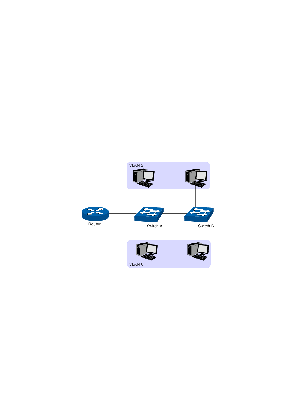
Chapter 6 VLAN
The traditional Ethernet is a data network communication technology based on CSMA/CD (Carrier
Sense Multiple Access/Collision Detect) via shared communication medium. Through the
traditional Ethernet, the overfull hosts in LAN will result in serious collision, flooding broadcasts,
poor performance or even breakdown of the Internet. Though connecting the LANs through
switches can avoid the serious collision, the flooding broadcasts cannot be prevented, which will
occupy plenty of bandwidth resources, causing potential serious security problems.
A Virtual Local Area Network (VLAN) is a network topology configured according to a logical
scheme rather than the physical layout. The VLAN technology is developed for switches to control
broadcast in LANs. By creating VLANs in a physical LAN, you can divide the LAN into multiple
logical LANs, each of which has a broadcast domain of its own. Hosts in the same VLAN
communicate with one another as if they are in a LAN. However, hosts in different VLANs cannot
communicate with one another directly. Therefore, broadcast packets are limited in a VLAN. Hosts
in the same VLAN communicate with one another via Ethernet whereas hosts in different VLANs
communicate with one another through the Internet devices such as router, the Layer 3 switch, etc.
The following figure illustrates a VLAN implementation.
Figure 6-1 VLAN implementation
Compared with the traditional Ethernet, VLAN enjoys the following advantages.
(1) Broadcasts are confined to VLANs. This decreases bandwidth utilization and improves
network performance.
(2) Network security is improved. VLANs cannot communicate with one another directly. That
is, a host in a VLAN cannot access resources in another VLAN directly, unless routers or
Layer 3 switches are used.
(3) Network configuration workload for the host is reduced. VLAN can be used to group
specific hosts. When the physical position of a host changes within the range of the VLAN,
you need not to change its network configuration.
A VLAN can span across multiple switches, or even routers. This enables hosts in a VLAN to be
dispersed in a looser way. That is, hosts in a VLAN can belong to different physical network
segments. This switch supports three ways, namely, 802.1Q VLAN, MAC VLAN and Protocol
VLAN, to classify VLANs. VLAN tags in the packets are necessary for the switch to identify
66
Page 77

packets of different VLANs. The switch can analyze the received untagged packets on the port and
match the packets with the MAC VLAN, Protocol VLAN and 802.1Q VLAN in turn. If a packet is
matched, the switch will add a corresponding VLAN tag to it and forward it in the corresponding
VLAN.
6.1 802.1Q VLAN
VLAN tags in the packets are necessary for the switch to identify packets of different VLANs. The
switch works at the data link layer in OSI model and it can identify the data link layer encapsulation
of the packet only, so you can add the VLAN tag field into the data link layer encapsulation for
identification.
In 1999, IEEE issues the IEEE 802.1Q protocol to standardize VLAN implementation, defining the
structure of VLAN-tagged packets. IEEE 802.1Q protocol defines that a 4-byte VLAN tag is
encapsulated after the destination MAC address and source MAC address to show the information
about VLAN.
As shown in the following figure, a VLAN tag contains four fields, including TPID (Tag Protocol
Identifier), Priority, CFI (Canonical Format Indicator), and VLAN ID.
Figure 6-2 Format of VLAN Tag
(1) TPID: TPID is a 16-bit field, indicating that this data frame is VLAN-tagged. By default, it is
0x8100 in this switch.
(2) Priority: Priority is a 3-bit field, referring to 802.1p priority. Refer to section “QoS & QoS
profile” for details.
(3) CFI: CFI is a 1-bit field, indicating whether the MAC address is encapsulated in the
standard format in different transmission media. This field is not described in detail in this
chapter.
(4) VLAN ID: VLAN ID is a 12-bit field, indicating the ID of the VLAN to which this packet
belongs. It is in the range of 0 to 4,095. Generally, 0 and 4,095 is not used, so the field is in
the range of 1 to 4,094.
VLAN ID identifies the VLAN to which a packet belongs. When the switch receives an untagged
packet, it will encapsulate a VLAN tag with the default VLAN ID of the inbound port for the packet,
and the packet will be assigned to the default VLAN of the inbound port for transmission.
In this User Guide, the tagged packet refers to the packet with VLAN tag whereas the untagged
packet refers to the packet without VLAN tag, and the priority-tagged packet refers to the packet
with VLAN tag whose VLAN ID is 0.
Link Types of ports
When creating the 802.1Q VLAN, you should set the link type for the port according to its
connected device. The link types of port including the following three types:
(1) ACCESS: The ACCESS port can be added in a single VLAN, and the egress rule of the
port is UNTAG. The PVID is same as the current VLAN ID. If the ACCESS port is added to
another VLAN, it will be removed from the current VLAN automatically.
67
Page 78

When untagged
packets are
received, the port
will add the default
VLAN tag, i.e. the
PVID of the ingress
not the same as the
PVID of the port, the
The packet will be
forbidden by the port,
he packet will be
The packet will be
forwarded with its current
If the egress rule of port is
TAG, the packet will be
forwarded with its current
If the egress rule of port is
UNTAG, the packet will be
(2) TRUNK: The TRUNK port can be added in multiple VLANs, and the egress rule of the port
is TAG. The TRUNK port is generally used to connect the
cascaded network devices for it
can receive and forward the packets of multiple VLANs. When the packets are forwarded
by the TRUNK port, its VLAN tag will not be changed.
(3) GENERAL: The GENERAL port can be added in multiple VLANs and set various egress
rules according to the different VLANs. The default egress rule is UNTAG. The PVID can
be set as the VID number of any VLAN the port belongs to.
PVID
PVID (Port VLAN ID) is the default VID of the port. When the switch receives an untagged packet,
it will add a VLAN tag to the packet according to the PVID of its received port and forward the
packets.
When creating VLANs, the PVID of each port, indicating the default VLAN to which the port
belongs, is an important parameter with the following two purposes:
(1) When the switch receives an untagged packet, it will add a VLAN tag to the packet
according to the PVID of its received port
(2) PVID determines the default broadcast domain of the port, i.e. when the port receives UL
packets or broadcast packets, the port will broadcast the packets in its default VLAN.
Different packets, tagged or untagged, will be processed in different ways, after being received by
ports of different link types, which is illustrated in the following table.
Port Type
Access
Trunk
General
Table 6-1 Relationship between Port Types and VLAN Packets Processing
Receiving Packets
Untagged Packets Tagged Packets
If the VID of packet is
the same as the PVID
of the port, the packet
will be received.
If the VID of packet is
packet will be dropped.
If the VID of packet is
port, to the packets.
allowed by the port, the
packet will be received.
If the VID of packet is
t
dropped.
68
Forwarding Packets
forwarded after removing its
VLAN tag.
VLAN tag.
VLAN tag.
forwarded after removing its
VLAN tag.
Page 79

select the corresponding entry
Select the desired entry to delete the corresponding VLAN. It is
:
IEEE 802.1Q VLAN function is implemented on the VLAN Config and Port Config pages.
6.1.1 VLAN Config
On this page, you can view the current created 802.1Q VLAN.
Choose the menu VLAN → 802.1Q VLAN → VLAN Config to load the following page.
Figure 6-3 VLAN Table
To ensure the normal communication of the factory switch, the default VLAN of all ports is set to
VLAN1. VLAN1 cannot be modified or deleted.
The following entries are displayed on this screen:
VLAN Table
VLAN ID Select:
Select:
VLAN ID:
Description:
Members:
Operation
Click the Select button to quickbased on the VLAN ID number you entered.
multi-optional.
Displays the ID number of VLAN.
Displays the user-defined description of VLAN.
Displays the port members in the VLAN.
Allows you to view or modify the information for each entry.
• Edit: Click to modify the settings of VLAN.
• Detail: Click to get the information of VLAN.
69
Page 80

check whether the VLAN ID you entered
select the corresponding entry
k.
Click Edit button to modify the settings of the corresponding VLAN. Click Create button to create a
new VLAN.
Figure 6-4 Create or Modify 802.1Q VLAN
The following entries are displayed on this screen:
VLAN Config
VLAN ID: Enter the ID number of VLAN.
Description: Give a description to the VLAN for identification.
Check:
Click the Check button to
is valid or not.
VLAN Members
Port Select: Click the Select button to quick-
based on the port number you entered.
Select: Select the desired port to be a member of VLAN or leave it blan
It's multi-optional.
Port: Displays the port number.
70
Page 81

Displays the Link Type of the port. It can be reset on Port Config
Select the Egress Rule for the VLAN port member. The default
ts forwarded by the port are tagged. The
ect the corresponding entry
Link Type:
screen.
Egress Rule:
egress rule is UNTAG.
• TAG: All packe
packets contain VLAN information.
• UNTAG: Packets forwarded by the port are untagged.
LAG: Displays the LAG to which the port belongs.
6.1.2 Port Config
Before creating the 802.1Q VLAN, please acquaint yourself with all the devices connected to the
switch in order to configure the ports properly.
Choose the menu VLAN→ 802.1Q VLAN → Port Config to load the following page.
Figure 6-5 802.1Q VLAN – Port Config
The following entries are displayed on this screen:
VLAN Port Config
Port Select: Click the Select button to quick-sel
based on the port number you entered.
Select:
Port:
Select the desired port for configuration. It is multi-optional.
Displays the port number.
71
Page 82

e ACCESS port can be added in a single VLAN,
and the egress rule of the port is UNTAG. The PVID is same
as the current VLAN ID. If the current VLAN is deleted, the
TRUNK: The TRUNK port can be added in multiple VLANs,
the egress rule of the port is TAG. The PVID can be set as
GENERAL: The GENERAL port can be added in multiple
VLANs and set various egress rules according to the different
TAG. The PVID can be
button to view the information of the VLAN to
VLAN ID Select:
Click the Select button to quick-select the corresponding entry
VLAN Name:
Operation:
Allows you to remove the port from the current VLAN.
Set the link type for
the description for the VLAN. Meanwhile, specify its member
Link Type:
Select the Link Type from the pull-down list for the port.
• ACCESS: Th
PVID will be set to 1 by default.
•
and
the VID number of any VLAN the port belongs to.
•
VLANs. The default egress rule is UN
set as the VID number of any VLAN the port belongs to.
PVID: Enter the PVID number of the port.
LAG: Displays the LAG to which the port belongs.
VLAN:
Click the Detail
which the port belongs.
Click the Detail button to view the information of the corresponding VLAN
Figure 6-6 View the Current VLAN of Port
The following entries are displayed on this screen:
VLAN of Port
based on the VLAN ID number you entered.
VLAN ID:
Displays the ID number of VLAN.
Displays the user-defined description of VLAN.
Configuration Procedure:
Step Operation Description
1
port.
2 Create VLAN. Required. On the VLAN→802.1Q VLAN→VLAN Config page,
Required. On the VLAN→802.1Q VLAN→Port Config page, set
the link type for the port based on its connected device.
click the Create button to create a VLAN. Enter the VLAN ID and
ports.
72
Page 83

Step Operation Description
3 Modify/View VLAN. Optional. On the VLAN→802.1Q VLAN→VLAN Config page,
click the Edit/Detail button to modify/view the information of the
corresponding VLAN.
4 Delete VLAN Optional. On the VLAN→802.1Q VLAN→VLAN Config page,
select the desired entry to delete the corresponding VLAN by
clicking the Delete button.
6.2 MAC VLAN
MAC VLAN technology is the way to classify VLANs according to the MAC addresses of Hosts. A
MAC address corresponds to a single VLAN ID. For the device in a MAC VLAN, if its MAC address
is bound to VLAN, the device can be connected to another member port in this VLAN and still
takes its member role effect without changing the configuration of VLAN members.
The packet in MAC VLAN is processed in the following way:
1. When receiving an untagged packet, the switch matches the packet with the current MAC
VLAN. If the packet is matched, the switch will add a corresponding MAC VLAN tag to it. If no
MAC VLAN is matched, the switch will add a tag to the packet according to the PVID of the
received port. Thus, the packet is assigned automatically to the corresponding VLAN for
transmission.
2. When receiving tagged packet, the switch will process it based on the 802.1Q VLAN. If the
received port is the member of the VLAN to which the tagged packet belongs, the packet will
be forwarded normally. Otherwise, the packet will be discarded.
3. If the MAC address of a Host is classified into 802.1Q VLAN, please set its connected port of
switch to be a member of this 802.1Q VLAN so as to ensure the packets forwarded normally.
On this page, you can create MAC VLAN and view the current MAC VLANs in the table.
Choose the menu VLAN → MAC VLAN to load the following page.
Figure 6-7 Create and View MAC VLAN
73
Page 84

The following entries are displayed on this screen:
Description:
VLAN ID:
Enter the ID number of the MAC VLAN. This VLAN should be one of the
select the corresponding entry based
button to modify the settings of the entry. And click the
Set the link type for
page, create the MAC
VLAN Table
MAC Address:
Enter the MAC address.
Give a description to the MAC address for identification.
802.1Q VLANs the ingress port belongs to.
MAC VLAN Table
MAC Select: Click the Select button to quick-
on the MAC address you entered.
Select: Select the desired entry. It is multi-optional.
MAC Address: Displays the MAC address.
Description: Displays the user-defined description of the MAC address.
VLAN ID: Displays the corresponding VLAN ID of the MAC address.
Operation: Click the Edit
Modify button to apply your settings.
Configuration Procedure:
Step Operation Description
1
port
Required. On the VLAN→802.1Q VLAN→Port Config page, set
the link type for the port based on its connected device.
2 Create VLAN Required. On the VLAN→802.1Q VLAN→VLAN Config page,
click the Create button to create a VLAN. Enter the VLAN ID and
the description for the VLAN. Meanwhile, specify its member
ports.
3 Create MAC VLAN Required. On the VLAN→MAC VLAN
VLAN. For the device in a MAC VLAN, it’s required to set its
connected port of switch to be a member of this VLAN so as to
ensure the normal communication.
6.3 Protocol VLAN
Protocol VLAN is another way to classify VLANs based on network protocol. Protocol VLANs can
be sorted by IP, IPX, DECnet, AppleTalk, Banyan and so on. Through the Protocol VLANs, the
broadcast domain can span over multiple switches and the Host can change its physical position
in the network with its VLAN member role always effective. By creating Protocol VLANs, the
network administrator can manage the network clients based on their actual applications and
services effectively.
Protocol VLAN, another way to classify VLANs based on network protocol, can bind ToS provided
in the network to VLAN to realize the specific service. Through protocol VLAN, the switch can
analyze the received untagged packets on the port and match the packets with the user-defined
protocol template according to different encapsulation formats and the values of the special fields.
If a packet is matched, the switch will add a corresponding VLAN tag to it automatically and thus
74
Page 85

the data of specific protocol can be automatically assigned to the corresponding VLAN for
transmission. The network administrator can manage network clients based on their specific
applications and services through protocol VLAN.
Encapsulation Format of Ethernet Data
This section simply introduces the common used encapsulation format of Ethernet data to
understand the procedure for the switch to identify the protocol of packets. At present there are
two encapsulation formats of Ethernet data, Ethernet II encapsulation and 802.2/802.3
encapsulation, shown as follows:
Ethernet II encapsulation
802.2/802.3 encapsulation
DA and SA respectively refer to destination MAC address and source MAC address. The
number indicates the length of the field in bytes, for example, the length of source MAC
address is 12 bytes.
As the maximum length of Ethernet data is 1500 bytes, that is, 0x05DC in hexadecimal, the
Length field in 802.2/802.3 encapsulation ranges from 0x0000 to 0x05DC, but the Type field
in Ethernet II encapsulation ranges from 0x0600 to 0xFFF. The Type or Length field in the
range of 0x05DD to 0x05FF is recognized as illegal and will be directly discarded. The switch
identifies whether a packet is Ethernet II packet or 802.2/802.3 packet according to the
ranges of the two fields.
802.2/802.3 encapsulation contains the following three extended formats:
802.3 raw encapsulation
Only the Length field is encapsulated after source MAC address field and destination MAC
address field, followed by DATA field without other fields. Currently only IPX protocol supports
802.3 raw encapsulation format. The last two bytes of the Length field in 802.3 raw
encapsulation is 0xFFFF.
802.2LLC (Logic Link Control) encapsulation
The Length field, DSAP (Destination Service Access Point) field, SSAP (Source Service
Access Point) field and Control field are encapsulated after source MAC address field and
destination MAC address field. The value of Control field is always 3. DSAP field and SSAP
field in 802.2 LLC encapsulation are used to identify the upper layer protocol, for example,
when both the two fields are 0xE0, it indicates the upper layer protocol is IPX.
802.2 SNAP (Sub-Network Access Protocol) is encapsulated based on 802.3 standard
packets. In 802.2 SNAP encapsulation, the values of both DSAP field and SSAP field are
always 0XAA, and the value of Control field is 3. The switch differentiates 802.2 LLC and
802.2 SNAP encapsulation formats according to the values of DSAP field and SSAP field.
The device determines the encapsulation format of its sending packets, and a device can send out
packets of two encapsulation formats. Ethernet II encapsulation format is the most common used
one currently.
802.3 and Ethernet II encapsulation formats are supported in IP protocol, ARP protocol and RARP
protocol, but not supported in all protocols. The switch identifies the protocol of the packets by
matching eigenvalues of two encapsulation formats.
75
Page 86
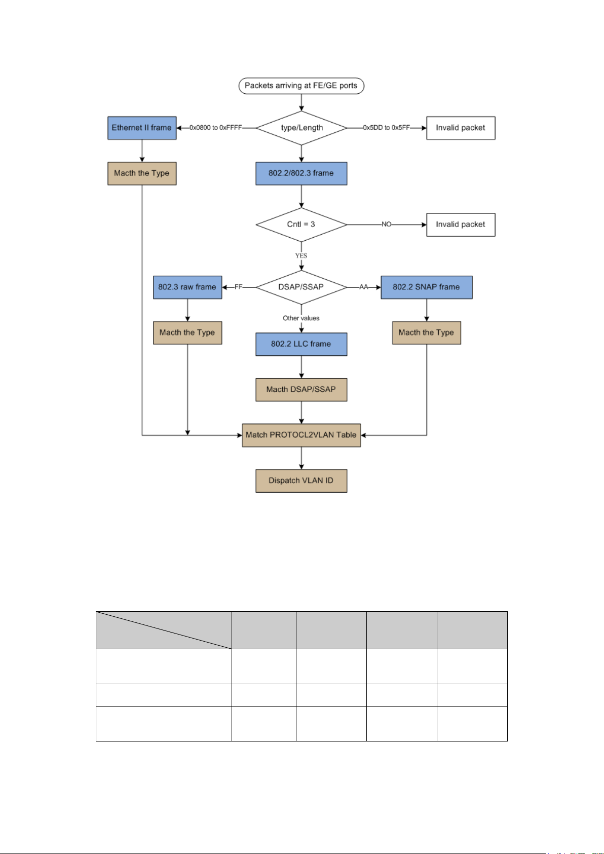
The Procedure for the Switch to Identify Packet Protocol
The Implementation of Protocol VLAN
This switch can match packets through protocol template and transmit packets in the specific
VLAN according to the protocol. Protocol template, comprising encapsulation format and protocol
type, is the standard to determine the protocol which a packet belongs to. The following table
shows the common used encapsulation formats supported in network layer protocol and the
protocol templates are for reference. Meanwhile some protocol templates has been preset in the
switch, you can create protocol VLAN according to the corresponding protocol template.
Encapsulation
Ethernet II
802.3 raw 802.2 LLC 802.2 SNAP
Protocol
IP(0x0800)
IPX(0x8137)
AppleTalk(0x809B)
Supported
Not
supported
Supported Supported Supported Supported
Supported
Not
supported
Not
supported
Not
supported
Supported
Supported
Table 6-2 Protocol types in common use
76
Page 87
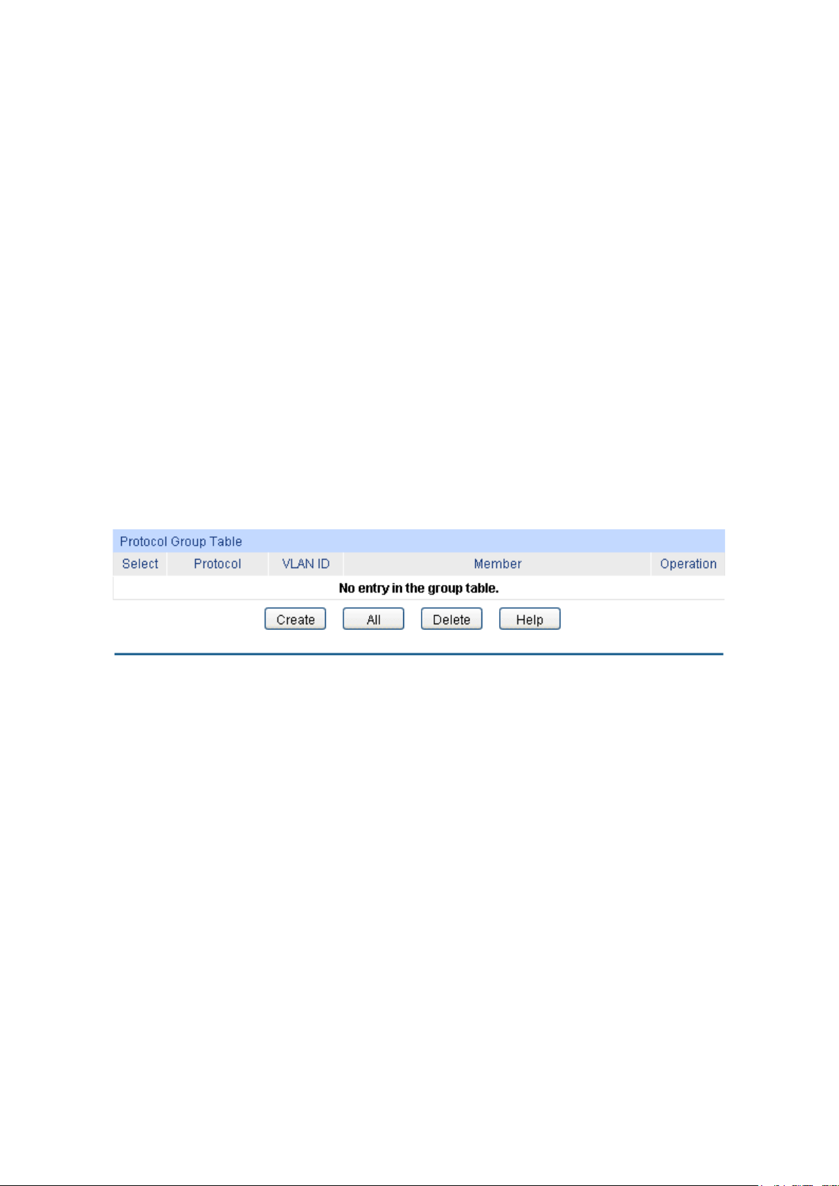
Select
Protocol
VLAN ID:
Member:
Operation:
entry. And click the
The packet in Protocol VLAN is processed in the following way:
VLAN packets are processed in the following way:
1. When receiving an untagged packet, the switch matches the packet with the current Protocol
VLAN. If the packet is matched, the switch will add a corresponding Protocol VLAN tag to it. If
no Protocol VLAN is matched, the switch will add a tag to the packet according to the PVID of
the received port. Thus, the packet is assigned automatically to the corresponding VLAN for
transmission.
2. When receiving tagged packet, the switch will process it based on the 802.1Q VLAN. If the
received port is the member of the VLAN to which the tagged packet belongs, the packet will
be forwarded normally. Otherwise, the packet will be discarded.
3. If the Protocol VLAN is created, please set its enabled port to be the member of
corresponding 802.1Q VLAN so as to ensure the packets forwarded normally.
6.3.1 Protocol Group Table
On this page, you can create Protocol VLAN and view the information of the current defined
Protocol VLANs.
Choose the menu VLAN → Protocol VLAN → Protocol Group Table to load the following page.
Figure 6-8 Protocol Group Table
The following entries are displayed on this screen:
Protocol Group Table
: Select the desired entry. It is multi-optional.
: Displays the protocol of the protocol group.
Displays the corresponding VLAN ID of the protocol group.
Displays the member of the protocol group.
Click the Edit button to modify the settings of the
Modify button to apply your settings.
6.3.2 Protocol Group
On this page, you can create Protocol VLAN and view the information of the current defined
Protocol VLANs.
Choose the menu VLAN → Protocol VLAN → Protocol Group to load the following page.
77
Page 88
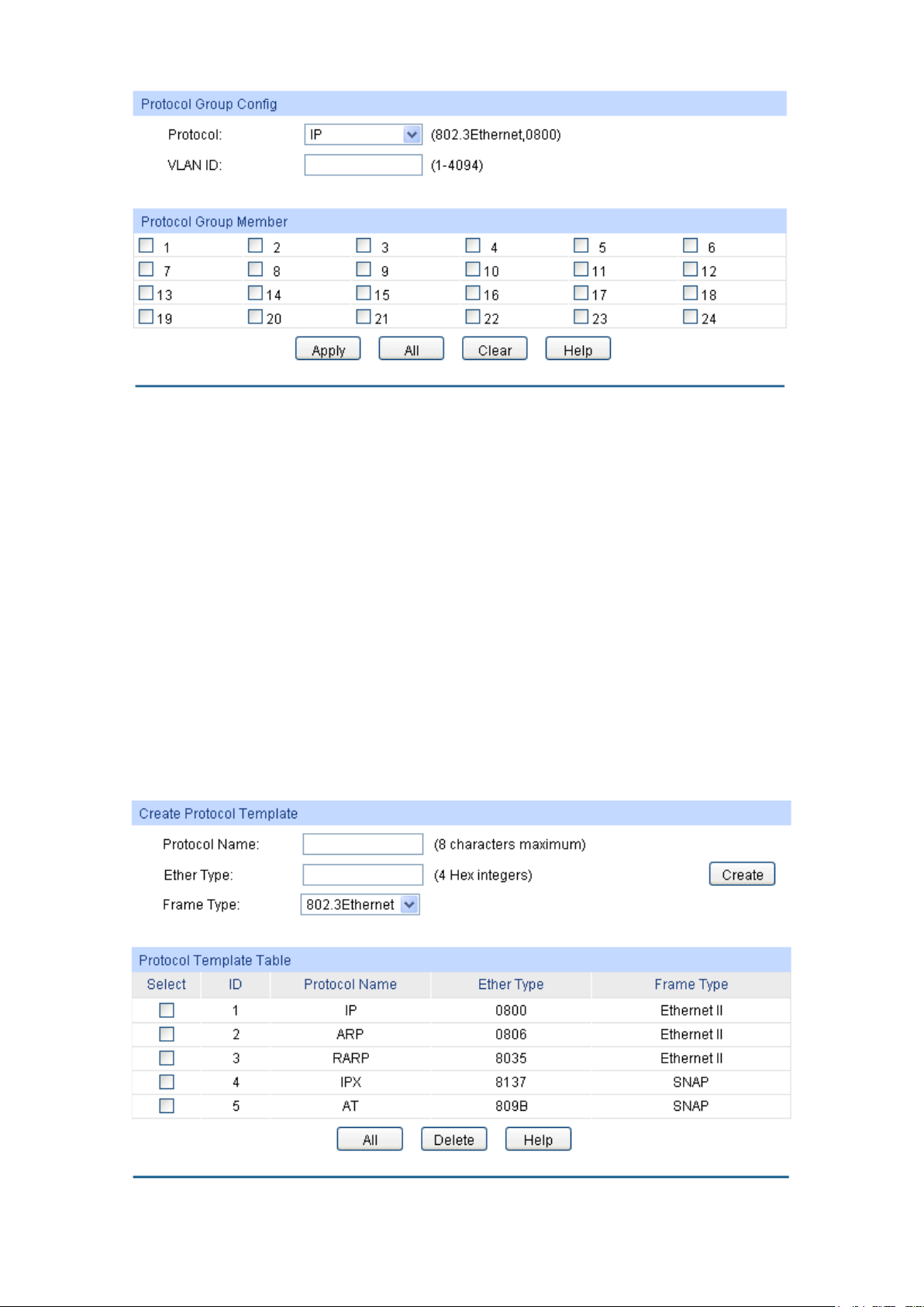
Protocol:
VLAN ID:
Enter the ID number of the Protocol VLAN. This VLAN should be one
Figure 6-9 Create Protocol VLAN
The following entries are displayed on this screen:
Protocol Group Config
Select the defined protocol template.
of the 802.1Q VLANs the ingress port belongs to.
Protocol Group Member
Select your desired port for Protocol VLAN Group.
6.3.3 Protocol Template
The Protocol Template should be created before configuring the Protocol VLAN. By default, the
switch has defined the IP Template, ARP Template, RARP Template, etc. You can add more
Protocol Template on this page.
Choose the menu VLAN → Protocol VLAN → Protocol Template to load the following page.
Figure 6-10 Create and View Protocol Template
78
Page 89
Protocol Name:
Ether Type:
Frame Type:
Select:
ID
Protocol Name:
Ether Type:
Frame Type
VLAN ID and the description for the VLAN. Meanwhile,
page, create the Protocol Template before
button to modify/view the
y to delete the
The following entries are displayed on this screen:
Create Protocol Template
Give a name for the Protocol Template.
Enter the Ethernet protocol type field in the protocol template.
Select a Frame Type for the Protocol Template.
Protocol Template Table
Select the desired entry. It is multi-optional.
Displays the index of the protocol template.
Displays the name of the protocol template.
Displays the Ethernet protocol type field in the protocol template.
Displays the Frame type field for the protocol template.
Note:
The Protocol Template bound to VLAN cannot be deleted.
Configuration Procedure:
Step Operation Description
1 Set the link type for port. Required. On the VLAN →802.1Q VLAN →Port Config
page, set the link type for the port based on its connected
device.
2 Create VLAN. Required. On the VLAN →802.1Q VLAN →VLAN Config
page, click the Create button to create a VLAN. Enter the
specify its member ports.
3 Create Protocol Template. Required. On the VLAN →Protocol VLAN →Protocol
Template
configuring Protocol VLAN.
4 Create Protocol VLAN. Required. On the VLAN →Protocol VLAN →Protocol
VLAN page, select the protocol type and enter the VLAN ID
to create a Protocol VLAN.
5 Modify/View VLAN. Optional. On the VLAN →Protocol VLAN →Protocol
VLAN page, click the Edit
information of the corresponding VLAN.
6 Delete VLAN. Optional. On the VLAN →Protocol VLAN →Protocol
VLAN page, select the desired entr
corresponding VLAN by clicking the Delete button.
79
Page 90

Configure the
Link Type of the
Configure the
Link Type of the
6.4 Application Example for 802.1Q VLAN
Network Requirements
Switch A is connecting to PC A and Server B;
Switch B is connecting to PC B and Server A;
PC A and Server A is in the same VLAN;
PC B and Server B is in the same VLAN;
PCs in the two VLANs cannot communicate with each other.
Network Diagram
Configuration Procedure
Configure Switch A
Step Operation Description
1
Required. On VLAN→802.1Q VLAN →Port Config page, configure
the link type of Port 2, Port 3 and Port 4 as ACCESS, TRUNK and
2
ports
Create VLAN10 Required. On VLAN→802.1Q VLAN→VLAN Config page, create a
ACCESS respectively
VLAN with its VLAN ID as 10, owning Port 2 and Port 3.
3
Create VLAN20 Required. On VLAN→802.1Q VLAN→VLAN Config page, create a
VLAN with its VLAN ID as 20, owning Port 3 and Port 4.
Configure Switch B
Step Operation Description
1
Required. On VLAN→802.1Q VLAN →Port Config page, configure
the link type of Port 7, Port 6 and Port 8 as ACCESS, TRUNK and
ports
ACCESS respectively.
80
Page 91
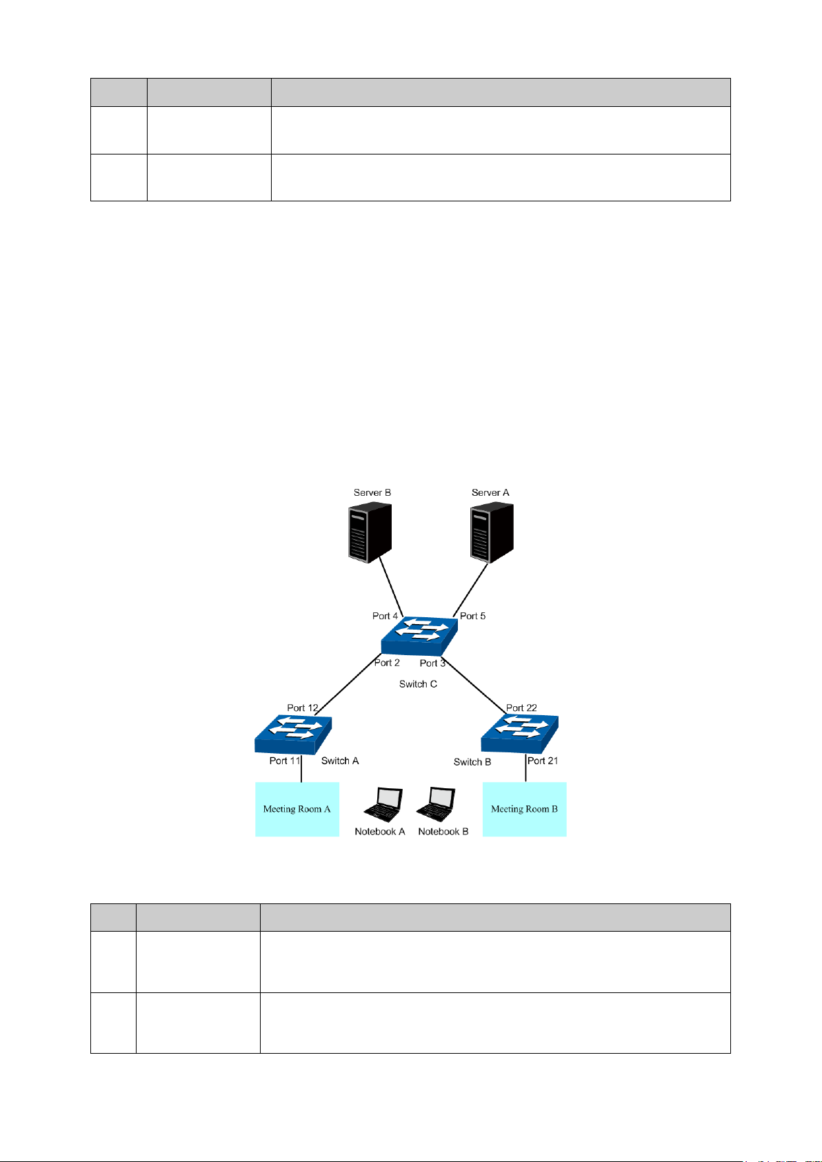
Step Operation Description
Configure the
k Type of the
Required. On VLAN→802.1Q VLAN →Port Config page, configure
Port 12 as GENERAL and TRUNK
Create VLAN10
Required. On VLAN→802.1Q VLAN→VLAN Config page, create a
ning Port 11 and Port 12, and
2
Create VLAN10 Required. On VLAN→802.1Q VLAN→VLAN Config page, create a
VLAN with its VLAN ID as 10, owning Port 6 and Port 8.
3
Create VLAN20 Required. On VLAN→802.1Q VLAN→VLAN Config page, create a
VLAN with its VLAN ID as 20, owning Port 6 and Port 7.
6.5 Application Example for MAC VLAN
Network Requirements
Switch A and switch B are connected to meeting room A and meeting room B respectively, and
the two rooms are for all departments;
Notebook A and Notebook B, special for meeting room, are of two different departments;
The two departments are in VLAN10 and VLAN20 respectively. The two notebooks can just
access the server of their own departments, that is, Server A and Server B, in the two meeting
rooms;
The MAC address of Notebook A is 00-19-56-8A-4C-71, Notebook B’s MAC address is
00-19-56-82-3B-70.
Network Diagram
Configuration Procedure
Configure Switch A
Step Operation Description
1
Lin
ports
the link type of Port 11 and
respectively.
2
VLAN with its VLAN ID as 10, ow
configure the egress rule of Port 11 as Untag.
81
Page 92

Step Operation Description
Create VLAN20
Required. On VLAN→802.1Q VLAN→VLAN Config page, create a
ID as 20, owning Port 11 and Port 12, and
Configure MAC
On VLAN→MAC VLAN page, create MAC VLAN10 with the MAC
Configure MAC
On VLAN→MAC VLAN page, create MAC VLAN10 with the MAC
Configure the
Link Type of the
page, configure
Port 22 as GENERAL and TRUNK
page, create a
ID as 10, owning Port 21 and Port 22, and
page, create a
ID as 20, owning Port 21 and Port 22, and
page, create MAC VLAN10 with the MAC
page, create MAC VLAN10 with the MAC
Configure the
Link Type of the
page, configure
page, create a
page, create a
3
VLAN with its VLAN
configure the egress rule of Port 11 as Untag.
4
VLAN 10
address as 00-19-56-8A-4C-71.
5
VLAN 20
Configure Switch B
address as 00-19-56-82-3B-70.
Step Operation Description
1
Required. On VLAN→802.1Q VLAN →Port Config
the link type of Port 21 and
ports
respectively.
2 Create VLAN10 Required. On VLAN→802.1Q VLAN→VLAN Config
VLAN with its VLAN
configure the egress rule of Port 21 as Untag.
3 Create VLAN20 Required. On VLAN→802.1Q VLAN→VLAN Config
VLAN with its VLAN
configure the egress rule of Port 21 as Untag.
4 Configure MAC
VLAN 10
5 Configure MAC
VLAN 20
Configure Switch C
On VLAN→MAC VLAN
address as 00-19-56-8A-4C-71.
On VLAN→MAC VLAN
address as 00-19-56-82-3B-70.
Step Operation Description
1
Required. On VLAN→802.1Q VLAN →Port Config
the link type of Port 2 and Port 3 as GENERAL, and configure the link
ports
type of Port 4 and Port 5 as ACCESS.
2 Create VLAN10 Required. On VLAN→802.1Q VLAN→VLAN Config
VLAN with its VLAN ID as 10, owning Port 2, Port 3 and Port 5,
3 Create VLAN20 Required. On VLAN→802.1Q VLAN→VLAN Config
VLAN with its VLAN ID as 20, owning Port 2, Port 3 and Port 4,
6.6 Application Example for Protocol VLAN
Network Requirements
Department A is connected to the company LAN via Port12 of switch A;
Department A has IP host and AppleTalk host;
IP host, in VLAN10, is served by IP server while AppleTalk host is served by AppleTalk server;
Switch B is connected to IP server and AppleTalk server.
82
Page 93
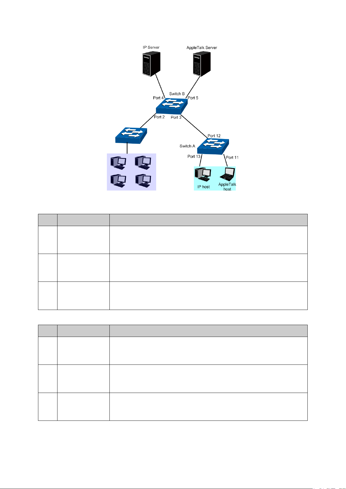
Network Diagram
Configure the
Link Type of the
page, configure
page, create a
2 and Port 13, and
page, create a
ID as 20, owning Port 11 and Port 12, and
Configure the
Link Type of the
page, configure
page, create a
page, create a
Configuration Procedure
Configure Switch A
Step Operation Description
1
Required. On VLAN→802.1Q VLAN →Port Config
the link type of Port 11 and Port 13 as ACCESS, and configure the link
ports
type of Port 12 as GENERAL.
2 Create VLAN10 Required. On VLAN→802.1Q VLAN→VLAN Config
VLAN with its VLAN ID as 10, owning Port 1
configure the egress rule of Port 12 as Untag.
3 Create VLAN20 Required. On VLAN→802.1Q VLAN→VLAN Config
VLAN with its VLAN
configure the egress rule of Port 12 as Untag.
Configure Switch B
Step Operation Description
1
Required. On VLAN→802.1Q VLAN →Port Config
the link type of Port 4 and Port 5 as ACCESS, and configure the link
ports
type of Port 3 as GENERAL.
2 Create VLAN10 Required. On VLAN→802.1Q VLAN→VLAN Config
VLAN with its VLAN ID as 10, owning Port 3 and Port 4, and configure
the egress rule of Port 3 as Untag.
3 Create VLAN20 Required. On VLAN→802.1Q VLAN→VLAN Config
VLAN with its VLAN ID as 20, owning Port 3 and Port 5, and configure
the egress rule of Port 3 as Untag.
83
Page 94

Step Operation Description
Create Protocol
Create Protocol
Create Protocol
4
Template
Required. On VLAN →Protocol VLAN →Protocol Template page,
configure the protocol template practically. E.g. the IP network packets
are encapsulated in Ethernet II format and its Ether Type is 0800; the
AppleTalk network packets are encapsulated in SNAP format and its
PID is 809B.
5
VLAN 10
6
VLAN 20
On VLAN →Protocol VLAN →Protocol Group page, create protocol
VLAN 10 with Protocol as IP and tick Port 3.
On VLAN →Protocol VLAN →Protocol Group page, create protocol
VLAN 20 with Protocol as AppleTalk and tick Port 3.
6.7 GVRP
GVRP (GARP VLAN Registration Protocol) is an implementation of GARP (generic attribute
registration protocol). GVRP allows the switch to automatically add or remove the VLANs via the
dynamic VLAN registration information and propagate the local VLAN registration information to
other switches, without having to individually configure each VLAN.
GARP
GARP provides the mechanism to assist the switch members in LAN to deliver, propagate and
register the information among the members. GARP itself does not work as the entity among the
devices. The application complied with GARP is called GARP implementation, and GVRP is the
implementation of GARP. When GARP is implemented on a port of device, the port is called
GARP entity.
The information exchange between GARP entities is completed by messages. GARP defines the
messages into three types: Join, Leave and LeaveAll.
Join Message: When a GARP entity expects other switches to register certain attribute
•
information of its own, it sends out a Join message. And when receiving the Join message
from the other entity or configuring some attributes statically, the device also sends out a Join
message in order to be registered by the other GARP entities.
Leave Message: When a GARP entity expects other switches to deregister certain attribute
•
information of its own, it sends out a Leave message. And when receiving the Leave message
from the other entity or deregistering some attributes statically, the device also sends out a
Leave message.
•
LeaveAll Message: Once a GARP entity starts up, it starts the LeaveAll timer. After the timer
times out, the GARP entity sends out a LeaveAll message. LeaveAll message is to deregister
all the attribute information so as to enable the other GARP entities to re-register attribute
information of their own.
Through message exchange, all the attribute information to be registered can be propagated to all
the switches in the same switched network.
The interval of GARP messages is controlled by timers. GARP defines the following timers:
• Hold Timer: When a GARP entity receives a piece of registration information, it does not send
out a Join message immediately. Instead, to save the bandwidth resources, it starts the Hold
timer, puts all registration information it receives before the timer times out into one Join
message and sends out the message after the timer times out.
84
Page 95

• Join Timer: To transmit the Join messages reliably to other entities, a GARP entity sends
each Join message two times. The Join timer is used to define the interval between the two
sending operations of each Join message.
• Leave Timer: When a GARP entity expects to deregister a piece of attribute information, it
sends out a Leave message. Any GARP entity receiving this message starts its Leave timer,
and deregisters the attribute information if it does not receives a Join message again before
the timer times out.
• LeaveAll Timer: Once a GARP entity starts up, it starts the LeaveAll timer, and sends out a
LeaveAll message after the timer times out, so that other GARP entities can re-register all the
attribute information on this entity. After that, the entity restarts the LeaveAll timer to begin a
new cycle.
GVRP
GVRP, as an implementation of GARP, maintains dynamic VLAN registration information and
propagates the information to other switches by adopting the same mechanism of GARP.
After the GVRP feature is enabled on a switch, the switch receives the VLAN registration
information from other switches to dynamically update the local VLAN registration information,
including VLAN members, ports through which the VLAN members can be reached, and so on.
The switch also propagates the local VLAN registration information to other switches so that all the
switching devices in the same switched network can have the same VLAN information. The VLAN
registration information includes not only the static registration information configured locally, but
also the dynamic registration information, which is received from other switches.
In this switch, only the port with TRUNK link type can be set as the GVRP application entity to
maintain the VLAN registration information. GVRP has the following three port registration modes:
Normal, Fixed, and Forbidden.
• Normal: In this mode, a port can dynamically register/deregister a VLAN and propagate the
dynamic/static VLAN information.
• Fixed: In this mode, a port cannot register/deregister a VLAN dynamically. It only propagates
static VLAN information. That is, the port in Fixed mode only permits the packets of its static
VLAN to pass.
• Forbidden: In this mode, a port cannot register/deregister VLANs. It only propagates VLAN 1
information. That is, the port in Forbidden mode only permits the packets of the default VLAN
(namely VLAN 1) to pass.
85
Page 96

GVRP:
Port Sel
select the corresponding entry based
Select:
Port:
Status:
or the port. The port type should be
Registration
Mode:
In this mode, a port can dynamically register/deregister
In this mode, a port cannot register/deregister a VLAN
Choose the menu VLAN →GVRP to load the following page.
Figure 6-11 GVRP Config
Note:
If the GVRP feature is enabled for a member port of LAG, please ensure all the member ports of
this LAG are set to be in the same status and registration mode.
The following entries are displayed on this screen:
Global Config
Allows you to Enable/Disable the GVRP function.
Port Config
ect: Click the Select button to quick-
on the port number you entered.
Select the desired port for configuration. It is multi-optional.
Displays the port number.
Enable/Disable the GVRP feature f
set to TRUNK before enabling the GVRP feature.
Select the Registration Mode for the port.
• Normal:
a VLAN and propagate the dynamic/static VLAN information.
• Fixed:
dynamically. It only propagates static VLAN information.
86
Page 97

• Forbidden: In this mode, a port cannot register/deregister
LeaveAll Timer:
Join Timer:
Leave Timer:
message will start its Leave timer, and deregister the attribute
timer times out. The Leave Timer ranges from 60 to 3000
LAG:
Configure the registration
page, configure the
VLANs. It only propagates VLAN 1 information.
Once the LeaveAll Timer is set, the port with GVRP enabled can send
a LeaveAll message after the timer times out, so that other GARP
ports can re-register all the attribute information. After that, the
LeaveAll timer will start to begin a new cycle. The LeaveAll Timer
ranges from 1000 to 30000 centiseconds.
To guarantee the transmission of the Join messages, a GARP port
sends each Join message two times. The Join Timer is used to define
the interval between the two sending operations of each Join
message. The Join Timer ranges from 20 to 1000 centiseconds.
Once the Leave Timer is set, the GARP port receiving a Leave
information if it does not receive a Join message again before the
centiseconds.
Displays the LAG to which the port belongs.
Note:
LeaveAll Timer >= 10* Leave Timer, Leave Timer >= 2*Join Timer
Configuration Procedure:
Step Operation Description
1 Set the link type for port. Required. On the VLAN →802.1Q VLAN →Port Config
page, set the link type of the port to be TRUNK.
2 Enable GVRP function. Required. On the VLAN →GVRP page, enable GVRP
function.
3
mode and the timers for the
port.
Required. On the VLAN →GVRP
parameters of ports based on actual applications.
Return to CONTENTS
87
Page 98

Chapter 7 Spanning Tree
STP (Spanning Tree Protocol), subject to IEEE 802.1D standard, is to disbranch a ring network in
the Data Link layer in a local network. Devices running STP discover loops in the network and block
ports by exchanging information, in that way, a ring network can be disbranched to form a
tree-topological ring-free network to prevent packets from being duplicated and forwarded endlessly
in the network.
BPDU (Bridge Protocol Data Unit) is the protocol data that STP and RSTP use. Enough
information is carried in BPDU to ensure the spanning tree generation. STP is to determine the
topology of the network via transferring BPDUs between devices.
To implement spanning tree function, the switches in the network transfer BPDUs between each
other to exchange information and all the switches supporting STP receive and process the
received BPDUs. BPDUs carry the information that is needed for switches to figure out the
spanning tree.
STP Elements
Bridge ID(Bridge Identifier): Indicates the value of the priority and MAC address of the bridge.
Bridge ID can be configured and the switch with the lower bridge ID has the higher priority.
Root Bridge: Indicates the switch has the lowest bridge ID. Configure the best PC in the ring
network as the root bridge to ensure best network performance and reliability.
Designated Bridge: Indicates the switch has the lowest path cost from the switch to the root
bridge in each network segment. BPDUs are forwarded to the network segment through the
designated bridge. The switch with the lowest bridge ID will be chosen as the designated bridge.
Root Path Cost: Indicates the sum of the path cost of the root port and the path cost of all the
switches that packets pass through. The root path cost of the root bridge is 0.
Bridge Priority: The bridge priority can be set to a value in the range of 0~32768. The lower value
priority has the higher priority. The switch with the higher priority has more chance to be chosen as
the root bridge.
Root Port: Indicates the port that has the lowest path cost from this bridge to the Root Bridge and
forwards packets to the root.
Designated Port: Indicates the port that forwards packets to a downstream network segment or
switch.
Port Priority: The port priority can be set to a value in the range of 0~255. The lower value priority
has the higher priority. The port with the higher priority has more chance to be chosen as the root
port.
Path Cost: Indicates the parameter for choosing the link path by STP. By calculating the path cost,
STP chooses the better links and blocks the redundant links so as to disbranch the ring-network to
form a tree-topological ring-free network.
The following network diagram shows the sketch map of spanning tree. Switch A, B and C are
connected together in order. After STP generation, switch A is chosen as root bridge, the path from
port 2 to port 6 is blocked.
Bridge: Switch A is the root bridge in the whole network; switch B is the designated bridge of
switch C.
Port: Port 3 is the root port of switch B and port 5 is the root port of switch C; port 1 is the
designated port of switch A and port 4 is the designated port of switch B; port 6 is the blocked
port of switch C.
88
Page 99

Figure 7-1 Basic STP diagram
STP Timers
Hello Time:
Hello Time ranges from 1 to 10 seconds. It specifies the interval to send BPDU packets. It is used
to test the links.
Max. Age:
Max. Age ranges from 6 to 40 seconds. It specifies the maximum time the switch can wait without
receiving a BPDU before attempting to reconfigure.
Forward Delay:
Forward Delay ranges from 4 to 30 seconds. It specifies the time for the port to transit its state
after the network topology is changed.
When the STP regeneration caused by network malfunction occurs, the STP structure will get
some corresponding change. However, as the new configuration BPDUs cannot be spread in the
whole network at once, the temporal loop will occur if the port transits its state immediately.
Therefore, STP adopts a state transit mechanism, that is, the new root port and the designated
port begins to forward data after twice forward delay, which ensures the new configuration BPDUs
are spread in the whole network.
BPDU Comparing Principle in STP mode
Assuming two BPDUs: BPDU X and BPDU Y
If the root bridge ID of X is smaller than that of Y, X is superior to Y.
If the root bridge ID of X equals that of Y, but the root path cost of X is smaller than that of Y, X is
superior to Y.
If the root bridge ID and the root path cost of X equal those of Y, but the bridge ID of X is smaller
than that of Y, X is superior to Y.
If the root bridge ID, the root path cost and bridge ID of X equal those of Y, but the port ID of X is
smaller than that of Y, X is superior to Y.
STP Generation
In the beginning
In the beginning, each switch regards itself as the root, and generates a configuration BPDU for
each port on it as a root, with the root path cost being 0, the ID of the designated bridge being that
of the switch, and the designated port being itself.
89
Page 100

the port itself, the switch discards the BPDU and does not change the BPDU of
the
switch replaces the BPDU of the port with the received one and compares it with
Using the root port BPDU and the root path cost, the switch generates a
Root path is replaced with the sum of the root path cost of the root port and
The switch compares the resulting BPDU with the BPDU of the desired port
If the resulting BPDU takes the precedence over the BPDU of the port, the
s chosen as the designated port and the BPDU of this port is replaced
If the BPDU of this port takes the precedence over the resulting BPDU, the
the port is blocked. The port only can
Comparing BPDUs
Each switch sends out configuration BPDUs and receives a configuration BPDU on one of its ports
from another switch. The following table shows the comparing operations.
Step Operation
1 If the priority of the BPDU received on the port is lower than that of the BPDU if of
the port.
2 If the priority of the BPDU is higher than that of the BPDU of the port itself,
those of other ports on the switch to obtain the one with the highest priority.
Table 7-1 Comparing BPDUs
Selecting the root bridge
The root bridge is selected by BPDU comparing. The switch with the smallest root ID is chosen as
the root bridge.
Selecting the root port and designate port
The operation is taken in the following way:
Step Operation
1 For each switch (except the one chosen as the root bridge) in a network, the port
that receives the BPDU with the highest priority is chosen as the root port of the
switch.
2
designated port BPDU for each of its ports.
Root ID is replaced with that of the root port;
the path cost between this port and the root port;
The ID of the designated bridge is replaced with that of the switch;
The ID of the designated port is replaced with that of the port.
3
whose role you want to determine.
port i
with the resulting BPDU. The port regularly sends out the resulting BPDU;
BPDU of this port is not replaced and
receive BPDUs.
Table 7-2 Selecting root port and designated port
Tips:
In a STP with stable topology, only the root port and designated port can forward data, and the
other ports are blocked. The blocked ports only can receive BPDUs.
RSTP (Rapid Spanning Tree Protocol), evolved from the 802.1D STP standard, enable Ethernet
ports to transit their states rapidly. The premises for the port in the RSTP to transit its state rapidly
are as follows.
90
 Loading...