

Page 1
REV2.0.0
191001
TL-SG2216/TL-SG2424/TL-SG2424P/TL-SG2452
Gigabit Smart Switch
1094
Page 2

COPYRIGHT & TRADEMARKS
Specifications are subject to change without notice. is a registered trademark of
TP-LINK TECHNOLOGIES CO., LTD. Other brands and product names are trademarks or
registered trademarks of their respective holders.
No part of the specifications may be reproduced in any form or by any means or used to make any
derivative such as translation, transformation, or adaptation without permission from TP-LINK
TECHNOLOGIES CO., LTD. Copyright © 2014 TP-LINK TECHNOLOGIES CO., LTD. All rights
reserved.
http://www.tp-link.com
I
Page 3

CONTENTS
Preface .............................................................................................................. 1
Chapter 1 Using the CLI ....................................................................................... 4
1.1 Accessing the CLI ............................................................................................................... 4
1.1.1. Logon by Telnet ................................................................................................... 4
1.1.2. Logon by SSH ..................................................................................................... 5
1.2 CLI Command Modes ........................................................................................................ 11
1.3 Security Levels .................................................................................................................. 13
1.4 Conventions ...................................................................................................................... 13
1.4.1 Format Conventions ............................................................................................... 13
1.4.2 Special Characters .................................................................................................. 14
1.4.3 Parameter Format ................................................................................................... 14
Chapter 2 User Interface .................................................................................... 15
enable ...................................................................................................................................... 15
service password-encryption .................................................................................................. 15
enable password ..................................................................................................................... 16
enable secret ........................................................................................................................... 17
disable ..................................................................................................................................... 18
configure .................................................................................................................................. 18
exit ........................................................................................................................................... 18
end........................................................................................................................................... 19
history ...................................................................................................................................... 19
history clear ............................................................................................................................. 20
Chapter 3 IEEE 802.1Q VLAN Commands ........................................................ 21
vlan .......................................................................................................................................... 21
interface vlan ........................................................................................................................... 21
name ....................................................................................................................................... 22
switchport general allowed vlan .............................................................................................. 22
switchport pvid ........................................................................................................................ 23
show vlan summary ................................................................................................................ 23
show vlan brief ........................................................................................................................ 24
show vlan ................................................................................................................................ 24
show interface switchport ........................................................................................................ 25
Chapter 4 Voice VLAN Commands .................................................................... 26
II
Page 4

voice vlan ................................................................................................................................ 26
voice vlan aging time ............................................................................................................... 26
voice vlan priority .................................................................................................................... 27
voice vlan mac-address .......................................................................................................... 27
switchport voice vlan mode ..................................................................................................... 28
switchport voice vlan security ................................................................................................. 29
show voice vlan ....................................................................................................................... 29
show voice vlan oui ................................................................................................................. 30
show voice vlan switchport ..................................................................................................... 30
Chapter 5 Etherchannel Commands ................................................................. 32
channel-group ......................................................................................................................... 32
port-channel load-balance ...................................................................................................... 33
lacp system-priority ................................................................................................................. 33
lacp port-priority ...................................................................................................................... 34
show etherchannel .................................................................................................................. 34
show etherchannel load-balance ............................................................................................ 35
show lacp ................................................................................................................................ 35
show lacp sys-id ...................................................................................................................... 36
Chapter 6 User Management Commands ......................................................... 37
user name (password) ............................................................................................................ 37
user name (secret) .................................................................................................................. 38
user access-control ip-based .................................................................................................. 39
user access-control mac-based .............................................................................................. 40
user access-control port-based............................................................................................... 40
user max-number .................................................................................................................... 41
user idle-timeout ...................................................................................................................... 42
show user account-list............................................................................................................. 42
show user configuration .......................................................................................................... 43
Chapter 7 System Log Commands .................................................................... 44
logging buffer ........................................................................................................................... 44
logging file flash ...................................................................................................................... 45
logging file flash frequency ..................................................................................................... 45
logging file flash level .............................................................................................................. 46
clear logging ............................................................................................................................ 46
logging host index ................................................................................................................... 47
show logging local-config ........................................................................................................ 48
III
Page 5

show logging loghost ............................................................................................................... 48
show logging buffer ................................................................................................................. 49
show logging flash ................................................................................................................... 49
Chapter 8 SSH Commands................................................................................. 51
ip ssh server ............................................................................................................................ 51
ip ssh version .......................................................................................................................... 51
ip ssh timeout .......................................................................................................................... 52
ip ssh max-client ..................................................................................................................... 52
ip ssh download ...................................................................................................................... 53
show ip ssh .............................................................................................................................. 53
Chapter 9 SSL Commands ................................................................................. 56
ip http secure-server ............................................................................................................... 56
ip http secure-server download certificate .............................................................................. 56
ip http secure-server download key ........................................................................................ 57
show ip http secure-server ...................................................................................................... 58
Chapter 10 MAC Address Commands ................................................................. 59
mac address-table static ......................................................................................................... 59
mac address-table aging-time ................................................................................................. 60
mac address-table filtering ...................................................................................................... 60
mac address-table max-mac-count......................................................................................... 61
show mac address-table ......................................................................................................... 62
show mac address-table aging-time ....................................................................................... 62
show mac address-table max-mac-count interface gigabitEthernet ...................................... 63
show mac address-table interface gigabitEthernet ................................................................. 63
show mac address-table count ............................................................................................... 64
show mac address-table address ........................................................................................... 64
show mac address-table vlan ................................................................................................. 65
Chapter 11 System Commands ........................................................................... 66
system-time manual ................................................................................................................ 66
system-time ntp ....................................................................................................................... 66
system-time dst predefined ..................................................................................................... 68
system-time dst date ............................................................................................................... 68
system-time dst recurring ........................................................................................................ 69
hostname ................................................................................................................................. 71
location .................................................................................................................................... 71
IV
Page 6

contact-info .............................................................................................................................. 72
ip management-vlan ................................................................................................................ 72
ip address ................................................................................................................................ 73
ip address-alloc dhcp .............................................................................................................. 73
ip address-alloc bootp ............................................................................................................. 74
reset ........................................................................................................................................ 74
reboot ...................................................................................................................................... 75
copy running-config startup-config .......................................................................................... 75
copy startup-config tftp ............................................................................................................ 75
copy tftp startup-config ............................................................................................................ 76
firmware upgrade .................................................................................................................... 77
ping .......................................................................................................................................... 77
tracert ...................................................................................................................................... 78
show system-info .................................................................................................................... 79
show running-config ................................................................................................................ 80
show system-time ................................................................................................................... 80
show system-time dst .............................................................................................................. 80
show system-time ntp ............................................................................................................. 81
show cable-diagnostics interface gigabitEthernet .................................................................. 81
Chapter 12 IPv6 Address Configuration Commands ......................................... 83
ipv6 enable .............................................................................................................................. 83
ipv6 address autoconfig .......................................................................................................... 83
ipv6 address link-local ............................................................................................................. 84
ipv6 address dhcp ................................................................................................................... 84
ipv6 address ra ........................................................................................................................ 85
ipv6 address eui-64 ................................................................................................................. 86
ipv6 address ............................................................................................................................ 86
show ipv6 interface vlan .......................................................................................................... 87
Chapter 13 Ethernet Configuration Commands ................................................. 88
interface gigabitEthernet ......................................................................................................... 88
interface range gigabitEthernet ............................................................................................... 88
description ............................................................................................................................... 89
shutdown ................................................................................................................................. 89
flow-control .............................................................................................................................. 90
media-type ............................................................................................................................... 90
duplex ...................................................................................................................................... 91
V
Page 7

speed ....................................................................................................................................... 91
storm-control broadcast .......................................................................................................... 92
storm-control multicast ............................................................................................................ 93
storm-control unicast ............................................................................................................... 95
storm-control rate .................................................................................................................... 96
bandwidth ................................................................................................................................ 97
clear counters .......................................................................................................................... 97
show interface status .............................................................................................................. 98
show interface counters .......................................................................................................... 98
show interface description ...................................................................................................... 99
show interface flowcontrol ....................................................................................................... 99
show interface configuration ................................................................................................. 100
show storm-control ................................................................................................................ 100
show bandwidth..................................................................................................................... 101
Chapter 14 QoS Commands............................................................................... 102
qos ......................................................................................................................................... 102
qos cos .................................................................................................................................. 102
qos dscp ................................................................................................................................ 103
qos queue cos-map ............................................................................................................... 104
qos queue dscp-map ............................................................................................................. 104
qos queue mode ................................................................................................................... 106
show qos interface ................................................................................................................ 107
show qos cos-map ................................................................................................................ 108
show qos dscp-map .............................................................................................................. 108
show qos queue mode .......................................................................................................... 108
show qos status..................................................................................................................... 109
Chapter 15 Port Mirror Commands .................................................................... 110
monitor session destination interface .................................................................................... 110
monitor session source interface ........................................................................................... 111
show monitor session ............................................................................................................. 112
Chapter 16 Port Isolation Commands ................................................................ 113
port isolation ........................................................................................................................... 113
show port isolation interface .................................................................................................. 113
Chapter 17 Loopback Detection Commands ..................................................... 115
loopback-detection(global) ..................................................................................................... 115
VI
Page 8

loopback-detection interval .................................................................................................... 115
loopback-detection recovery-time .......................................................................................... 116
loopback-detection(interface) ................................................................................................. 116
loopback-detection config ...................................................................................................... 117
loopback-detection recover .................................................................................................... 118
show loopback-detection global ............................................................................................. 118
show loopback-detection interface ........................................................................................ 119
Chapter 18 ACL Commands ............................................................................... 120
access-list create .................................................................................................................. 120
mac access-list ...................................................................................................................... 120
access-list standard .............................................................................................................. 121
access-list extended .............................................................................................................. 122
rule......................................................................................................................................... 123
access-list policy name ......................................................................................................... 123
access-list policy action......................................................................................................... 124
access-list bind(interface) ..................................................................................................... 125
access-list bind(vlan) ............................................................................................................. 125
show access-list .................................................................................................................... 126
show access-list policy .......................................................................................................... 126
show access-list bind ............................................................................................................ 127
Chapter 19 DHCP Filtering Commands ............................................................. 128
ip dhcp filtering ...................................................................................................................... 128
ip dhcp filtering trust .............................................................................................................. 128
show ip dhcp filtering ............................................................................................................. 129
show ip dhcp filtering interface .............................................................................................. 129
Chapter 20 PoE Commands ............................................................................... 130
power inline consumption (global) ........................................................................................ 130
power profile .......................................................................................................................... 130
power time-range .................................................................................................................. 131
power holiday ........................................................................................................................ 132
absolute ................................................................................................................................. 133
periodic .................................................................................................................................. 133
holiday ................................................................................................................................... 134
power inline consumption (interface) .................................................................................... 135
power inline priority ............................................................................................................... 135
power inline supply ................................................................................................................ 136
VII
Page 9

power inline profile ................................................................................................................ 136
power inline time-range ......................................................................................................... 137
show power inline .................................................................................................................. 138
show power inline configuration interface ............................................................................. 138
show power inline information interface ................................................................................ 138
show power profile ................................................................................................................ 139
show power holiday ............................................................................................................... 139
show power time-range ......................................................................................................... 140
Chapter 21 MSTP Commands ............................................................................ 141
spanning-tree(global) ............................................................................................................ 141
spanning-tree(interface) ........................................................................................................ 141
spanning-tree common-config .............................................................................................. 142
spanning-tree mode .............................................................................................................. 143
spanning-tree mst configuration ............................................................................................ 144
instance ................................................................................................................................. 144
name ..................................................................................................................................... 145
revision .................................................................................................................................. 145
spanning-tree mst instance ................................................................................................... 146
spanning-tree mst ................................................................................................................. 146
spanning-tree priority ............................................................................................................ 147
spanning-tree tc-defend ........................................................................................................ 148
spanning-tree timer ............................................................................................................... 148
spanning-tree hold-count ...................................................................................................... 149
spanning-tree max-hops ....................................................................................................... 150
spanning-tree bpdufilter ........................................................................................................ 150
spanning-tree bpduguard ...................................................................................................... 151
spanning-tree guard loop ...................................................................................................... 151
spanning-tree guard root ....................................................................................................... 152
spanning-tree guard tc .......................................................................................................... 152
spanning-tree mcheck ........................................................................................................... 153
show spanning-tree active .................................................................................................... 153
show spanning-tree bridge .................................................................................................... 154
show spanning-tree interface ................................................................................................ 154
show spanning-tree interface-security .................................................................................. 155
show spanning-tree mst ........................................................................................................ 156
Chapter 22 IGMP Snooping Commands ........................................................... 157
VIII
Page 10

ip igmp snooping(global) ....................................................................................................... 157
ip igmp snooping(interface) ................................................................................................... 157
ip igmp snooping immediate-leave ....................................................................................... 158
ip igmp snooping drop-unknown ........................................................................................... 158
ip igmp snooping vlan-config ................................................................................................ 159
ip igmp snooping multi-vlan-config ....................................................................................... 160
ip igmp snooping filter add-id ................................................................................................ 161
ip igmp snooping filter(global) ............................................................................................... 162
ip igmp snooping filter(interface) ........................................................................................... 162
ip igmp snooping filter maxgroup .......................................................................................... 163
ip igmp snooping filter mode ................................................................................................. 163
show ip igmp snooping.......................................................................................................... 164
show ip igmp snooping interface........................................................................................... 164
show ip igmp snooping vlan .................................................................................................. 165
show ip igmp snooping multi-vlan ......................................................................................... 166
show ip igmp snooping groups ............................................................................................. 166
show ip igmp snooping filter .................................................................................................. 167
Chapter 23 MLD Snooping Commands ............................................................. 169
ipv6 mld snooping ................................................................................................................. 169
ipv6 mld snooping router-aging-time .................................................................................... 169
ipv6 mld snooping member-aging-time ................................................................................. 170
ipv6 mld snooping report-suppression .................................................................................. 170
ipv6 mld snooping unknown-filter.......................................................................................... 171
ipv6 mld snooping last-listener query-inteval ........................................................................ 171
ipv6 mld snooping last-listener query-count ......................................................................... 172
ipv6 mld snooping multicast-vlan .......................................................................................... 172
ipv6 mld snooping multicast-vlan vlan-id .............................................................................. 173
ipv6 mld snooping vlan.......................................................................................................... 173
ipv6 mld snooping vlan router-aging-time ............................................................................. 174
ipv6 mld snooping vlan member-aging-time ......................................................................... 174
ipv6 mld snooping vlan immediate-leave .............................................................................. 175
ipv6 mld snooping vlan mrouter ............................................................................................ 175
ipv6 mld snooping vlan static ................................................................................................ 176
ipv6 mld snooping querier vlan ............................................................................................. 176
ipv6 mld snooping querier vlan max-response-time ............................................................. 177
ipv6 mld snooping querier vlan query-interval ...................................................................... 178
ipv6 mld snooping querier vlan query-source ....................................................................... 178
IX
Page 11

ipv6 mld snooping filter(global) ............................................................................................. 179
ipv6 mld snooping filter(interface) ......................................................................................... 179
ipv6 mld snooping filter-mode ............................................................................................... 180
ipv6 mld snooping filter-id ..................................................................................................... 180
ipv6 mld snooping max-group ............................................................................................... 181
clear ipv6 mld snooping statistics ......................................................................................... 181
show ipv6 mld snooping ........................................................................................................ 182
show ipv6 mld snooping vlan ................................................................................................ 182
show ipv6 mld snooping static-mcast ................................................................................... 183
show ipv6 mld snooping group ............................................................................................. 183
show ipv6 mld snooping filter ................................................................................................ 183
show ipv6 mld snooping interface ......................................................................................... 184
show ipv6 mld snooping interface filter ................................................................................. 184
show ipv6 mld snooping querier ........................................................................................... 185
show ipv6 mld snooping statistics ......................................................................................... 185
Chapter 24 SNMP Commands ............................................................................ 186
snmp-server .......................................................................................................................... 186
snmp-server view .................................................................................................................. 186
snmp-server group ................................................................................................................ 187
snmp-server user .................................................................................................................. 188
snmp-server community ........................................................................................................ 190
snmp-server host .................................................................................................................. 190
snmp-server engineID ........................................................................................................... 192
snmp-server traps snmp ....................................................................................................... 193
snmp-server traps link-status ................................................................................................ 193
snmp-server traps ................................................................................................................. 194
snmp-server traps mac ......................................................................................................... 195
snmp-server traps vlan .......................................................................................................... 196
rmon history ........................................................................................................................... 196
rmon event ............................................................................................................................ 197
rmon alarm ............................................................................................................................ 198
show snmp-server ................................................................................................................. 200
show snmp-server view......................................................................................................... 200
show snmp-server group ...................................................................................................... 200
show snmp-server user ......................................................................................................... 201
show snmp-server community .............................................................................................. 201
show snmp-server host ......................................................................................................... 202
X
Page 12

show snmp-server engineID ................................................................................................. 202
show rmon history ................................................................................................................. 202
show rmon event ................................................................................................................... 203
show rmon alarm ................................................................................................................... 203
Chapter 25 LLDP Commands ............................................................................. 205
lldp ......................................................................................................................................... 205
lldp hold-multiplier ................................................................................................................. 205
lldp timer ................................................................................................................................ 206
lldp med-fast-count ................................................................................................................ 207
lldp receive ............................................................................................................................ 207
lldp transmit ........................................................................................................................... 208
lldp snmp-trap ........................................................................................................................ 208
lldp tlv-select .......................................................................................................................... 209
lldp med-location ................................................................................................................... 210
lldp med-status ...................................................................................................................... 210
lldp med-tlv-select .................................................................................................................. 211
show lldp ............................................................................................................................... 212
show lldp interface ................................................................................................................ 212
show lldp local-information interface ..................................................................................... 213
show lldp neighbor-information interface .............................................................................. 213
show lldp traffic interface ....................................................................................................... 214
XI
Page 13

Preface
This Guide is intended for network administrator to provide referenced information about CLI
(Command Line Interface). The device mentioned in this Guide stands for
TL-SG2216/TL-SG2424/TL-SG2424P/TL-SG2452 Gigabit Smart Switch.
The five devices of TL-SG2216/TL-SG2424/TL-SG2424P/TL-SG2452 are sharing this Guide. For
simplicity, we will take TL-SG2424 for example throughout this Guide.
Overview of this Guide
Chapter 1: Using the CLI
Provide information about how to use the CLI, CLI Command Modes, Security Levels and some
Conventions.
Chapter 2: User Interface
Provide information about the commands used to switch between five CLI Command Modes.
Chapter 3: IEEE 802.1Q VLAN Commands
Provide information about the commands used for configuring IEEE 802.1Q VLAN.
Chapter 4: Voice VLAN Commands
Provide information about the commands used for configuring Voice VLAN.
Chapter 5: Etherchannel Commands
Provide information about the commands used for configuring LAG (Link Aggregation Group) and
LACP (Link Aggregation Control Protocol).
Chapter 6: User Management Commands
Provide information about the commands used for user management.
Chapter 7: System Log Commands
Provide information about the commands used for configuring system log.
Chapter 8: SSH Commands
Provide information about the commands used for configuring and managing SSH (Security
Shell).
Chapter 9: SSL Commands
Provide information about the commands used for configuring and managing SSL (Secure
Sockets Layer).
Chapter 10: MAC Address Commands
Provide information about the commands used for Address configuration.
1
Page 14

Chapter 11: System Configuration Commands
Provide information about the commands used for configuring the System information and System
IP, reboot and reset the switch, upgrade the switch system and commands used for cable test.
Chapter 12: IPv6 Address Configuration Commands
Provide information about the commands used for configuring the System IPv6 addresses.
Chapter 13: Ethernet Configuration Commands
Provide information about the commands used for configuring the Bandwidth Control, Negotiation
Mode, and Storm Control for enthernet ports.
Chapter 14: QoS Commands
Provide information about the commands used for configuring the QoS function.
Chapter 15: Port Mirror Commands
Provide information about the commands used for configuring the Port Mirror function.
Chapter 16: Port Isolation Commands
Provide information about the commands used for configuring Port Isolation function.
Chapter 17: Loopback Detection Commands
Provide information about the commands used for configuring the Loopback Detection function.
Chapter 18: ACL Commands
Provide information about the commands used for configuring the ACL (Access Control List).
Chapter 19: DHCP Filtering Commands
Provide information about the commands used for configuring the DHCP Filtering function.
Chapter 20: PoE Commands
Provide information about the commands used for configuring PoE function.
Chapter 21: MSTP Commands
Provide information about the commands used for configuring the MSTP (Multiple Spanning Tree
Protocol).
Chapter 22: IGMP Snooping Commands
Provide information about the commands used for configuring the IGMP Snooping (Internet Group
Management Protocol Snooping).
Chapter 23: MLD Snooping Commands
Provide information about the commands used for configuring the MLD Snooping (Multicast
Listener Discovery Snooping).
Chapter 24: SNMP Commands
Provide information about the commands used for configuring the SNMP (Simple Network
Management Protocol) functions.
2
Page 15

Chapter 25: LLDP Commands
Provide information about the commands used for configuring LLDP function.
3
Page 16
Chapter 1 Using the CLI
1.1 Accessing the CLI
You can log on to the switch and access the CLI by logging on to the switch remotely by a Telnet or
SSH connection through an Ethernet port.
1.1.1. Logon by Telnet
To log on to the switch by a Telnet connection, please take the following steps:
1. Click Start → Run to open the Run window, and type in telnet 192.168.0.1 in the prompt Run
window as Figure 1-1 and click OK.
Figure 1-1 Run Window
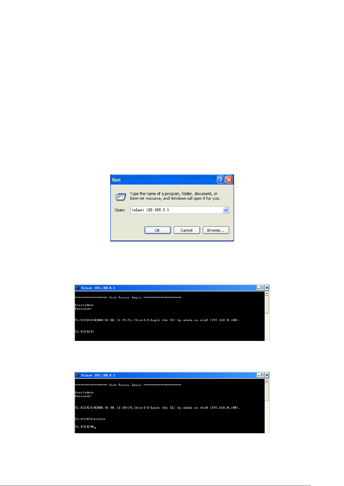
2. Type in the User name and Password (the factory default value for both of them are admin)
and press the Enter button to enter User EXEC Mode , which is shown as Figure 1-2.
Figure 1-2 Log in the Switch
3. Type in enable command to enter Privileged EXEC Mode.
Figure 1-3 Enter into Priviledged EXEC Mode
4
Page 17
1.1.2. Logon by SSH
To log on by SSH, a Putty client software is recommended. There are two authentication modes to
set up an SSH connection:
Password Authentication Mode: It requires username and password, which are both admin by
default.
Key Authentication Mode: It requires a public key for the switch and a private key for the SSH
client software. You can generate the public key and the private key through Putty Key Generator.
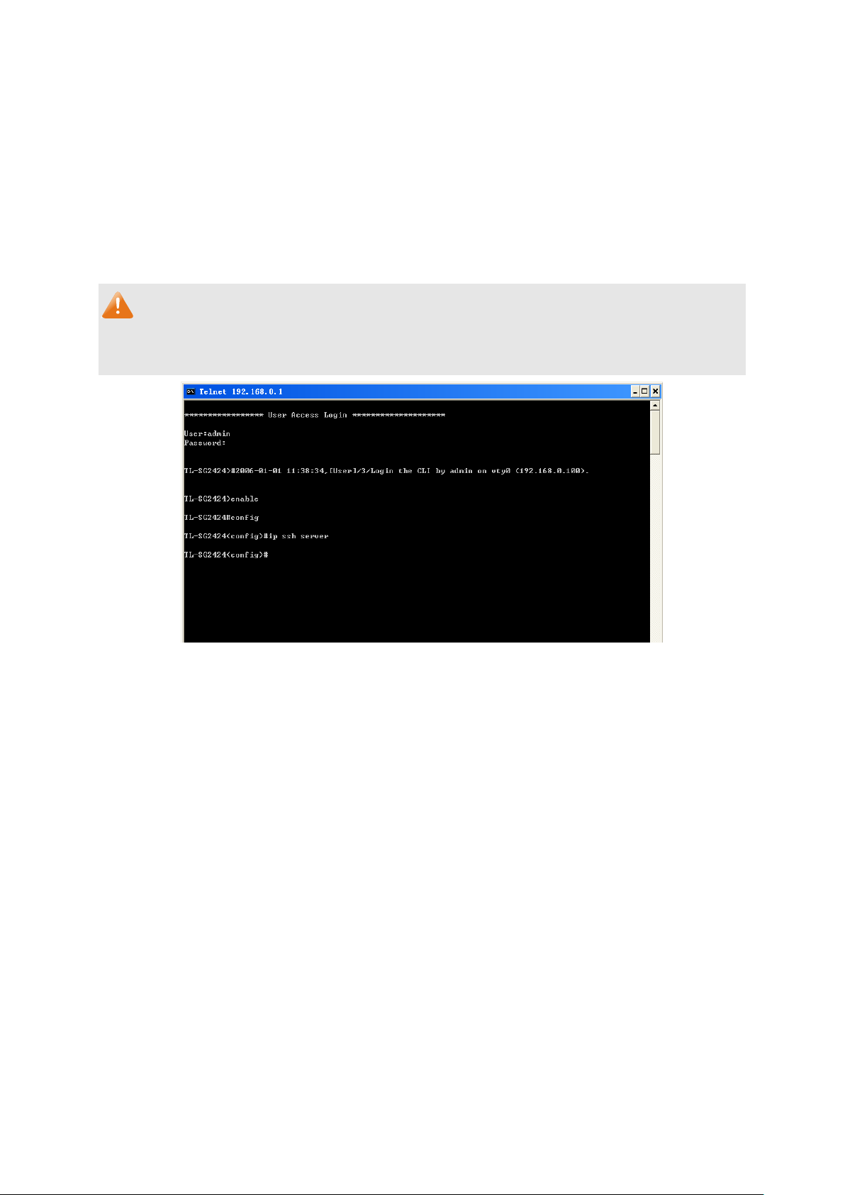
Note:
Before SSH login, please follow the steps shown in Figure 1-4 to enable the SSH function through
Telnet connection.
Figure 1-4 Enable SSH function
Password Authentication Mode
1. Open the software to log on to the interface of PuTTY. Enter the IP address of the switch into
Host Name field; keep the default value 22 in the Port field; select SSH as the Connection
type.
5
Page 18
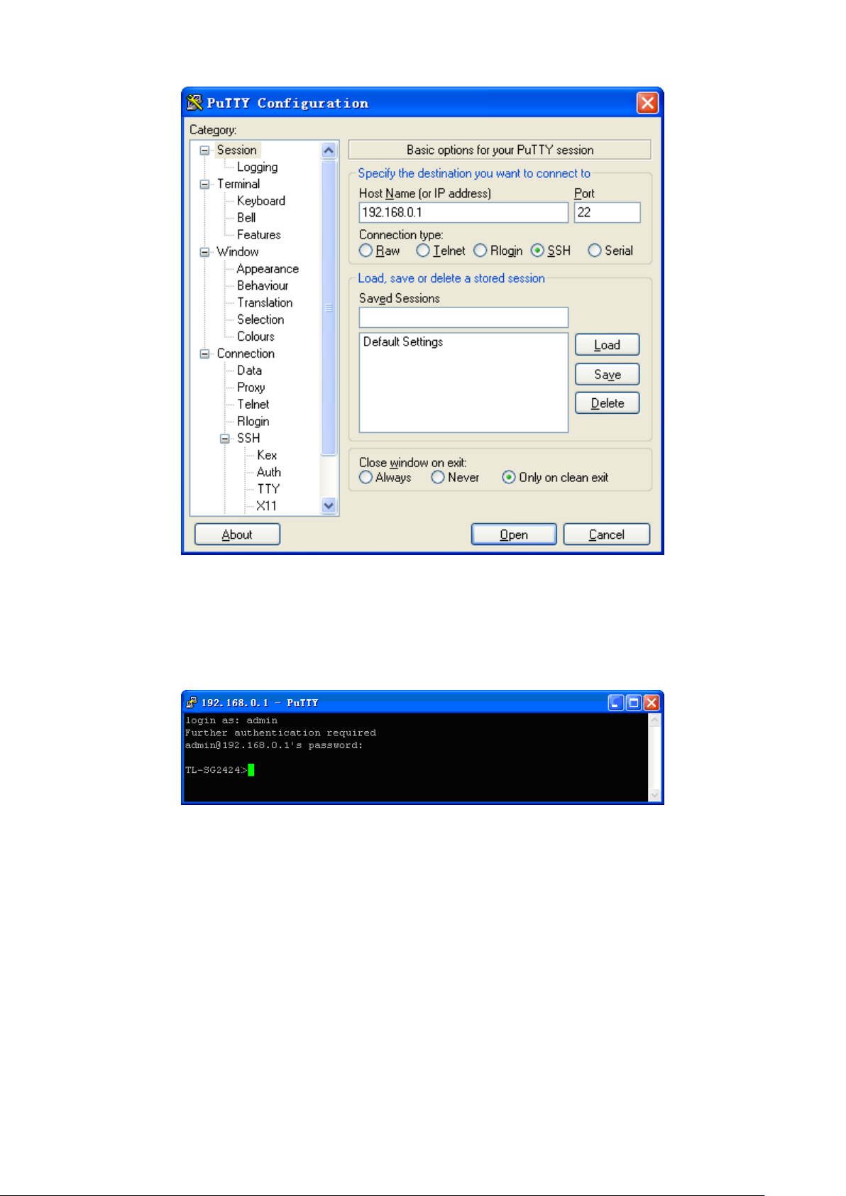
Figure 1-5 SSH Connection Config
2. Click the Open button in the above figure to log on to the switch. Enter the login user name
and password to log on the switch, and then enter enable to enter Privileged EXEC Mode, so
you can continue to configure the switch.
Figure 1-6 Log on the Switch
6
Page 19
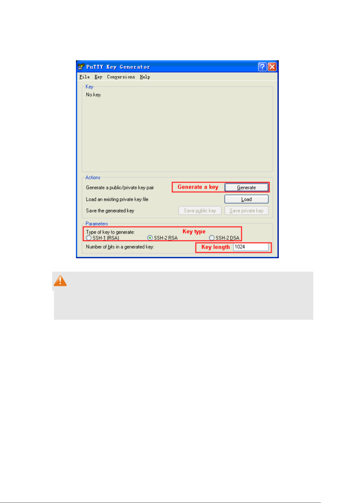
Key Authentication Mode
1. Select the key type and key length, and generate SSH key.
Figure 1-7 Generate SSH Key
Note:
1. The key length is in the range of 256 to 3072 bits.
2. During the key generation, randomly moving the mouse quickly can accelerate the key
generation.
7
Page 20
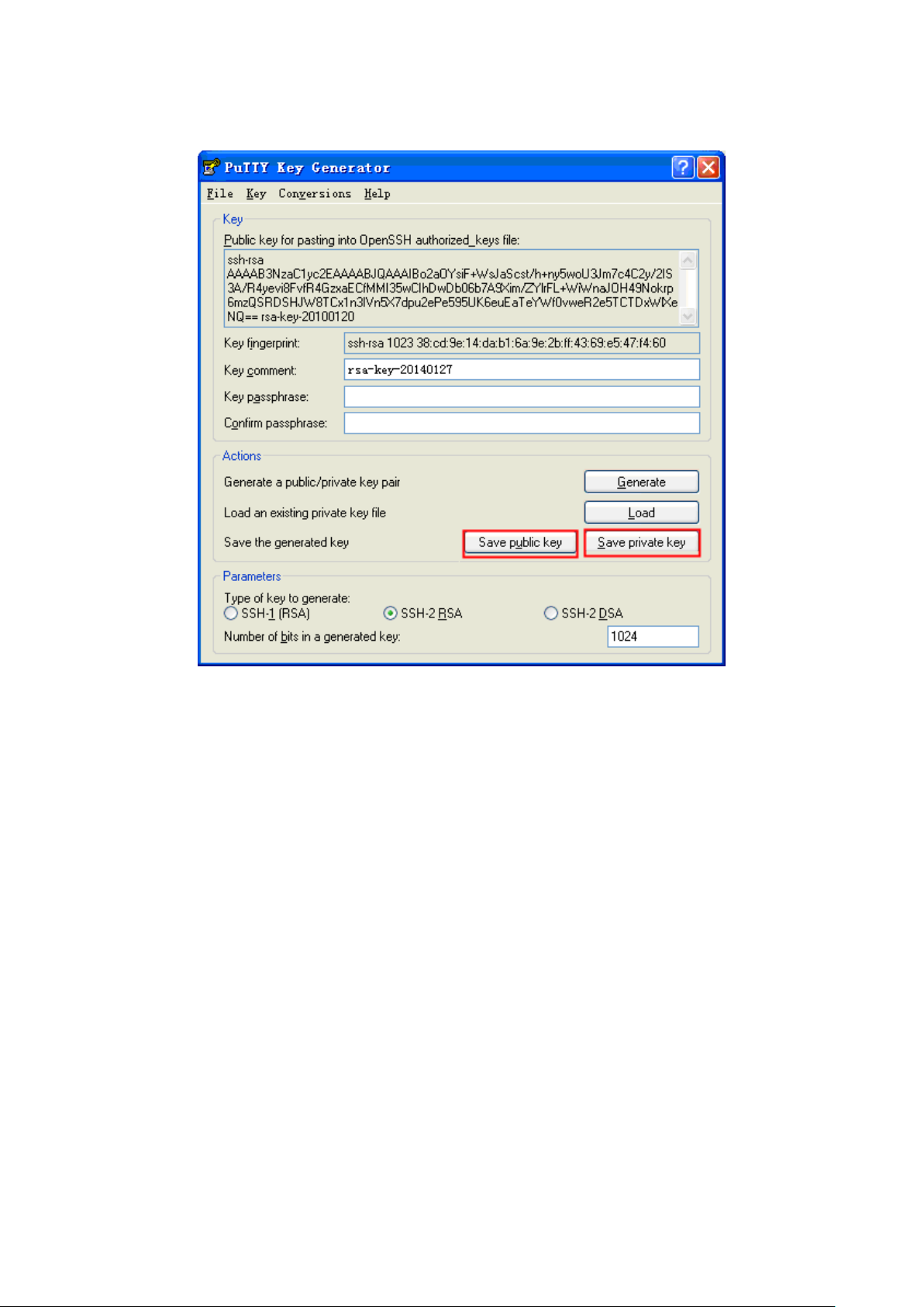
2. After the key is successfully generated, please save the public key and private key to a TFTP
server.
Figure 1-8 Save the Generated Key
3. Log on to the switch by Telnet and download the public key file from the TFTP server to the
switch, as the following figure shows:
8
Page 21
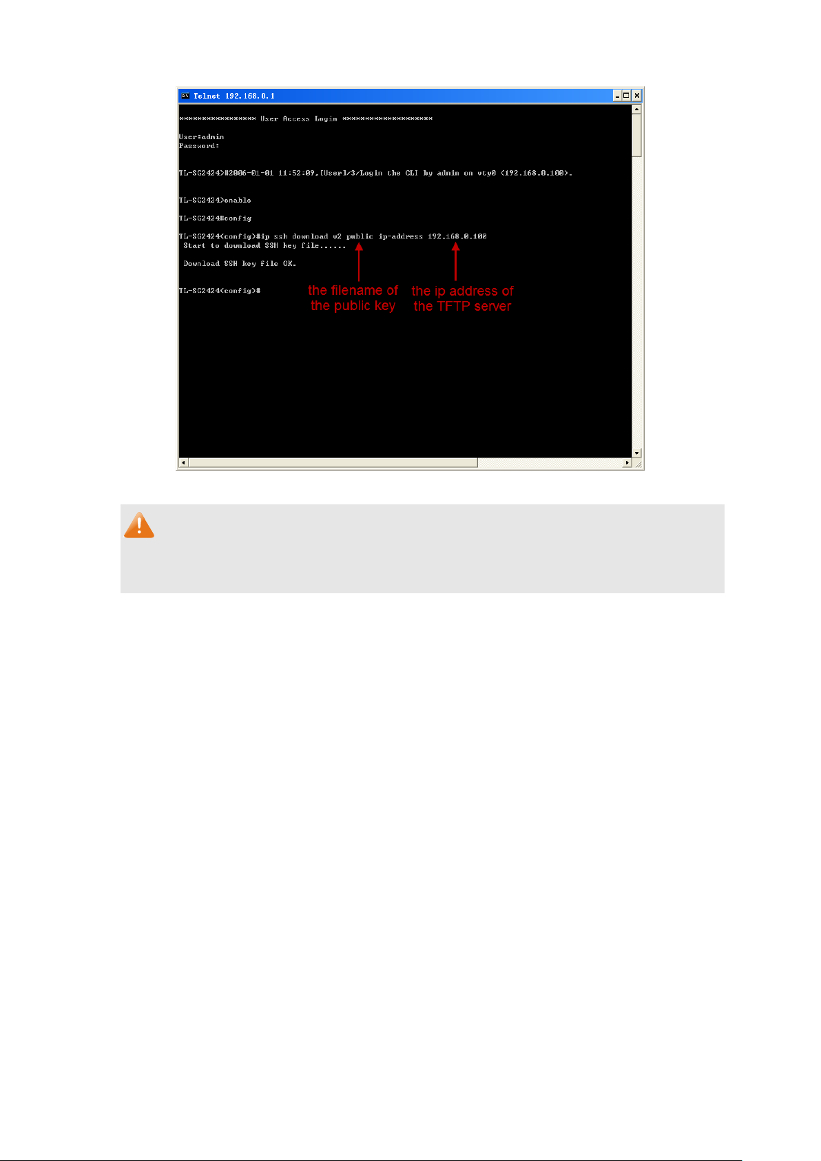
Figure 1-9 Download the Public Key
Note:
1. The key type should accord with the type of the key file.
2. The SSH key downloading can not be interrupted.
4. After the public key is downloaded, please log on to the interface of PuTTY and enter the IP
address for login.
9
Page 22
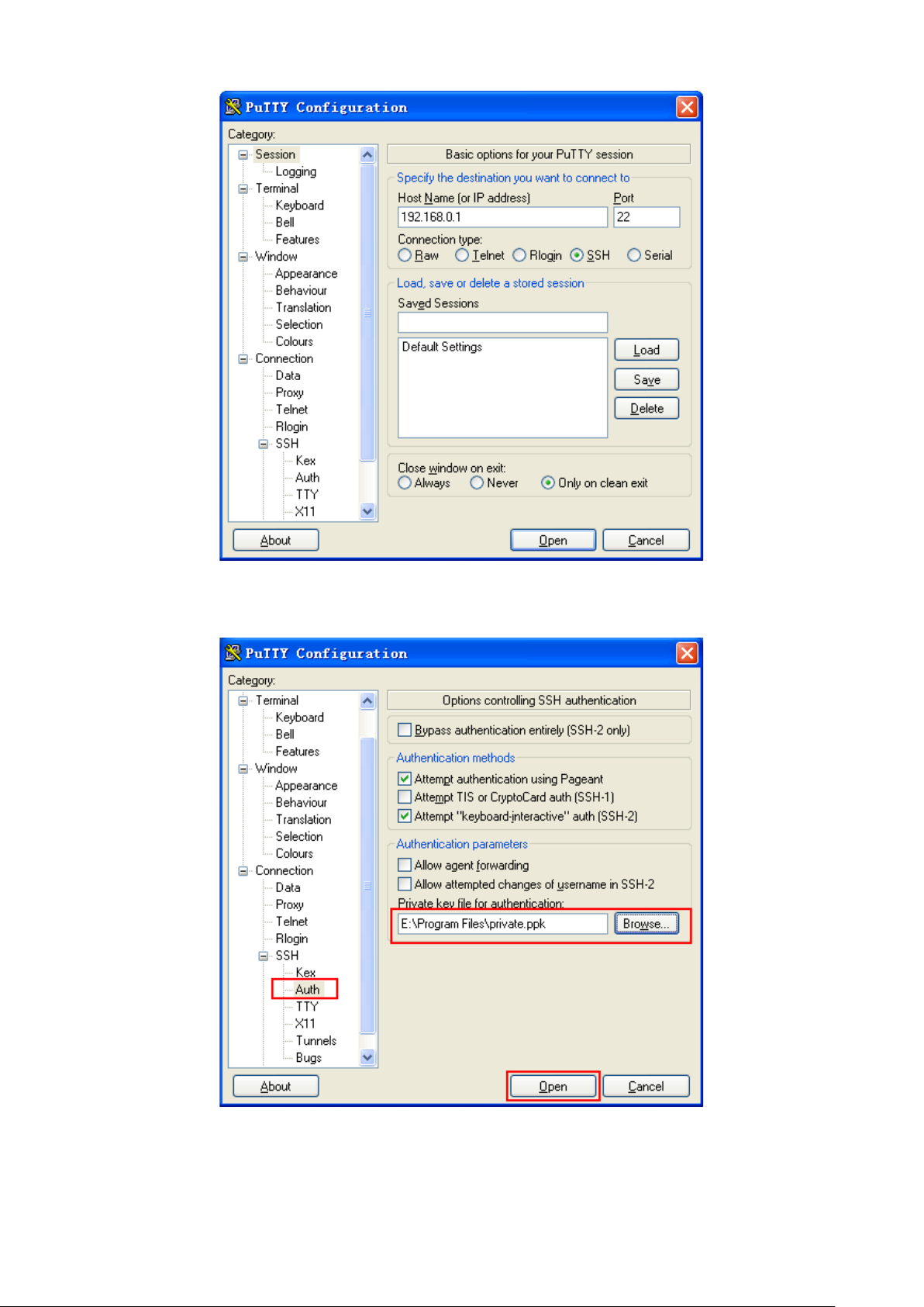
Figure 1-10 SSH Connection Config
5. Click Browse to download the private key file to SSH client software and click Open.
Figure 1-11 Download the Private Key
10
Page 23
Primary mode
once it is
command to
this mode from
command to return to User EXEC
command to
User EXEC Mode
……
VLAN Configuration Mode
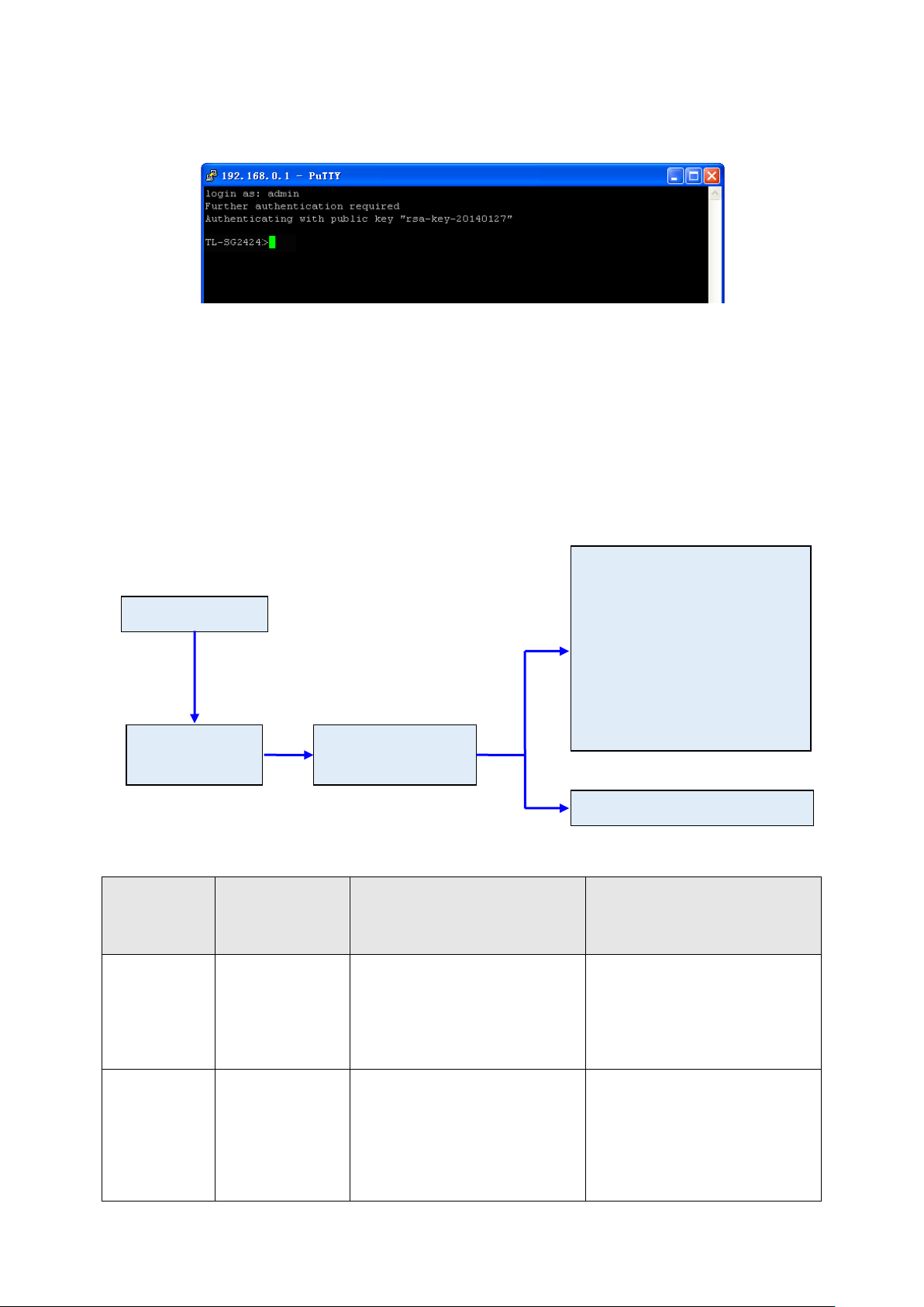
6. After successful authentication, please enter the login user name. If you log on to the switch
without entering password, it indicates that the key has been successfully downloaded.
Figure 1-12 Log on the Switch
1.2 CLI Command Modes
The CLI is divided into different command modes: User EXEC Mode, Privileged EXEC Mode,
Global Configuration Mode, Interface Configuration Mode and VLAN Configuration Mode.
Interface Configuration Mode can also be divided into Interface Ethernet, Interface
link-aggregation and some other modes, which is shown as the following diagram.
Interface Configuration Mode
Interface gigabitEthernet
Interface link-aggregation
Interface range gigabitEthernet
Interface range link-aggregation
Interface vlan
Privileged EXEC
Mode
Global Configuration
Mode
The following table gives detailed information about the Accessing path, Prompt of each mode and
how to exit the current mode and access the next mode.
Mode
User EXEC
Mode
Accessing
Path
connected with the
switch.
Prompt
TL-SG2424>
Logout or Access the next
mode
Use the exit command to
disconnect the switch.
Use the enable
access Privileged EXEC mode.
Privileged
EXEC Mode
Use the enable
command to enter
User EXEC mode.
TL- SG2424#
11
Enter the disable or the exit
mode.
Enter configure
access Global Configuration mode.
Page 24

this mode from
Privileged EXEC
to return to
to access interface Configuration
to access
type number
this mode from
command or press
from Global
command or press
or the #
Mode
Global
Configuration
Mode
Interface
Configuration
Mode
Accessing
Path
Use the configure
command to enter
mode.
Use the interface
command to enter
Global
Configuration
mode.
Prompt
TL- SG2424 (config)#
TL-SG2424 (config-if)#
or
TL-SG2424(config-if-range)#
Logout or Access the next
mode
Use the exit or the end command
or press Ctrl+Z
Privileged EXEC mode.
Use the interface gigabitEthernet
port or interface range
gigabitEthernet port-list command
mode.
Use the vlan vlan-list
VLAN Configuration mode.
Use the end
Ctrl+Z to return to Privileged EXEC
mode.
Enter exit command or the #
command to return to Global
Configuration mode.
A port number must be specified in
the interface command.
VLAN
Configuration
Mode
Note:
1. The user is automatically in User EXEC Mode after the connection between the PC and the
switch is established by a Telnet/SSH connection.
2. Each command mode has its own set of specific commands. To configure some commands,
you should access the corresponding command mode firstly.
Global Configuration Mode: In this mode, global commands are provided, such as the
Interface Configuration Mode: In this mode, users can configure one or several ports,
Use the vlan
vlan-list command
to enter this mode
Configuration
mode.
TL-SG2424 (config-vlan)#
Use the end
Ctrl+Z to return to Privileged EXEC
mode.
Enter the exit command
command to return to Global
configuration mode.
Spanning Tree, Schedule Mode and so on.
different ports corresponds to different commands
a). Interface gigabitEthernet: Configure parameters for an Ethernet port, such as
Duplex-mode, flow control status.
b). Interface range gigabitEthernet: Configure parameters for several Ethernet ports.
12
Page 25

c). Interface link-aggregation: Configure parameters for a link-aggregation, such as
broadcast storm.
d). Interface range link-aggregation: Configure parameters for multi-trunks.
e). Interface vlan: Configure parameters for the vlan-port.
VLAN Configuration Mode: In this mode, users can create a VLAN and add a specified
port to the VLAN.
3. Some commands are global, that means they can be performed in all modes:
show: display all information of switch, for example: statistic information, port information,
VLAN information.
history: Display the commands history.
1.3 Security Levels
This switch’s security is divided into two levels: User level and Admin level.
User level only allows users to do some simple operations in User EXEC Mode; Admin level
allows you to monitor, configure and manage the switch in Privileged EXEC Mode, Global
Configuration Mode, Interface Configuration Mode and VLAN Configuration Mode.
Users get the privilege to the User level once logging in by Telnet/SSH. However, Guest users are
restricted to access the CLI.
Users can enter Privileged EXEC mode from User EXEC mode by using the enable command. In
default case, no password is needed. In Global Configuration Mode, you can configure password
for Admin level by enable password command. Once password is configured, you are required to
enter it to access Privileged EXEC mode.
1.4 Conventions
1.4.1 Format Conventions
The following conventions are used in this Guide:
Items in square brackets [ ] are optional
Items in braces { } are required
Alternative items are grouped in braces and separated by vertical bars. For example: speed
{10 | 100 | 1000 }
Bold indicates an unalterable keyword. For example: show logging
13
Page 26

Normal Font indicates a constant (several options are enumerated and only one can be
selected). For example: mode {dynamic | static | permanent}
Italic Font indicates a variable (an actual value must be assigned). For example: bridge
aging-time aging-time
1.4.2 Special Characters
You should pay attentions to the description below if the variable is a character string:
These six characters ” < > , \ & can not be input.
If a blank is contained in a character string, single or double quotation marks should be used,
for example ’hello world’, ”hello world”, and the words in the quotation marks will be identified
as a string. Otherwise, the words will be identified as several strings.
1.4.3 Parameter Format
Some parameters must be entered in special formats which are shown as follows:
MAC address must be enter in the format of xx:xx:xx:xx:xx:xx
One or several values can be typed for a port-list or a vlan-list using comma to separate. Use
a hyphen to designate a range of values, for instance,1/0/1,1/0/3-5,1/0/7 indicates choosing
port 1/0/1,1/0/3,1/0/4,1/0/5,1/0/7.
14
Page 27

Chapter 2 User Interface
enable
Description
The enable command is used to access Privileged EXEC Mode from User
EXEC Mode.
Syntax
enable
Command Mode
User EXEC Mode
Example
If you have set the password to access Privileged EXEC Mode from User EXEC
Mode:
TL-SG2424>enable
Enter password:
TL-SG2424#
service password-encryption
Description
The service password-encryption command is used to encrypt the password
when the password is defined or when the configuration is written, using the
symmetric encryption algorithm. Encryption prevents the password from being
readable in the configuration file. To disable the global encryption function,
please use no service password-encryption command.
Syntax
service password-encryption
no service password-encryption
Command Mode
Global Configuration Mode
Example
Enable the global encryption function:
TL-SG2424(config)# service password-encryption
15
Page 28

enable password
Description
The enable password command is used to set or change the password for
users to access Privileged EXEC Mode from User EXEC Mode. To remove the
password, please use no enable password command. This command uses the
symmetric encryption.
Syntax
enable password { [ 0 ] password | 7 encrypted-password }
no enable password
Parameter
0 —— Specify the encryption type. 0 indicates that an unencrypted password
will follow. By default, the encryption type is 0.
password —— Super password, a string from 1 to 31 alphanumeric characters
or symbols. The password is case sensitive, allows digits, English letters (case
sensitive), underlines and sixteen special characters ( !$%'()*,-./[]{|} ). By default,
it is empty.
7 —— Indicates a symmetric encrypted password with fixed length will follow.
encrypted-password —— A symmetric encrypted password with fixed length,
which you can copy from another switch’s configuration file. After the encrypted
password is configured, you should use the corresponding unencrypted
password if you re-enter this mode.
Command Mode
Global Configuration Mode
User Guidelines
If the password you configured here is unencrypted and the global encryption
function is enabled in service password-encryption
configuration file will be displayed in the symmetric encrypted form.
, the password in the
Example
Set the super password as “admin” and unencrypted to access Privileged EXEC
Mode from User EXEC Mode:
TL-SG2424(config)#enable password 0 admin
16
Page 29

enable secret
Description
The enable secret command is used to set a secret password, which is using
an MD5 encryption algorithm, for users to access Privileged EXEC Mode from
User EXEC Mode. To return to the default configuration, please use no enable
secret command. This command uses the MD5 encryption.
Syntax
enable secret { [ 0 ] password | 5 encrypted-password }
no enable secret
Parameter
0 —— Specify the encryption type. 0 indicates that an unencrypted password
will follow. By default, the encryption type is 0.
password —— Super password, a string from 1 to 31 alphanumeric characters
or symbols. The password is case sensitive, allows digits, English letters (case
sensitive), underlines and sixteen special characters ( !$%'()*,-./[]{|} ). By default,
it is empty. The password in the configuration file will be displayed in the MD5
encrypted form.
5 —— Indicates an MD5 encrypted password with fixed length will follow.
encrypted-password —— An MD5 encrypted password with fixed length, which
you can copy from another switch’s configuration file. After the encrypted
password is configured, you should use the corresponding unencrypted
password if you re-enter this mode.
Command Mode
Global Configuration Mode
User Guidelines
If both the enable password and enable secret are defined, you must enter the
password set in enable secret.
Example
Set the secret password as “admin” and unencrypted to access Privileged
EXEC Mode from User EXEC Mode. The password will be displayed in the
encrypted form.
TL-SG2424(config)#enable secret 0 admin
17
Page 30

disable
Description
Syntax
Command Mode
Example
The disable command is used to return to User EXEC Mode from Privileged
EXEC Mode.
disable
Privileged EXEC Mode
Return to User EXEC Mode from Privileged EXEC Mode:
TL-SG2424# disable
TL-SG2424>
configure
Description
Syntax
Command Mode
Example
exit
The configure command is used to access Global Configuration Mode from
Privileged EXEC Mode.
configure
Privileged EXEC Mode
Access Global Configuration Mode from Privileged EXEC Mode:
TL-SG2424# configure
TL-SG2424(config)#
Description
The exit command is used to return to the previous Mode from the current
Mode.
Syntax
exit
18
Page 31

end
Command Mode
Privileged EXEC Mode and Any Configuration Mode
Example
Return to Global Configuration Mode from Interface Configuration Mode, and
then return to Privileged EXEC Mode:
TL-SG2424(config-if)# exit
TL-SG2424(config)#exit
TL-SG2424#
Description
The end command is used to return to Privileged EXEC Mode.
Syntax
end
Command Mode
Example
history
Description
Syntax
Privileged EXEC Mode and Any Configuration Mode
Return to Privileged EXEC Mode from Interface Configuration Mode:
TL-SG2424(config-if)#end
TL-SG2424#
The history command is used to show the latest 20 commands you entered in
the current mode since the switch is powered.
history
Command Mode
Privileged EXEC Mode and any Configuration Mode
Example
Show the commands you have entered in the current mode:
TL-SG2424 (config)# history
19
Page 32

history clear
Description
The history clear command is used to clear the commands you have entered in
the current mode, therefore these commands will not be shown next time you
use the history command.
Syntax
history clear
Command Mode
Privileged EXEC Mode and any Configuration Mode
Example
1 history
Clear the commands you have entered in the current mode:
TL-SG2424(config)#history clear
20
Page 33

Chapter 3 IEEE 802.1Q VLAN Commands
VLAN (Virtual Local Area Network) technology is developed for the switch to divide the LAN into
multiple logical LANs flexibly. Hosts in the same VLAN can communicate with each other,
regardless of their physical locations. VLAN can enhance performance by conserving bandwidth,
and improve security by limiting traffic to specific domains.
vlan
Description
The vlan command is used to create IEEE 802.1Q VLAN and enter VLAN
Configuration Mode. To delete the IEEE 802.1Q VLAN, please use no vlan
command.
Syntax
vlan vlan-list
no vlan vlan-list
Parameter
vlan-list —— Specify IEEE 802.1Q VLAN ID list, ranging from 2 to 4094, in the
format of 2-3, 5. It is multi-optional.
Command Mode
Global Configuration Mode
Example
Create VLAN 2-10 and VLAN 100:
TL-SG2424(config)# vlan 2-10,100
Delete VLAN 2:
TL-SG2424(config)# no vlan 2
interface vlan
Description
The interface vlan command is used to create VLAN Interface and enter
Interface VLAN Mode. To delete VLAN Interface, please use no interface vlan
command.
Syntax
interface vlan vlan-id
no interface vlan vlan-id
21
Page 34

Parameter
Command Mode
Example
name
Description
Syntax
vlan-id —— Specify IEEE 802.1Q VLAN ID, ranging from 1 to 4094.
Global Configuration Mode
Create VLAN Interface 2:
TL-SG2424(config)# interface vlan 2
The name command is used to assign a description to a VLAN. To clear the
description, please use no name command.
name descript
no name
Parameter
descript ——String to describe the VLAN, which contains 16 characters at most.
Command Mode
VLAN Configuration Mode(VLAN)
Example
Specify the name of VLAN 2 as “group1”:
TL-SG2424(config)# vlan 2
TL-SG2424(config-vlan)# name group1
switchport general allowed vlan
Description
Syntax
The switchport general allowed vlan command is used to add the desired
General port to IEEE 802.1Q VLAN and specify the port’s type. To delete the
corresponding VLAN(s), please use no switchport general allowed vlan
command.
switchport general allowed vlan vlan-list { tagged | untagged }
no switchport general allowed vlan vlan-list
22
Page 35

Parameter
vlan-list —— Specify IEEE 802.1Q VLAN ID list, ranging from 2 to 4094, in the
format of 2-3, 5. It is multi-optional.
tagged | untagged —— Egress rule,untagged or tagged. Tagged: All packets
forwarded by the port are tagged. The packets contain VLAN information.
Untagged: Packets forwarded by the port are untagged.
Command Mode
Interface Configuration Mode (interface gigabitEthernet / interface range
gigabitEthernet)
Example
Add port 4 it to VLAN 2 and configure the type of port 4 as tagged:
TL-SG2424(config)# interface gigabitEthernet 1/0/4
TL-SG2424(config-if)# switchport general allowed vlan 2 tagged
switchport pvid
Description
The switchport pvid command is used to configure the PVID for the switch
ports.
Syntax
switchport pvid vlan-id
Parameter
vlan-id —— VLAN ID, ranging from 1 to 4094.
Command Mode
Interface Configuration Mode (interface gigabitEthernet / interface range
gigabitEthernet )
Example
Specify the PVID of port 2 as 2:
TL-SG2424(config)# interface gigabitEthernet 2
TL-SG2424(config-if)# switchport pvid 2
show vlan summary
Description
The show vlan summary command is used to display the summarized
information of IEEE 802.1Q VLAN.
23
Page 36

Syntax
show vlan summary
Command Mode
Privileged EXEC Mode and Any Configuration Mode
Example
Display the summarized information of IEEE 802.1Q VLAN:
TL-SG2424(config)# show vlan summary
show vlan brief
Description
The show vlan brief command is used to display the brief information of IEEE
802.1Q VLAN.
Syntax
Command Mode
Example
show vlan
Description
Syntax
show vlan brief
Privileged EXEC Mode and Any Configuration Mode
Display the brief information of IEEE 802.1Q VLAN:
TL-SG2424(config)# show vlan brief
The show vlan command is used to display the information of IEEE 802.1Q
VLAN.
show vlan [ id vlan-list ]
Parameter
vlan-list —— Specify IEEE 802.1Q VLAN ID, ranging from 1 to 4094. It is
multi-optional. Using the show vlan command without parameter displays the
detailed information of all VLANs.
Command Mode
Privileged EXEC Mode and Any Configuration Mode
24
Page 37

Example
Display the information of vlan 5:
TL-SG2424(config)# show vlan id 5
show interface switchport
Description
The show interface switchport command is used to display the IEEE 802.1Q
VLAN configuration information of the specified port or all ports.
Syntax
show interface switchport [port]
Parameter
port —— The port number. By default, display the VLAN configuration
information of all ports.
Command Mode
Privileged EXEC Mode and Any Configuration Mode
Example
Display the VLAN configuration information of all ports:
TL-SG2424(config)# show interface switchport
25
Page 38

Chapter 4 Voice VLAN Commands
Voice VLANs are configured specially for voice data stream. By configuring Voice VLANs and
adding the ports with voice devices attached to voice VLANs, you can perform QoS-related
configuration for voice data, ensuring the transmission priority of voice data stream and voice
quality.
voice vlan
Description
The voice vlan command is used to enable Voice VLAN function. To disable
Voice VLAN function, please use no voice vlan command.
Syntax
voice vlan vlan-id
no voice vlan
Parameter
vlan-id —— Specify IEEE 802.1Q VLAN ID, ranging from 2 to 4094.
Command Mode
Global Configuration Mode
Example
Enable the Voice VLAN function for VLAN 10:
TL-SG2424(config)# voice vlan 10
voice vlan aging time
Description
Syntax
The voice vlan aging time command is used to set the aging time for a voice
VLAN. To restore to the default aging time for the Voice VLAN, please use no
voice vlan aging time command.
voice vlan aging time time
no voice vlan aging time
26
Page 39

Parameter
time —— Aging time (in minutes) to be set for the Voice VLAN. It ranges from 1
to 43200 and the default value is 1440.
Command Mode
Global Configuration Mode
Example
Set the aging time for the Voice VLAN as 1 minute:
TL-SG2424(config)# voice vlan aging time 1
voice vlan priority
Description
The voice vlan priority command is used to configure the priority for the Voice
VLAN. To restore to the default priority, please use no voice vlan priority
command.
Syntax
voice vlan priority pri
no voice vlan priority
Parameter
pri —— Priority, ranging from 0 to 7, and the default value is 6.
Command Mode
Global Configuration Mode
Example
Configure the priority of the Voice VLAN as 5:
TL-SG2424(config)# voice vlan priority 5
voice vlan mac-address
Description
The voice vlan mac-address command is used to create Voice VLAN OUI. To
delete the specified Voice VLAN OUI, please use no voice vlan mac-address
command.
27
Page 40

Syntax
voice vlan mac-address mac-addr mask mask [ description descript ]
no voice vlan mac-address mac-addr
Parameter
mac-addr —— The OUI address of the voice device, in the format of
XX:XX:XX:XX:XX:XX.
mask —— The OUI address mask of the voice device, in the format of
XX:XX:XX:XX:XX:XX.
descript ——Give a description to the OUI for identification which contains 16
characters at most.
Command Mode
Global Configuration Mode
Example
Create a Voice VLAN OUI described as TP-Phone with the OUI address
00:11:11:11:11:11 and the mask address FF:FF:FF:00:00:00:
TL-SG2424(config)#voice vlan mac-address 00:11:11:11:11:11 mask
FF:FF:FF:00:00:00 description TP-Phone
switchport voice vlan mode
Description
The switchport voice vlan mode command is used to configure the Voice
VLAN mode for the Ethernet port.
Syntax
switchport voice vlan mode { manual | auto }
Parameter
manual | auto —— Port mode.
Command Mode
Interface Configuration Mode (interface gigabitEthernet / interface range
gigabitEthernet)
28
Page 41

Example
Configure the port 3 to operate in the auto voice VLAN mode:
TL-SG2424(config)# interface gigabitEthernet 1/0/3
TL-SG2424(config-if)# switchport voice vlan mode auto
switchport voice vlan security
Description
The switchport voice vlan security command is used to enable the Voice
VLAN security feature. To disable the Voice VLAN security feature, please use
no switchport voice vlan security command.
Syntax
switchport voice vlan security
no switchport voice vlan security
Command Mode
Interface Configuration Mode (interface gigabitEthernet / interface range
gigabitEthernet)
Example
Enable port 3 for the Voice VLAN security feature:
TL-SG2424(config)# interface gigabitEthernet 1/0/3
TL-SG2424(config-if)# switchport voice vlan security
show voice vlan
Description
The show voice vlan command is used to display the global configuration
information of Voice VLAN.
Syntax
show voice vlan
Command Mode
Privileged EXEC Mode and Any Configuration Mode
29
Page 42

Example
Display the configuration information of Voice VLAN globally:
TL-SG2424(config)# show voice vlan
show voice vlan oui
Description
The show voice vlan oui command is used to display the configuration
information of Voice VLAN OUI.
Syntax
show voice vlan oui
Command Mode
Privileged EXEC Mode and Any Configuration Mode
Example
Display the configuration information of Voice VLAN OUI:
TL-SG2424(config)# show voice vlan oui
show voice vlan switchport
Description
The show voice vlan switchport command is used to display the Voice VLAN
configuration information of all ports or a specified port.
Syntax
show voice vlan switchport [ gigabitEthernet port ]
Parameter
port —— The Ethernet port number.
Command Mode
Privileged EXEC Mode and Any Configuration Mode
Example
Display the Voice VLAN configuration information of all ports:
TL-SG2424(config)# show voice vlan switchport
30
Page 43

Display the Voice VLAN configuration information of port 2:
TL-SG2424(config)# show voice vlan switchport gigabitEthernet 1/0/2
31
Page 44

Chapter 5 Etherchannel Commands
Etherchannel Commands are used to configure LAG and LACP function.
LAG (Link Aggregation Group) is to combine a number of ports together to make a single
high-bandwidth data path, which can highly extend the bandwidth. The bandwidth of the LAG is
the sum of bandwidth of its member port.
LACP (Link Aggregation Control Protocol) is defined in IEEE802.3ad and enables the dynamic link
aggregation and disaggregation by exchanging LACP packets with its partner. The switch can
dynamically group similarly configured ports into a single logical link, which will highly extend the
bandwidth and flexibly balance the load.
channel-group
Description
The channel-group command is used to add a port to the EtherChannel Group
and configure its mode. To delete the port from the EtherChannel Group, please
use no channel-group command.
Syntax
channel-group num mode { on | active | passive }
no channel-group
Parameter
num —— The number of the EtherChannel Group, ranging from 1 to 6.
on —— Enable the static LAG.
active —— Enable the active LACP mode.
passive —— Enable the passive LACP mode.
Command Mode
Interface Configuration Mode (interface gigabitEthernet / interface range
gigabitEthernet)
Example
Add ports 2-4 to EtherChannel Group 1 and enable the static LAG:
TL-SG2424(config)# interface range gigabitEthernet 1/0/2-4
TL-SG2424(config-if-range)# channel-group 1 mode on
32
Page 45

port-channel load-balance
Description
The port-channel load-balance command is used to configure the Aggregate
Arithmetic for LAG. To return to the default configurations, please use no
port-channel load-balance command.
Syntax
port-channel load-balance { src-dst-mac | src-dst-ip }
no port-channel load-balance
Parameter
src-dst-mac —— The source and destination MAC address. When this option is
selected, the Aggregate Arithmetic will be based on the source and destination
MAC addresses of the packets. The Aggregate Arithmetic for LAG is
“src-dst-mac” by default.
src-dst-ip—— The source and destination IP address. When this option is
selected, the Aggregate Arithmetic will be based on the source and destination
IP addresses of the packets.
Command Mode
Global Configuration Mode
Example
Configure the Aggregate Arithmetic for LAG as “src-dst-mac”:
TL-SG2424(config)# port-channel load-balance src-dst-mac
lacp system-priority
Description
The lacp system-priority command is used to configure the LACP system
priority globally. To return to the default configurations, please use no lacp
system-priority command.
Syntax
lacp system-priority pri
no lacp system-priority
Parameter
pri —— The system priority, ranging from 0 to 65535. It is 32768 by default.
33
Page 46

Command Mode
Global Configuration Mode
Example
Configure the LACP system priority as 1024 globally:
TL-SG2424(config)# lacp system-priority 1024
lacp port-priority
Description
The lacp port-priority command is used to configure the LACP port priority for
specified ports. To return to the default configurations, please use no lacp
port-priority command.
Syntax
lacp port-priority pri
no lacp port-priority
Parameter
pri —— The port priority, ranging from 0 to 65535. It is 32768 by default.
Command Mode
Interface Configuration Mode (interface gigabitEthernet / interface range
gigabitEthernet)
Example
Configure the LACP port priority as 1024 for ports 1-3:
TL-SG2424(config)# interface range gigabitEthernet 1/0/1-3
TL-SG2424(config-if-range)# lacp port-priority 1024
Configure the LACP port priority as 2048 for port 4:
TL-SG2424(config)# interface gigabitEthernet 1/0/4
TL-SG2424(config-if)# lacp port-priority 2048
show etherchannel
Description
The show etherchannel command is used to display the EtherChannel
information.
34
Page 47

Syntax
show etherchannel [ channel-group-num ] { detail | summary }
Parameter
channel-group-num —— The EtherChannel Group number, ranging from 1 to 6.
By default, it is empty, and will display the information of all EtherChannel
Groups.
detail —— The detailed information of EtherChannel.
summary —— The EtherChannel information in summary.
Command Mode
Privileged EXEC Mode and Any Configuration Mode
Example
Display the detailed information of EtherChannel Group 1:
TL-SG2424(config)# show etherchannel 1 detail
show etherchannel load-balance
Description
The show etherchannel load-balance command is used to display the
Aggregate Arithmetic of LAG.
Syntax
show etherchannel load-balance
Command Mode
Privileged EXEC Mode and Any Configuration Mode
Example
Display the Aggregate Arithmetic of LAG:
TL-SG2424(config)# show etherchannel load-balance
show lacp
Description
The show lacp command is used to display the LACP information for a
specified EtherChannel Group.
Syntax
show lacp [ channel-group-num ] { internal | neighbor }
35
Page 48

Parameter
channel-group-num —— The EtherChannel Group number, ranging from 1 to 6.
By default, it is empty, and will display the information of all LACP groups.
internal —— The internal LACP information.
neighbor —— The neighbor LACP information.
Command Mode
Privileged EXEC Mode and Any Configuration Mode
Example
Display the internal LACP information of EtherChannel Group 1:
TL-SG2424(config)# show lacp 1 internal
show lacp sys-id
Description
The show lacp sys-id command is used to display the LACP system priority
globally.
Syntax
show lacp sys-id
Command Mode
Privileged EXEC Mode and Any Configuration Mode
Example
Display the LACP system priority:
TL-SG2424(config)# show lacp sys-id
36
Page 49

Chapter 6 User Management Commands
User Manage Commands are used to manage the user’s logging information by Web, Telnet or
SSH, so as to protect the settings of the switch from being randomly changed.
user name (password)
Description
The user name command is used to add a new user or modify the existed
users’ information. To delete the existed users, please use no user name
command. This command uses the symmetric encryption.
Syntax
user name name [ privilege admin | guest ] password { [ 0 ] password | 7
encrypted-password }
no user name name
Parameter
name ——Type a name for users' login, which contains 16 characters at most,
composed of digits, English letters and under dashes only.
admin | guest —— Access level. “Admin” means that you can edit, modify and
view all the settings of different functions. “Guest” means that you can only view
the settings without the right to edit and modify. It is “admin” by default.
0 —— Specify the encryption type. 0 indicates that an unencrypted password
will follow. By default, the encryption type is 0.
password —— Users’ login password, a string from 1 to 31 alphanumeric
characters or symbols. The password is case sensitive, allows digits, English
letters (case sensitive), underlines and sixteen special characters
( !$%'()*,-./[]{|} ). By default, it is empty.
7 —— Indicates a symmetric encrypted password with fixed length will follow.
encrypted-password —— A symmetric encrypted password with fixed length,
which you can copy from another switch’s configuration file. After the encrypted
password is configured, you should use the corresponding unencrypted
password if you re-enter this mode.
Command Mode
Global Configuration Mode
37
Page 50

User Guidelines
1. If the password you configured here is unencrypted and the global
encryption function is enabled in service password-encryption
password in the configuration file will be displayed in the symmetric
encrypted form.
2. If you change the password of the current user in a telnet connection, the
connection will be cut off and the newly configured password is required for
the re-login.
Example
Add and enable a new admin user named “tplink”, of which the password is
“admin” and unencrypted:
TL-SG2424(config)#user name tplink privilege admin password 0 admin
user name (secret)
Description
, the
The user name command is used to add a new user or modify the existed
users’ information. To delete the existed users, please use no user name
command. This command uses the MD5 encryption.
Syntax
user name name [ privilege admin | guest ] secret { [ 0 ] password | 5
encrypted-password }
no user name name
Parameter
name ——Type a name for users' login, which contains 16 characters at most,
composed of digits, English letters and under dashes only.
admin | guest —— Access level. “Admin” means that you can edit, modify and
view all the settings of different functions. “Guest” means that you can only view
the settings without the right to edit and modify. It is “admin” by default.
0 —— Specify the encryption type. 0 indicates that an unencrypted password
will follow. By default, the encryption type is 0.
password ——Users’ login password, a string from 1 to 31 alphanumeric
characters or symbols. The password is case sensitive, allows digits, English
letters (case sensitive), underlines and sixteen special characters
38
Page 51

( !$%'()*,-./[]{|} ). By default, it is empty. The password will be saved to the
configuration file using the MD5 encrypted algorithm.
5 —— Indicates an MD5 encrypted password with fixed length will follow.
encrypted-password —— An MD5 encrypted password with fixed length, which
you can copy from another switch’s configuration file.
Command Mode
Global Configuration Mode
User Guidelines
1. If both the user name (password) and user name (secret) are defined,
you must enter the password set in user name (secret).
2. If you change the password of the current user in a telnet connection, the
connection will be cut off and the newly configured password is required for
the re-login.
Example
Add and enable a new admin user named “tplink”, of which the password is
“admin”. The password will be displayed in the encrypted form.
TL-SG2424(config)#user name tplink privilege admin secret 0 admin
user access-control ip-based
Description
The user access-control ip-based command is used to limit the IP-range of
the users for login. Only the users within the IP-range you set here are allowed
to login. To cancel the user access limit, please use no user access-control
command.
Syntax
user access-control ip-based ip-addr ip-mask
no user access-control
Parameter
ip-addr —— The source IP address. Only the users within the IP-range you set
here are allowed for login.
ip-mask ——The subnet mask of the IP address.
Command Mode
39
Page 52

Global Configuration Mode
Example
Enable the access-control of the user whose IP address is 192.168.0.148:
TL-SG2424(config)# user access-control ip-based 192.168.0.148
255.255.255.255
user access-control mac-based
Description
The user access-control mac-based command is used to limit the MAC
address of the users for login. Only the user with this MAC address you set here
is allowed to login. To cancel the user access limit, please use no user
access-control command.
Syntax
user access-control mac-based mac-addr
no user access-control
Parameter
mac-addr —— The source MAC address. Only the user with this MAC address
is allowed to login.
Command Mode
Global Configuration Mode
Example
Configure that only the user whose MAC address is 00:00:13:0A:00:01 is
allowed to login:
TL-SG2424(config)# user access-control mac-based 00:00:13:0A:00:01
user access-control port-based
Description
The user access-control port-based command is used to limit the ports for
Only the users connected to these ports you set here are allowed to login.
login.
To cancel the user access limit, please use no user access-control command.
Syntax
40
Page 53

user access-control port-based interface { gigabitEthernet port | range
gigabitEthernet port-list }
no user access-control
Parameter
port —— The Ethernet port number.
port-list ——The list group of Ethernet ports, in the format of 1/0/1-4. You can
appoint 5 ports at most.
Command Mode
Global Configuration Mode
Example
Configure that only the users connected to ports 2-6 are allowed to login:
TL-SG2424(config)# user access-control port-based interface range
gigabitEthernet 1/0/2-6
user max-number
Description
The user max-number command is used to configure the number of the users
logging on at the same time. To cancel the limit to the numbers of the users
logging in, please use no user max-number command.
Syntax
user max-number admin-num guest-num
no user max-number
Parameter
admin-num —— The maximum number of the users logging on as Admin,
ranging from 1 to 16. The total number of Admin and Guest should be less than
16.
guest-num —— The maximum number of the users logging on as Guest,
ranging from 0 to 15.The total number of Admin and Guest should be less than
16.
Command Mode
Global Configuration Mode
41
Page 54

Example
Configure the number of the users as Admin and Guest logging on as 5 and 3:
TL-SG2424(config)# user max-num 5 3
user idle-timeout
Description
The user idle-timeout command is used to configure the timeout time of the
switch. To restore to the default timeout time, please use no user idle-timeout
command.
Syntax
user idle-timeout minutes
no user idle-timeout
Parameter
minutes ——The timeout time, ranging from 5 to 30 in minutes. By default, the
value is 10.
Command Mode
Global Configuration Mode
Example
Configure the timeout time of the switch as 15 minutes:
TL-SG2424(config)# user idle-timeout 15
show user account-list
Description
The show user account-list command is used to display the information of the
current users.
Syntax
show user account-list
Command Mode
Privileged EXEC Mode and Any Configuration Mode
Example
Display the information of the current users:
42
Page 55

TL-SG2424(config)# show user account-list
show user configuration
Description
The show user configuration command is used to display the security
configuration information of the users, including access-control, max-number
and the idle-timeout, etc.
Syntax
show user configuration
Command Mode
Privileged EXEC Mode and Any Configuration Mode
Example
Display the security configuration information of the users:
TL-SG2424(config)# show user configuration
43
Page 56

Chapter 7 System Log Commands
The log information will record the settings and operation of the switch respectively for you to
monitor operation status and diagnose malfunction.
logging buffer
Description
The logging buffer command is used to configure the severity level and the
status of the configuration input to the log buffer. To disable the logging buffer
function, please use no logging buffer command.
information saved in the switch. It has two output channels, that is, it can be
saved to two different positions, log buffer and log file. The log buffer indicates
the RAM for saving system log and the information in the log buffer can be got
by show logging buffer
Syntax
logging buffer level
no logging buffer
Parameter
level —— Severity level of the log information output to each channel. There
are 8 severity levels marked with values 0-7. The smaller value has the higher
priority. Only the log with the same or smaller severity level value will be output.
By default, it is 6 indicating that all the log information between level 0-6 will be
saved in the log buffer.
Local Log is the log
command. It will be lost when the switch is restarted.
Command Mode
Global Configuration Mode
Example
Set the severity level as 5:
TL-SG2424(config)# logging buffer 5
44
Page 57

logging file flash
Description
The logging file flash command is used to store the log messages in a file in
the flash on the switch. To disable the log file flash function, please use no
logging file flash command. The log file flash indicates the flash sector for
saving system log. The information in the log file of the flash will not be lost after
the switch is restarted and can be got by the show logging flash
Syntax
logging file flash
no logging file flash
Command Mode
Global Configuration Mode
Example
Enable the log file flash function:
TL-SG2424(config)#logging file flash
logging file flash frequency
Description
command.
The logging file flash frequency command is used to specify the frequency to
synchronize the system log file in the log buffer to the flash. To resume the
default synchronizing frequency, please use the no logging file flash
frequency command.
Syntax
logging file flash frequency { periodic periodic | immediate }
no logging file flash frequency
Parameter
periodic —— The frequency to synchronize the system log file in the log buffer
to the flash, ranging from 1 to 48 hours. By default, the synchronization process
takes place every 24 hours.
immediate —— The system log file in the buffer will be synchronized to the
flash immediately. This option will reduce the life of the flash and is not
recommended.
45
Page 58

Command Mode
Global Configuration Mode
Example
Specify the log file synchronization frequency as 10 hours:
TL-SG2424(config)#logging file flash frequency periodic10
logging file flash level
Description
The logging file flash level command is used to specify the system log
message severity level. Messages will a severity level equal to or higher than
this value will be stored to the flash. To restore to the default level, please use
no logging file flash level command.
Syntax
logging file flash level level
no logging file flash level
Parameter
level —— Severity level of the log message. There are 8 severity levels marked
with values 0-7. The smaller value has the higher priority. Only the log with the
same or smaller severity level value will be saved to the flash. By default, it is 2
indicating that the log message marked with 0~2 will be saved in the log flash.
Command Mode
Global Configuration Mode
Example
Save the log messages with their severities equal or higher than 7 to the flash :
TL-SG2424(config)#logging file flash level 7
clear logging
Description
The clear logging command is used to clear the information in the log buffer
and log file.
46
Page 59

Syntax
clear logging [ buffer | flash ]
Parameter
buffer | flash —The output channels: buffer and flash. Clear the information of
the two channels, by default.
Command Mode
Global Configuration Mode
Example
Clear the information in the log file:
TL-SG2424(config)# clear logging buffer
logging host index
Description
The logging host index command is used to configure the Log Host. To clear
the configuration of the specified Log Host, please use no logging host index
command. Log Host is to receive the system log from other devices. You can
remotely monitor the settings and operation status of other devices through the
log host.
Syntax
logging host index idx host-ip level
no logging host index idx
Parameter
idx —— The index of the log host. The switch supports 4 log hosts at most.
host-ip —— The IP for the log host.
level —— The severity level of the log information sent to each log host. There
are 8 severity levels marked with values 0-7. The smaller value has the higher
priority. Only the log with the same or smaller severity level value will be sent to
the corresponding log host. By default, it is 6 indicating that the log information
marked with 0~6 will be sent to the log host.
Command Mode
Global Configuration Mode
47
Page 60

Example
Enable log host 2 and set its IP address as 192.168.0.148, the level 5:
TL-SG2424(config)# logging host index 2 192.168.0.148 5
show logging local-config
Description
The show logging local-config command is used to display the configuration
of the Local Log including the log buffer and the log file.
Syntax
show logging local-config
Command Mode
Privileged EXEC Mode and Any Configuration Mode
Example
Display the configuration of the Local Log:
TL-SG2424(config)# show logging local-config
show logging loghost
Description
The show logging loghost command is used to display the configuration of the
log host.
Syntax
show logging loghost [ index ]
Parameter
index ——The index of the log host whose configuration will be displayed,
ranging from 1 to 4. Display the configuration of all the log hosts by default.
Command Mode
Privileged EXEC Mode and Any Configuration Mode
Example
Display the configuration of the log host 2:
TL-SG2424(config)# show logging loghost 2
48
Page 61

show logging buffer
Description
The show logging buffer command is used to display the log information in the
log buffer according to the severity level.
Syntax
show logging buffer [ level level ]
Parameter
level —— Severity level. There are 8 severity levels marked with values 0-7.
The information of levels with priority not lower than the select level will display.
Display all the log information in the log buffer by default.
Command Mode
Privileged EXEC Mode and Any Configuration Mode
Example
Display the log information from level 0 to level 5 in the log buffer:
TL-SG2424(config)# show logging buffer level 5
show logging flash
Description
The show logging flash command is used to display the log information in the
log file according to the severity level.
Syntax
show logging flash [ level level ]
Parameter
level —— Severity level. There are 8 severity levels marked with values 0-7.
The information of levels with priority not lower than the select level will display.
Display all the log information in the log file by default.
Command Mode
Privileged EXEC Mode and Any Configuration Mode
49
Page 62

Example
Display the log information with the level marked 0~3 in the log file:
TL-SG2424(config)# show logging flash level 3
50
Page 63

Chapter 8 SSH Commands
SSH (Security Shell) can provide the unsecured remote management with security and powerful
authentication to ensure the security of the management information.
ip ssh server
Description
The ip ssh server command is used to enable SSH function. To disable the
SSH function, please use no ip ssh server command.
Syntax
ip ssh server
no ip ssh server
Command Mode
Global Configuration Mode
Example
Enable the SSH function:
TL-SG2424(config)# ip ssh server
ip ssh version
Description
The ip ssh version command is used to enable the SSH protocol version. To
disable the protocol version, please use no ip ssh version command.
Syntax
ip ssh version { v1 | v2 }
no ip ssh version { v1 | v2 }
Parameter
v1 | v2 —— The SSH protocol version to be enabled. They represent SSH v1
and SSH v2 respectively.
Command Mode
Global Configuration Mode
51
Page 64

Example
Enable SSH v2:
TL-SG2424(config)# ip ssh version v2
ip ssh timeout
Description
The ip ssh timeout command is used to specify the idle-timeout time of SSH.
To restore to the factory defaults, please use ip ssh timeout command.
Syntax
ip ssh timeout value
no ip ssh timeout
Parameter
value —— The Idle-timeout time. During this period, the system will automatically
release the connection if there is no operation from the client. It ranges from 1 to
120 in seconds. By default, this value is 120 seconds.
Command Mode
Global Configuration Mode
Example
Specify the idle-timeout time of SSH as 30 seconds:
TL-SG2424(config)# ip ssh timeout 30
ip ssh max-client
Description
The ip ssh max-client command is used to specify the maximum number of the
connections to the SSH server. To return to the default configuration, please use
no ip ssh max-client command.
Syntax
ip ssh max-client num
no ip ssh max-client
Parameter
num —— The maximum number of the connections to the SSH server. It ranges
from 1 to 5. By default, this value is 5.
52
Page 65

Command Mode
Global Configuration Mode
Example
Specify the maximum number of the connections to the SSH server as 3:
TL-SG2424(config)# ip ssh max-client 3
ip ssh download
Description
The ip ssh download command is used to download the SSH key file from
TFTP server.
Syntax
ip ssh download { v1 | v2 } key-file ip-address ip-addr
Parameter
v1 | v2 —— Select the type of SSH key to download, v1 represents SSH-1, v2
represents SSH-2.
key-file —— The name of the key-file which is selected to download. The length
of the name ranges from 1 to 25 characters. The key length of the downloaded
file must be in the range of 256 to 3072 bits.
ip-addr —— The IP address of the TFTP server. Both IPv4 and IPv6 addresses
are supported, for example 192.168.0.1 or fe80::1234.
Command Mode
Global Configuration Mode
Example
Download an SSH-1 type key file named ssh-key from TFTP server with the IP
address 192.168.0.148:
TL-SG2424(config)# ip ssh download v1 ssh-key ip-address 192.168.0.148
Download an SSH-1 type key file named ssh-key from TFTP server with the IP
address fe80::1234:
TL-SG2424(config)# ip ssh download v1 ssh-key ip-address fe80::1234
show ip ssh
Description
The show ip ssh command is used to display the global configuration of SSH.
53
Page 66

Syntax
show ip ssh
54
Page 67

Command Mode
Privileged EXEC Mode and Any Configuration Mode
Example
Display the global configuration of SSH:
TL-SG2424(config)# show ip ssh
55
Page 68

Chapter 9 SSL Commands
SSL (Secure Sockets Layer), a security protocol, is to provide a secure connection for the
application layer protocol (e.g. HTTP) based on TCP. Adopting asymmetrical encryption
technology, SSL uses key pair to encrypt/decrypt information. A key pair refers to a public key
(contained in the certificate) and its corresponding private key. By default the switch has a
certificate (self-signed certificate) and a corresponding private key. The Certificate/Key Download
function enables the user to replace the default key pair.
ip http secure-server
Description
The ip http secure-server command is used to enable the SSL function
globally on the switch. To disable the SSL function, please use no ip http
secure-server command. Only the SSL function is enabled, a secure HTTPS
connection can be established.
Syntax
ip http secure-server
no ip http secure-server
Command Mode
Global Configuration Mode
Example
Enable the SSL function:
TL-SG2424(config)# ip http secure-server
ip http secure-server download certificate
Description
Syntax
The ip http secure-server download certificate command is used to
download a certificate to the switch from TFTP server.
ip http secure-server download certificate ssl-cert ip-address ip-addr
56
Page 69

Parameter
ssl-cert —— The name of the SSL certificate which is selected to download to
the switch. The length of the name ranges from 1 to 25 characters. The
Certificate must be BASE64 encoded.
ip-addr —— The IP address of the TFTP server. Both IPv4 and IPv6 addresses
are supported, for example 192.168.0.1 or fe80::1234.
Command Mode
Global Configuration Mode
Example
Download an SSL Certificate named ssl-cert from TFTP server with the IP
address of 192.168.0.146:
TL-SG2424(config)# ip http secure-server download certificate ssl-cert
ip-address 192.168.0.146
Download an SSL Certificate named ssl-cert from TFTP server with the IP
address of fe80::1234
TL-SG2424(config)# ip http secure-server download certificate ssl-cert
ip-address fe80::1234
ip http secure-server download key
Description
The ip http secure-server download key command is used to download an
SSL key to the switch from TFTP server.
Syntax
ip http secure-server download key ssl-key ip-address ip-addr
Parameter
ssl-key —— The name of the SSL key which is selected to download to the
switch. The length of the name ranges from 1 to 25 characters. The Key must
be BASE64 encoded.
ip-addr —— The IP address of the TFTP server. Both IPv4 and IPv6 addresses
are supported, for example 192.168.0.1 or fe80::1234.
Command Mode
Global Configuration Mode
57
Page 70

Example
Download an SSL key named ssl-key from TFTP server with the IP address of
192.168.0.146:
TL-SG2424(config)# ip http secure-server download key ssl-key ip-address
192.168.0.146
Download an SSL key named ssl-key from TFTP server with the IP address of
fe80::1234
TL-SG2424(config)# ip http secure-server download key ssl-key ip-address
fe80::1234
show ip http secure-server
Description
The show ip http secure-server command is used to display the global
configuration of SSL.
Syntax
show ip http secure-server
Command Mode
Privileged EXEC Mode and Any Configuration Mode
Example
Display the global configuration of SSL:
TL-SG2424(config)# show ip http secure-server
58
Page 71

Chapter 10 MAC Address Commands
MAC Address configuration can improve the network security by configuring the Port Security and
maintaining the address information by managing the Address Table.
mac address-table static
Description
The mac address-table static command is used to add the static MAC address
entry. To remove the corresponding entry, please use no mac address-table
static command. The static address can be added or removed manually,
independent of the aging time. In the stable networks, the static MAC address
entries can facilitate the switch to reduce broadcast packets and enhance the
efficiency of packets forwarding remarkably.
Syntax
mac address-table static mac-addr vid vid interface gigabitEthernet port
no mac address-table static { mac-addr | vid vid | mac-addr vid vid | interface
gigabitEthernet port }
Parameter
mac-addr ——The MAC address of the entry you desire to add.
vid —— The VLAN ID number of your desired entry. It ranges from 1 to 4094.
port —— The Ethernet port number of your desired entry.
Command Mode
Global Configuration Mode
Example
Add a static Mac address entry to bind the MAC address 00:02:58:4f:6c:23,
VLAN1 and port 1 together:
TL-SG2424(config)# mac address-table static 00:02:58:4f:6c:23 vid 1
interface gigabitEthernet 1/0/1
59
Page 72

mac address-table aging-time
Description
The mac address-table aging-time command is used to configure aging time
for the dynamic address. To return to the default configuration, please use no
mac address-table aging-time command.
Syntax
mac address-table aging-time aging-time
no mac address-table aging-time
Parameter
aging-time —— The aging time for the dynamic address. The value of it can be
0 or ranges from 10 to 630 seconds. When 0 is entered, the Auto Aging function
is disabled. It is 300 by default.
Command Mode
Global Configuration Mode
Example
Configure the aging time as 500 seconds:
TL-SG2424(config)# mac address-table aging-time 500
mac address-table filtering
Description
The mac address-table filtering command is used to add the filtering address
entry. To delete the corresponding entry, please use no mac address-table
filtering command. The filtering address function is to forbid the undesired
package to be forwarded. The filtering address can be added or removed
manually, independent of the aging time.
Syntax
mac address-table filtering mac-addr vid vid
no mac address-table filtering {[ mac-addr ] [ vid vid ]}
Parameter
mac-addr —— The MAC address to be filtered.
vid —— The corresponding VLAN ID of the MAC address. It ranges from 1 to
4094.
60
Page 73

Command Mode
Global Configuration Mode
Example
Add a filtering address entry of which VLAN ID is 1 and MAC address is
00:1e:4b:04:01:5d:
TL-SG2424(config)# mac address-table filtering 00:1e:4b:04:01:5d vid 1
mac address-table max-mac-count
Description
The mac address-table max-mac-count command is used to configure the
Port Security. To return to the default configurations, please use no mac
address-table max-mac-count command. Port Security is to protect the switch
from the malicious MAC address attack by limiting the maximum number of the
MAC addresses that can be learned on the port. The port with Port Security
feature enabled will learned the MAC address dynamically. When the learned
MAC address number reaches the maximum, the port will stop learning.
Therefore, the other devices with the MAC address unlearned can not access to
the network via this port.
Syntax
mac address-table max-mac-count {[ max-number num ] [ mode { dynamic |
static | permanent }] [ status { disable | enable }]}
no mac address-table max-mac-count
Parameter
num —— The maximum number of MAC addresses that can be learned on the
port. It ranges from 0 to 64. By default this value is 64.
dynamic | static | permanent —— Learn mode for MAC addresses. There are
three modes, including Dynamic mode, Static mode and Permanent mode.
When Dynamic mode is selected, the learned MAC address will be deleted
automatically after the aging time. When Static mode is selected, the learned
MAC address will be out of the influence of the aging time and can only be
deleted manually. The learned entries will be cleared after the switch is rebooted.
When permanent mode is selected, the learned MAC address will be out of the
influence of the aging time and can only be deleted manually too. However, the
learned entries will be saved even the switch is rebooted.
status —— Enable or disable the Port Security function for a specified port. By
default, this function is disabled.
61
Page 74

Command Mode
Interface Configuration Mode (interface gigabitEthernet / interface range
gigabitEthernet)
Example
Enable Port Security function for port 1, select Static mode as the learn mode,
and specify the maximum number of MAC addresses that can be learned on
this port as 30:
TL-SG2424(config)# interface gigabitEthernet 1/0/1
TL-SG2424(config-if)# mac address-table max-mac-count max-number 30
mode static status enable
show mac address-table
Description
The show mac address-table command is used to display the information of all
address entries.
Syntax
show mac address-table { dynamic | static | drop | all }
Parameter
dynamic | static | drop | all —— The type of your desired entry
Command Mode
Privileged EXEC Mode and Any Configuration Mode
Example
Display the information of all address entries:
TL-SG2424(config)# show mac address-table all
show mac address-table aging-time
Description
The show mac address-table aging-time command is used to display the
Aging Time of the MAC address.
Syntax
show mac address-table aging-time
Command Mode
Privileged EXEC Mode and Any Configuration Mode
62
Page 75

Example
Display the Aging Time of the MAC address:
TL-SG2424(config)# show mac address-table aging-time
show mac address-table max-mac-count interface
gigabitEthernet
Description
The show mac address-table max-mac-count interface gigabitEthernet
command is used to display the security configuration of all ports or the
specified port.
Syntax
show mac address-table max-mac-count interface gigabitEthernet [ port ]
Parameter
port —— The Ethernet port number.
Command Mode
Privileged EXEC Mode and Any Configuration Mode
Example
Display the security configuration of all ports:
TL-SG2424(config)# show mac address-table max-mac-count interface
gigabitEthernet
Display the security configuration of port 1:
TL-SG2424(config)# show mac address-table max-mac-count interface
gigabitEthernet 1/0/1
show mac address-table interface gigabitEthernet
Description
The show mac address-table interface gigabitEthernet command is used to
display the address configuration of the specified port.
Syntax
show mac address-table interface gigabitEthernet port
Parameter
63
Page 76

—— The Ethernet port number.
port
Command Mode
Privileged EXEC Mode and Any Configuration Mode
Example
Display the address configuration of port 1:
TL-SG2424(config)# show mac address-table interface gigabitEthernet
1/0/1
show mac address-table count
Description
The show mac address-table count command is used to display the total
amount of MAC address table.
Syntax
show mac address-table count
Command Mode
Privileged EXEC Mode and Any Configuration Mode
Example
Display the total amount of MAC address table:
TL-SG2424(config)# show mac address-table count
show mac address-table address
Description
The show mac address-table address command is used to display the
information of the specified MAC address.
Syntax
show mac address-table address mac-addr
Parameter
mac-addr ——The specified MAC address.
Command Mode
Privileged EXEC Mode and Any Configuration Mode
Example
Display the information of the MAC address 00:00:00:00:23:00:
64
Page 77

TL-SG2424(config)#show mac address-table address 00:00:00:00:23:00
show mac address-table vlan
Description
The show mac address-table vlan command is used to display the MAC
address configuration of the specified vlan.
Syntax
show mac address-table vlan vid
Parameter
vid ——The specified VLAN id.
Command Mode
Privileged EXEC Mode and Any Configuration Mode
Example
Display the MAC address configuration of vlan 1:
TL-SG2424(config)# show mac address-table vlan 1
65
Page 78

Chapter 11 System Commands
System Commands can be used to configure the System information and System IP, reboot and
reset the switch, upgrade the switch system and other operations.
system-time manual
Description
The system-time manual command is used to configure the system time
manually.
Syntax
system-time manual time
Parameter
time —— Set the date and time manually, MM/DD/YYYY-HH:MM:SS
Command Mode
Global Configuration Mode
Example
Configure the system mode as manual, and the time is 12/20/2010 17:30:35
TL-SG2424(config)# system-time manual 12/20/2010-17:30:35
system-time ntp
Description
The system-time ntp command is used to configure the time zone and the IP
address for the NTP Server. The switch will get UTC automatically if it has
connected to an NTP Server.
Syntax
system-time ntp { timezone } { ntp-server } { backup-ntp-server }
{ fetching-rate }
Parameter
timezone —— Your local time-zone, and it ranges from UTC-12:00 to
UTC+13:00.
The detailed information that each time-zone means are displayed as follow:
UTC-12:00 —— TimeZone for International Date Line West.
UTC-11:00 —— TimeZone for Coordinated Universal Time-11.
UTC-10:00 —— TimeZone for Hawaii.
66
Page 79

UTC-09:00 —— TimeZone for Alaska.
UTC-08:00 —— TimeZone for Pacific Time(US Canada).
UTC-07:00 —— TimeZone for Mountain Time(US Canada).
UTC-06:00 —— TimeZone for Central Time(US Canada).
UTC-05:00 —— TimeZone for Eastern Time(US Canada).
UTC-04:30 —— TimeZone for Caracas.
UTC-04:00 —— TimeZone for Atlantic Time(Canada).
UTC-03:30 —— TimeZone for Newfoundland.
UTC-03:00 —— TimeZone for Buenos Aires, Salvador, Brasilia.
UTC-02:00 —— TimeZone for Mid-Atlantic.
UTC-01:00 —— TimeZone for Azores, Cape Verde Is.
UTC —— TimeZone for Dublin, Edinburgh, Lisbon, London.
UTC+01:00 —— TimeZone for Amsterdam, Berlin, Bern, Rome, Stockholm,
Vienna.
UTC+02:00 —— TimeZone for Cairo, Athens, Bucharest, Amman, Beirut,
Jerusalem.
UTC+03:00 —— TimeZone for Kuwait, Riyadh, Baghdad.
UTC+03:30 —— TimeZone for Tehran.
UTC+04:00 —— TimeZone for Moscow, St.Petersburg, Volgograd, Tbilisi, Port
Louis.
UTC+04:30 —— TimeZone for Kabul.
UTC+05:00 —— TimeZone for Islamabad, Karachi, Tashkent.
UTC+05:30 —— TimeZone for Chennai, Kolkata, Mumbai, New Delhi.
UTC+05:45 —— TimeZone for Kathmandu.
UTC+06:00 —— TimeZone for Dhaka,Astana, Ekaterinburg.
UTC+06:30 —— TimeZone for Yangon (Rangoon).
UTC+07:00 —— TimeZone for Novosibrisk, Bangkok, Hanoi, Jakarta.
UTC+08:00—— TimeZone for Beijing, Chongqing, Hong Kong, Urumqi,
Singapore.
UTC+09:00 —— TimeZone for Seoul, Irkutsk, Osaka, Sapporo, Tokyo.
UTC+09:30 —— TimeZone for Darwin, Adelaide.
UTC+10:00 —— TimeZone for Canberra, Melbourne, Sydney, Brisbane.
UTC+11:00 —— TimeZone for Solomon Is., New Caledonia, Vladivostok.
UTC+12:00 —— TimeZone for Fiji, Magadan, Auckland, Welington.
UTC+13:00 —— TimeZone for Nuku'alofa, Samoa.
ntp-server —— The IP address for the Primary NTP Server.
backup-ntp-server —— The IP address for the Secondary NTP Server.
fetching-rate —— Specify the rate fetching time from NTP server.
Command Mode
Global Configuration Mode
Example
67
Page 80

Configure the system time mode as NTP, the time zone is UTC-12:00, the
primary NTP server is 133.100.9.2 and the secondary NTP server is
139.78.100.163, the fetching-rate is 11 hours:
TL-SG2424(config)# system-time ntp UTC-12:00 133.100.9.2 139.79.100.163
11
system-time dst predefined
Description
The system-time dst predefined command is used to select a daylight saving
time configuration from the predefined mode. The configuration can be used
recurrently. To disable DST function, please use no system-time dst
command.
Syntax
system-time dst predefined {USA | Australia | Europe | New-Zealand}
no system-time dst
Parameter
USA | Australia | Europe | New-Zealand —— The mode of daylight saving time.
There are 4 options which are USA, Australia, Europe and New-Zealand
respectively. The default value is Europe.
Following are the time ranges of each option:
USA: Second Sunday in March, 02:00 ~ First Sunday in November, 02:00.
Australia: First Sunday in October, 02:00 ~ First Sunday in April, 03:00.
Europe: Last Sunday in March, 01:00 ~ Last Sunday in October, 01:00.
New Zealand: Last Sunday in September, 02:00 ~ First Sunday in April, 03:00.
Command Mode
Global Configuration Mode
Example
Configure the daylight saving time as USA standard:
TL-SG2424(config)#system-time dst predefined USA
system-time dst date
Description
68
Page 81

The system-time dst date command is used to configure the one-off daylight
saving time. The start date is in the current year by default. The time range of
the daylight saving time must shorter than one year, but you can configure it
spanning years. To disable DST function, please use no system-time dst
command.
Syntax
system-time dst date {smonth} {sday} {stime} {emonth} {eday} {etime} [offset]
no system-time dst
Parameter
smonth ——The start month of the daylight saving time. There are 12 values
showing as follows: Jan, Feb, Mar, Apr, May, Jun, Jul, Aug, Sep, Oct, Nov, Dec.
sday —— The start day of the daylight saving time, ranging from 1 to 31. Here
you should show special attention to February and the differences between a
solar month and a lunar month.
stime —— The start moment of the daylight saving time, HH:MM.
emonth —— The end month of the daylight saving time. There are 12 values
showing as follows: Jan, Feb, Mar, Apr, May, Jun, Jul, Aug, Sep, Oct, Nov, Dec.
eday —— The end day of the daylight saving time, ranging from q to 31. Here
you should show special attention to February and the differences between a
solar month and a lunar month.
etime —— The end moment of the daylight saving time, HH:MM.
offset —— The number of minutes to add during the daylight saving time. It is 60
minutes by default.
Command Mode
Global Configuration Mode
Example
Configure the daylight saving time from zero clock, Apr 1st to zero clock Oct 1st
and the offset is 30 minutes:
TL-SG2424(config)# system-time dst date Apr 1 00:00 Oct 1 00:00 30
system-time dst recurring
Description
69
Page 82

The system-time dst recurring command is used to configure the recurring
daylight saving time. It can be configured spanning years. To disable DST
function, please use no system-time dst command.
Syntax
system-time dst recurring {sweek} {sday} {smonth} {stime} {eweek} {eday}
{emonth} {etime} [offset]
no system-time dst
Parameter
sweek——The start week of the daylight saving time. There are 5 values
showing as follows: first, second, third, fourth, last.
sday —— The start day of the daylight saving time. There are 7 values showing
as follows: Sun, Mon, Tue, Wed, Thu, Fri, Sat.
smonth —— The start month of the daylight saving time. There are 12 values
showing as follows: Jan, Feb, Mar, Apr, May, Jun, Jul, Aug, Sep, Oct, Nov, Dec.
stime —— The start moment of the daylight saving time, HH:MM.
eweek ——The end week of the daylight saving time. There are 5 values
showing as follows: first, second, third, fourth, last.
eday —— The end day of the daylight saving time. There are 5 values showing
as follows: Sun, Mon, Tue, Wed, Thu, Fri, Sat.
emonth —— The end month of the daylight saving time. There are 12 values
showing as following: Jan, Feb, Mar, Apr, May, Jun, Jul, Aug, Sep, Oct, Nov,
Dec.
etime —— The end moment of the daylight saving time, HH:MM.
offset —— The number of minutes to add during the daylight saving time. It is 60
minutes by default.
Command Mode
Global Configuration Mode
Example
Configure the daylight saving time from 2:00am, the first Sunday of May to
2:00am, the last Sunday of Oct and the offset is 45 minutes:
TL-SG2424(config)# system-time dst recurring first Sun May 02:00 last Sun
Oct 02:00 45
70
Page 83

hostname
Description
Syntax
Parameter
Command Mode
The hostname command is used to configure the system name. To clear the
system name information, please use no hostname command.
hostname hostname
no hostname
hostname —— System Name. The length of the name ranges from 1 to 32
characters. By default, it is the device name, for example “TL-SG2424”.
Global Configuration Mode
Example
location
Description
Syntax
Parameter
Configure the system name as TPLINK:
TL-SG2424(config)# hostname TPLINK
The location command is used to configure the system location. To clear the
system location information, please use no location command.
location location
no location
location —— Device Location. It consists of 32 characters at most. It is
“SHENZHEN” by default.
Command Mode
Global Configuration Mode
Example
Configure the system location as SHENZHEN:
TL-SG2424(config)# location SHENSHEN
71
Page 84

contact-info
Description
The contact-info command is used to configure the system contact information.
To clear the system contact information, please use no contact-info command.
Syntax
contact-info contact_info
no contact-info
Parameter
contact_info —— Contact Information. It consists of 32 characters at most. It is
“www.tp-link.com” by default.
Command Mode
Global Configuration Mode
Example
Configure the system contact information as www.tp-link.com:
TL-SG2424(config)# contact-info www.tp-link.com
ip management-vlan
Description
The ip management-vlan command is used to configure the IP management
VLAN,
Syntax
ip management-vlan vlan-id
Parameter
vlan-id —— VLAN ID, ranging from 1 to 4094.
Command Mode
through which you can log on to the switch.
Global Configuration Mode
Example
Set the VLAN 6 as IP management VLAN:
TL-SG2424(config)# ip management-vlan 6
72
Page 85

ip address
Description
The ip address command is used to configure the system IP address, Subnet
Mask and Default Gateway. To restore to the factory defaults, please use no ip
address command. This command should be configured in the Interface
Configuration Mode of the management VLAN.
Syntax
ip address {ip-addr} {ip-mask} [gateway]
no ip address
Parameter
ip-addr —— The system IP of the switch. The default system IP is 192.168.0.1.
ip-mask —— The Subnet Mask of the switch. The default Subnet Mask is
255.255.255.0.
gateway —— The Default Gateway of the switch. By default, it is empty.
Command Mode
Interface Configuration Mode (interface vlan)
Example
Configure the system IP as 192.168.0.69 and the Subnet Mask as
255.255.255.0 when the management VLAN of the switch is VLAN1:
TL-SG2424(config)# interface vlan 1
TL-SG2424(config-if)# ip address 192.168.0.69 255.255.255.0
ip address-alloc dhcp
Description
The ip address-alloc dhcp command is used to enable the DHCP Client
function. When this function is enabled, the switch will obtain IP from DHCP
server. This command should be configured in the Interface Configuration Mode
of the management VLAN.
Syntax
ip address-alloc dhcp
Command Mode
Interface Configuration Mode (interface vlan)
73
Page 86

Example
Enable the DHCP Client function when the management VLAN of the switch is
VLAN1:
TL-SG2424(config)# interface vlan 1
TL-SG2424(config-if)# ip address-alloc dhcp
ip address-alloc bootp
Description
The ip address-alloc bootp command is used to enable the BOOTP Protocol.
When the BOOTP Protocol is enabled, the switch will obtain IP address from
BOOTP Server. This command should be configured in the Interface
Configuration Mode of the management VLAN.
Syntax
reset
ip address-alloc bootp
Command Mode
Interface Configuration Mode (interface vlan)
Example
Enable the BOOTP Protocol to obtain IP address from BOOTP Server when the
management VLAN of the switch is VLAN1:
TL-SG2424(config)# interface vlan 1
TL-SG2424(config-if)# ip address-alloc bootp
Description
The reset command is used to reset the switch’s software. After resetting, all
configuration of the switch will restore to the factory defaults and your current
settings will be lost.
Syntax
reset
Command Mode
Privileged EXEC Mode
Example
Reset the software of the switch:
74
Page 87

reboot
Description
Syntax
Command Mode
Example
TL-SG2424# reset
The reboot command is used to reboot the Switch. To avoid damage, please
don’t turn off the device while rebooting.
reboot
Privileged EXEC Mode
Reboot the Switch:
TL-SG2424# reboot
copy running-config startup-config
Description
The copy running-config startup-config command is used to save the current
settings.
Syntax
copy running-config startup-config
Command Mode
Privileged EXEC Mode
Example
Save current settings:
TL-SG2424# copy running-config startup-config
copy startup-config tftp
Description
The copy startup-config tftp command is used to backup the configuration file
to TFTP server.
75
Page 88

Syntax
copy startup-config tftp ip-address ip-addr filename name
Parameter
ip-addr —— IP Address of the TFTP server. Both IPv4 and IPv6 addresses are
supported, for example 192.168.0.1 or fe80::1234.
name —— Specify the name for the configuration file which would be backup.
Command Mode
Privileged EXEC Mode
Example
Backup the configuration files to TFTP server with the IP 192.168.0.148 and
name this file config.cfg:
TL-SG2424# copy startup-config tftp ip-address 192.168.0.148 filename
config
Backup the configuration files to TFTP server with the IP fe80::1234 and name
this file config.cfg:
TL-SG2424# copy startup-config tftp ip-address fe80::1234 filename config
copy tftp startup-config
Description
The copy tftp startup-config command is used to download the configuration
file to the switch from TFTP server.
Syntax
copy tftp startup-config ip-address ip-addr filename name
Parameter
ip-addr —— IP Address of the TFTP server. Both IPv4 and IPv6 addresses are
supported, for example 192.168.0.1 or fe80::1234.
name —— Specify the name for the configuration file which would be downloaded.
Command Mode
Privileged EXEC Mode
Example
Download the configuration file named as config.cfg to the switch from TFTP
server with the IP 192.168.0.148:
76
Page 89

TL-SG2424# copy tftp startup-config ip-address 192.168.0.148 filename
config
Download the configuration file named as config.cfg to the switch from TFTP
server with the IP fe80::1234
TL-SG2424# copy tftp startup-config ip-address fe80::1234 filename config
firmware upgrade
Description
The firmware upgrade command is used to upgrade the switch system file via
the TFTP server.
Syntax
firmware upgrade ip-address ip-addr filename name
Parameter
ip-addr —— IP Address of the TFTP server. Both IPv4 and IPv6 addresses are
supported, for example 192.168.0.1 or fe80::1234.
name —— Specify the name for the firmware file.
Command Mode
Privileged EXEC Mode
Example
Upgrade the switch system file named as firmware.bin via the TFTP server with
the IP address 192.168.0.148:
TL-SG2424# firmware upgrade ip-address 192.168.0.148 filename
firmware.bin
Upgrade the switch system file named as firmware.bin via the TFTP server with
the IP address fe80::1234
ping
TL-SG2424# firmware upgrade ip-address fe80::1234 filename firmware.bin
Description
The ping command is used to test the connectivity between the switch and one
node of the network.
77
Page 90

Syntax
ping [ ip | ipv6 ] { ip_addr } [ -n count ] [ -l count ] [ -i count ]
Parameter
ip —— The type of the IP address for ping test should be IPv4.
ipv6 —— The type of the IP address for ping test should be IPv6.
ip_addr —— The IP address of the destination node for ping test. If the
parameter ip/ipv6 is not selected, both IPv4 and IPv6 addresses are supported,
for example 192.168.0.100 or fe80::1234.
-n count —— The amount of times to send test data during Ping testing. It
ranges from 1 to 10. By default, this value is 4.
-l count —— The size of the sending data during ping testing. It ranges from 1 to
1024 bytes. By default, this value is 64.
-i count —— The interval to send ICMP request packets. It ranges from 100 to
1000 milliseconds. By default, this value is 1000.
Command Mode
User EXEC Mode and Privileged EXEC Mode
Example
To test the connectivity between the switch and the network device with the IP
192.168.0.131, please specify the count (-l) as 512 bytes and count (-i) as 1000
milliseconds. If there is not any response after 8 times’ Ping test, the connection
between the switch and the network device is failed to establish:
TL-SG2424# ping 192.168.0.131 –n 8 –l 512
To test the connectivity between the switch and the network device with the IP
fe80::1234, please specify the count (-l) as 512 bytes and count (-i) as 1000
milliseconds. If there is not any response after 8 times’ Ping test, the connection
between the switch and the network device is failed to establish:
TL-SG2424# ping fe80::1234 –n 8 –l 512
tracert
Description
Syntax
The tracert command is used to test the connectivity of the gateways during its
journey from the source to destination of the test data.
tracert [ ip | ipv6 ] ip_addr [ maxHops ]
78
Page 91

Parameter
ip —— The type of the IP address for tracert test should be IPv4.
ipv6 —— The type of the IP address for tracert test should be IPv6.
ip_addr —— The IP address of the destination device. If the parameter ip/ipv6 is
not selected, both IPv4 and IPv6 addresses are supported, for example
192.168.0.100 or fe80::1234.
maxHops —— The maximum number of the route hops the test data can pass
though. It ranges from 1 to 30. By default, this value is 4.
Command Mode
User EXEC Mode and Privileged EXEC Mode
Example
Test the connectivity between the switch and the network device with the IP
192.168.0.131. If the destination device has not been found after 20 maxHops,
the connection between the switch and the destination device is failed to
establish:
TL-SG2424# tracert 192.168.0.131 20
Test the connectivity between the switch and the network device with the IP
fe80::1234. If the destination device has not been found after 20 maxHops, the
connection between the switch and the destination device is failed to establish:
TL-SG2424# tracert fe80::1234 20
show system-info
Description
The show system-info command is used to display System Description,
Device Name, Device Location, System Contact, Hardware Version, Firmware
Version, System Time, Run Time and so on.
Syntax
show system-info
Command Mode
Privileged EXEC Mode and Any Configuration Mode
Example
Display the system information:
79
Page 92

TL-SG2424# show system-info
show running-config
Description
The show running-config command is used to display the current operating
configuration of the system or of a specified port.
Syntax
show running-config [ interface gigabitEthernet port ]
Parameter
port —— The Gigabit Ethernet port number.
Command Mode
Privileged EXEC Mode and Any Configuration Mode
Example
Display the system current operating configuration:
TL-SG2424# show running-config
show system-time
Description
The show system-time command is used to display the time information of the
switch.
Syntax
show system-time
Command Mode
Privileged EXEC Mode and Any Configuration Mode
Example
Display the time information of the switch
TL-SG2424# show system-time
show system-time dst
Description
The show system-time dst command is used to display the DST time
information of the switch.
80
Page 93

Syntax
show system-time dst
Command Mode
Privileged EXEC Mode and Any Configuration Mode
Example
Display the DST time information of the switch
TL-SG2424# show system-time dst
show system-time ntp
Description
The show system-time ntp command is used to display the NTP mode
configuration information.
Syntax
show system-time ntp
Command Mode
Privileged EXEC Mode and Any Configuration Mode
Example
Display the NTP mode configuration information of the switch:
TL-SG2424# show system-time ntp
show cable-diagnostics interface gigabitEthernet
Description
The show cable-diagnostics interface gigabitEthernet command is used to
display the cable diagnostics of the connected Ethernet Port., which facilitates
you to check the connection status of the cable connected to the switch, locate
and diagnose the trouble spot of the network.
Syntax
show cable-diagnostics interface gigabitEthernet port
Parameter
port —— The number of the port which is selected for Cable test.
81
Page 94

Command Mode
Privileged EXEC Mode and Any Configuration Mode
Example
Show the cable-diagnostics of port 3:
TL-SG2424# show cable-diagnostics interface gigabitEthernet 1/0/3
82
Page 95

Chapter 12 IPv6 Address Configuration Commands
The IPv6 address configuration commands are provided in the Interface VLAN Mode. Type
enable →configure→interface vlan {vlan-id} to enter the Interface Configuration Mode of the
management VLAN. By default the management VLAN is VLAN1. You can use the command ip
management-vlan {vlan-id} in the Global Configuration Mode to configure the management
VLAN.
ipv6 enable
Description
This command is used to enable the IPv6 function globally. The IPv6 function
should be enabled before the IPv6 address configuration management. By
default it is enabled. If the IPv6 function is disabled, the corresponding IPv6
netstack and IPv6-based modules will be invalid, for example SSHv6, SSLv6,
TFTPv6 etc. To disable the IPv6 function, please use no ipv6 enable command.
Syntax
ipv6 enable
no ipv6 enable
Command Mode
Interface Configuration Mode(interface vlan)
Example
Enable the IPv6 function when the management VLAN of the switch is VLAN1:
TL-SG2424(config)# interface vlan 1
TL-SG2424(config-if)# ipv6 enable
ipv6 address autoconfig
Description
This command is used to enable the automatic configuration of the ipv6
link-local address. The switch has only one ipv6 link-local address, which can be
configured automatically or manually. The general ipv6 link-local address has
the prefix as fe80::/10. IPv6 routers cannot forward packets that have link-local
source or destination addresses to other links. The autuconfigured ipv6
link-local address is in EUI-64 format. To verify the uniqueness of the link-local
83
Page 96

address, the manually configured ipv6 link-local address will be deleted when
the autoconfigured ipv6 link-local address takes effect.
Syntax
ipv6 address autoconfig
Configuration Mode
Interface Configuration Mode (interface vlan)
Example
Enable the automatic configuration of the ipv6 link-local address when the
management VLAN of the switch is VLAN1:
TL-SG2424(config)# interface vlan 1
TL-SG2424(config-if)# ipv6 address autoconfig
ipv6 address link-local
Description
The ipv6 address link-local command is used to configure the system ipv6
link-local address manually. To delete the configured link-local address, please
use no ipv6 address link-local command.
Syntax
ipv6 address ipv6-addr link-local
no ipv6 address ipv6-addr link-local
Parameter
ipv6-addr —— The link-local address of the switch. It should be a standardized
IPv6 address with the prefix fe80::/10, otherwise this command will be invalid.
Configuration Mode
Interface Configuration Mode (Interface vlan)
Example
Configure the link-local address as fe80::1234 when the management VLAN of
the switch is VLAN1:
TL-SG2424(config)# interface vlan 1
TL-SG2424(config-if)# ipv6 address fe80::1234 link-local
ipv6 address dhcp
84
Page 97

Description
The ipv6 address dhcp command is used to enable the DHCPv6 Client
function. When this function is enabled, the switch will try to obtain IP from
DHCPv6 server. To delete the allocated IP from DHCPv6 server and disable the
DHCPv6 Client function, please use no ipv6 address dhcp command.
Syntax
ipv6 address dhcp
no ipv6 address dhcp
Configuration Mode
Interface Configuration Mode (interface vlan)
Example
Enable the DHCP Client function when the management VLAN of the switch is
VLAN1:
TL-SG2424(config)# interface vlan 1
TL-SG2424(config-if)# ipv6 address dhcp
ipv6 address ra
Description
This command is used to configure the switch’s global IPv6 address according
to the address prefix and other configuration parameters from its received
RA(Router Advertisement) message. To disable this function, please use no
ipv6 address ra command.
Syntax
ipv6 address ra
no ipv6 address ra
Configuration Mode
Interface Configuration Mode (interface vlan)
Example
Enable the automatic ipv6 address configuration function to obtain IPv6 address
through the RA message when the management VLAN of the switch is VLAN1:
TL-SG2424(config)# interface vlan 1
TL-SG2424(config-if)# ipv6 address ra
85
Page 98

ipv6 address eui-64
Description
This command is used to manually configure a global IPv6 address with an
extended unique identifier (EUI) in the low-order 64 bits on the interface. Specify
only the network prefix. The last 64 bits are automatically computed from the
switch MAC address. To remove an EUI-64 IPv6 address from the interface,
please use the no ipv6 address eui-64 command.
Syntax
ipv6 address ipv6-addr eui-64
no ipv6 address ipv6-addr eui-64
Parameter
ipv6-addr —— Global IPv6 address with 64 bits network prefix, for example
3ffe::1/64.
Configuration Mode
Interface Configuration Mode (interface vlan)
Example
Configure an EUI-64 global address on the interface with the network prefix
3ffe::1/64
TL-SG2424(config)# interface vlan 1
TL-SG2424(config-if)# ipv6 address 3ffe::1/64 eui-64
ipv6 address
Description
This command is used to manually configure a global IPv6 address on the
interface. To remove a global IPv6 address from the interface, please use no
ipv6 address command.
Syntax
ipv6 address ipv6-addr
no ipv6 address ipv6-addr
Parameter
ipv6-addr —— Global IPv6 address with network prefix, for example 3ffe::1/64.
86
Page 99

Configuration Mode
Interface Configuration Mode (interface vlan)
Example
Configure the global address 3001::1/64 on the interface:
TL-SG2424(config)# interface vlan 1
TL-SG2424(config-if)# ipv6 address 3001::1/64
show ipv6 interface vlan
Description
This command is used to display the configured ipv6 information of the
management vlan,interface, including ipv6 function status, link-local address
and global address, ipv6 multicast groups etc.
Syntax
show ipv6 interface vlan vlan-id
Parameter
vlan-id—— The VLAN ID of the management VLAN.
Command Mode
Privileged EXEC Mode and Any Configuration Mode
Example
Display the ipv6 information of the management vlan interface:
TL-SG2424(config)# show ipv6 interface vlan 1
87
Page 100

Chapter 13 Ethernet Configuration Commands
Ethernet Configuration Commands can be used to configure the Bandwidth Control, Negotiation
Mode and Storm Control for Ethernet ports.
interface gigabitEthernet
Description
The interface gigabitEthernet command is used to enter the Interface
gigabitEthernet Configuration Mode and configure the corresponding Gigabit
Ethernet port.
Syntax
interface gigabitEthernet port
Parameter
port —— The Ethernet port number.
Command Mode
Global Configuration Mode
Example
To enter the Interface gigabitEthernet Configuration Mode and configure port 2:
TL-SG2424(config)# interface gigabitEthernet 1/0/2
interface range gigabitEthernet
Description
The interface range gigabitEthernet command is used to enter the interface
range gigabitEthernet Configuration Mode and configure multiple Gigabit
Ethernet ports at the same time.
Syntax
interface range gigabitEthernet port-list
Parameter
port-list —— The list of Ethernet ports.
Command Mode
Global Configuration Mode
88
 Loading...