

WINDSHIELD / WINDOWGLASS – POWER WINDOW CONTROL SYSTEM
BODYWINDSHIELD / WINDOWGLASS
POWER WINDOW CONTROL SYSTEM
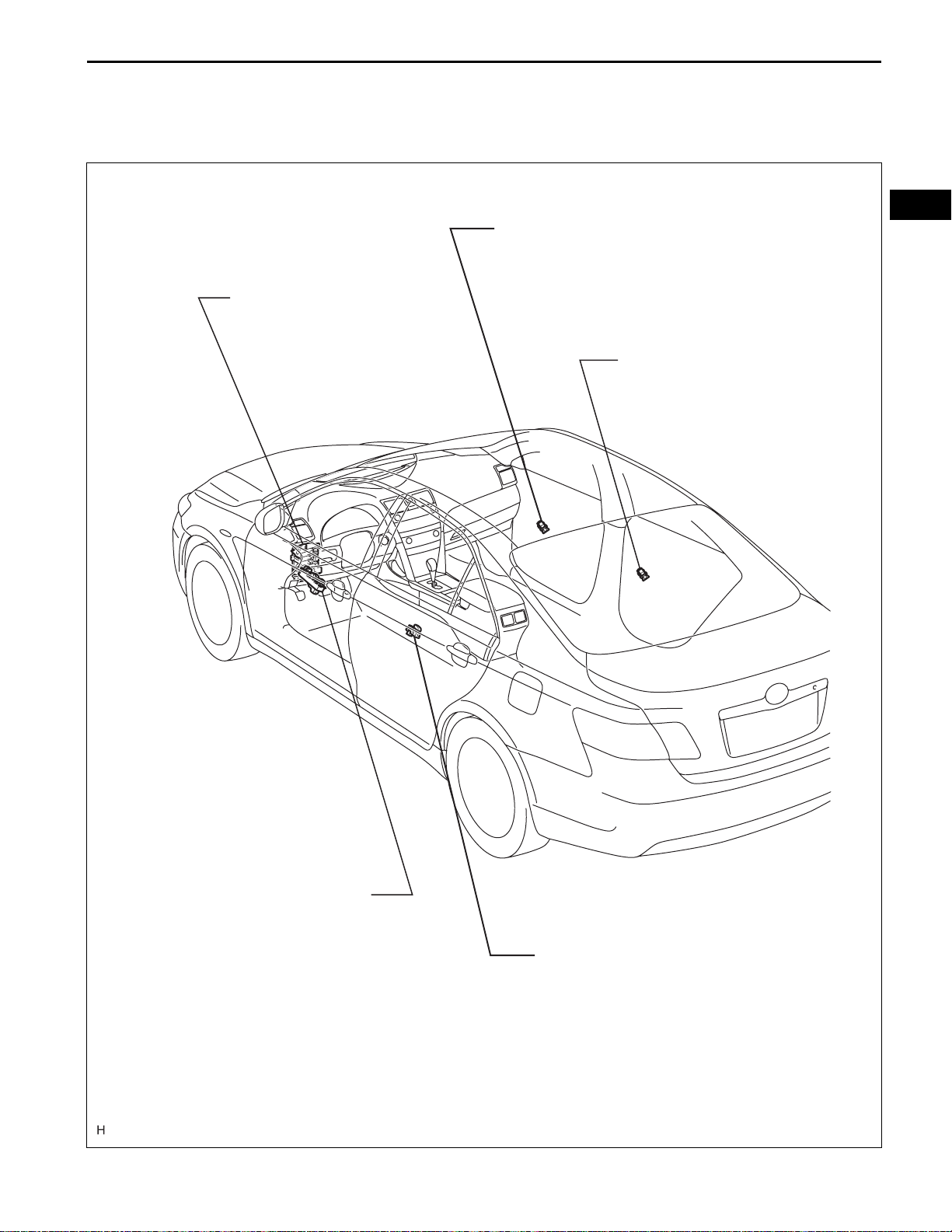
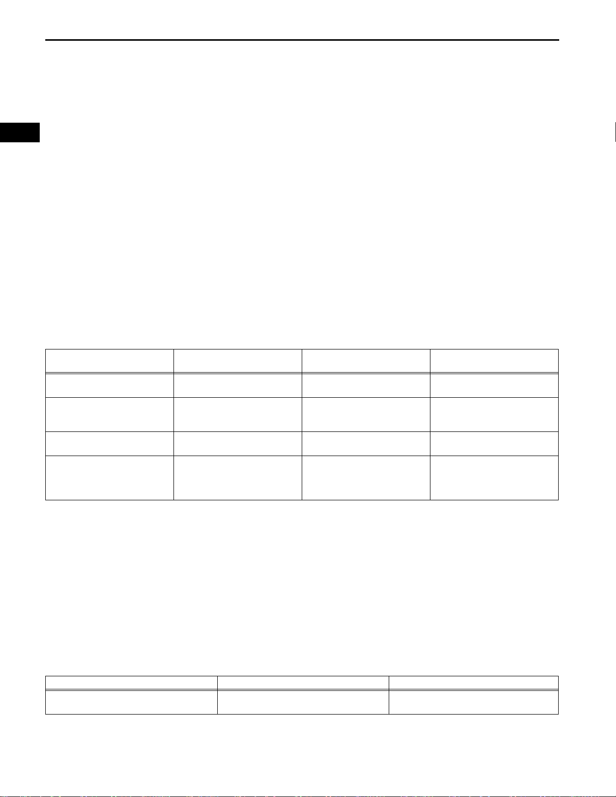
PARTS LOCATION
WS–1
MAIN BODY ECU
(INSTRUMENT PANEL J/B)
- POWER FUSE
- RR DOOR LH FUSE
- RR DOOR RH FUSE
POWER WINDOW REGULATOR
SWITCH ASSEMBLY (FRONT RH)
POWER WINDOW REGULATOR
SWITCH ASSEMBLY (REAR RH)
WS
POWER WINDOW REGULATOR
MASTER SWITCH ASSEMBLY
POWER WINDOW REGULATOR
SWITCH ASSEMBLY (REAR LH)
B137050E01
WS
WS–2
WINDSHIELD / WINDOWGLASS – POWER WINDOW CONTROL SYSTEM
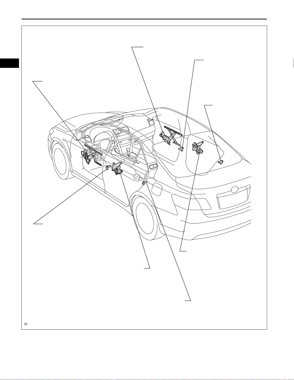
POWER WINDOW REGULATOR MOTOR
(FRONT RH)
DOOR COURTESY
SWITCH (FRONT RH)
POWER WINDOW REGULATOR
MOTOR
(FRONT LH)
DOOR COURTESY
SWITCH (REAR RH)
DOOR COURTESY
SWITCH (FRONT LH)
POWER WINDOW REGULATOR
MOTOR
(REAR LH)
POWER WINDOW REGULATOR
MOTOR
(REAR RH)
DOOR COURTESY
SWITCH (REAR LH)
B137082E01

WINDSHIELD / WINDOWGLASS – POWER WINDOW CONTROL SYSTEM
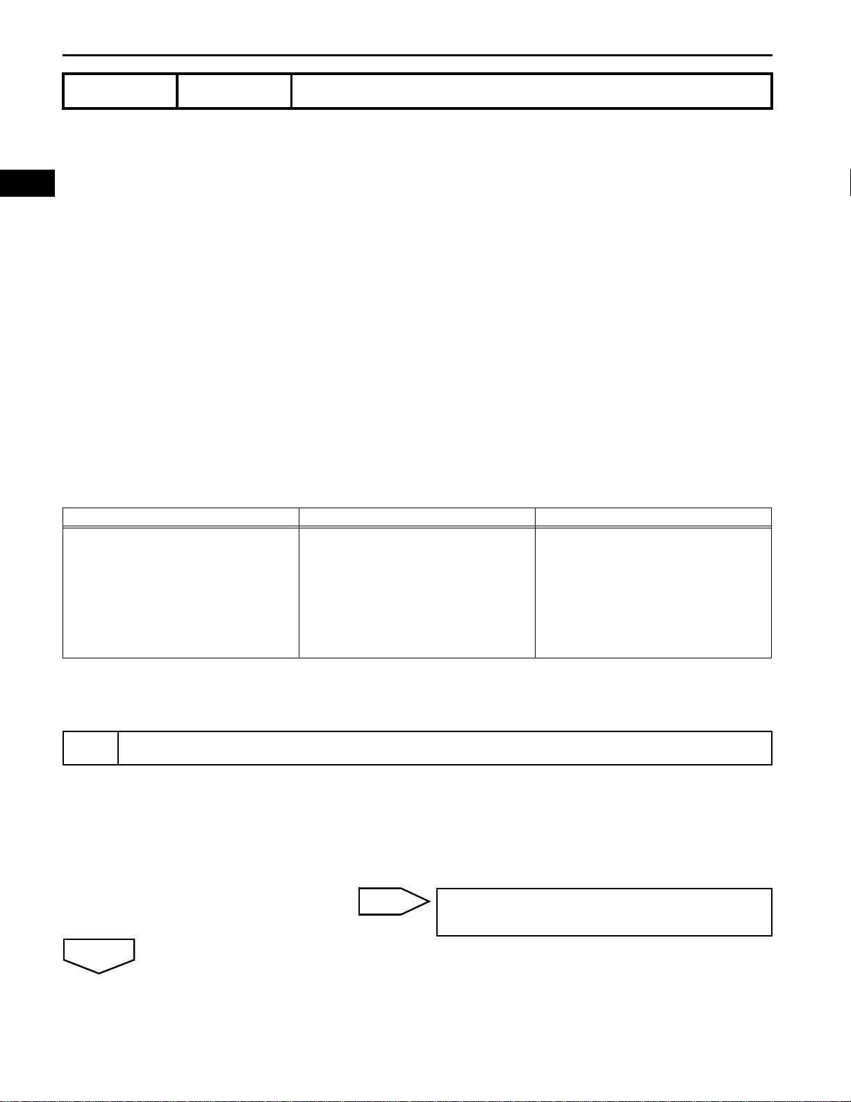
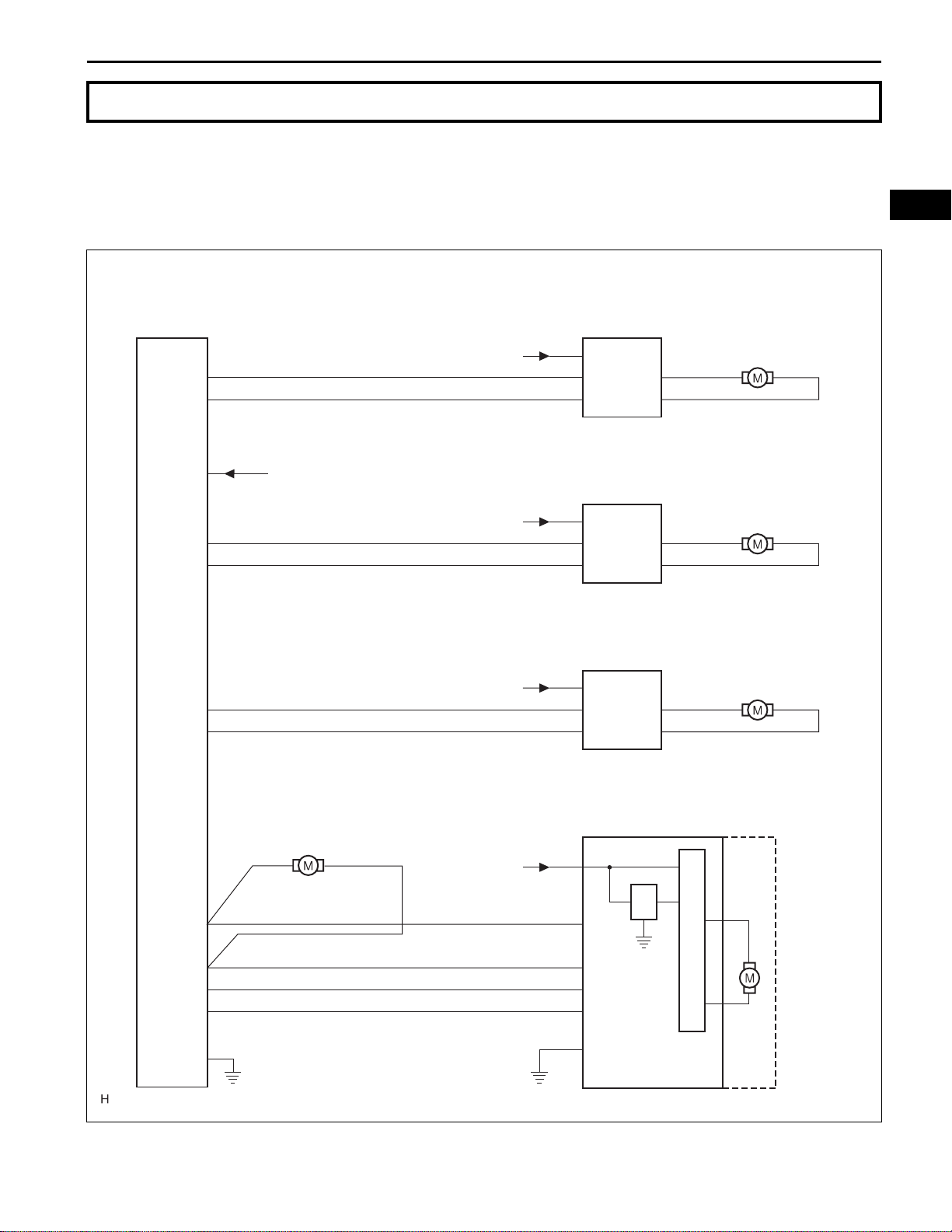
SYSTEM DIAGRAM
WS–3
Power Window Regulator
Master Switch Assembly
PU
PD
B
RRU
RRD
RLU
RLD
from POWER fuse
from RR DOOR RH fuse
from RR DOOR LH fuse
Power Window Regulator
Switch Assembly (Front RH)
from POWER fuse B
Power Window Regulator
Switch Assembly (Rear RH)
Power Window Regulator
Switch Assembly (Rear LH)
SU
SD
B
SU
SD
B
SU
SD
Power Window
Regulator Motor
WS
U
D
Power Window
Regulator Motor
U
D
Power Window
Regulator Motor
U
D
DN
UP
AUTO
E
LED
Main Body ECU
: LIN Communication Line
Power Window Regulator
Motor (Front LH)
from PWR fuse
(*1)
(*2)
(*1)
(*2)
(*2)
(*2)
*1: without Jam Protection
*2: with Jam Protection
(*2)
Power Window Regulator
Motor (Front LH)
B
(*2)
DWN1
UP1
AUTO
LED
LINLIN
E
(*2)
B137051E01

WS
WS–4
WINDSHIELD / WINDOWGLASS – POWER WINDOW CONTROL SYSTEM
SYSTEM DESCRIPTION
1. POWER WINDOW CONTROL SYSTEM
DESCRIPTION
(a) The power window control system controls the
power window operation using the power window
regulator motors. The main controls of this system
are the power window regulator master switch,
which is mounted on the driver side door, and the
power window regulator switches, which are
mounted on the passenger side door and rear
doors. Operating a window switch results in
electrical power being transmitted to the
corresponding power window regulator motor.
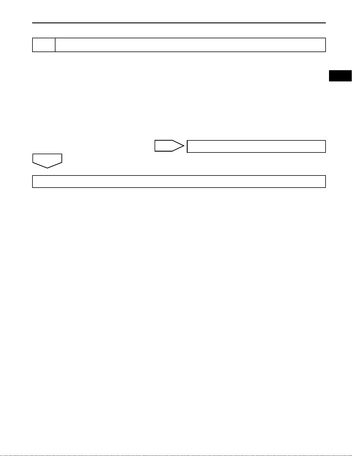
(b) The power window control system has the following
functions:
Function Outline
Function that causes window to go up while power window switch is
Manual up-and-down function
Driver's door auto up-and-down function *
Jam protection function
Remote control function
Key-off operation function
Key-linked up-and-down function
Diagnosis
Fail-safe
being pulled halfway up and to go down while pushed halfway down.
Window stops as soon as the switch is released.
Function that enables windows of driver's doors to be fully opened or
closed by one press of power window switch.
Function that automatically stops power window and moves it
downward if a foreign object gets jammed in door window during autoup operation.
Function that allows power window master switch to control MANUAL
up-and-down operations of front passenger door window and rear
door windows.
Function that makes it possible to operate power window for approx.
45 seconds after ignition switch is turned on (ACC) or off, if either front
door is not opened.
Function that causes window to go up while driver's door key is turned
to lock side for more than 1.5 seconds and to go down while turned to
unlock side for more than 1.5 seconds. Window stops as soon as the
key is returned to original position.
Function that allows the power window switch to make a diagnosis for
failed section when power window switch detects a malfunction in
power window system. Power window switch light comes on or blinks
to inform driver.
A fail-safe function to disable a part of power window functions if pulse
sensor in power window motor has a malfunction:
Driver's door auto up-and-down function and remote control function
are disabled.
*: with Jam Protection
1
NEXT
2
NEXT
3
WINDSHIELD / WINDOWGLASS – POWER WINDOW CONTROL SYSTEM
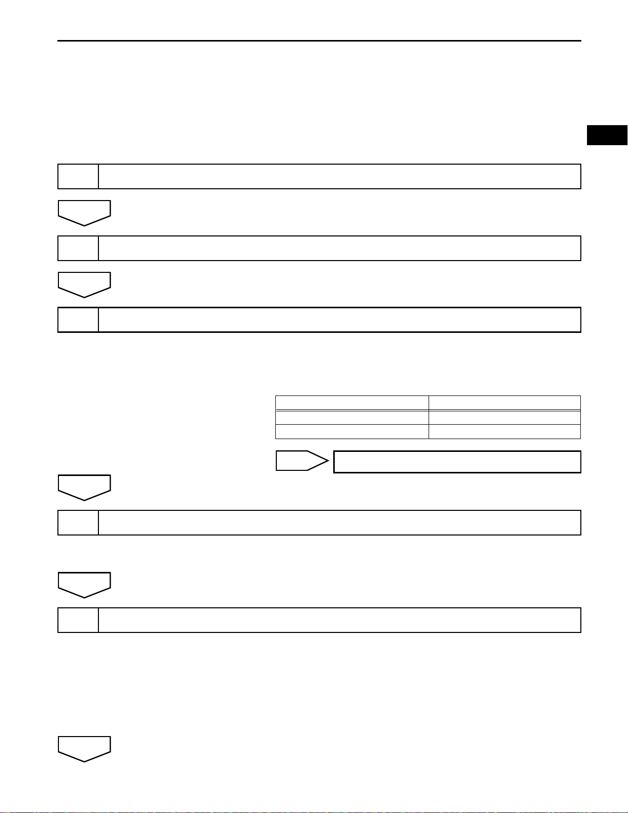
HOW TO PROCEED WITH
TROUBLESHOOTING
HINT:
• Use the following procedure to troubleshoot the power
window control system.
• The intelligent tester should be used in steps 3 and 5.
VEHICLE BROUGHT TO WORKSHOP
CUSTOMER PROBLEM ANALYSIS CHECK AND SYMPTOM CHECK
CHECK COMMUNICATION FUNCTION OF LIN COMMUNICATION SYSTEM
WS–5
WS
A
4
NEXT
5
(a) Use the intelligent tester , inspect the LIN communication
function to ensure there are no malfunctions in the
communication system.
Result
Result Proceed to
No DTCs output A
DTCs output B
B
PROBLEM SYMPTOMS TABLE
HINT:
See page WS-9.
OVERALL ANALYSIS AND TROUBLESHOOTING
GO TO DIAGNOSIS TROUBLE CODE CHART
NEXT
(a) Data list/Active test
HINT:
See page WS-17.
(b) Circuit inspection
(c) Terminal of ECU
HINT:
See page WS-9.
WS
WS–6
6
NEXT
7
NEXT
END
Standard
WINDSHIELD / WINDOWGLASS – POWER WINDOW CONTROL SYSTEM
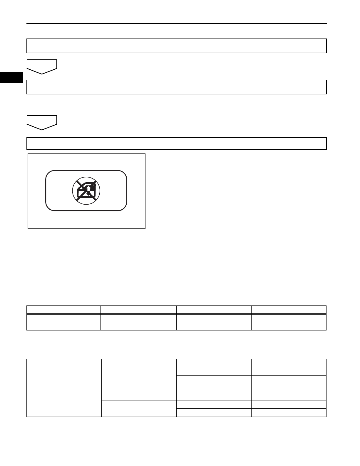
ADJUST, REPAIR OR REPLACE
RESET POWER WINDOW MOTOR
B140183
HINT:
See page WS-8.
OPERATION CHECK
1. CHECK WINDOW LOCK SWITCH
(a) Check that the front passenger side power window
and rear power windows operation are disabled
when the window lock switch of the power window
master switch is pressed.
Standard:
Front passenger side power window and rear
power windows operation are disabled.
(b) Check that the front passenger side power window
and rear power windows can be operated when the
window lock switch is pressed again.
Standard:
Front passenger side power window and rear
power windows can be operated.
2. CHECK MANUAL UP/DOWN FUNCTION
(a) Check that the driver side power window operates
as follows:
Condition Master Switch Switch Operation Power Window
Ignition switch on (IG) Driver side
Standard
Condition Switch Switch Operation Power Window
• Ignition switch on (IG)
• Window lock switch OFF
Passenger side
Rear LH
Rear RH
Pulled halfway up UP (Closed)
Pushed halfway down DOWN (Open)
(b) Check that the power windows except the driver
side power window operate as follows:
Pulled up UP (Closed)
Pushed down DOWN (Open)
Pulled up UP (Closed)
Pushed down DOWN (Open)
Pulled up UP (Closed)
Pushed down DOWN (Open)
WINDSHIELD / WINDOWGLASS – POWER WINDOW CONTROL SYSTEM
Standard
Condition Master Switch Switch Operation Power Window
Ignition switch on (IG) Driver side
Standard
Condition Master Switch Switch Operation Power Window
• Ignition switch on (IG)
• Window lock switch OFF
Passenger side
Rear LH
Rear RH
WS–7
3. CHECK AUTO UP/DOWN FUNCTION
(a) Check that the driver side power window operates
as follows:
Pulled up fully UP (Closed)
Pushed down fully DOWN (Open)
4. CHECK REMOTE MANUAL UP/DOWN FUNCTION
(a) Check that the power windows except the driver
side power window operate as follows:
Pulled up UP (Closed)
Pushed down DOWN (Open)
Pulled up UP (Closed)
Pushed down DOWN (Open)
Pulled up UP (Closed)
Pushed down DOWN (Open)
WS
Check Jig
B051853E05
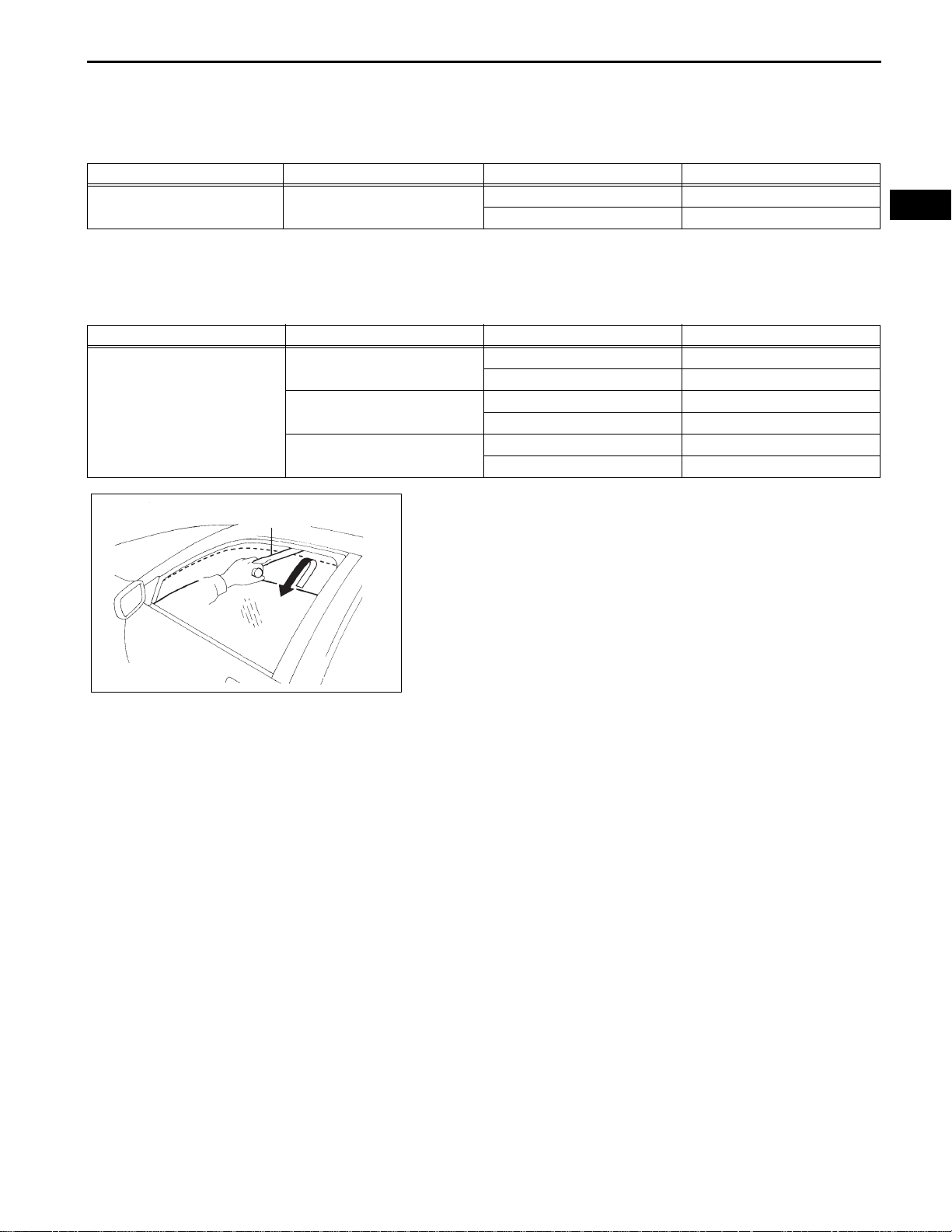
5. CHECK JAM PROTECTION FUNCTION
NOTICE:
• The jam protection function can activate when
either the AUTO UP function or MANUAL UP
function is used.
• Limbs, fingers or other body parts should not be
used to test the jam protection function. Do not
allow any body parts to get caught by the moving
window or regulator.
HINT:
The jam protection function can activate when either the
AUTO UP function or MANUAL UP function are used
with the ignition switch ON. The jam protection function
can also activate as long as the driver's door remains
closed, within 45 seconds after the ignition switch is
turned off.
(a) Check the reversing distance.
(1) Fully open the door glass.
(2) Place a check jig measuring 4 to 10 mm (0.16 to
0.40 in.) thick near the window fully closed
position.
(3) When the door glass is closed using AUTO or
MANUAL operation, check that the door glass
goes down after contacting the check jig. The
glass should go 200 to 240 mm (7.90 to 9.44 in.)
away from the position where it contacted the
check jig.
(4) While the door glass is going down, verify that
the window switch can not be used to make the
glass go up.
(b) Check the reversing distance.
(1) Fully open the door glass.

WS
WS–8
WINDSHIELD / WINDOWGLASS – POWER WINDOW CONTROL SYSTEM
(2) Place a check jig measuring 200 to 250 mm
(7.90 to 9.84 in.) thick near the window fully
closed position.
(3) When the door glass is closed using AUTO or
MANUAL operation, check that the door glass
goes down after contacting the check jig. The
door glass should go 80 to 100 mm away from
the position where it contacted the check jig.
(4) While the door glass is going down, verify that
the window switch can not be used to make the
glass go up.

WINDSHIELD / WINDOWGLASS – POWER WINDOW CONTROL SYSTEM
INITIALIZATION
1. INITIALIZE POWER WINDOW REGULATOR MOTOR
FRONT LH (WITH JAM PROTECTION)
NOTICE:
• If the power window motor or power window
regulator assembly is replaced, initialization is
required (initialization is not necessary when the
negative battery terminal is disconnected and
reconnected).
• No other electrical systems should be operated
during initialization. Initialization will be
interrupted if a voltage drop occurs in the power
being supplied to the power window motor.
• Replacing the door glass or door glass run may
cause a difference to exist between the current
door glass position and the position memorized
in the ECU. In this case, the jam protection
function may work improperly. Return the system
to the pre-initialized condition and reinitialize the
system.
HINT:
• The AUTO UP function will not work unless
initialization is completed.
• The indicator on the power window master switch will
blink when the ignition switch is ON, until initialization
has been completed. The indicator will remain on
after initialization is successfully completed.
(a) Connect the negative battery terminal.
(b) Turn the ignition switch on (IG). The ind icator on the
power window master switch will blink.
(c) Fully close the door glass by operating the power
window master switch. After the door glass stops,
hold the power window master switch in the AUTO
UP position for 1 second or more.
(d) Check that the indicator on the power window
master switch remains on.
HINT:
If the indicator does not remain on, this means that
initialization has not been completed successfully . In
this case, lower the door glass at least 50 mm (1.96
in.) and hold the power window master switch in the
AUTO UP position for 1 second after the window
closes fully.
2. TO RETURN THE SYSTEM TO THE PRE-INITIALIZES
CONDITION
Disconnect the power window regulator motor connector
during power window operation. This will return the
motor to the pre-initialized condition.
WS–9
WS
WS
WS–10
WINDSHIELD / WINDOWGLASS – POWER WINDOW CONTROL SYSTEM
POWER WINDOW CONTROL SYSTEM
Symptom Suspected area See page
Power window does not operate with power window
regulator master switch
Front passenger side power window does not operate
with power window regulator switch
Rear LH side power window does not operate with
power window regulator switch
Rear RH side power window does not operate with
power window regulator switch
AUTO UP/DOWN function does not operate on driver
side (Only jam protection assistant)
Remote UP/DOWN function does not operate
Power window can be operated after ignition switch is
turned off even if operated conditions are not met
AUTO UP operation does not fully close power window
(Jam protection function is activated)
AUTO DOWN function does not operate on driver side
(only DOWN AUTO)
PROBLEM SYMPTOMS TABLE
1. PWR, POWER, RR DOOR LH/RH fuses -
2. Power window master switch circuit (power source) WS-26
3. Power window regulator motor circuit WS-33
4. Power window regulator master switch -
1. Power window master switch circuit (power source) -
2. Power window regulator motor circuit (front passenger side) WS-36
3. Power window regulator switch (front LH side) WS-30
1. Power window regulator switch circuit (power source) -
2. Power window regulator motor circuit (rear LH side) WS-38
3. Power window regulator switch (rear LH side) WS-31
1. Power window regulator switch circuit (power source) -
2. Power window regulator motor circuit (rear RH side) WS-40
3. Power window regulator switch (rear RH side) WS-32
1. Diagnosis check WS-14
2. Power window regulator motor reset WS-8
3. Power window regulator master switch -
4. Wire harness -
1. DATA LIST/ACTIVE TEST WS-17
2. Power window regulator master switch -
3. Wire harness -
1. Front door courtesy switch LI-109
2. Wire harness (LIN communication line) -
1. Power window regulator motor reset WS-8
2. Check & clean glass run -
3. Power window regulator master switch -
1. Power window regulator master switch -
2. Power window regulator motor circuit (driver side) WS-33
3. Wire harness -
WINDSHIELD / WINDOWGLASS – POWER WINDOW CONTROL SYSTEM
WS–11
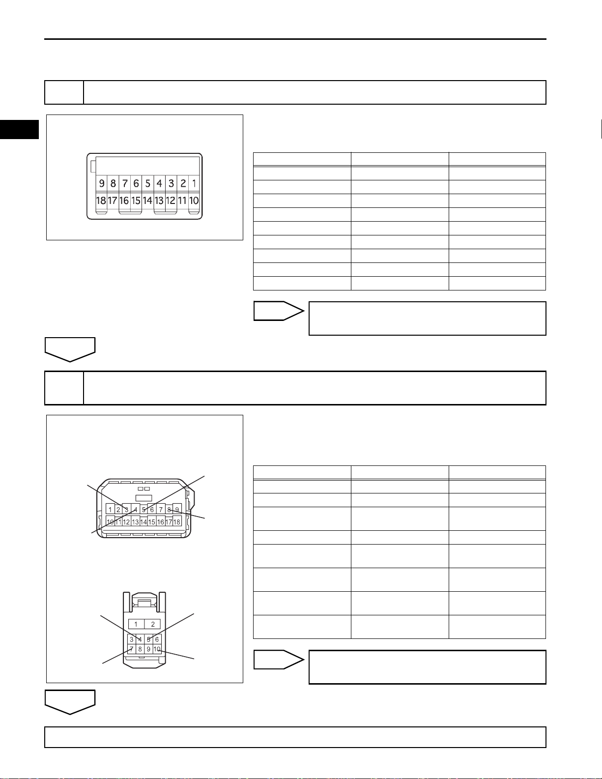
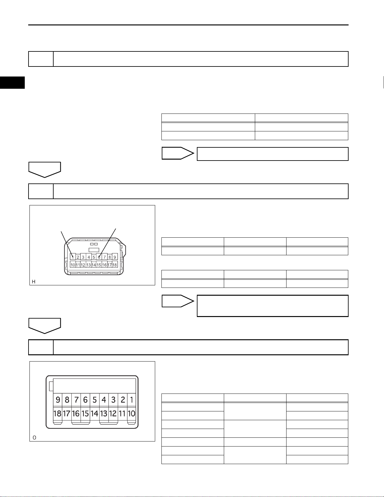
TERMINALS OF ECU
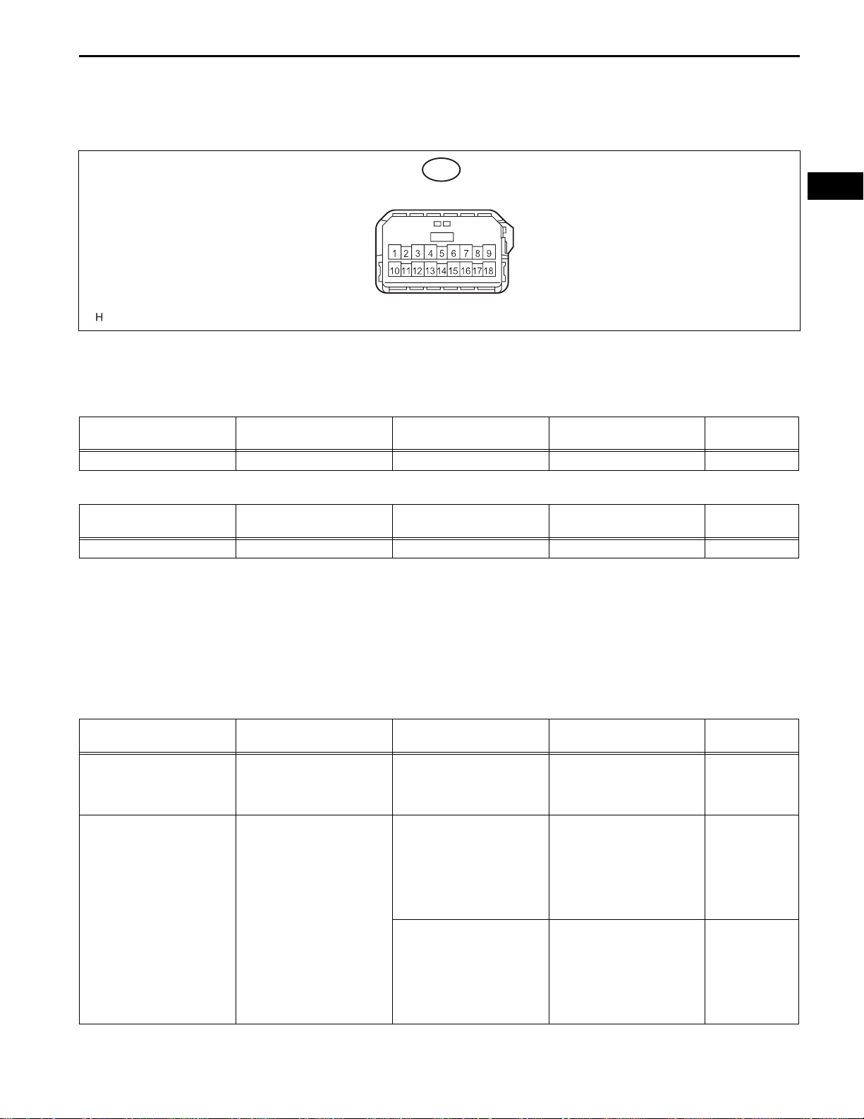
1. POWER WINDOW REGULATOR MASTER SWITCH
ASSEMBLY
M1
B137056E01
(a) Disconnect the M1 switch connector.
(b) Measure the voltage and resistance of each
terminal according to the value(s) in the table below.
Standard resistance
Symbols (Terminal No.) Wiring Color Terminal Description Condition
E (M1-1) - Body ground W-B - Body ground Ground Always Below 1 Ω
Specified
Condition
WS
Standard voltage
Symbols (Terminal No.) Wiring Color Terminal Description Condition
B (M1-6) - E (M1-1) GR - W-B Power supply Ignition switch on (IG) 10 to 14 V
Specified
Condition
If the result is not as specified, there may be a
malfunction in the wire harness.
(c) Reconnect the M1 switch connector and reset the
power window motor.
(d) Measure the voltage according to the value(s) in the
table below.
Standard voltage:
with Jam protection
Symbols (Terminal No.) Wiring Color Terminal Description Condition
Ignition switch on (IG),
UP (M1-8) - E (M1-1) G - W-B
AUTO (M1-4) - E (M1-1) B - W-B
Power window motor UP
output
Power window motor
AUTO UP output
Power window motor
AUTO DOWN output
driver side power window
switch OFF → UP (Manual
operation)
Ignition switch on (IG),
driver side power window
fully open → driver side
power window switch UP
(AUTO UP position) →
driver side power window
fully closed
Ignition switch on (IG),
driver side power window
fully closed → driver side
power window switch
DOWN (AUTO UP position)
→ driver side power
window fully open
Specified
Condition
10 to 14 V → 0
V
10 to 14 V → 0
V → 10 to 14 V
10 to 14 V → 0
V → 10 to 14 V

WS–12
WINDSHIELD / WINDOWGLASS – POWER WINDOW CONTROL SYSTEM
WS
Symbols (Terminal No.) Wiring Color Terminal Description Condition
Ignition switch on (IG),
DN (M1-5) - E (M1-1) R - W-B
PU (M1-16) - E (M1-1) W - W-B
PD (M1-15) - E (M1-1) R - W-B
RLU (M1-12) - E (M1-1) L - W-B
RLD (M1-13) - E (M1-1) B - W-B
RRU (M1-10) - E (M1-1) Y - W-B
RRD (M1-18) - E (M1-1) LG - W-B
Power window motor
DOWN output
Power window motor UP
output
Power window motor
DOWN output
Power window motor UP
output
Power window motor
DOWN output
Power window motor UP
output
Power window motor
DOWN output
driver side power window
switch OFF → DOWN
(Manual operation)
Ignition switch on (IG),
front passenger side
power window switch OFF
→ UP (Manual operation)
Ignition switch on (IG),
front passenger side
power window switch OFF
→ DOWN (Manual
operation)
Ignition switch on (IG), rear
LH side power window
switch OFF → UP (Manual
operation)
Ignition switch on (IG), rear
LH side power window
switch OFF → UP (Manual
operation)
Ignition switch on (IG), rear
RH side power window
switch OFF → UP (Manual
operation)
Ignition switch on (IG), rear
RH side power window
switch OFF → UP (Manual
operation)
Specified
Condition
10 to 14 V → 0
V
0 V → 10 to 14
V
0 V → 10 to 14
V
0 V → 10 to 14
V
0 V → 10 to 14
V
0 V → 10 to 14
V
0 V → 10 to 14
V
without Jam protection
Symbols (Terminal No.) Wiring Color Terminal Description Condition
Ignition switch on (IG),
UP (M1-3) - E (M1-1) G - W-B
DN (M1-4) - E (M1-1) G - W-B
PU (M1-16) - E (M1-1) W - W-B
PD (M1-15) - E (M1-1) R - W-B
RLU (M1-12) - E (M1-1) L - W-B
Power window motor UP
output
Power window motor
DOWN output
Power window motor
AUTO DOWN output
Power window motor UP
output
Power window motor
DOWN output
Power window motor UP
output
driver side power window
switch OFF → UP (Manual
operation)
Ignition switch on (IG),
driver side power window
switch OFF → DOWN
(Manual operation)
Ignition switch on (IG),
driver side power window
fully closed → driver side
power window switch
DOWN (AUTO operation)
→ driver side power
window fully open
Ignition switch on (IG),
front passenger side
power window switch OFF
→ UP (Manual operation)
Ignition switch on (IG),
front passenger side
power window switch OFF
→ DOWN (Manual
operation)
Ignition switch on (IG), rear
LH side power window
switch OFF → UP (Manual
operation)
Specified
Condition
0 V → 10 to 14
V
0 V → 10 to 14
V
10 to 14 V → 0
V → 10 to 14 V
0 V → 10 to 14
V
0 V → 10 to 14
V
0 V → 10 to 14
V
WINDSHIELD / WINDOWGLASS – POWER WINDOW CONTROL SYSTEM
WS–13
Symbols (Terminal No.) Wiring Color Terminal Description Condition
Ignition switch on (IG), rear
RLD (M1-13) - E (M1-1) B - W-B
RRU (M1-10) - E (M1-1) Y - W-B
RRD (M1-18) - E (M1-1) LG - W-B
Power window motor
DOWN output
Power window motor UP
output
Power window motor
DOWN output
LH side power window
switch OFF → DOWN
(Manual operation)
Ignition switch on (IG), rear
RH side power window
switch OFF → UP (Manual
operation)
Ignition switch on (IG), rear
RH side power window
switch OFF → DOWN
(Manual operation)
If the result is not as specified, there may be a
malfunction in the wire harness.
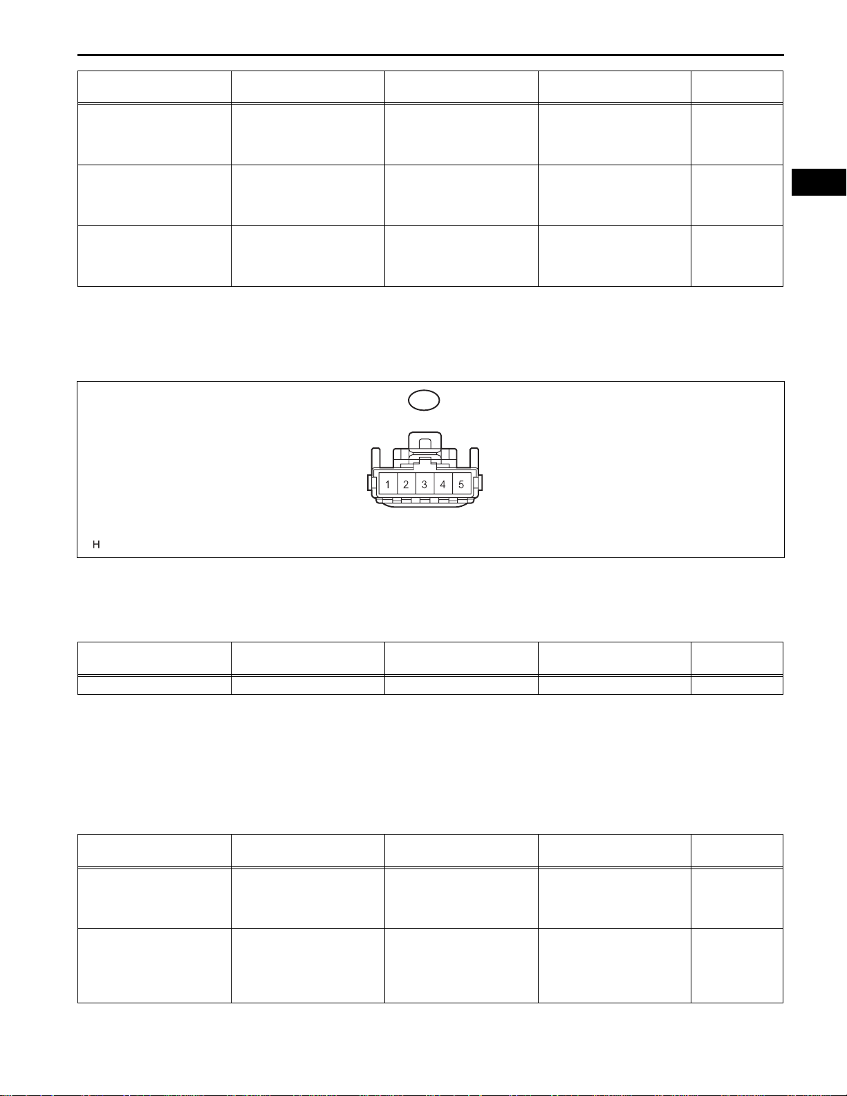
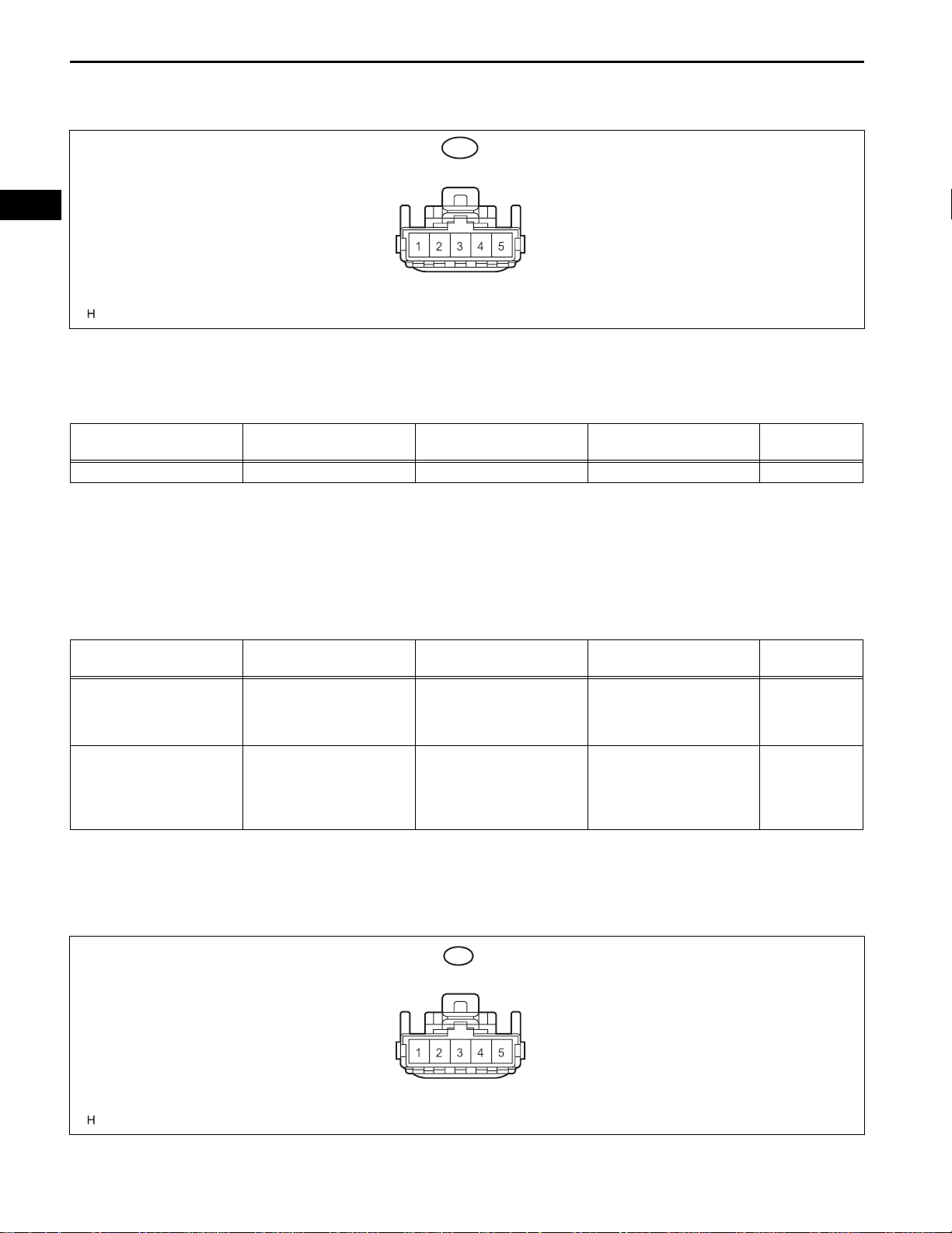
2. CHECK POWER WINDOW REGULATOR SWITCH
ASSEMBLY (FRONT RH)
H6
Specified
Condition
0 V → 10 to 14
V
0 V → 10 to 14
V
0 V → 10 to 14
V
WS
B137057E01
(a) Disconnect the H6 switch connector.
(b) Measure the voltage according to the value(s) in the
table below.
Standard voltage
Symbols (Terminal No.) Wiring Color Terminal Description Condition
B (H6-3) - Body ground GR - Body ground Power supply Ignition switch on (IG) 10 to 14 V
Specified
Condition
If the result is not as specified, there may be a
malfunction in the wire harness.
(c) Reconnect the H6 switch connector and reset the
power window motor.
(d) Measure the voltage according to the value(s) in the
table below.
Standard voltage
Symbols (Terminal No.) Wiring Color Terminal Description Condition
Ignition switch on (IG),
U (H6-4) - Body ground G - Body ground
D (H6-1) - Body ground Y - Body ground
Power window motor UP
output
Power window motor
DOWN output
front passenger side
power window switch OFF
→ UP (Manual operation)
Ignition switch on (IG),
front passenger side
power window switch OFF
→ DOWN (Manual
operation)
Specified
Condition
0 V → 10 to 14
V
0 V → 10 to 14
V
If the result is not as specified, the power window
regulator switch assembly may have a malfunction.
WS
WS–14
WINDSHIELD / WINDOWGLASS – POWER WINDOW CONTROL SYSTEM
3. CHECK POWER WINDOW REGULATOR SWITCH
ASSEMBLY (REAR LH)
K1
B137057E02
(a) Disconnect the K1 switch connector.
(b) Measure the voltage according to the va lue(s) in the
table below.
Standard voltage
Symbols (Terminal No.) Wiring Color Terminal Description Condition
B (K1-3) - Body ground V - Body ground Power supply Ignition switch on (IG) 10 to 14 V
Specified
Condition
If the result is not as specified, there may be a
malfunction in the wire harness.
(c) Reconnect the K1 switch connector and reset the
power window motor.
(d) Measure the voltage according to the va lue(s) in the
table below.
Standard voltage
Symbols (Terminal No.) Wiring Color Terminal Description Condition
Ignition switch on (IG),
U (K1-4) - Body ground G - Body ground
D (K1-1) - Body ground R - Body ground
Power window motor UP
output
Power window motor
DOWN output
front passenger side
power window switch OFF
→ UP (Manual operation)
Ignition switch on (IG),
front passenger side
power window switch OFF
→ DOWN (Manual
operation)
If the result is not as specified, the power window
regulator switch assembly may have a malfunction.
4. CHECK POWER WINDOW REGULATOR SWITCH
ASSEMBLY (REAR RH)
Specified
Condition
0 V → 10 to 14
V
0 V → 10 to 14
V
J1
(a) Disconnect the J1 switch connector.
B137057E03

WINDSHIELD / WINDOWGLASS – POWER WINDOW CONTROL SYSTEM
WS–15
(b) Measure the voltage according to the value(s) in the
table below.
Standard voltage
Symbols (Terminal No.) Wiring Color Terminal Description Condition
B (J1-3) - Body ground G - Body ground Power supply Ignition switch on (IG) 10 to 14 V
Specified
Condition
If the result is not as specified, there may be a
malfunction in the wire harness.
(c) Reconnect the J1 switch connector and reset the
power window motor.
(d) Measure the voltage according to the value(s) in the
table below.
Standard voltage
WS
Symbols (Terminal No.) Wiring Color Terminal Description Condition
Ignition switch on (IG),
U (J1-4) - Body ground V - Body ground
D (J1-1) - Body ground R - Body ground
Power window motor UP
output
Power window motor
DOWN output
front passenger side
power window switch OFF
→ UP (Manual operation)
Ignition switch on (IG),
front passenger side
power window switch OFF
→ DOWN (Manual
operation)
If the result is not as specified, the power window
regulator switch assembly may have a malfunction.
Specified
Condition
0 V → 10 to 14
V
0 V → 10 to 14
V
WS
WS–16
WINDSHIELD / WINDOWGLASS – POWER WINDOW CONTROL SYSTEM
DIAGNOSIS SYSTEM
1. DESCRIPTION
(a) The power window control system data can be read
from the Data Link Connector 3 (DLC3) of the
vehicle. When the system seems to be
malfunctioning, use the intelligent tester to check for
malfunctions and perform repairs.
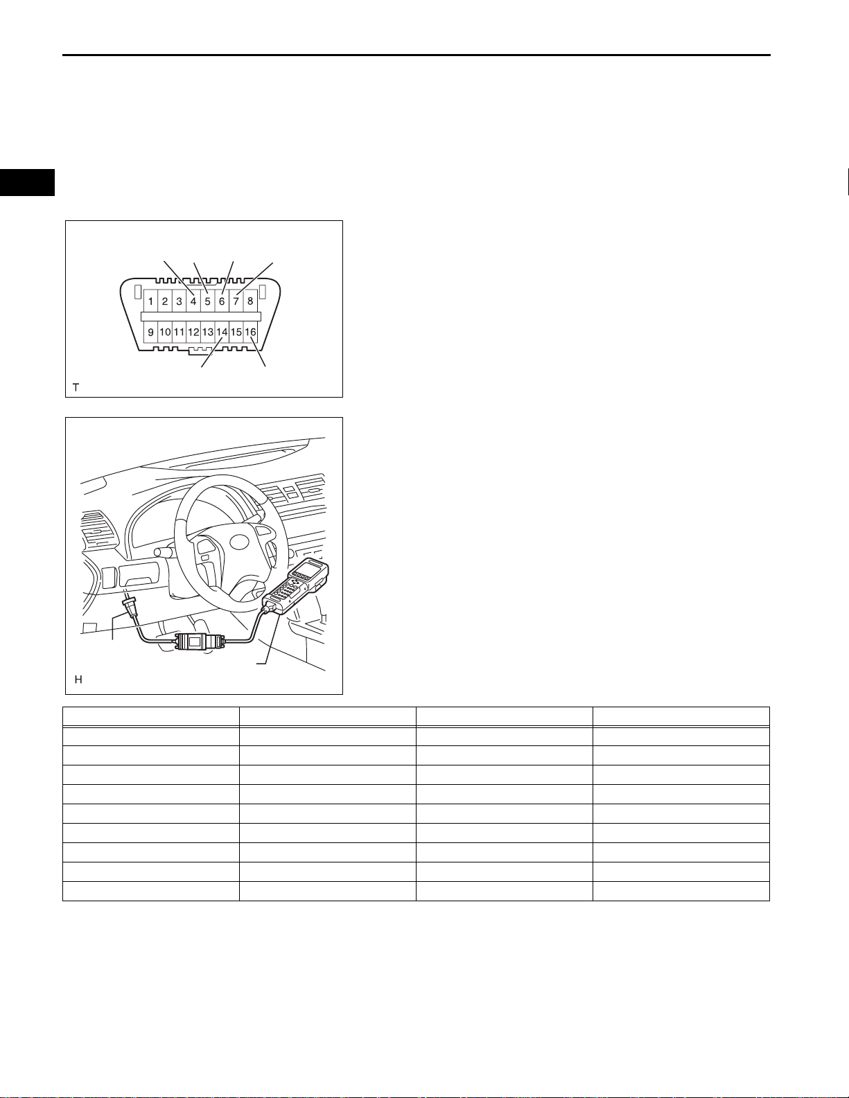
2. CHECK DLC3
CG
SG
CANH
SIL
CANL
BAT
H100769E16
(a) The ECU uses ISO 15765-4 communication. The
terminal arrangement of the DLC3 complies with
SAE J1962 and matches the ISO 15765-4 format.
DLC3
Intelligent Tester
C131977E01
Symbols (Terminal No.) Terminal Description Condition Specified Condition
SIL (7) - SG (5) Bus "+" line During transmission Pulse generation
CG (4) - Body ground Chassis ground Always Below 1 Ω
SG (5) - Body ground Signal ground Always Below 1 Ω
BAT (16) - Body ground Battery positive Always 10 to 14 V
CANH (6) - CANL (14) CAN bus line Ignition switch OFF* 54 to 69 Ω
CANH (6) - CG (4) HIGH-level CAN bus line Ignition switch OFF* 200 Ω or more
CANL (14) - CG (4) LOW-level CAN bus line Ignition switch OFF* 200 Ω or more
CANH (6) - BAT (16) HIGH-level CAN bus line Ignition switch OFF* 6 kΩ or more
CANL (14) - BAT (16) LOW-level CAN bus line Ignition switch OFF* 6 kΩ or more
NOTICE:
*: Before measuring the resistance, leave the
vehicle as is for at least 1 minute and do not
operate the ignition switch, any other switches
or the door.

WINDSHIELD / WINDOWGLASS – POWER WINDOW CONTROL SYSTEM
If the result is not as specified, the DLC3 may have
a malfunction. Repair or replace the harness and
connector.
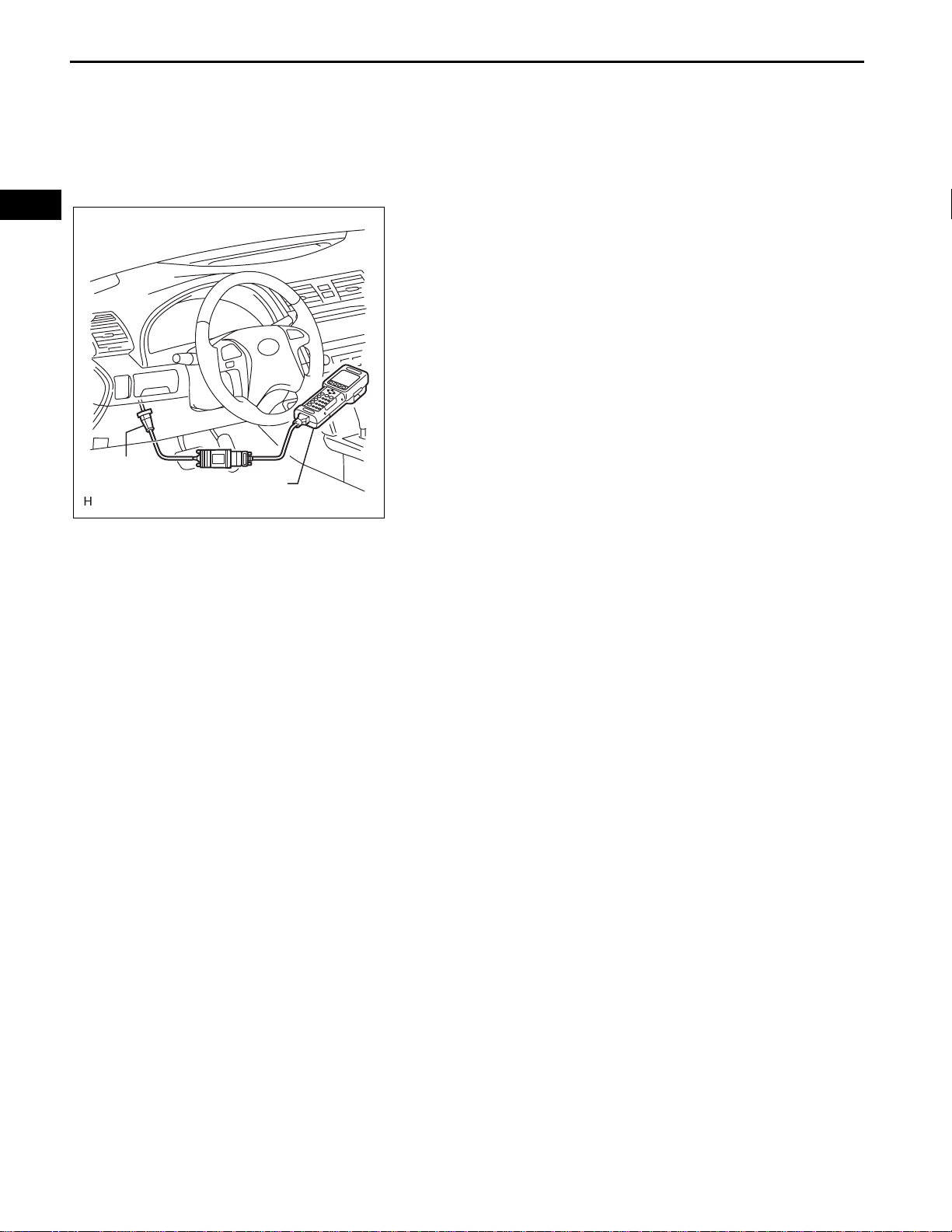
HINT:
Connect the cable of the intelligent tester to the
DLC3, turn the ignition switch on (IG) and attempt to
use the tester. If the display indicates that a
communication error has occurred, there is a
problem either with the vehicle or with the tester.
• If communication is normal when the tester is
connected to another vehicle, inspect the DLC3
of the original vehicle.
• If communication is still not possible when the
tester is connected to another vehicle, the
problem may be in the tester itself. Consult the
Service Department listed in the tester's
instruction manual.
3. CHECK DIAGNOSIS (WITH JAM PROTECTION)
HINT:
If there is a malfunction in the pulse sensor, manually
operating the power window switch will cause the power
window switch light to blink.
(a) Turn the ignition switch on (IG).
(b) Manually operate the power window master switch
or power window switch on each door.
(c) Check the blinking pattern of the AUTO light as
B140750
shown in the illustration.
WS–17
WS
Brinking Pattern of Light:
(A): LIN communication fail
ON
OFF
1.5
(Light)
2.0
(sec.)
- Initial fail (Window position)
Normal(B):
- Palse sensor fail
0.5
1.0
(sec.)
(1) If pattern (A) is displayed, check the wire
harness or power window ECU.
(2) If pattern (B) is displayed, check the power
window regulator motor or power window ECU.
(3) If the normal pattern is displayed, replace the
power window regulator master switch.
B145472E01
WS–18
WINDSHIELD / WINDOWGLASS – POWER WINDOW CONTROL SYSTEM
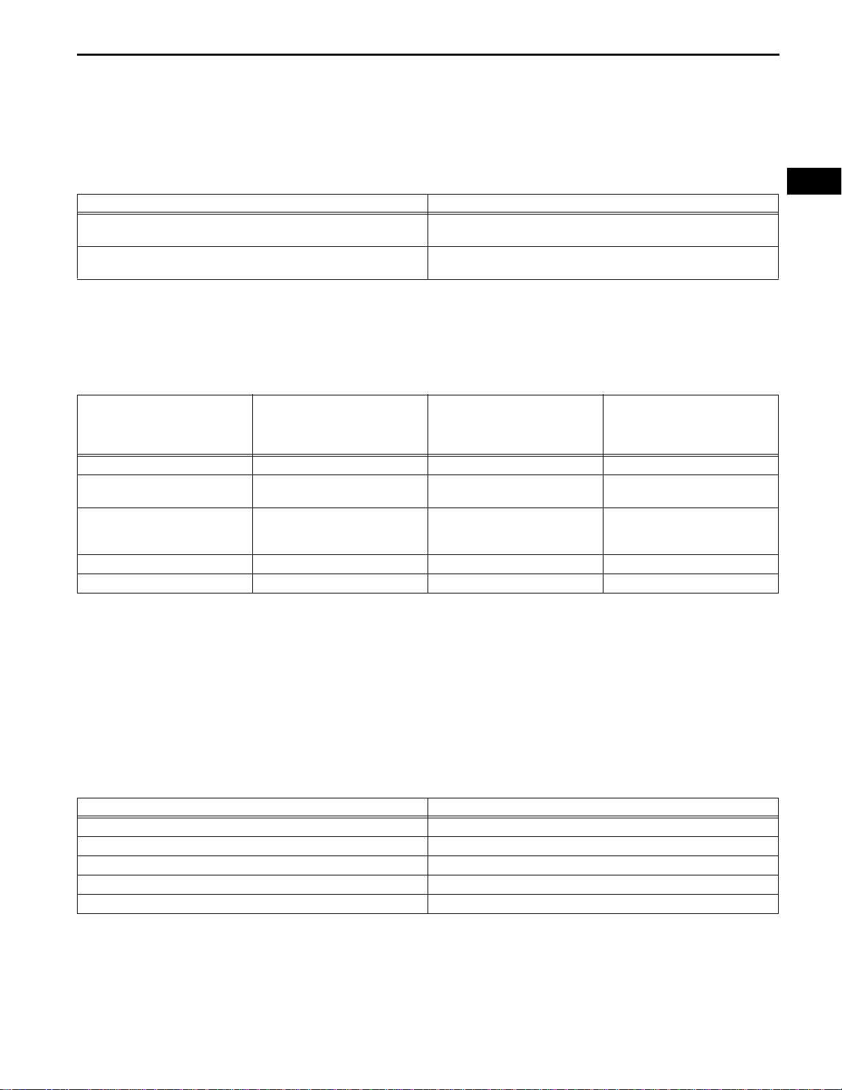
DTC CHECK / CLEAR
1. CHECK DTC
(a) Connect the intelligent tester to the DLC3.
(b) Turn the ignition switch on (IG).
(c) Check the DTC(s).
WS
2. CLEAR DTC
(a) Connect the intelligent tester to the DLC3.
(b) Turn the ignition switch on (IG) .
(c) Clear the DTCs.
(d) Check that "DTCs are cleared" is displayed.
NOTICE:
If any DTCs are output, troubleshoot those
DTCs again.
DLC3
Intelligent Tester
C131977E01
WINDSHIELD / WINDOWGLASS – POWER WINDOW CONTROL SYSTEM
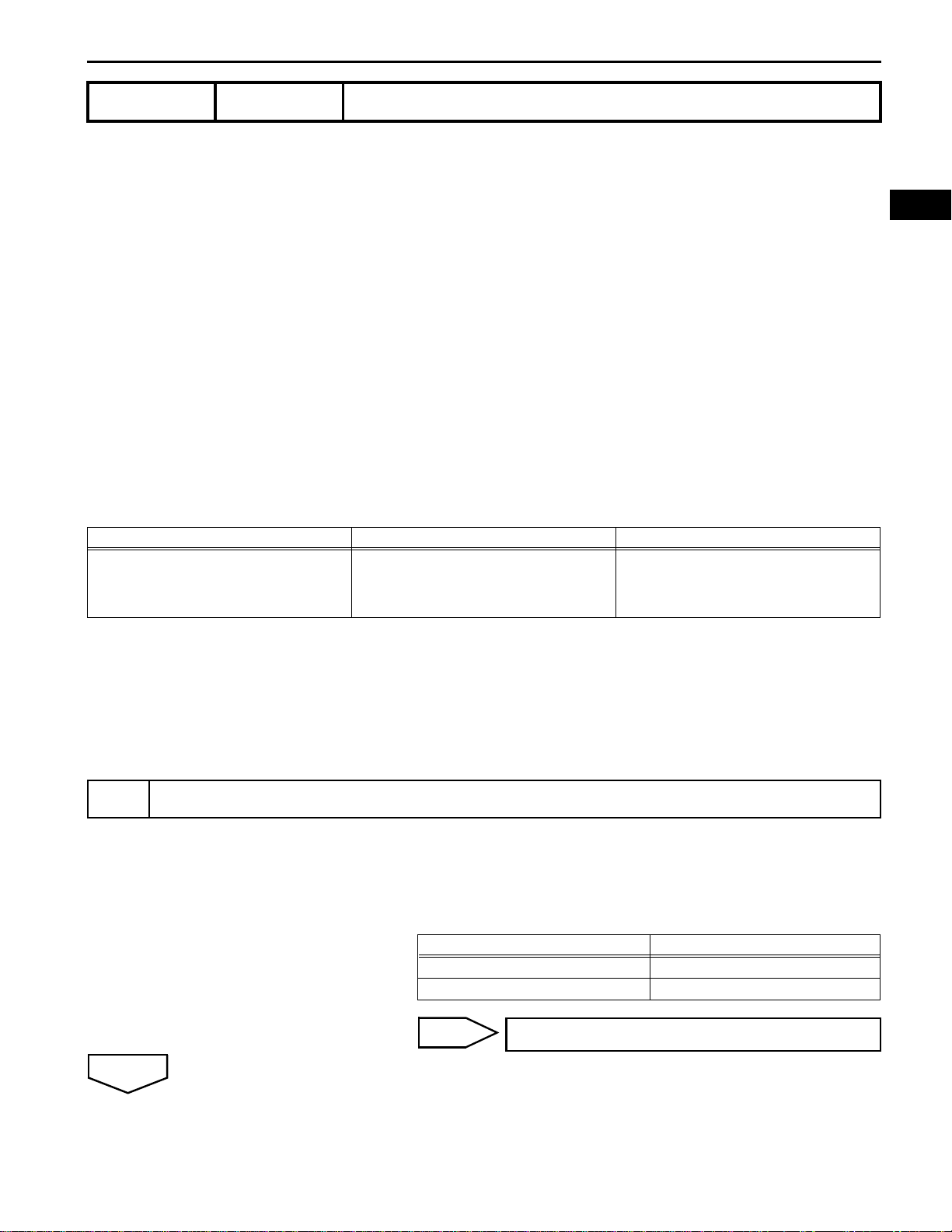
FAIL-SAFE CHART
1. POWER WINDOW OPERATION IN FAIL-SAFE MODE
HINT:
If the pulse sensor built into the power window regulator
motor (on the driver side) malfunctions, the power
window control system enters fail-safe mode.
Fail mode Fail Detection Condition
Pulse direction error
Pulse stop error
Power window control system
Power window operation Ignition switch on (IG)
Manual UP Operation prohibited Operation prohibited Operation prohibited
Manual DOWN
AUTO UP
(hold switch at AUTO UP
position)
AUTO UP Operation prohibited Operation prohibited Operation prohibited
AUTO DOWN Operation prohibited Operation prohibited Operation prohibited
Operative
(Jam protection not operative)
Operative
(in MANUAL mode)
(Jam protection not operative)
With the door glass going up or down, the pulse that indicates door
glass operation in the opposite direction is detected for 400 msec.
With the door glass going up or down, no pulse is detected for 350 to
450 msec.
(a) The power window control system prohibits the
following power window operation when the pulse
sensor for the jam protection function has problems
and the window position or the learned value is
abnormal.
Key-off
(Within approx. 45 seconds
after ignition switch turned off)
Operation prohibited Operation prohibited
Operation prohibited Operation prohibited
Key-off
(After approx. 45 seconds
elapsed after ignition switch
turned off)
WS–19
WS
HINT:
When the pulse sensor is normal, the AUTO UP /
DOWN function can be resumed by deactivating
fail-safe mode. To deactivate fail-safe mode, pull up
the driver door power window switch to the AUTO
UP position and hold it for at least 1 second to fully
close the window from the fully open position.
(b) If the LIN communication system malfunctions
(communication blackout), the power window
control system prohibits the following operations.
LIN communication system
Power window operation Ignition switch on (IG)
MANUAL UP Operative (Jam protection operative)
MANUAL DOWN Operative (Jam protection not operative)
AUTO UP (hold switch at AUTO UP position) Operative (Jam protection operative)
AUTO UP Operative (Jam protection operative)
AUTO DOWN Operative (Jam protection not operative)
WS
WS–20
WINDSHIELD / WINDOWGLASS – POWER WINDOW CONTROL SYSTEM
DATA LIST / ACTIVE TEST
1. USING INTELLIGENT TESTER
2. DATA LIST
Body:
Item
Communication Master SW
Ignition Switch Ignition switch signal/ON or OFF
D Door Courtesy SW
P Door Courtesy SW
Measurement Item/Display
(Range)
Master switch communication
signal OK/STOP
Driver side door courtesy switch
signal/ON or OFF
Front passenger side door
courtesy switch signal/ON or OFF
(a) Connect the intelligent tester to the DLC3.
(b) Monitor the ECU data by following the prompts on
the tester screen.
HINT:
The intelligent tester has a "Snapshot" function
which records the monitored data. Refer to the
intelligent tester operator's manual for further
details.
HINT:
Using the DATA LIST displayed on the intelligent tester,
the value of the switches, sensors, actuators, etc. can be
read without part removal. Reading the DATA LIST as
the first step in troubleshooting is one way to shorten the
labor time.
(a) Connect the intelligent tester to the DLC3.
(b) Turn the ignition switch on (IG).
(c) Read the DAT A LIST according to the display on the
tester.
Normal Condition
OK: Communication is normal
STOP: Communication is stop
ON: Power source mode is (IG)
OFF: Power source mode is off or
on (ACC)
ON: Driver side door is open
OFF: Driver side door is closed
ON: Front passenger side door is
open
OFF: Front passenger side door
is closed
Diagnostic Note
-
-
-
-
Body:
Item Test Detail Diagnostic Note
IG OFF P/W Control Permission Output
3. ACTIVE TEST
HINT:
Performing the ACTIVE TEST using the intelligent tester
allows you to operate the relay, VSV, actuator, etc.
without parts removal. Performing the ACTIVE TEST as
the first step in troubleshooting is one way to shorten the
labor time. It is possible to display the DATA LIST during
the ACTIVE TEST.
(a) Connect the intelligent tester to the DLC3.
(b) Turn the ignition switch on (IG).
(c) Perform the ACTIVE TEST according to the display
on the tester.
Operates power window ON/OFF (After
ignition OFF)
-

WINDSHIELD / WINDOWGLASS – POWER WINDOW CONTROL SYSTEM
POWER WINDOW CONTROL SYSTEM
DTC No. Detection Item Trouble Area See page
B2311 Driver Door Motor Malfunction
B2312
B2313
Driver Side Door Master Switch
Malfunction
Glass Position Initialization
Incomplete
WS–21
DIAGNOSTIC TROUBLE CODE CHART
1. Battery disconnection when the
ignition switch is on (IG)
2. Power window regulator motor
(on driver side)
3. Incorrect installation of power
window components
4. Overheated power window
regulator motor (on driver side)
1. Power window regulator motor
(on driver side)
2. Power window regulator
master switch
3. Wire harness
4. Power window regulator
master switch is held same
position for more than 20 seconds
1. Power window regulator motor
(on driver side)
2. Power window regulator motor
(on driver side) not initialized
WS-19
WS-21
WS-24
WS
WS
WS–22
WINDSHIELD / WINDOWGLASS – POWER WINDOW CONTROL SYSTEM
DTC B2311 Driver Door Motor Malfunction
DESCRIPTION
The portion of the power window control system that is located in the driver door consists of a power
window master switch, regulator, and a motor with an integrated ECU. The driver door power window
regulator motor is controlled by the ECU when the power window master switch is operated (models with
jam protection).
DTC B2311 is set when the ECU for the driver door power window regulator motor assembly
malfunctions.
NOTICE:
The power window control system uses a serial communication protocol (LIN) to communicate
with the main body ECU. Inspect the communication function by following HOW TO PROCEED
WITH TROUBLESHOOTING. Troubleshoot the power window control system after confirming that
the communication system is functioning properly.
HINT:
• Initialization is required only when the power window regulator motor is replaced. However, replacing
the motor may cause the motor gear to be engaged in a different position. This can cause a difference
to exist between the current door glass position and the position memorized in the ECU. In this case,
the jam protection function may work improperly. Return the system to the pre-initialized condition and
reinitialize the system.
• To return the system to the pre-initialized condition:
Disconnect the power window regulator motor connector during power window operation. This will
return the motor to the pre-initialized condition.
DTC No. DTC Detection Condition Trouble Area
B2311
When either condition below is met:
• The power window regulator motor (on
driver side) malfunctions
• When the ECU in the power widow
regulator motor (on driver side)
determines that the fully closed window
position has deviated approximately 20
mm (0.79 in.) or more from the normal
position
• Battery disconnection when the ignition
switch is on (IG)
• Power window regulator motor (on driver
side)
• Incorrect installation of power window
components
• Overheated power window regulator
motor (on driver side)
INSPECTION PROCEDURE
INITIALIZE POWER WINDOW CONTROL SYSTEM
1
OK
(a) Initialize the power window regulator motor assembly (on
the driver side) (see page WS-8).
(b) Check that the power window operates normally by
opening and closing the window.
OK:
Driver side power window operates normally.
NG
REPLACE POWER WINDOW REGULATOR
MOTOR ASSEMBLY (for Driver Side)
WINDSHIELD / WINDOWGLASS – POWER WINDOW CONTROL SYSTEM
CHECK WHETHER PARTS HAVE BEEN INSTALLED CORRECTLY
2
(a) Check that the power window components (on the driver
side) are installed correctly.
OK:
Power window components (on driver side) are
installed correctly.
HINT:
When the power window components are installed
correctly, the problem has been caused by battery
disconnection while the ignition switch is on (IG),
improper installation of the power window components or
the motor being overheated.
WS–23
WS
OK
END
NG
INSTALL PARTS CORRECTLY
WS
WS–24
WINDSHIELD / WINDOWGLASS – POWER WINDOW CONTROL SYSTEM
DTC B2312 Driver Side Door Master Switch Malfunction
DESCRIPTION
The portion of the power window control system that is located in the driver door consists of a power
window master switch, regulator, and a motor with an integrated ECU. The driver door power window
regulator motor is controlled by the ECU when the power window master switch is operated (models with
jam protection).
When the ECU determines that the power window master switch is stuck, DTC B2312 is set.
NOTICE:
The power window control system uses a serial communication protocol (LIN) to communicate
with the main body ECU. Inspect the communication function by following HOW TO PROCEED
WITH TROUBLESHOOTING. Troubleshoot the power window control system after confirming that
the communication system is functioning properly.
DTC No. DTC Detection Condition Trouble Area
• Power window regulator motor (on driver
side)
• Power window regulator master switch
• Wire harness
• Power window regulator master switch is
held in same position for more than 20
seconds
B2312
The power window regulator master switch is
stuck
WINDSHIELD / WINDOWGLASS – POWER WINDOW CONTROL SYSTEM
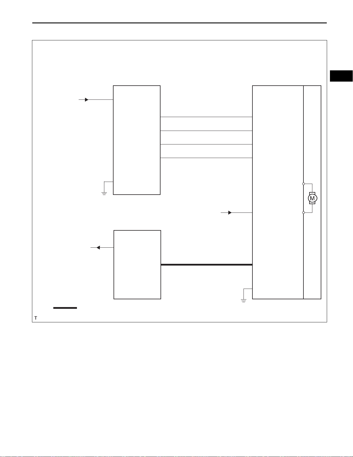
WIRING DIAGRAM
WS–25
with Jam Protection:
from POWER fuse
M1
Power Window
Master Switch
6
B
1
E
Main Body ECU
UP
LED
AUTO
DN
8
3
4
5
from PWR fuse
I5
Power Window Regulator
Motor Assembly (Front LH)
10
UP1
5
LED
4
AUTO
7
DWN1
2
B
WS
to PWR Relay
: LIN Communication Line
18
PWS
LIN2
10
9
LIN
1
E
B140744E01
WS
WS–26
WINDSHIELD / WINDOWGLASS – POWER WINDOW CONTROL SYSTEM
INSPECTION PROCEDURE
INSPECT POWER WINDOW REGULATOR MASTER SWITCH ASSEMBLY
1
B108710
(a) Measure the resistance according to the value(s) in the
table below.
Standard resistance
Tester Connection Condition Specified Condition
8 (UP) - 1 (E) - 4 (AUTO) Auto UP Below 1 Ω
5 (DN) - 6 (B) Auto UP Below 1 Ω
8 (UP) - 1 (E) Manual UP Below 1 Ω
5 (DN) - 6 (B) Manual UP Below 1 Ω
8 (UP) - 5 (DN) - 6 (B) OFF Below 1 Ω
5 (DN) - 1 (E) Manual DOWN Below 1 Ω
8 (UP) - 6 (B) Manual DOWN Below 1 Ω
4 (AUTO) - 5 (DN) - 1 (E) Auto DOWN Below 1 Ω
8 (UP) - 6 (B) Auto DOWN Below 1 Ω
OK
CHECK WIRE HARNESS (WINDOW REGULATOR MASTER SWITCH - WINDOW
2
REGULATOR MOTOR)
M1
Power Window Regulator Master
Switch Assembly:
LED
AUTO
I5
Power Window Regulator Motor
(Front LH):
AUTO
DN
UP
LED
NG
REPLACE POWER WINDOW REGULATOR
MASTER SWITCH
(a) Disconnect the M1 and I5 connectors.
(b) Measure the resistance according to the value(s) in the
table below.
Standard resistance
Tester Connection Condition Specified Condition
M1-8 (UP) - I5-10 (UP1) Always Below 1 Ω
M1-3 (LED) - I5-5 (LED) Always Below 1 Ω
M1-4 (AUTO) - I5-4
(AUTO)
M1-5 (DN) - I5-7 (DWN1) Always Below 1 Ω
M1-8 (UP) - Body
ground
M1-3 (LED) - Body
ground
M1-4 (AUTO) - Body
ground
M1-5 (DN) - Body
ground
Always Below 1 Ω
Always 10 kΩ or higher
Always 10 kΩ or higher
Always 10 kΩ or higher
Always 10 kΩ or higher
DWN1
UP1
B137046E02
NG
REPAIR OR REPLACE HARNESS OR
CONNECTOR
OK
REPLACE DRIVER SIDE POWER WINDOW REGULATOR MOTOR ASSEMBLY
WINDSHIELD / WINDOWGLASS – POWER WINDOW CONTROL SYSTEM
WS–27
DTC B2313 Glass Position Initialization Incomplete
DESCRIPTION
The portion of the power window control system that is located in the driver door consists of a power
window master switch, regulator, and a motor with an integrated ECU. The driver door power window
regulator motor is controlled by the ECU when the power window master switch is operated (models with
jam protection).
When the ECU determines that the driver's door power window regulator motor assembly has not been
initialized, DTC B2313 is set.
NOTICE:
The power window control system uses a serial communication protocol (LIN) to communicate
with the main body ECU. Inspect the communication function by following HOW TO PROCEED
WITH TROUBLESHOOTING. Troubleshoot the power window control system after confirming that
the communication system is functioning properly.
HINT:
• Replacing the door glass or door glass run may cause a difference to exist between the current door
glass position and the position memorized in the ECU. In this case, the jam protection function may
work improperly. Return the system to the pre-initialized condition and reinitialize the system.
• To return the system to the pre-initialized condition:
Disconnect the power window regulator motor connector during power window operation. This will
return the motor to the pre-initialized condition.
DTC No. DTC Detection Condition Trouble Area
• Power window regulator motor (on driver
side)
• Power window regulator motor (on driver
side) not initialized
B2313
• The power window regulator motor (on
driver side) is not initialized
• The power window regulator motor (on
driver side) malfunctions
WS
INSPECTION PROCEDURE
NOTICE:
When using the intelligent tester to troubleshoot the LIN communication line: Connect the
intelligent tester to the vehicle, and turn the courtesy light switch on and off at 1.5 second
intervals until communication between the tester and vehicle begins.
CHECK DTC OUTPUT
1
(a) Turn the ignition switch off.
(b) Wait for at least 10 seconds, and then turn the ignition
switch on (IG).
(c) Check whether the DTC output recurs.
Result
Display (DTC Output) Proceed to
B2313 A
No output B
B
A
END
WS
WS–28
2
WINDSHIELD / WINDOWGLASS – POWER WINDOW CONTROL SYSTEM
SYSTEM INITIALIZE (POWER WINDOW CONTROL SYSTEM)
(a) Turn the ignition switch on (IG) and initialize the power
window regulator motor (on the driver side) (see page
WS-8).
(b) Turn the ignition switch off.
(c) Wait for at least 10 seconds, and then turn the ignition
switch on (IG).
(d) Check whether the DTC output recurs.
Display (DTC Output) Proceed to
No output A
B2313 B
END
B
A
REPLACE POWER WINDOW REGULATOR
MOTOR ASSEMBLY FRONT LH
WINDSHIELD / WINDOWGLASS – POWER WINDOW CONTROL SYSTEM
Power Window Master Switch Circuit
DESCRIPTION
This circuit transmits signal from the power window regulator master switch assembly to the power
window regulator switch.
WIRING DIAGRAM
WS–29
WS
M1
Power Window Regulator
Master Switch
16
PU
15
PD
6
B
12
RLU
13
RLD
10
RRU
18
RRD
from POWER fuse
from RR DOOR LH fuse
from RR DOOR RH fuse
from POWER fuse
H6
Power Window Regulator
Switch (Front RH)
3
B
5
SU
2
SD
K1
Power Window Regulator
Switch (Rea LH)
3
B
5
SU
2
SD
J1
Power Window Regulator
Switch (Rear RH)
3
B
5
SU
2
SD
4
U
1
D
4
U
1
D
4
U
1
D
H4
Power Window Regulator
Motor (Front RH)
K3
Power Window Regulator
Motor (Rear LH)
J3
Power Window Regulator
Motor (Rear RH)
DN
UP
AUTO
LED
I4
Power Window Regulator
Motor (Front LH)
12
*1
5 (4)
8 (3)
4
3
*1: without Jam Protection
1
E
*2: with Jam Protection
from PWR fuse
*1
*2
*2
*2
*2
( ): without Jam Protection
I5
Power Window Regulator
Motor (Front LH)
2
*2
B
7
DWN1
10
UP1
4
AUTO
5
LED
1
E
*2
B140723E01
WS
WS–30
WINDSHIELD / WINDOWGLASS – POWER WINDOW CONTROL SYSTEM
INSPECTION PROCEDURE
CHECK DTC OUTPUT
1
(a) Turn the ignition switch off.
(b) Wait for at least 10 seconds, and then turn the ignition
switch on (IG).
(c) Check whether the DTC output recurs.
Result
Display (DTC output) Proceed to
No output A
Output DTCs B
B
GO TO DTC CHART
A
INSPECT POWER WINDOW REGULATOR MASTER SWITCH ASSEMBLY
2
(a) Disconnect the M1 connector.
(b) Measure the voltage and resistance according to the
M1
E
B
value(s) in the table below.
Standard voltage
Tester Connection Condition Specified Condition
6 (B) - Body ground Ignition switch on (IG) 10 to 14 V
Standard resistance
B137060E01
Tester Connection Condition Specified Condition
1 (E) - Body ground Always Below 1 Ω
NG
REPAIR OR REPLACE HARNESS OR
CONNECTOR
OK
INSPECT POWER WINDOW REGULATOR MASTER SWITCH ASSEMBLY
3
(a) Measure the resistance according to the value(s) in the
table below.
Standard resistance:
(with Jam Protection)
Tester Connection Condition Specified Condition
B050518E04
8 (UP) - 1 (E) - 4 (AUTO)
5 (DN) - 6 (B) Below 1 Ω
8 (UP) - 1 (E)
5 (DN) - 6 (B) Below 1 Ω
8 (UP) - 5 (DN) - 6 (B) OFF Below 1 Ω
5 (DN) - 1 (E)
8 (UP) - 6 (B) Below 1 Ω
Auto UP
Manual UP
Manual DOWN
Below 1 Ω
Below 1 Ω
Below 1 Ω

WINDSHIELD / WINDOWGLASS – POWER WINDOW CONTROL SYSTEM
Tester Connection Condition Specified Condition
4 (AUTO) - 5 (DN) - 1 (E)
8 (UP) - 6 (B) Below 1 Ω
1 (E) - 10 (RRU)
1 (E) - 12 (RLU)
1 (E) - 13 (RLD)
1 (E) - 15 (PD)
1 (E) - 16 (PU)
1 (E) - 18 (RRD)
Auto DOWN
Lock/Unlock switch
(without Jam Protection)
Tester Connection Condition Specified Condition
1 (E) - 3 (UP)
1 (E) - 4 (DN) Below 1 Ω
1 (E) - 10 (RRU)
1 (E) - 12 (RLU)
1 (E) - 13 (RLD)
1 (E) - 15 (PD)
1 (E) - 16 (PU)
1 (E) - 18 (RRD)
OFF
Lock/Unlock switch
WS–31
Below 1 Ω
UNLOCK (Below 1 Ω)
→LOCK (10 kΩ or
higher)
Below 1 Ω
UNLOCK (Below 1 Ω)
→LOCK (10 kΩ or
higher)
WS
OK
CHECK WIRE HARNESS (POWER WINDOW MASTER SWITCH - FRONT LH, REAR LH/RH
4
SWITCH)
M1
Power Window Regulator Master
Switch Assembly:
RLU PD
RRU
RLD
H6 (K1, J1)
Power Window Switch
(Front RH, Rear LH/RH):
RRD
PU
B137067E01
NG
REPLACE POWER WINDOW REGULATOR
MASTER SWITCH ASSEMBLY
(a) Disconnect the M1 and H6 (K1, J1) connectors.
(b) Measure the resistance according to the value(s) in the
table below.
Standard resistance:
Front RH side
Tester Connection Condition Specified Condition
M1-16 (PU) - H6-5 (SU) Always Below 1 Ω
M1-15 (PD) - H6-2 (SD) Always Below 1 Ω
M1-16 (PU) - Body
ground
M1-15 (PD) - Body
ground
Always 10 kΩ or higher
Always 10 kΩ or higher
Rear LH side
Tester Connection Condition Specified Condition
M1-12 (RLU) - K1-5 (SU) Always Below 1 Ω
M1-13 (RLD) - K1-2 (SD) Always Below 1 Ω
M1-12 (RLU) - Body
ground
M1-13 (RLD) - Body
ground
Always 10 kΩ or higher
Always 10 kΩ or higher
Rear RH side

WS
WS–32
WINDSHIELD / WINDOWGLASS – POWER WINDOW CONTROL SYSTEM
Tester Connection Condition Specified Condition
M1-10 (RRU) - J1-5 (SU) Always Below 1 Ω
M1-18 (RRD) - J1-2 (SD) Always Below 1 Ω
M1-10 (RRU) - Body
ground
M1-18 (RRD) - Body
ground
Always 10 kΩ or higher
Always 10 kΩ or higher
NG
REPAIR OR REPLACE HARNESS OR
CONNECTOR
OK
PROCEED TO NEXT CIRCUIT INSPECTION SHOWN IN PROBLEM SYMPTOMS TABLE

WINDSHIELD / WINDOWGLASS – POWER WINDOW CONTROL SYSTEM
Front Passenger Side Power Window Switch Power Source Circuit
DESCRIPTION
This circuit supplies power to operate the power window regulator switch assembly (Front RH).
WS–33
WIRING DIAGRAM
C
from POWER fuse
H6
Power Window Regulator Switch
Assembly (Front RH)
3
B
B137059E01
WS
INSPECTION PROCEDURE
CHECK WIRE HARNESS (POWER WINDOW REGULATOR SWITCH - BATTERY AND
1
BODY GROUND)
(a) Disconnect the H6 connector.
(b) Measure the voltage according to the value(s) in the
H6
B
B137048E01
OK
PROCEED TO NEXT CIRCUIT INSPECTION SHOWN IN PROBLEM SYMPTOMS TABLE
table below.
Standard voltage
Tester Connection Condition Specified Condition
3 (B) - Body ground Ignition switch on (IG) 10 to 14 V
NG
REPAIR OR REPLACE HARNESS OR
CONNECTOR

WS–34
WINDSHIELD / WINDOWGLASS – POWER WINDOW CONTROL SYSTEM
Rear Power Window Switch LH Circuit
DESCRIPTION
This circuit supplies power to operate the power window regulator switch assembly (Rear LH).
WS
WIRING DIAGRAM
C
from RR DOOR LH fuse
K1
Power Window Regulator Switch
Assembly (Rear LH)
3
B
B137059E02
INSPECTION PROCEDURE
CHECK WIRE HARNESS (POWER WINDOW REGULATOR SWITCH - BATTERY AND
1
BODY GROUND)
(a) Disconnect the K1 connector.
(b) Measure the voltage according to the value(s) in the
K1
B
B137048E02
OK
PROCEED TO NEXT CIRCUIT INSPECTION SHOWN IN PROBLEM SYMPTOMS TABLE
table below.
Standard voltage
Tester Connection Condition Specified Condition
3 (B) - Body ground Ignition switch on (IG) 10 to 14 V
NG
REPAIR OR REPLACE HARNESS OR
CONNECTOR

WINDSHIELD / WINDOWGLASS – POWER WINDOW CONTROL SYSTEM
Rear Power Window Switch RH Circuit
DESCRIPTION
This circuit supplies power to operate the power window regulator switch (Rear RH).
WS–35
WIRING DIAGRAM
C
from RR DOOR RH fuse
J1
Power Window Regulator Switch
Assembly (Rear RH)
3
B
B137059E03
WS
INSPECTION PROCEDURE
CHECK WIRE HARNESS (POWER WINDOW REGULATOR SWITCH - BATTERY AND
1
BODY GROUND)
(a) Disconnect the J1 connector.
(b) Measure the voltage according to the value(s) in the
J1
B
B137048E03
OK
PROCEED TO NEXT CIRCUIT INSPECTION SHOWN IN PROBLEM SYMPTOMS TABLE
table below.
Standard voltage
Tester Connection Condition Specified Condition
3 (B) - Body ground Ignition switch on (IG) 10 to 14 V
NG
REPAIR OR REPLACE HARNESS OR
CONNECTOR

WS
WS–36
WINDSHIELD / WINDOWGLASS – POWER WINDOW CONTROL SYSTEM
Driver Side Power Window Motor Circuit
DESCRIPTION
This circuit transmits signals from the power window regulator master switch assembly to the power
window regulator motor (Front LH).
WIRING DIAGRAM
with Jam Protection:
M1
Power Window Regulator Master
I5
Power Window Regulator Motor (Front LH)
Switch Assembly
from PWR fuse
C
without Jam Protection:
I4
Power Window Regulator Motor (Front LH)
2
B
UP1
DWN1
AUTO
E
10
7
4
1
8
UP
5
DN
4
AUTO
B137064E01
M1
Power Window Regulator Master
Switch Assembly
2
1
C
3
UP
4
DN
B137065E04

WINDSHIELD / WINDOWGLASS – POWER WINDOW CONTROL SYSTEM
INSPECTION PROCEDURE
INSPECT POWER WINDOW REGULATOR MOTOR
1
Motor Gear
Counterclockwise
Clockwise
Counterclockwise
Motor Gear
Clockwise
B127535E01
B137055E01
without Jam protection:
(a) Remove the power window motor.
(1) Apply battery voltage to the motor connector
according to the table below.
NOTICE:
Do not apply battery voltage to any terminals
except terminals 1 and 2.
Standard
Measurement Condition Specified Condition
Battery positive (+) → Terminal 2
Battery negative (-) → Terminal 1
Battery positive (+) → Terminal 1
Battery negative (-) → Terminal 2
Motor gear rotates clockwise
Motor gear rotates counterclockwise
(b) with Jam protection:
Remove the power window motor.
(1) Apply battery voltage to the motor connector
according to the table below.
NOTICE:
Do not apply battery voltage to any terminals
except terminals 1, 2, 4, 7 and 10.
Standard
Switch Condition Measurement Condition Specified Condition
Battery positive (+) →
Motor gear rotates
clockwise
Motor gear rotates
counterclockwise
Motor gear rotates
clockwise
Motor gear rotates
counterclockwise
Manual Operation
Auto Operation
Terminal 2 (PWR)
Battery negative (-) →
Terminal 1 (E), 7 (DN)
Battery positive (+) →
Terminal 2 (PWR)
Battery negative (-) →
Terminal 1 (E), 10 (UP)
Battery positive (+) →
Terminal 2 (PWR)
Battery negative (-) →
Terminal 1 (E), 4
(AUTO), 7 (DN)
Battery positive (+) →
Terminal 2 (PWR)
Battery negative (-) →
Terminal 1 (E), 4
(AUTO), 10 (UP)
WS–37
WS
OK
NG
REPLACE POWER WINDOW REGULATOR
MOTOR

WS
WS–38
2
CHECK WIRE HARNESS (WINDOW REGULATOR MOTOR - WINDOW REGULATOR
WINDSHIELD / WINDOWGLASS – POWER WINDOW CONTROL SYSTEM
MASTER SWITCH)
M1
Power Window Regulator Master
Switch Assembly:
UP DN
I4
Power Window Regulator Motor
(Front LH):
(a) without Jam protection:
Disconnect the M1 and I4 connectors.
(1) Measure the resistance according to the value(s) in
the table below.
Standard resistance
Tester Connection Condition Specified Condition
M1-3 (UP) - I4-2 Always Below 1 Ω
M1-4 (DN) - I4-1 Always Below 1 Ω
M1-3 (UP) - Body
ground
M1-4 (DN) - Body
ground
Always 10 kΩ or higher
Always 10 kΩ or higher
M1
Power Window Regulator Master
Switch Assembly:
DN
I5
Power Window Regulator Motor
(Front LH):
B137061E01
UP
B137046E01
(b) with Jam protection:
Disconnect the M1 and I5 connectors.
(1) Measure the resistance according to the value(s) in
the table below.
Standard resistance
Tester Connection Condition Specified Condition
M1-8 (UP) - I5-10 Always Below 1 Ω
M1-5 (DN) - I5-7 Always Below 1 Ω
M1-8 (UP) - Body
ground
M1-5 (DN) - Body
ground
NG
REPAIR OR REPLACE HARNESS OR
Always 10 kΩ or higher
Always 10 kΩ or higher
CONNECTOR
OK
PROCEED TO NEXT CIRCUIT INSPECTION SHOWN IN PROBLEM SYMPTOMS TABLE

WINDSHIELD / WINDOWGLASS – POWER WINDOW CONTROL SYSTEM
WS–39
Front Passenger Side Power Window Motor Circuit
DESCRIPTION
This circuit transmits signals from the power window regulator switch assembly (Front RH) to the power
window regulator motor (Front RH).
WIRING DIAGRAM
H6
Power Window Regulator Switch
Assembly (Front RH)
H4
Power Window Regulator Motor (Front RH)
WS
2
1
C
INSPECTION PROCEDURE
INSPECT POWER WINDOW REGULATOR MOTOR
1
Motor Gear
Clockwise
Couterclockwise
B127536E02
4
U
1
D
B137065E01
(a) Remove the power window motor.
(b) Apply battery voltage to the motor connector according
to the table below.
NOTICE:
Do not apply battery voltage to any terminals except
terminals 1 and 2.
Standard
Measurement Condition Specified Condition
Battery positive (+) → Terminal 1
Battery negative (-) → Terminal 2
Battery positive (+) → Terminal 2
Battery negative (-) → Terminal 1
Motor gear rotates clockwise
Motor gear rotates counterclockwise
OK
NG
REPLACE POWER WINDOW REGULATOR
MOTOR

WS
WS–40
2
CHECK WIRE HARNESS (WINDOW REGULATOR MOTOR - POWER WINDOW
WINDSHIELD / WINDOWGLASS – POWER WINDOW CONTROL SYSTEM
REGULATOR SWITCH)
H6
Power Window Regulator
Switch Assembly (Front RH):
DU
H4
Power Window Regulator
Motor (Front RH):
(a) Disconnect the H6 and H4 connectors.
(b) Measure the resistance according to the value(s) in the
table below.
Standard resistance
Tester Connection Condition Specified Condition
H6-4 (U) - H4-2 Always Below 1 Ω
H6-1 (D) - H4-1 Always Below 1 Ω
H6-4 (U) - Body ground Always 10 kΩ or higher
H6-1 (D) - Body ground Always 10 kΩ or higher
NG
REPAIR OR REPLACE HARNESS OR
CONNECTOR
B137066E01
OK
PROCEED TO NEXT CIRCUIT INSPECTION SHOWN IN PROBLEM SYMPTOMS TABLE

WINDSHIELD / WINDOWGLASS – POWER WINDOW CONTROL SYSTEM
WS–41
Rear Power Window Motor LH Circuit
DESCRIPTION
This circuit transmits signals from the power window regulator switch assembly (Rear LH) to the power
window regulator motor (Rear LH).
WIRING DIAGRAM
K1
Power Window Regulator Switch
Assembly (Rear LH)
K3
Power Window Regulator Motor (Rear LH)
WS
1
2
C
INSPECTION PROCEDURE
INSPECT POWER WINDOW REGULATOR MOTOR
1
Motor Gear
Clockwise
Couterclockwise
B127536E02
4
U
1
D
B137065E02
(a) Remove the power window motor.
(b) Apply battery voltage to the motor connector according
to the table below.
NOTICE:
Do not apply battery voltage to any terminals except
terminals 1 and 2.
Standard
Measurement Condition Specified Condition
Battery positive (+) → Terminal 1
Battery negative (-) → Terminal 2
Battery positive (+) → Terminal 2
Battery negative (-) → Terminal 1
Motor gear rotates clockwise
Motor gear rotates counterclockwise
OK
NG
REPLACE POWER WINDOW REGULATOR
MOTOR

WS
WS–42
2
CHECK WIRE HARNESS (WINDOW REGULATOR MOTOR - WINDOW REGULATOR
WINDSHIELD / WINDOWGLASS – POWER WINDOW CONTROL SYSTEM
SWITCH)
K1
Power Window Regulator
Switch Assembly (Rear LH):
DU
K3
Power Window Regulator
Motor (Rear LH):
(a) Disconnect the K1 and K3 connectors.
(b) Measure the resistance according to the value(s) in the
table below.
Standard resistance
Tester Connection Condition Specified Condition
K1-4 (U) - K3-1 Always Below 1 Ω
K1-1 (D) - K3-2 Always Below 1 Ω
K1-4 (U) - Body ground Always 10 kΩ or higher
K1-1 (D) - Body ground Always 10 kΩ or higher
NG
REPAIR OR REPLACE HARNESS OR
CONNECTOR
B137066E02
OK
PROCEED TO NEXT CIRCUIT INSPECTION SHOWN IN PROBLEM SYMPTOMS TABLE

WINDSHIELD / WINDOWGLASS – POWER WINDOW CONTROL SYSTEM
WS–43
Rear Power Window Motor RH Circuit
DESCRIPTION
This circuit transmits signals from the power window regulator switch assembly (Rear RH) to the power
window regulator motor (Rear RH).
WIRING DIAGRAM
J1
Power Window Regulator Switch
Assembly (Rear RH)
J3
Power Window Regulator Motor (Rear RH)
WS
1
2
C
INSPECTION PROCEDURE
INSPECT POWER WINDOW REGULATOR MOTOR
1
Motor Gear
Counterclockwise
Clockwise
B127535E01
4
U
1
D
B137065E05
(a) Remove the power window motor.
(b) Apply battery voltage to the motor connector according
to the table below.
NOTICE:
Do not apply battery voltage to any terminals except
terminals 1 and 2.
Standard
Measurement Condition Specified Condition
Battery positive (+) → Terminal 2
Battery negative (-) → Terminal 1
Battery positive (+) → Terminal 1
Battery negative (-) → Terminal 2
Motor gear rotates clockwise
Motor gear rotates counterclockwise
OK
NG
REPLACE POWER WINDOW REGULATOR
MOTOR

WS
WS–44
2
CHECK WIRE HARNESS (WINDOW REGULATOR MOTOR - WINDOW REGULATOR
WINDSHIELD / WINDOWGLASS – POWER WINDOW CONTROL SYSTEM
SWITCH)
J1
Power Window Regulator
Switch Assembly (Rear RH):
DU
J3
Power Window Regulator
Motor (Rear RH):
(a) Disconnect the J1 and J3 connectors.
(b) Measure the resistance according to the value(s) in the
table below.
Standard resistance
Tester Connection Condition Specified Condition
J1-4 (U) - J3-1 Always Below 1 Ω
J1-1 (D) - J3-2 Always Below 1 Ω
J1-4 (U) - Body ground Always 10 kΩ or higher
J1-1 (D) - Body ground Always 10 kΩ or higher
NG
REPAIR OR REPLACE HARNESS OR
CONNECTOR
B137066E03
OK
PROCEED TO NEXT CIRCUIT INSPECTION SHOWN IN PROBLEM SYMPTOMS TABLE

WS–42
WINDSHIELD / WINDOWGLASS – POWER WINDOW MASTER SWITCH
POWER WINDOW MASTER
SWITCH
INSPECTION
WS
B050518E04
1. INSPECT POWER WINDOW MASTER SWITCH (w/
Jam Protection Function)
(a) Measure the resistance when the switch is operated
according to the value(s) in the table below.
Standard resistance
Tester Connection Switch Condition Specified Condition
8 (UP) - 1 (E) - 4 (AUTO)
5 (DN) - 6 (B) Below 1 Ω
8 (UP) - 1 (E)
5 (DN) - 6 (B) Below 1 Ω
8 (UP) - 5 (DN) - 6 (B) OFF Below 1 Ω
5 (DN) - 1 (E)
8 (UP) - 6 (B) Below 1 Ω
4 (AUTO) - 5 (DN) - 1 (E)
8 (UP) - 6 (B) Below 1 Ω
1 (E) - 10 (RRU)
1 (E) - 12 (RLU)
1 (E) - 13 (RLD)
1 (E) - 15 (PD)
1 (E) - 16 (PU)
1 (E) - 18 (RRD)
Auto UP
Manual UP
Manual DOWN
Auto DOWN
Lock/Unlock switch
Below 1 Ω
Below 1 Ω
Below 1 Ω
Below 1 Ω
UNLOCK (Below 1 Ω) →
LOCK (10 kΩ or higher)
B050518E04
2. INSPECT POWER WINDOW MASTER SWITCH (w/o
Jam Protection Function)
(a) Measure the resistance when the switch is operated
according to the value(s) in the table below.
Standard resistance
Tester Connection Switch Condition Specified Condition
1 (E) - 3 (DU)
1 (E) - 4 (DD) Below 1 Ω
1 (E) - 10 (RRU)
1 (E) - 12 (RLU)
1 (E) - 13 (RLD)
1 (E) - 15 (PD)
1 (E) - 16 (PU)
1 (E) - 18 (RRD)
OFF
Lock/Unlock switch
Below 1 Ω
UNLOCK (Below 1 Ω) →
LOCK (10 kΩ or higher)

WINDSHIELD / WINDOWGLASS – FRONT PASSENGER SIDE POWER WINDOW SWITCH
FRONT P ASSENGER SIDE POWER
WINDOW SWITCH
INSPECTION
WS–43
B102538E01
1. INSPECT POWER WINDOW SWITCH
(a) Remove the power window switch.
(b) Measure the resistance when the switch is operated
according to the value(s) in the table below.
Standard resistance
Tester Connection Switch Condition Specified Condition
1 (D) - 2 (SD)
3 (B) - 4 (U) Below 1 Ω
1 (D) - 2 (SD)
4 (U) - 5 (SU) Below 1 Ω
4 (U) - 5 (SU)
1 (D) - 3 (B) Below 1 Ω
UP
OFF
DOWN
Below 1 Ω
Below 1 Ω
Below 1 Ω
WS

WS
WS–44
WINDSHIELD / WINDOWGLASS – REAR POWER WINDOW SWITCH
REAR POWER WINDOW SWITCH
INSPECTION
1. INSPECT POWER WINDOW SWITCH (for Rear RH)
(a) Remove the power window switch.
(b) Measure the resistance when the switch is operated
according to the value(s) in the table below.
Standard resistance
B102538E01
B102538E01
Tester Connection Switch Condition Specified Condition
1 (D) - 2 (SD)
3 (B) - 4 (U) Below 1 Ω
1 (D) - 2 (SD)
4 (U) - 5 (SU) Below 1 Ω
4 (U) - 5 (SU)
1 (D) - 3 (B) Below 1 Ω
UP
OFF
DOWN
2. REMOVE POWER WINDOW SWITCH (for Rear LH)
(a) Remove the power window switch.
(b) Measure the resistance when the switch is operated
according to the value(s) in the table below.
Standard resistance
Tester Connection Switch Condition Specified Condition
1 (D) - 2 (SD)
3 (B) - 4 (U) Below 1 Ω
1 (D) - 2 (SD)
4 (U) - 5 (SU) Below 1 Ω
4 (U) - 5 (SU)
1 (D) - 3 (B) Below 1 Ω
UP
OFF
DOWN
Below 1 Ω
Below 1 Ω
Below 1 Ω
Below 1 Ω
Below 1 Ω
Below 1 Ω

WINDSHIELD / WINDOWGLASS – POWER WINDOW REGULATOR MOTOR
BODYWINDSHIELD / WINDOWGLASS
POWER WINDOW REGULATOR MOTOR
COMPONENTS
WS–45
for Front Door:
FRONT DOOR GLASS SUB-ASSEMBLY
FRONT DOOR INNER GLASS WEATHERSTRIP
FRONT DOOR SERVICE
HOLE COVER
WS
FRONT DOOR LOWER FRAME BRACKET GARNISH
BUTYL TAPE
FRONT DOOR WINDOW
REGULATOR SUB-ASSEMBLY
FRONT DOOR INSIDE
HANDLE BEZEL PLUG
ASSIST GRIP COVER
COURTESY LIGHT ASSEMBLY
N*m (kgf*cm, ft.*lbf)
Non-reusable part
Apply MP grease
5.5 (56, 49 in.*lbf)
: Specified torque
8.0 (82, 71 in.*lbf)
5.4 (55, 48 in.*lbf)
FRONT NO. 1
SPEAKER ASSEMBLY
FRONT POWER WINDOW REGULATOR
MOTOR ASSEMBLY
FRONT DOOR TRIM BOARD SUB-ASSEMBLY
B142333E01

WS–46
for Rear Door:
WINDSHIELD / WINDOWGLASS – POWER WINDOW REGULATOR MOTOR
NO. 1 DOOR SCUFF PLATE CLAMP
WS
REAR DOOR INNER GLASS WEATHERSTRIP
REAR DOOR QUARTER
WINDOW GLASS
REAR DOOR GLASS SUB-ASSEMBLY
REAR DOOR LOWER WINDOW
FRAME SUB-ASSEMBLY
REAR DOOR GLASS RUN
REAR DOOR INSIDE
HANDLE BEZEL PLUG
DOOR ASSIST
GRIP COVER
N*m (kgf*cm, ft.*lbf)
Non-reusable part
: Specified torque
BUTYL TAPE
REAR DOOR SERVICE HOLE COVER
REAR DOOR TRIM BOARD SUB-ASSEMBLY
5.4 (55, 48 in.*lbf)
8.0 (82, 71 in.*lbf)
REAR DOOR WINDOW
REGULATOR SUB-ASSEMBLY
REAR POWER WINDOW REGULATOR
MOTOR ASSEMBLY
Apply MP grease
B142334E01

WINDSHIELD / WINDOWGLASS – POWER WINDOW REGULATOR MOTOR
REMOVAL
1. REMOVE FRONT DOOR LOWER FRAME BRACKET
GARNISH (See page ED-14)
2. REMOVE FRONT DOOR INSIDE HANDLE BEZEL
PLUG (See page ED-14)
3. REMOVE ASSIST GRIP COVER (See page ED-15)
4. REMOVE COURTESY LIGHT ASSEMBLY (See page
ED-15)
5. REMOVE FRONT DOOR TRIM BOARD SUBASSEMBLY (See page ED-15)
6. REMOVE FRONT DOOR INNER GLASS
WEATHERSTRIP (See page ED-16)
7. REMOVE FRONT NO. 1 SPEAKER ASSEMBLY (See
page AV-155)
8. REMOVE FRONT DOOR SERVICE HOLE COVER
(See page ED-17)
WS–47
WS
9. REMOVE FRONT DOOR GLASS SUB-ASSEMBLY
(See page ED-17)
10. REMOVE FRONT DOOR WINDOW REGULATOR
SUB-ASSEMBLY (See page ED-18)
11. REMOVE FRONT POWER WINDOW REGULATOR
MOTOR ASSEMBLY (See page ED-18)
12. REMOVE REAR DOOR INSIDE HANDLE BEZEL
PLUG (See page ED-38)
13. REMOVE DOOR ASSIST GRIP COVER (See page ED-
38)
14. REMOVE REAR DOOR TRIM BOARD SUBASSEMBLY (See page ED-39)
15. REMOVE REAR DOOR INNER GLASS
WEATHERSTRIP (See page ED-40)
16. REMOVE REAR DOOR SERVICE HOLE COVER (See
page ED-41)
17. REMOVE REAR DOOR GLASS RUN (See page ED-
42)
18. REMOVE REAR DOOR LOWER WINDOW FRAME
SUB-ASSEMBLY (See page ED-42)
19. REMOVE REAR DOOR QUARTER WINDOW GLASS
(See page ED-43)
20. REMOVE REAR DOOR GLASS SUB-ASSEMBL Y (See
page ED-43)
21. REMOVE REAR DOOR WINDOW REGULATOR SUBASSEMBLY (See page ED-43)
22. REMOVE REAR POWER WINDOW REGULATOR
MOTOR ASSEMBLY (See page ED-43)

WS
WS–48
Motor Gear
WINDSHIELD / WINDOWGLASS – POWER WINDOW REGULATOR MOTOR
INSPECTION
Motor Gear
Clockwise
Couterclockwise
B127536E02
Counterclockwise
Clockwise
B127535E01
1. INSPECT POWER WINDOW REGULATOR MOTOR
(FRONT RH)
(a) Apply battery voltage to the motor connector
according to the table below.
NOTICE:
Do not apply battery voltage to any terminals
except terminals 1 and 2.
Standard
Measurement Condition Specified Condition
Battery positive (+) → Terminal 1
Battery negative (-) → Terminal 2
Battery positive (+) → Terminal 2
Battery negative (-) → Terminal 1
Motor gear rotates counterclockwise
2. INSPECT POWER WINDOW REGULATOR MOTOR
(FRONT LH)
(a) without Jam protection:
Apply battery voltage to the motor connector
according to the table below.
NOTICE:
Do not apply battery voltage to any terminals
except terminals 1 and 2.
Standard
Measurement Condition Specified Condition
Battery positive (+) → Terminal 2
Battery negative (-) → Terminal 1
Battery positive (+) → Terminal 1
Battery negative (-) → Terminal 2
Motor gear rotates counterclockwise
Motor gear rotates clockwise
Motor gear rotates clockwise
Counterclockwise
Motor Gear
Clockwise
B137055E01
(b) with Jam protection:
Apply battery voltage to the motor connector
according to the table below.
NOTICE:
Do not apply battery voltage to any terminals
except terminals 1, 2, 4, 7 and 10.
Standard
Switch Condition Measurement Condition Specified Condition
Manual Operation
Auto Operation
Battery positive (+) →
Terminal 2 (PWR)
Battery negative (-) →
Terminal 1 (E), 7 (DN)
Battery positive (+) →
Terminal 2 (PWR)
Battery negative (-) →
Terminal 1 (E), 10 (UP)
Battery positive (+) →
Terminal 2 (PWR)
Battery negative (-) →
Terminal 1 (E), 4
(AUTO), 7 (DN)
Battery positive (+) →
Terminal 2 (PWR)
Battery negative (-) →
Terminal 1 (E), 4 (AUTO)
10 (UP)
Motor gear rotates
clockwise
Motor gear rotates
counterclockwise
Motor gear rotates
clockwise
Motor gear rotates
counterclockwise

Clockwise
Couterclockwise
Motor Gear
WINDSHIELD / WINDOWGLASS – POWER WINDOW REGULATOR MOTOR
3. INSPECT POWER WINDOW REGULATOR MOTOR
Motor Gear
(REAR RH)
(a) Apply battery voltage to the motor connector
according to the table below.
NOTICE:
Do not apply battery voltage to any terminals
except terminals 1 and 2.
Standard
B127536E02
Measurement Condition Specified Condition
Battery positive (+) → Terminal 2
Battery negative (-) → Terminal 1
Battery positive (+) → Terminal 1
Battery negative (-) → Terminal 2
Motor gear rotates clockwise
Motor gear rotates counterclockwise
4. INSPECT POWER WINDOW REGULATOR MOTOR
(REAR LH)
(a) Apply battery voltage to the motor connector
according to the table below.
NOTICE:
Counterclockwise
Do not apply battery voltage to any terminals
except terminals 1 and 2.
Standard
Clockwise
B127535E01
Measurement Condition Specified Condition
Battery positive (+) → Terminal 1
Battery negative (-) → Terminal 2
Battery positive (+) → Terminal 2
Battery negative (-) → Terminal
Motor gear rotates clockwise
Motor gear rotates counterclockwise
WS–49
WS

WS
WS–50
WINDSHIELD / WINDOWGLASS – POWER WINDOW REGULATOR MOTOR
INSTALLATION
1. INSTALL REAR POWER WINDOW REGULATOR
MOTOR ASSEMBLY (See page ED-51)
2. INSTALL REAR DOOR WINDOW REGULATOR SUBASSEMBLY (See page ED-51)
3. INST ALL REAR DOOR GLASS RUN (See page ED-52)
4. INST ALL REAR DOOR GLASS SUB-ASSEMBLY (See
page ED-52)
5. INSTALL REAR DOOR QUARTER WINDOW GLASS
(See page ED-52)
6. INSTALL REAR DOOR LOWER WINDOW FRAME
SUB-ASSEMBLY (See page ED-52)
7. INSTALL REAR DOOR SERVICE HOLE COVER (See
page ED-53)
8. INSTALL REAR DOOR INNER GLASS
WEATHERSTRIP (See page ED-54)
9. INSTALL REAR DOOR TRIM BOARD SUBASSEMBLY (See page ED-55)
10. INSTALL DOOR ASSIST GRIP COVER (See page ED-
56)
11. INSTALL REAR DOOR INSIDE HANDLE BEZEL
PLUG (See page ED-56)
12. INITIALIZATION POWER WINDOW CONTROL
SYSTEM
(See page WS-8)
13. INSTALL FRONT POWER WINDOW REGULATOR
MOTOR ASSEMBLY (See page ED-31)
14. INSTALL FRONT DOOR WINDOW REGULATO R SUBASSEMBLY (See page ED-31)
15. INSTALL FRONT DOOR GLASS SUB-ASSEMBLY
(See page ED-31)
16. INST ALL FRONT DOOR SERVICE HOLE COVER (See
page ED-32)
17. INSTALL FRONT NO. 1 SPEAKER ASSEMBLY (See
page AV-157)
18. INSTALL FRONT DOOR INNER GLASS
WEATHERSTRIP (See page ED-32)
19. INSTALL FRONT DOOR TRIM BOARD SUBASSEMBLY (See page ED-33)
20. INSTALL COURTESY LIGHT ASSEMBLY (See page
ED-34)
21. INSTALL ASSIST GRIP COVER (See page ED-34)
22. INSTALL FRONT DOOR INSIDE HANDLE BEZEL
PLUG (See page ED-34)

WINDSHIELD / WINDOWGLASS – POWER WINDOW REGULATOR MOTOR
23. INSTALL FRONT DOOR LOWER FRAME BRACKET
GARNISH (See page ED-34)
24. INITIALIZE POWER WINDOW CONTROL SYSTEM
(See page WS-8)
WS–51
WS

WINDSHIELD / WINDOWGLASS – WINDSHIELD GLASS
BODYWINDSHIELD / WINDOWGLASS
WINDSHIELD GLASS
COMPONENTS
WS–51
FRONT ASSIST GRIP
SUB-ASSEMBLY
VISOR BRACKET
COVER
VISOR ASSEMBLY RH
FRONT PILLAR
GARNISH CLIP
FRONT PILLAR
GARNISH RH
ASSIST GRIP COVER
VISOR HOLDER
FRONT DOOR OPENING
TRIM WEATHERSTRIP RH
FRONT WIPER ARM AND
BLADE ASSEMBLY RH
ROOF HEADLINING ASSEMBLY
ROOF CONSOLE BOX
ASSEMBLY
VISOR HOLDER
VISOR ASSEMBLY LH
VISOR BRACKET COVER
FRONT PILLAR
GARNISH CLIP
WS
FRONT ASSIST GRIP
SUB-ASSEMBLY
ASSIST GRIP COVER
N*m (kgf*cm, ft.*lbf)
Non-reusable part
20 (204, 15)
FRONT PILLAR GARNISH LH
: Specified torque
COWL TOP VENTILATOR LOUVER SUB-ASSEMBLY
20 (204, 15)
FRONT DOOR OPENING
TRIM WEATHERSTRIP LH
FRONT WIPER ARM AND BLADE ASSEMBLY LH
FRONT FENDER TO COWL SIDE SEAL RH
FRONT FENDER TO COWL SIDE SEAL LH
B142346E01

WS–52
WINDSHIELD / WINDOWGLASS – WINDSHIELD GLASS
WS
without EC Mirror:
TMC made:
INNER REAR VIEW MIRROR
ASSEMBLY
NO. 1 WINDSHIELD GLASS STOPPER
NO. 2 WINDSHIELD GLASS STOPPER
NO. 2 WINDSHIELD GLASS STOPPER
without EC Mirror:
TMMK made:
1.8 (18, 16 in.*lbf)
INNER REAR VIEW MIRROR
ASSEMBLY
*2
*1
*2
with EC Mirror:
INNER REAR VIEW
MIRROR STAY
HOLDER COVER
1.8 (18, 16 in.*lbf)
INNER REAR VIEW MIRROR
ASSEMBLY
WINDSHIELD GLASS
WINDSHIELD GLASS RETAINER
*1: 1-Piece type
WINDSHIELD MOULDING
WINDOW GLASS ADHESIVE DAM
WINDSHIELD GLASS RETAINER
*2: 2-Piece type
Non-reusable part
N*m (kgf*cm, ft.*lbf)
WINDSHIELD GLASS ASSEMBLY
: Specified torque
B136128E01

WINDSHIELD / WINDOWGLASS – WINDSHIELD GLASS
REMOVAL
1. DISCONNECT CABLE FROM NEGATIVE BATTERY
TERMINAL
2. REMOVE FRONT WIPER ARM AND BLADE
ASSEMBLY LH (See page WW-9)
3. REMOVE FRONT WIPER ARM AND BLADE
ASSEMBLY RH (See page WW-9)
4. REMOVE FRONT FENDER TO COWL SIDE SEAL LH
(See page WW-9)
5. REMOVE FRONT FENDER TO COWL SIDE SEAL RH
(See page WW-9)
6. REMOVE COWL TOP VENTILATOR LOUVER SUBASSEMBLY (See page WW-10)
7. REMOVE INNER REAR VIEW MIRROR ASSEMBLY
(for TMC Made without EC Mirror) (See page MI-11)
8. REMOVE INNER REAR VIEW MIRROR ASSEMBLY
(for TMMK Made without EC Mirror) (See page MI-11)
WS–53
WS
9. REMOVE INNER REAR VIEW MIRROR STAY
HOLDER COVER (w/ EC Mirror) (See page MI-11)
10. REMOVE INNER REAR VIEW MIRROR ASSEMBLY
(w/ EC Mirror) (See page MI-12)
11. REMOVE FRONT DOOR OPENING TRIM
WEATHERSTRIP LH
12. REMOVE FRONT DOOR OPENING TRIM
WEATHERSTRIP RH
13. REMOVE FRONT PILLAR GARNISH LH (See page IR-
27)
14. REMOVE FRONT PILLAR GARNISH RH (See page IR-
27)
15. REMOVE ROOF CONSOLE BOX ASSEMBLY (See
page IR-28)
16. REMOVE VISOR ASSEMBLY LH (See page IR-28)
17. REMOVE VISOR ASSEMBLY RH (See page IR-29)
18. REMOVE VISOR HOLDER (See page IR-29)
19. REMOVE FRONT ASSIST GRIP SUB-ASSEMBLY
(See page IR-29)
20. REMOVE ROOF HEADLINING ASSEMBLY (w/o
Sliding Roof)
It is not necessary to completely remove the roof
headlining assembly. Slightly lower the front section of
the roof headlining assembly so that the windshield glass
can be removed (See page IR-31).

WS
WS–54
Windshield Glass
Moulding
WINDSHIELD / WINDOWGLASS – WINDSHIELD GLASS
21. REMOVE ROOF HEADLINING ASSEMBL Y (w/ Sliding
Roof)
It is not necessary to completely remove the roof
headlining assembly. Slightly lower the front section of
the roof headlining assembly so that the windshield glass
can be removed (See page IR-32).
22. REMOVE WINDSHIELD MOULDING
Cut
(a) Using a knife, cut off the moulding, as shown in the
illustration.
Body
NOTICE:
• Do not damage the vehicle body with the
knife.
• If the vehicle body is damaged, repair the
damaged portion by applying an anti-rust
coating after removing the windshield glass.
(b) Remove the remaining moulding from the
windshield glass.
HINT:
When removing the moulding, make a partial cut,
then pull and remove it by hand.
No. 2
1-piece type:
B136131E01
23. REMOVE WINDSHIELD GLASS ASSEMBLY
NOTICE:
• There are No. 1 and No. 2 stoppers on the
windshield glass as shown in the illustration. Be
careful not to damage the windshield glass when
cutting off the adhesive.
• To prevent the windshield glass from dropping
when performing this operation, be sure to hold
the windshield glass using suction cups.
HINT:
Depending on vehicles, a 1-piece or 2-piece type
stopper is used.
2-piece type:
No. 1
No. 2
B136132E01

WINDSHIELD / WINDOWGLASS – WINDSHIELD GLASS
WS–55
Plastic Sheet
Protective Tape
Protective Tape
Wooden Blocks
Piano Wire
B136130E01
Stopper
(a) Apply protective tape to the installation position of
the windshield glass assembly on the vehicle body.
HINT:
Apply protective tape to the installation surface to
prevent it from being scratched.
WS
(b) Pass a piano wire between the vehicle body and
glass from the interior.
(c) Tie both wire ends to wooden blocks or similar
objects.
(d) Cut off the adhesive by pulling the piano wire
around the windshield glass.
NOTICE:
• When separating the windshield glass, take
care not to damage the paint or the interior
and exterior ornaments.
• To prevent the safety pad from being
scratched when removing the windshield
glass, place a plastic sheet between the piano
wire and safety pad.
Retainer
Mark
Piano Wire
B136134E01
B136133E01
(e) Place matchmarks on the windshield glass and
vehicle body on the locations indicated in the
illustration.
HINT:
Matchmarks do not need to be placed if the
windshield glass is not going to be reused.
(f) Using a suction cup, remove the windshield glass
assembly.
NOTICE:
• Be careful not to drop the windshield glass.
• Leave as much adhesive on the vehicle body
as possible when removing the windshield
glass.
24. REMOVE WINDOW GLASS ADHESIVE DAM
(a) Using a scraper, remove the adhesive dam.
NOTICE:
• Be careful not to damage the windshield
glass.
• Be sure to replace the adhesive dam with a
new one.

WS
WS–56
WINDSHIELD / WINDOWGLASS – WINDSHIELD GLASS
25. REMOVE NO. 2 WINDSHIELD GLASS STOPPER
(a) Using a scraper, remove the 2 No. 2 stoppers.
NOTICE:
• Be careful not to damage the windshield
glass.
• Be sure to replace the No. 2 stoppers with
new ones.
26. REMOVE WINDSHIELD GLASS RETAINER
(a) Using a scraper, remove the 2 retainers.
NOTICE:
• Be careful not to damage the windshield
glass.
• Be sure to replace the retainer with a new
one.
27. REMOVE NO. 1 WINDSHIELD GLASS STOPPER (for
2 Piece Type)
(a) Remove the 2 No. 1 stoppers.
NOTICE:
Be sure to replace the No. 1 stoppers with new
ones.
B136135
B106929
28. CLEAN WINDSHIELD GLASS
(a) Using a scraper, remove the adhesive tape and
adhesive sticking to the windshield glass.
NOTICE:
Be careful not to damage the windshield glass.
(b) Clean the outer circumference of the windshield
glass with a non-residue solvent.
NOTICE:
• Do not touch the windshield glass surface
after cleaning it.
• Even if using a new windshield glass, clean
the windshield glass with a non-residue
solvent.

WINDSHIELD / WINDOWGLASS – WINDSHIELD GLASS
WS–57
Adhesive
Body
Adhesive
B106934E04
29. CLEAN VEHICLE BODY
(a) Clean and shape the contact surface of the vehicle
body.
(1) Using a knife, cut away any rough adhesive on
the contact surface of the vehicle body to
ensure the appropriate surface shape.
NOTICE:
Be careful not to damage the vehicle body.
HINT:
Leave as much adhesive on the vehicle body
as possible.
(2) Clean the contact surface of the vehicle body
with a piece of cloth saturated with cleaner.
HINT:
Even if all the adhesive has been removed,
clean the vehicle body.
WS

WS
WS–58
WINDSHIELD / WINDOWGLASS – WINDSHIELD GLASS
INSTALLATION
1. INSTALL NO. 2 WINDSHIELD GLASS STOPPER
(a) Using a brush or sponge, coat the application area
of the No. 2 stoppers with Primer G.
NOTICE:
• Do not apply too much primer.
• Allow the primer coating to dry for 3 minutes
or more.
• Do not keep any of the opened Primer G for
later use.
HINT:
If an area other than that specified is coated by
accident, wipe off the primer with a clean piece of
cloth before it dries.
(b) Install 2 new No. 2 stoppers onto the windshield
glass, as shown in the illustration.
HINT:
Only 2-piece type No. 1 stoppers are supplied. Use
the 2-piece type stoppers even if a 1-piece type was
used.
Standard dimension
Back Side:
Ceramic Notch
A
Area Dimension
A 13.2 mm (0.519 in.)
Ceramic Notch
A
B136136E01
2. INSTALL WINDSHIELD GLASS RETAINER
(a) Using a brush or sponge, coat the application area
of the retainers with Primer G.
NOTICE:
• Do not apply too much primer.
• Allow the primer coating to dry for 3 minutes
or more.
• Do not keep any of the opened Primer G for
later use.
HINT:
If an area other than that specified is coated by
accident, wipe off the primer with a clean piece of
cloth before it dries.

Back Side:
Ceramic Notch Ceramic Notch
Stopper
WINDSHIELD / WINDOWGLASS – WINDSHIELD GLASS
(b) Install 2 new retainers onto the windshield glass, as
shown in the illustration.
3. INSTALL NO. 1 WINDSHIELD GLASS STOPPER
(a) Install 2 new No. 1 stoppers to the vehicle body, as
shown in the illustration.
Body
HINT:
Only 2-piece type No. 1 stoppers are supplied. Use
the 2-piece type stoppers even if a 1-piece type was
used.
WS–59
WS
B136137E01
B144518E01
4. INSTALL WINDSHIELD MOULDING
(a) Using a brush or sponge, coat the application area
of moulding with Primer G.
NOTICE:
• Do not apply too much primer.
• Allow the primer coating to dry for 3 minutes
or more.
• Do not keep any of the opened Primer G for
later use.
HINT:
If an area other than that specified is coated by
accident, wipe off the primer with a clean piece of
cloth before it dries.

WS
WS–60
Back Side:
WINDSHIELD / WINDOWGLASS – WINDSHIELD GLASS
(b) Install a new moulding, as shown in the illustration.
Ceramic Notch
Ceramic Notch
B136139E01
5. INSTALL WINDOW GLASS ADHESIVE DAM
(a) Using a brush or sponge, coat the application area
of adhesive dam with Primer G.
NOTICE:
• Do not apply too much primer.
• Allow the primer coating to dry for 3 minutes
or more.
• Do not keep any of the opened Primer G for
later use.
HINT:
If an area other than that specified is coated by
accident, wipe off the primer with a clean piece of
cloth before it dries.
(b) Install a new adhesive dam onto the windshield
glass, as shown in the illustration.
NOTICE:
Install the new adhesive dam along the ceramic
notches.
Standard dimension
Area Dimension
A 6.5 mm (0.255 in.)

Back Side:
WINDSHIELD / WINDOWGLASS – WINDSHIELD GLASS
WS–61
Mark
B136133E01
A
Ceramic Notch
Ceramic Notch
6. INSTALL WINDSHIELD GLASS ASSEMBLY
(a) Position the windshield glass assembly.
(1) Using a suction cup, place the windshield glass
assembly in the correct position.
(2) Check that the whole contact surface of the
windshield glass rim is perfectly even.
(3) Align the matchmarks on the windshield glass
and vehicle body.
NOTICE:
Check that the windshield glass stoppers
are attached to the vehicle body correctly.
(4) Remove the windshield glass assembly.
WS
B136138E01
Brush
Primer M
Primer M
Adhesive
Primer M
CORRECT
WRONG
B136140E01
(b) Using a brush, coat the installation surface on the
vehicle body with Primer M.
NOTICE:
• Do not coat the adhesive with Primer M.
• Do not apply too much primer.
• Allow the primer coating to dry for 3 minutes
or more.
• Do not keep any of the opened Primer M for
later use.
HINT:
If an area other than that specified is coated by
accident, wipe off the primer with a clean piece of
cloth before it dries.
(c) Using a brush or sponge, coat the application area
of adhesive with Primer G.
NOTICE:
• Do not apply too much primer.
• Allow the primer coating to dry for 3 minutes
or more.
• Do not keep any of the opened Primer G for
later use.
HINT:
• Apply Primer G onto the ceramic notches.
• If an area other than that specified is coated by
accident, wipe off the primer with a clean piece of
cloth before it dries.

WS
WS–62
Back Side:
WINDSHIELD / WINDOWGLASS – WINDSHIELD GLASS
Standard dimension
Area Dimension
a 8.7 mm (0.342 in.)
b 7.0 mm (0.275 in.)
c 6.5 mm (0.255 in.)
Ceramic
Notch
Ceramic
Notch
Ceramic
Notch
AAA
B
B
C
C
Ceramic
Notch
A - A
a
Adhesive Center
B - B
a
Adhesive Center
C - C
b
Adhesive Center
b
b
c
(d) Apply adhesive (Adhesive: TOYOTA genuine
windshield glass adhesive or equivalent).
(1) Cut off the tip of the cartridge nozzle, as shown
in the illustration.
HINT:
After cutting off the tip, use all adhesive within
the time described in the table below.
Usage time frame
Temperature Tack-free Time
35°C (95°F) 15 minutes
20°C (68°F) 1 hour and 40 minutes
5°C (41°F) 8 hours
(2) Load the sealer gun with cartridge.
(3) Apply adhesive to the windshield glass, as
shown in the illustration.
HINT:
Apply adhesive onto the ceramic notches.
B136141E01

Back Side:
WINDSHIELD / WINDOWGLASS – WINDSHIELD GLASS
Standard dimension
Area Dimension
a 8.7 mm (0.342 in.)
b 6.5 mm (0.255 in.)
c 12.0 mm (0.472 in.)
d 8.0 mm (0.315 in.)
WS–63
WS
c
Ceramic
Notch
Ceramic
Notch
d
Ceramic
Notch
A
B
B
Adhesive
A
C
C
d
c
Ceramic
Notch
A - A
a
Adhesive Center
B - B
a
Adhesive Center
C - C
b
Adhesive Center
Mark
B136143E01
B136142E01
(e) Install the windshield glass assembly.
(1) Using a suction cup, position the windshield
glass so that the matchmarks are aligned, and
press it in gently along the rim.
NOTICE:
• Check that the windshield glass stoppers
are attached to the vehicle body
correctly.
• Check the clearance between the vehicle
body and windshield glass.
(2) Lightly press the front surface of the windshield
glass to ensure a close fit.
HINT:
Press the glass with force of 98 N (10 kgf, 22
lb) or more.

WS
WS–64
Windshield
Dam
Adhesive
WINDSHIELD / WINDOWGLASS – WINDSHIELD GLASS
(3) If necessary, use a scraper to correct the level
or position of adhesive that has been applied.
HINT:
Apply adhesive onto the windshield glass rim.
(4) Hold the windshield glass using protective tape
until the applied adhesive becomes hard.
NOTICE:
Do not drive the vehicle for the time
described in the table below.
Minimum time
Dam
B106940E02
Temperature
35°C (95°F) 1 hour and 30 minutes
20°C (68°F) 5 hours
5°C (41°F) 24 hours
Minimum time prior to driving
7. CHECK FOR LEAKS AND REPAIR
(a) After the adhesive has hardened, apply water from
the outside of the vehicle. Check that no water leaks
into the cabin.
(b) If water leaks into the cabin, allow the water to dry
and add adhesive.
(c) Remove the protective tape.
vehicle
8. INSTALL ROOF HEADLINING ASSEMBLY (w/o
Sliding Roof) (See page IR-45)
9. INST ALL ROOF HEADLINING ASSEMBLY (w/ Sliding
Roof) (See page IR-46)
10. INST ALL FRONT ASSIST GRIP SUB-ASSEMBL Y (See
page IR-49)
11. INSTALL VISOR HOLDER (See page IR-49)
12. INSTALL VISOR ASSEMBLY LH (See page IR-50)
13. INSTALL VISOR ASSEMBLY RH (See page IR-50)
14. INSTALL ROOF CONSOLE BOX ASSEMBLY (See
page IR-50)
15. INSTALL FRONT PILLAR GARNISH LH (See page IR-
51)
16. INSTALL FRONT PILLAR GARNISH RH (See page IR-
52)
17. INSTALL FRONT DOOR OPENING TRIM
WEATHERSTRIP LH (See page IR-54)
18. INSTALL FRONT DOOR OPENING TRIM
WEATHERSTRIP RH (See page IR-55)
19. INSTALL INNER REAR VIEW MIRROR ASSEMBLY
(for TMC Made without EC Mirror) (See page MI-13)
20. INSTALL INNER REAR VIEW MIRROR ASSEMBLY
(for TMMK Made without EC Mirror) (See page MI-13)
21. INSTALL INNER REAR VIEW MIRROR ASSEMBLY
(w/ EC Mirror) (See page MI-13)

WINDSHIELD / WINDOWGLASS – WINDSHIELD GLASS
22. INST ALL INNER REAR VIEW MIRROR ST AY HOLDER
COVER (w/ EC Mirror) (See page MI-14)
23. INSTALL COWL TOP VENTILATOR LOUVER SUBASSEMBLY (See page WW-15)
24. INSTALL FRONT FENDER TO COWL SIDE SEAL RH
(See page WW-15)
25. INSTALL FRONT FENDER TO COWL SIDE SEAL LH
(See page WW-15)
26. CONNECT CABLE TO NEGATIVE BATTERY
TERMINAL
27. INSTALL FRONT WIPER ARM AND BLADE
ASSEMBLY LH (See page WW-15)
28. INSTALL FRONT WIPER ARM AND BLADE
ASSEMBLY RH (See page WW-16)
29. INSPECT SRS WARNING LIGHT
(See page RS-32)
WS–65
WS

WS–74
WINDSHIELD / WINDOWGLASS – BACK WINDOW GLASS
REMOVAL
1. DISCONNECT CABLE FROM NEGATIVE BATTERY
TERMINAL
2. REMOVE REAR SEAT CUSHION ASSEMBLY
WS
3. REMOVE REAR SEAT HEADREST ASSEMBLY
4. REMOVE REAR CENTER SEAT HEADREST
ASSEMBLY
5. REMOVE REAR SEAT BACK ASSEMBLY (for Fixed
Seat Type) (See page SE-77)
6. REMOVE SEPARATE TYPE REAR SEAT BACK
ASSEMBLY LH (for Fold Down Seat Type) (See page
SE-47)
7. REMOVE SEPARATE TYPE REAR SEAT BACK
ASSEMBLY RH (for Fold Down Seat Type) (See page
SE-47)
8. REMOVE REAR SIDE SEAT BACK ASSEMBLY LH
(for Fold Down Seat Type) (See page SE-48)
9. REMOVE REAR SIDE SEAT BACK ASSEMBLY RH
(for Fold Down Seat Type) (See page SE-48)
10. REMOVE REAR SEAT BACK COVER (for Reclining
Seat Type) (See page SE-63)
11. REMOVE SEPARATE TYPE REAR SEAT BACK
ASSEMBLY LH (for Reclining Seat Type) (See page
SE-63)
12. REMOVE SEPARATE TYPE REAR SEAT BACK
ASSEMBLY RH (for Reclining Seat Type) (See page
SE-64)
13. REMOVE CENTER SEAT BACK ASSEMBLY (for
Reclining Seat Type) (See page SE-64)
14. REMOVE REAR DOOR SCUFF PLATE LH (See page
IR-24)
15. REMOVE REAR DOOR OPENING TRIM
WEATHERSTRIP LH
16. REMOVE REAR DOOR SCUFF PLATE RH (See page
IR-24)
17. REMOVE REAR DOOR OPENING TRIM
WEATHERSTRIP RH
18. REMOVE RECLINING REMOTE CONTROL LEVER
SUB-ASSEMBLY LH (for Reclining Seat Type) (See
page SE-68)
19. REMOVE RECLINING REMOTE CONTROL LEVER
SUB-ASSEMBLY RH (for Reclining Seat Type)
20. REMOVE ROOF SIDE INNER GARNISH LH (See page
IR-26)

WINDSHIELD / WINDOWGLASS – BACK WINDOW GLASS
21. REMOVE ROOF SIDE INNER GARNISH RH (See page
IR-26)
22. REMOVE CHILD RESTRAINT SEAT ANCHOR
BRACKET SUB-ASSEMBLY LH (See page SB-66)
23. DISCONNECT REAR SEAT INNER WITH CENTER
BELT ASSEMBLY LH (for TMC Made) (See page SB-
35)
24. DISCONNECT REAR SEAT INNER WITH CENTER
BELT ASSEMBLY LH (for TMMK Made) (See page
SB-35)
25. DISCONNECT REAR SEAT OUTER BEL T ASSEMBLY
(for LH Side) (See page SB-50)
26. DISCONNECT REAR SEAT OUTER BEL T ASSEMBLY
(for RH Side) (See page SB-50)
27. REMOVE REAR SEAT SHOULDER BELT COVER
(See page SB-36)
28. REMOVE REAR SEAT SHOULDER BELT HOLE
COVER (See page SB-36)
WS–75
WS
29. REMOVE PACKAGE TRAY TRIM PANEL ASSEMBLY
(See page SB-37)
30. REMOVE PACKAGE TRAY TRIM PANEL ASSEMBLY
(for Reclining Seat Type) (See page SB-37)
31. REMOVE REAR ASSIST GRIP SUB-ASSEMBLY (See
page IR-29)
32. REMOVE SPOT LIGHT ASSEMBLY (w/ Sliding Roof)
(See page IR-30)
33. REMOVE SUNSHADE TRIM HOLDER (w/ Rear
Sunshade) (See page IR-31)
34. REMOVE ROOF HEADLINING ASSEMBLY (w/o
Sliding Roof)
It is not necessary to completely remove the roof
headlining. Slightly lower the rear section of the roof
headlining so that the back window glass can be
removed (See page IR-31).
35. REMOVE ROOF HEADLINING ASSEMBL Y (w/ Sliding
Roof)
It is not necessary to completely remove the roof
headlining. Slightly lower the rear section of the roof
headlining so that the back window glass can be
removed (See page IR-32).

WS
WS–76
Back Window Glass
Moulding
WINDSHIELD / WINDOWGLASS – BACK WINDOW GLASS
36. REMOVE BACK WINDOW MOULDING
Cut
(a) Using a knife, cut off the moulding, as shown in the
illustration.
Body
NOTICE:
• Do not damage the vehicle body with the
knife.
• If the vehicle body is damaged, repair the
damaged portion by applying an anti-rust
coating after removing the back window
glass assembly.
(b) Remove the remaining moulding from the back
window glass.
HINT:
When removing the moulding, make a partial cut,
B136145E01
then pull and remove it by hand.
37. REMOVE BACK WINDOW GLASS ASSEMBLY
NOTICE:
• There are No. 1 and No. 2 stoppers on the back
window glass as shown in the illustration. Be
careful not to damage the back window glass
when cutting off the adhesive.
• To prevent the back window glass from dropping
when performing this operation, be sure to hold
the back window glass using suction cups.
HINT:
Depending on vehicles, a 1-piece or 2-piece type
stopper is used.
No. 2
1-piece type:
2-piece type:
No. 1
No. 2
(a) Disconnect the connector.
B136146E01
B136148

for Diversity Antenna Only
WINDSHIELD / WINDOWGLASS – BACK WINDOW GLASS
(b) Disconnect the connectors.
B146381E01
WS–77
WS
Protective Tape
Plastic Sheet
Piano Wire
B136144E01
Protective Tape
Wooden Blocks
Stopper
(c) Apply protective tape to the installation position of
the back window glass assembly on the vehicle
body.
HINT:
Apply protective tape to the installation surface to
prevent it from being scratched.
(d) Pass a piano wire between the vehicle body and
glass from the interior.
(e) Tie both wire ends to wooden blocks or similar
objects.
(f) Cut off the adhesive by pulling the piano wire
around the back window glass.
NOTICE:
• When separating the back window glass, t ake
care not to damage the paint or the interior
and exterior ornaments.
• To prevent the package tray trim panel from
being scratched when removing the back
window glass, place a plastic sheet between
the piano wire and package tray trim panel.
Piano Wire
Mark
B136150E01
B136147E01
(g) Place matchmarks on the back window glass and
vehicle body on the locations indicated in the
illustration.
HINT:
Matchmarks do not need to be placed if the back
window glass is not going to be reused.
(h) Using a suction cup, remove the back window glass
assembly.
NOTICE:
• Be careful not to drop the back window glass.

WS
WS–78
WINDSHIELD / WINDOWGLASS – BACK WINDOW GLASS
• Leave as much adhesive on the vehicle body
as possible when removing the back window
glass.
38. REMOVE NO. 2 BACK WINDOW GLASS STOPPER
(a) Using a scraper, remove the 2 No. 2 stoppers.
NOTICE:
• Be careful not to damage the back window
glass.
• Be sure to replace the No. 2 stoppers with
new ones.
39. REMOVE NO. 1 BACK WINDOW GLASS STOPPER
(for 2 Piece Type)
(a) Using a scraper, remove the 2 No. 1 stoppers.
NOTICE:
Be sure to replace the No. 1 stoppers with new
ones.
Adhesive
Body
Adhesive
B106934E04
B136151
B106929
40. CLEAN BACK WINDOW GLASS
(a) Using a scraper, remove the adhesive tape and
adhesive sticking to the back window glass.
NOTICE:
Be careful not to damage the windshield glass.
(b) Clean the outer circumference of the back window
glass with a non-residue solvent.
NOTICE:
• Do not touch the back window glass surface
after cleaning it.
• Even if using a new back window glass, clean
the back window glass with a non-residue
solvent.
41. CLEAN VEHICLE BODY
(a) Clean and shape the contact surface of the vehicle
body.
(1) Using a knife, cut away any rough adhesive on
the contact surface of the vehicle body to
ensure the appropriate surface shape.
NOTICE:
Be careful not to damage the vehicle body.
HINT:
Leave as much adhesive on the vehicle body
as possible.

WINDSHIELD / WINDOWGLASS – BACK WINDOW GLASS
(2) Clean the contact surface of the vehicle body
with a piece of cloth saturated with cleaner.
HINT:
Even if all the adhesive has been removed,
clean the vehicle body.
WS–79
WS

WS
WS–66
BODYWINDSHIELD / WINDOWGLASS
WINDSHIELD / WINDOWGLASS – BACK WINDOW GLASS
BACK WINDOW GLASS
COMPONENTS
for Fixed Seat Type:
REAR SEAT HEADREST ASSEMBLY
REAR CENTER SEAT
HEADREST ASSEMBLY
REAR SEAT BACK ASSEMBLY
18 (184, 13)
REAR SEAT CUSHION ASSEMBLY
18 (184, 13)
N*m (kgf*cm, ft.*lbf)
: Specified torque
B136589E02

WINDSHIELD / WINDOWGLASS – BACK WINDOW GLASS
for Fold Down Seat Type:
REAR SEAT HEADREST ASSEMBLY
REAR CENTER SEAT
HEADREST ASSEMBLY
WS–67
WS
18 (184, 13)
18 (184, 13)
18 (184, 13)
REAR SIDE SEAT
BACK ASSEMBLY RH
SEPARATE TYPE REAR
SEAT BACK ASSEMBLY RH
SEPARATE TYPE REAR
SEAT BACK ASSEMBLY LH
18 (184, 13)
REAR SEAT CUSHION ASSEMBLY
REAR SIDE SEAT
BACK ASSEMBLY LH
N*m (kgf*cm, ft.*lbf)
: Specified torque
B136564E02

WS
WS–68
for Reclining Seat Type:
REAR SEAT HEADREST ASSEMBLY
WINDSHIELD / WINDOWGLASS – BACK WINDOW GLASS
18 (184, 13)
REAR SEAT
BACK COVER
18 (184, 13)
18 (184, 13)
SEPARATE TYPE REAR SEAT BACK
ASSEMBLY RH
REAR CENTER SEAT
HEADREST ASSEMBLY
CENTER SEAT BACK
ASSEMBLY
18 (184, 13)
REAR SEAT
BACK COVER
REAR SEAT CUSHION ASSEMBLY
N*m (kgf*cm, ft.*lbf)
: Specified torque
18 (184, 13)
SEPARATE TYPE REAR
SEAT BACK ASSEMBLY LH
B139095E03

WINDSHIELD / WINDOWGLASS – BACK WINDOW GLASS
ROOF SIDE INNER GARNISH RH
REAR DOOR OPENING
TRIM WEATHERSTRIP RH
for Reclining Seat Type:
RECLINING REMOTE CONTROL
18 (184, 13)
LEVER SUB-ASSEMBLY RH
WS–69
WS
REAR DOOR SCUFF PLATE RH
REAR DOOR OPENING TRIM
WEATHERSTRIP LH
REAR DOOR SCUFF PLATE LH
ROOF SIDE INNER GARNISH LH
for Reclining Seat Type:
18 (184, 13)
RECLINING REMOTE CONTROL
LEVER SUB-ASSEMBLY LH
N*m (kgf*cm, ft.*lbf)
: Specified torque
B132018E01

WS
WS–70
for TMC made:
WINDSHIELD / WINDOWGLASS – BACK WINDOW GLASS
for Reclining Seat Type:
PACKAGE TRAY TRIM PANEL ASSEMBLY
REAR SEAT SHOULDER BELT COVER
REAR SEAT SHOULDER
BELT HOLE COVER
REAR SEAT OUTER BELT ASSEMBLY
42 (428, 31)
42 (428, 31)
PACKAGE TRAY TRIM PANEL ASSEMBLY
REAR SEAT SHOULDER
BELT COVER
18 (184, 13)
REAR SEAT INNER WITH
CENTER BELT ASSEMBLY LH
for Fold Down Seat Type:
CHILD RESTRAINT SEAT
ANCHOR BRACKET
SUB-ASSEMBLY LH
18 (184, 13)
CHILD RESTRAINT SEAT ANCHOR BRACKET SUB-ASSEMBLY LH
N*m (kgf*cm, ft.*lbf)
: Specified torque
42 (428, 31)
REAR SEAT OUTER
BELT ASSEMBLY
B132113E03

for TMMK made:
WINDSHIELD / WINDOWGLASS – BACK WINDOW GLASS
for Reclining Seat Type:
WS–71
WS
PACKAGE TRAY TRIM PANEL ASSEMBLY
REAR SEAT SHOULDER BELT COVER
REAR SEAT SHOULDER
BELT HOLE COVER
REAR SEAT OUTER BELT ASSEMBLY
42 (428, 31)
42 (428, 31)
PACKAGE TRAY TRIM PANEL ASSEMBLY
REAR SEAT SHOULDER
BELT COVER
18 (184, 13)
REAR SEAT INNER WITH
CENTER BELT ASSEMBLY LH
for Fold Down Seat Type:
CHILD RESTRAINT SEAT
ANCHOR BRACKET
SUB-ASSEMBLY LH
18 (184, 13)
CHILD RESTRAINT SEAT ANCHOR BRACKET SUB-ASSEMBLY LH
N*m (kgf*cm, ft.*lbf)
: Specified torque
42 (428, 31)
REAR SEAT OUTER
BELT ASSEMBLY
B142742E02

WS–72
without Sliding Roof:
WINDSHIELD / WINDOWGLASS – BACK WINDOW GLASS
REAR ASSIST GRIP SUB-ASSEMBLY
WS
ASSIST GRIP COVER
ROOF HEADLINING ASSEMBLY
REAR ASSIST GRIP SUB-ASSEMBLY
with Sliding Roof:
ASSIST GRIP COVER
ASSIST GRIP COVER
REAR ASSIST GRIP SUB-ASSEMBLY
ROOF HEADLINING ASSEMBLY
with Rear Sunshade:
SUNSHADE TRIM
HOLDER
SPOT LIGHT ASSEMBLY
REAR ASSIST GRIP SUB-ASSEMBLY
ASSIST GRIP COVER
B142347E01

WINDSHIELD / WINDOWGLASS – BACK WINDOW GLASS
WS–73
NO. 1 BACK WINDOW GLASS STOPPER
NO. 2 BACK WINDOW GLASS STOPPER
NO. 2 BACK WINDOW GLASS STOPPER
BACK WINDOW GLASS
*2
*1
*2
WS
*1: 1-Piece type
*2: 2-Piece type
Non-reusable part
BACK WINDOW MOULDING
BACK WINDOW GLASS ASSEMBLY
B136129E01

WS
WS–80
WINDSHIELD / WINDOWGLASS – BACK WINDOW GLASS
INSTALLATION
1. INSTALL NO. 2 BACK WINDOW GLASS STOPPER
(a) Using a brush or sponge, coat the application area
of the No. 2 stoppers with Primer G.
NOTICE:
• Do not apply too much primer.
• Allow the primer coating to dry for 3 minutes
or more.
• Do not keep any of the opened Primer G for
later use.
HINT:
If an area other than that specified is coated by
accident, wipe off the primer with a clean piece of
cloth before it dries.
(b) Install 2 new No. 2 stoppers onto the windshield
glass, as shown in the illustration.
HINT:
Only 2-piece type No. 2 stoppers are supplied. Use
the 2-piece type stoppers even if a 1-piece type was
used.
Standard dimension
Back Side:
Ceramic Notch
A
Area Dimension
A 16.4 mm (0.645 in.)
Ceramic Notch
A
B136152E01

Stopper
Back Side:
WINDSHIELD / WINDOWGLASS – BACK WINDOW GLASS
Ceramic Notch
Body
B144549E01
WS–81
2. INSTALL NO. 1 BACK WINDOW GLASS STOPPER
(a) Install 2 new No. 1 stoppers to the vehicle body, as
shown in the illustration.
HINT:
Only 2-piece type No. 1 stoppers are supplied. Use
the 2-piece type stoppers even if a 1-piece type was
used.
3. INSTALL BACK WINDOW MOULDING
(a) Using a brush or sponge, coat the application area
of moulding with Primer G.
NOTICE:
• Do not apply too much primer.
• Allow the primer coating to dry for 3 minutes
or more.
• Do not keep any of the opened Primer G for
later use.
HINT:
If an area other than that specified is coated by
accident, wipe off the primer with a clean piece of
cloth before it dries.
(b) Install a new moulding, as shown in the illustration.
NOTICE:
Align the joint of the new moulding with the
ceramic notch.
WS
Mark
B136153E01
B136147E01
4. INSTALL BACK WINDOW GLASS ASSEMBLY
(a) Position the back window glass assembly.
(1) Using a suction cup, place the back window
glass in the correct position.
(2) Check that the whole contact surface of the
back window glass rim is perfectly even.
(3) Align the matchmarks on the back window
glass and vehicle body.
NOTICE:
Check that the back window glass stoppers
are attached to the vehicle body correctly.
(4) Remove the back window glass assembly.

WS
WS–82
Brush
Primer M
Adhesive
Primer M
Primer M
WINDSHIELD / WINDOWGLASS – BACK WINDOW GLASS
(b) Using a brush, coat the installation surface on the
vehicle body with Primer M.
CORRECT
NOTICE:
• Do not coat the adhesive with Primer M.
• Do not apply too much primer.
• Allow the primer coating to dry for 3 minutes
or more.
WRONG
• Do not keep any of the opened Primer M for
later use.
HINT:
If an area other than that specified is coated by
accident, wipe off the primer with a clean piece of
cloth before it dries.
(c) Using a brush or sponge, coat the application area
of adhesive with Primer G.
NOTICE:
• Do not apply too much primer.
• Allow the primer coating to dry for 3 minutes
or more.
• Do not keep any of the opened Primer G for
B136154E01
later use.
HINT:
If an area other than that specified is coated by
accident, wipe off the primer with a clean piece of
cloth before it dries.
Standard dimension
Back Side:
B
B
C
C
Area Dimension
a 10.75 mm (0.423 in.)
b 7.0 mm (0.275 in.)
c 10.25 mm (0.403 in.)
d 8.0 mm (0.315 in.)
A - A
A
A
D
D
a
Adhesive Center
C - C
c
b
Adhesive Center
B - B
a
Adhesive Center
D - D
c
Adhesive Center
b
d
b
B136155E01

WINDSHIELD / WINDOWGLASS – BACK WINDOW GLASS
(d) Apply adhesive (Adhesive: TOYOTA genuine
windshield glass adhesive or equivalent).
(1) Cut off the tip of the cartridge nozzle, as shown
in the illustration.
HINT:
After cutting off the tip, use all adhesive within
the time described in the table below.
Usage time frame
Temperature Tack-free Time
35°C (95°F) 15 minutes
20°C (68°F) 1 hour and 40 minutes
5°C (41°F) 8 hours
(2) Load the sealer gun with cartridge.
(3) Apply adhesive to the back window glass, as
shown in the illustration.
Standard dimension
Area Dimension
a 10.75 mm (0.423 in.)
b 10.25 mm (0.403 in.)
c 8.0 mm (0.315 in.)
d 12.0 mm (0.472 in.)
e 8.0 mm (0.315 in.)
WS–83
WS
Back Side:
d
Adhesive
e
e
Mark
A - A
A
B
B
C
C
d
A
D
D
a
Adhesive Center
C - C
b
Adhesive Center
B - B
a
Adhesive Center
D - D
b
Adhesive Center
c
B136156E01
(e) Install the back window glass assembly.
(1) Using a suction cup, position the back window
glass so that the matchmarks are aligned, and
press it in gently along the rim.
NOTICE:
• Check that the back window glass
stoppers are attached to the vehicle body
correctly.
• Check the clearance between the vehicle
B136277E01
body and back window glass.

WS
WS–84
WINDSHIELD / WINDOWGLASS – BACK WINDOW GLASS
(2) Lightly press the front surface of the back
window glass to ensure a close fit.
HINT:
Press the glass with force of 98 N (10 kgf, 22
lb) or more.
(3) Hold the back window glass using protective
tape until applied adhesive becomes hard.
NOTICE:
Do not drive the vehicle for the time
described in the table below.
Minimum time
Temperature
35°C (95°F) 1 hour and 30 minutes
20°C (68°F) 5 hours
5°C (41°F) 24 hours
Minimum time prior to driving
(f) Connect the connectors.
vehicle
for Diversity Antenna Only
B146381E01
B136148
(g) Connect the connector.
5. CHECK FOR LEAKS AND REPAIR
(a) After the adhesive has hardened, apply water from
the outside of the vehicle. Check that no water leaks
into the cabin.
(b) If water leaks into the cabin, allow the water to dry
and add adhesive.
(c) Remove the protective tape.
6. INSTALL ROOF HEADLINING ASSEMBLY (w/o
Sliding Roof) (See page IR-45)
7. INST ALL ROOF HEADLINING ASSEMBLY (w/ Sliding
Roof) (See page IR-46)
8. INSTALL SUNSHADE TRIM HOLDER (w/ Rear
Sunshade) (See page IR-47)
9. INSTALL SPOT LIGHT ASSEMBLY (w/ Sliding Roof)
(See page IR-48)
10. INSTALL REAR ASSIST GRIP SUB-ASSEMBLY (See
page IR-49)
11. INSTALL PACKAGE TRAY TRIM PANEL ASSEMBLY
(See page SB-38)
12. INSTALL PACKAGE TRAY TRIM PANEL ASSEMBLY
(for Reclining Seat Type) (See page SB-39)

WINDSHIELD / WINDOWGLASS – BACK WINDOW GLASS
13. INSTALL REAR SEAT SHOULDER BELT HOLE
COVER (See page SB-39)
14. INST ALL REAR SEA T SHOULDER BELT COVER (See
page SB-39)
15. CONNECT REAR SEAT OUTER BELT ASSEMBLY
(for LH Side) (See page SB-52)
16. CONNECT REAR SEAT OUTER BELT ASSEMBLY
(for RH Side) (See page SB-52)
17. CONNECT REAR SEAT INNER WITH CENTER BELT
ASSEMBLY LH (for TMC Made) (See page SB-40)
18. CONNECT REAR SEAT INNER WITH CENTER BELT
ASSEMBLY LH (for TMMK Made) (See page SB-40)
19. INSTALL CHILD RESTRAINT SEAT ANCHOR
BRACKET SUB-ASSEMBLY LH (See page SB-66)
20. INSTALL ROOF SIDE INNER GARNISH LH (See page
IR-52)
21. INST ALL ROOF SIDE INNER GARNISH RH (See page
IR-52)
WS–85
WS
22. INSTALL RECLINING REMOTE CONTROL LEVER
SUB-ASSEMBLY LH (for Reclining Seat Type) (See
page SE-69)
23. INSTALL RECLINING REMOTE CONTROL LEVER
SUB-ASSEMBLY RH (for Reclining Seat Type)
24. INSTALL REAR DOOR OPENING TRIM
WEATHERSTRIP LH (See page IR-55)
25. INSTALL REAR DOOR SCUFF PLATE LH (See page
IR-56)
26. INSTALL REAR DOOR OPENING TRIM
WEATHERSTRIP RH (See page IR-56)
27. INSTALL REAR DOOR SCUFF PLATE RH (See page
IR-56)
28. INSTALL CENTER SEAT BACK ASSEMBLY (for
Reclining Seat Type) (See page SE-71)
29. INSTALL SEPARATE TYPE REAR SEAT BACK
ASSEMBLY LH (for Reclining Seat Type) (See page
SE-72)
30. INSTALL SEPARATE TYPE REAR SEAT BACK
ASSEMBLY RH (for Reclining Seat Type) (See page
SE-71)
31. INSTALL REAR SEAT BACK COVER (for Reclining
Seat Type)
32. INST ALL REAR SIDE SEA T BACK ASSEMBL Y LH (for
Fold Down Seat Type) (See page SE-57)
33. INSTALL REAR SIDE SEAT BACK ASSEMBLY RH
(for Fold Down Seat Type)

WS
WS–86
WINDSHIELD / WINDOWGLASS – BACK WINDOW GLASS
34. INSTALL SEPARATE TYPE REAR SEAT BACK
ASSEMBLY LH (for Fold Down Seat Type) (See page
SE-57)
35. INSTALL SEPARATE TYPE REAR SEAT BACK
ASSEMBLY RH (for Fold Down Seat Type) (See page
SE-57)
36. INSTALL REAR SEAT BACK ASSEMBLY (for Fixed
Seat Type) (See page SE-84)
37. INSTALL REAR CENTER SEAT HEADREST
ASSEMBLY
38. INSTALL REAR SEAT HEADREST ASSEMBLY
39. INSTALL REAR SEAT CUSHION ASSEMBLY
40. CONNECT CABLE TO NEGATIVE BATTERY
TERMINAL
41. INSPECT SRS WARNING LIGHT
(See page RS-32)

WS
WS–86
BODYWINDSHIELD / WINDOWGLASS
WINDSHIELD / WINDOWGLASS – WINDOW DEFOGGER SYSTEM
WINDOW DEFOGGER SYSTEM
PARTS LOCATION
ENGINE ROOM R/B, J/B
- RR DEFOG RELAY
AUTO A/C: MANUAL A/C:
REAR WINDOW DEFOGGER SWITCH
MAIN BODY ECU
(INSTRUMENT PANEL J/B)
- A/C NO. 2 FUSE
NOISE FILTER
WINDOW DEFOGGER
WIRE
A/C AMPLIFIER ASSEMBLY
B137054E01

WINDSHIELD / WINDOWGLASS – WINDOW DEFOGGER SYSTEM
SYSTEM DIAGRAM
WS–87
from A/C No. 2 fuse
from RR DEF fuse
Defogger Wire
1
P1
Engine Room R/B, J/B
RR DEF Relay
1
1
1
1
N19
1
5
4
N18
Noise Filter
12
WS
A/C Amplifier Assembly
2
3
1
1
38
RDFGE38
: LIN Communication Line
F16
A/C Controller Assembly
4
37
LIN1TX+ E38
14
GNDE38
B137053E01

WS
WS–88
WINDSHIELD / WINDOWGLASS – WINDOW DEFOGGER SYSTEM
SYSTEM DESCRIPTION
1. GENERAL
The defogger system's thin heater wires are attached to
the inside of the rear window and defog the window
surface quickly. The indicator light illuminates while the
system is operating. The system automatically turns off
after approximately 15 minutes.
HINT:
The rear window defogger is linked with the mirror
defogger.
2. FUNCTION OF MAIN COMPONENT
Component Outline
RR DEF Relay
Rear Window Defogger Receives power from RR DEF relay and heats defogger wire.
3. DESCRIPTION
Function Outline
Defogs the rear window surface
Receives rear defogger activation request signals from A/C amplifier
assembly (A/C ECU) and supplies power to rear window defogger.
• Receives rear defogger activation request signals from A/C
amplifier assembly (A/C ECU) and supplies power to rear window
defogger.
• Receives power from DEFOG relay and heats defogger wire.

1
NEXT
2
WINDSHIELD / WINDOWGLASS – WINDOW DEFOGGER SYSTEM
HOW TO PROCEED WITH
TROUBLESHOOTING
HINT:
• Use the following procedure to troubleshoot the defogger
system.
• The intelligent tester should be used in step 4.
VEHICLE BROUGHT TO WORKSHOP
INSPECT BATTERY VOLTAGE
Standard voltage:
11 to 14 V
If the voltage is below 11 V, recharge or replace the battery
before proceeding to the next step.
WS–89
WS
NEXT
3
NEXT
4
NEXT
5
NEXT
PROBLEM SYMPTOMS TABLE
HINT:
(See page WS-89)
OVERALL ANALYSIS AND TROUBLESHOOTING
(a) Terminals of ECU (See page WS-89)
(b) Data List/Active Test (See page WS-91)
(c) On-vehicle inspection (See page WS-92)
REPAIR OR REPLACE
6
NEXT
END
CONFIRMATION TEST

WS
WS–90
WINDSHIELD / WINDOWGLASS – WINDOW DEFOGGER SYSTEM
WINDOW DEFOGGER SYSTEM:
Symptom Suspected area See page
Rear window defogger does not operate
PROBLEM SYMPTOMS TABLE
1. A/C No. 2, RR DEF fuses -
2. RR DEF relay WS-94
3. A/C controller assembly WS-94
4. A/C amplifier assembly WS-94
5. Rear window defogger wire WS-92
6. Wire harness -

WINDSHIELD / WINDOWGLASS – WINDOW DEFOGGER SYSTEM
WS–91
TERMINALS OF ECU
1. CHECK A/C AMPLIFIER ASSEMBLY
E38
(a) Measure the voltage and resistance of each
terminal of the connectors.
Standard voltage
Symbols (Terminal No.) Wiring Color Terminal Description Condition Specified Condition
RDFG (E38-38) - GND
(E38-14)
G - W-B Rear Defogger Signal
Ignition switch on (IG),
Rear defogger switch
OFF
10 to 14 V
WS
B126304E02
Standard resistance
Symbols (Terminal No.) Wiring Color Terminal Description Condition Specified Condition
GND (E38-14) - Body
ground
W-B - Body ground Ground Always Below 1 Ω

WS
WS–92
CG
WINDSHIELD / WINDOWGLASS – WINDOW DEFOGGER SYSTEM
DIAGNOSIS SYSTEM
1. DESCRIPTION
(a) The defogger system data can be read from the
Data Link Connector 3 (DLC3) of the vehicle. When
the system seems to be malfunctioning, use the
intelligent tester to check for malfunctions and
perform repairs.
2. CHECK DLC3
SG
CANH
SIL
CANL
BAT
H100769E16
(a) The ECU uses ISO 15765-4 communication. The
terminal arrangement of the DLC3 complies with
SAE J 1962 and matches the ISO 15765-4 format.
DLC3
Intelligent Tester
C131977E01
Symbols (Terminal No.) Terminal Description Condition Specified Condition
SIL (7) - SG (5) Bus "+" line During transmission Pulse generation
CG (4) - Body ground Chassis ground Always Below 1 Ω
SG (5) - Body ground Signal ground Always Below 1 Ω
BAT (16) - Body ground Battery positive Always 10 to 14 V
CANH (6) - CANL (14) CAN bus line Ignition switch OFF* 54 to 69 Ω
CANH (6) - CG (4) HIGH-level CAN bus line Ignition switch OFF* 200 Ω or more
CANL (14) - CG (4) LOW-level CAN bus line Ignition switch OFF* 200 Ω or more
CANH (6) - BAT (16) HIGH-level CAN bus line Ignition switch OFF* 6 kΩ or more
CANL (14) - BAT (16) LOW-level CAN bus line Ignition switch OFF* 6 kΩ or more
NOTICE:
*: Before measuring the resistance, leave the
vehicle as is for at least 1 minute and do not
operate the ignition switch, any other switches
or the door.

WINDSHIELD / WINDOWGLASS – WINDOW DEFOGGER SYSTEM
If the result is not as specified, the DLC3 may have
a malfunction. Repair or replace the harness and
connector.
HINT:
Connect the cable of the intelligent tester to the
DLC3, turn the ignition switch on (IG) and attempt to
use the tester. If the display indicates that a
communication error has occurred, there is a
problem either with the vehicle or with the tester.
• If communication is normal when the tester is
connected to another vehicle, inspect the DLC3
of the original vehicle.
• If communication is still not possible when the
tester is connected to another vehicle, the
problem may be in the tester itself. Consult the
Service Department listed in the tester's
instruction manual.
WS–93
WS

WS
WS–94
Air Conditioner:
Defogger Relay (Rear) Turns rear window defogger OFF/ON -
WINDSHIELD / WINDOWGLASS – WINDOW DEFOGGER SYSTEM
DATA LIST / ACTIVE TEST
1. PERFORM ACTIVE TEST
HINT:
Performing the intelligent tester's ACTIVE TEST allows a
relay, VSV, actuator and other items to be operated
without removing any parts. Performing the ACTIVE
TEST early in troubleshooting is one way to save time.
The DATA LIST can be displayed during the ACTIVE
TEST.
(a) Connect the intelligent tester (with CAN VIM) to the
DLC3.
(b) Turn the ignition switch on (IG).
(c) Perform the ACTIVE TEST according to the display
on the tester.
Item Test Details Diagnostic Note

Tester Probe
WINDSHIELD / WINDOWGLASS – WINDOW DEFOGGER SYSTEM
ON-VEHICLE INSPECTION
1. CHECK REAR WINDOW DEFOGGER SYSTEM
OPERATION
(a) When the ignition switch is turned on (IG) and the
defogger switch is pressed, check that the rear
window defogger operates.
HINT:
After 15 minutes, check that the defogger
automatically turns off.
2. INSPECT BACK WINDOW (DEFOGGER WIRE)
Defogger Wire
Tin Foil
B106755E01
NOTICE:
• When cleaning the glass, wipe the glass along the
wire using a soft and dry cloth. Take care not to
damage the wires.
• Do not use detergents or glass cleaners that have
abrasive ingredients.
WS–95
WS
Foil Strip
(-)
(+)
0 V
Ground Side
Broken Wire
At Center
Less than
10 V
Battery
Side
B106756E01
B106757E06
• When measuring voltage, wrap a piece of tin foil
around the tip of the negative tester probe and
press the foil against the wire with your finger, as
shown in the illustration.
(a) Turn the ignition switch on (IG).
(b) Turn the defogger switch on.
(c) Check the voltage at the center of each defogger
wire, as shown in the illustration.
Standard voltage
Voltage Criteria
Approx. 5 V Wire is not broken
Approx. 10 or 0 V Wire is broken
HINT:
If there is approximately 10 V , the wire may be faulty
between the center of the wire and the wire end on
the battery side. If there is no voltage, the wire may
be faulty between the center of the wire and the wire
end on the ground side.
(d) Place the voltmeter's positive (+) lead against the
defogger wire on the battery side.
(e) Place the voltmeter's negative (-) lead with the foil
strip against the wire on the ground side.
(f) Slide the positive (+) lead from the battery side to
the ground side.
 Loading...