

2GR-FE EMISSION CONTROL – EMISSION CONTROL SYSTEM
ENGINE2GR-FE EMISSION CONTROL
EMISSION CONTROL SYSTEM
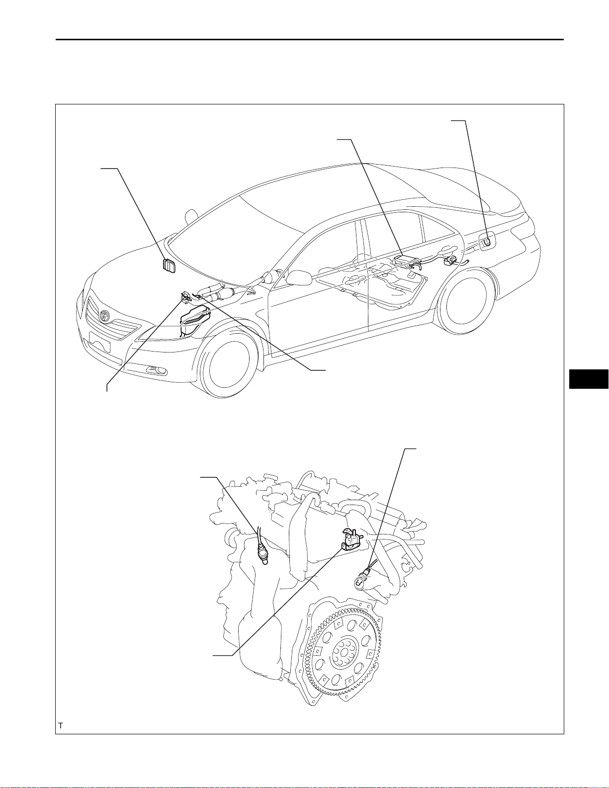
PARTS LOCATION
CANISTER
ECM
EC–1
FUEL TANK CAP
HEATED OXYGEN SENSOR
(BANK 2 SENSOR 2)
AIR FUEL RATIO SENSOR
(BANK 2 SENSOR 1)
VACUUM SWITCHING VALVE
HEATED OXYGEN SENSOR
(BANK 1 SENSOR 2)
AIR FUEL RATIO SENSOR
(BANK 1 SENSOR 1)
EC
A135647E03
EC–2
to Charcoal Canister
2GR-FE EMISSION CONTROL – EMISSION CONTROL SYSTEM
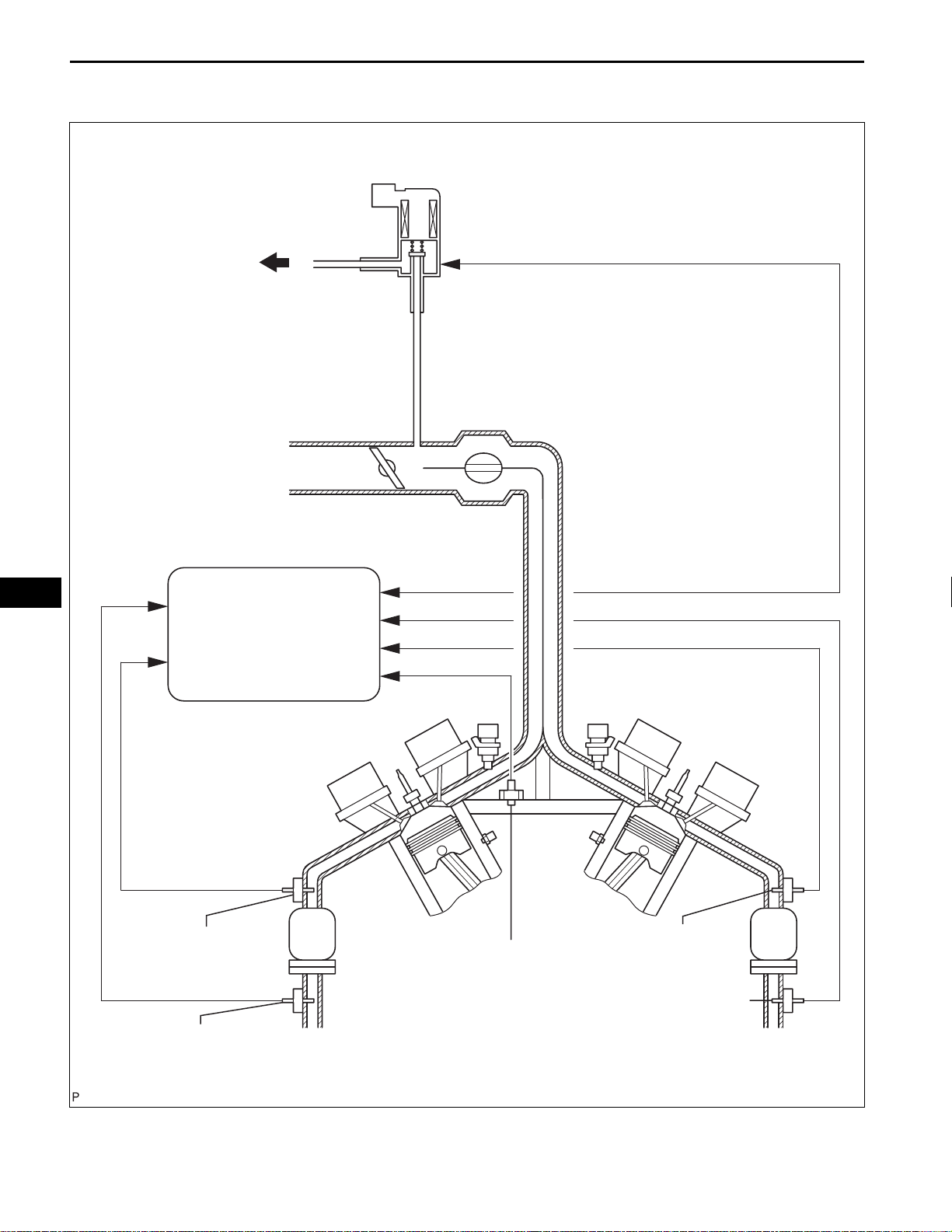
SYSTEM DIAGRAM
VSV for EVAP
EC
ECM
Air Fuel Ratio Sensor
(Bank 1)
Heated Oxygen Sensor
(Bank 1)
Engine Coolant
Temperature Sensor
Air Fuel Ratio Sensor
(Bank 2)
Heated Oxygen Sensor
(Bank 2)
A113656E02
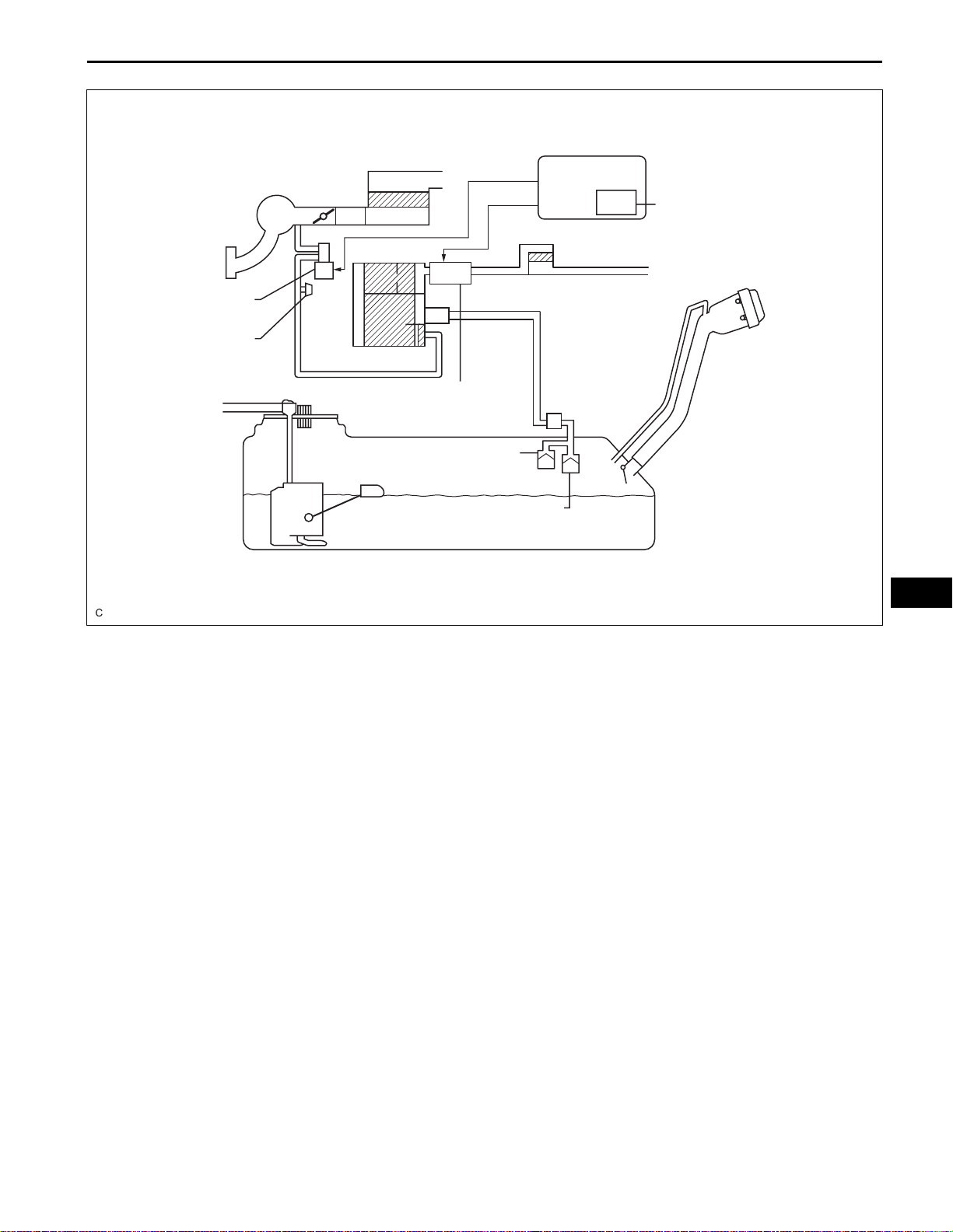
EVAP System Circuit :
2GR-FE EMISSION CONTROL – EMISSION CONTROL SYSTEM
Air Cleaner
ECM
EC–3
Intake Manifold
EVAP VSV
Service Port
Canister
Pump Module
Roll-over Valve
Cut-off Valve
Fuel Tank
Air Filter
Soak Timer
Fuel Cap
A128936E03
EC
EC–4
2GR-FE EMISSION CONTROL – EMISSION CONTROL SYSTEM
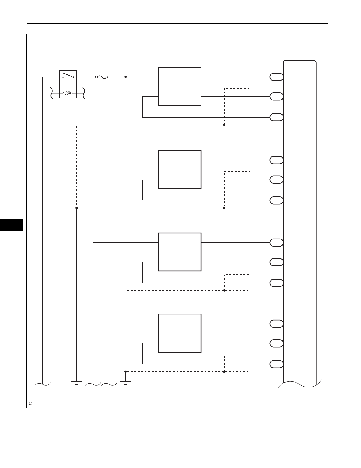
EC
A/F
A/F
C15
Air Fuel Ratio Sensor (Bank 1 Sensor 1)
+B
2
A1A-
4
C35
Air Fuel Ratio Sensor (Bank 2 Sensor 1)
+B
2
A2A-
4
C52
Heated Oxgen Sensor (Bank 1 Sensor 2)
+B
2
OX1B
3
HA1A
A1A+
HA2A
A2A+
E2
HT1B
1
3
1
3
4
1
(*1)
(*1)
(*1)
86
C55
93
C55
116
C55
109
C55
120
C55
119
C55
65
C55
48
C55
88
C55
ECM
HA1A
A1A+
A1A-
HA2A
A2A+
A2A-
EX1B
HT1B
OX1B
C51
Heated Oxgen Sensor (Bank 2 Sensor 2)
2
3
+B
OX2B
E2
HT2B
*1 : Shielded
4
1
(*1)
64
C55
47
C55
87
C55
EX2B
HT2B
OX2B
A135721E02
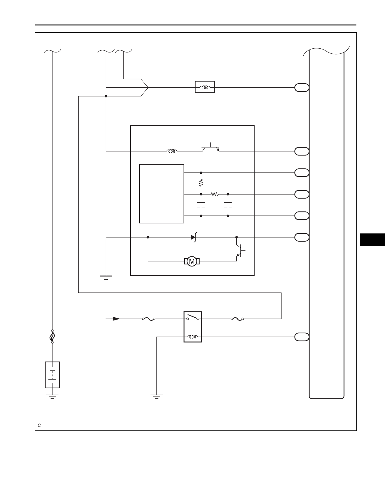
2GR-FE EMISSION CONTROL – EMISSION CONTROL SYSTEM
C6
VSV (Purge)
21
N17
Canister Pump Module
Vent Valve
VLVB
9
Canister
Pressure
Sensor
MGND
Leak Detection Pump
VGND
1
VCC
4
VOUT
3
SGND
2
MTRB
86
108
C55
34
A55
75
C55
77
C55
76
C55
42
A55
PRG
MPMP
VCPP
PPMP
EPPM
VPMP
EC–5
EC
From Battery
FL MAIN
Battery
EFI MAIN
EFI
EFI No. 3
44
A55
MREL
A135722E01
EC
EC–6
2GR-FE EMISSION CONTROL – EMISSION CONTROL SYSTEM
ON-VEHICLE INSPECTION
1. INSPECT FUEL CUT-OFF RPM
(a) Increase the engine speed to at least 3,500 rpm.
(b) Use a sound scope to check for injector operating
sounds.
(c) Check that when the throttle lever is released,
injector operating sounds stop momentarily (at
2,500 rpm) and then resume (at 1,400 rpm).
Standard
Item Specified Condition
Fuel cut off rpm 2,500 rpm
Fuel return rpm 1,400 rpm
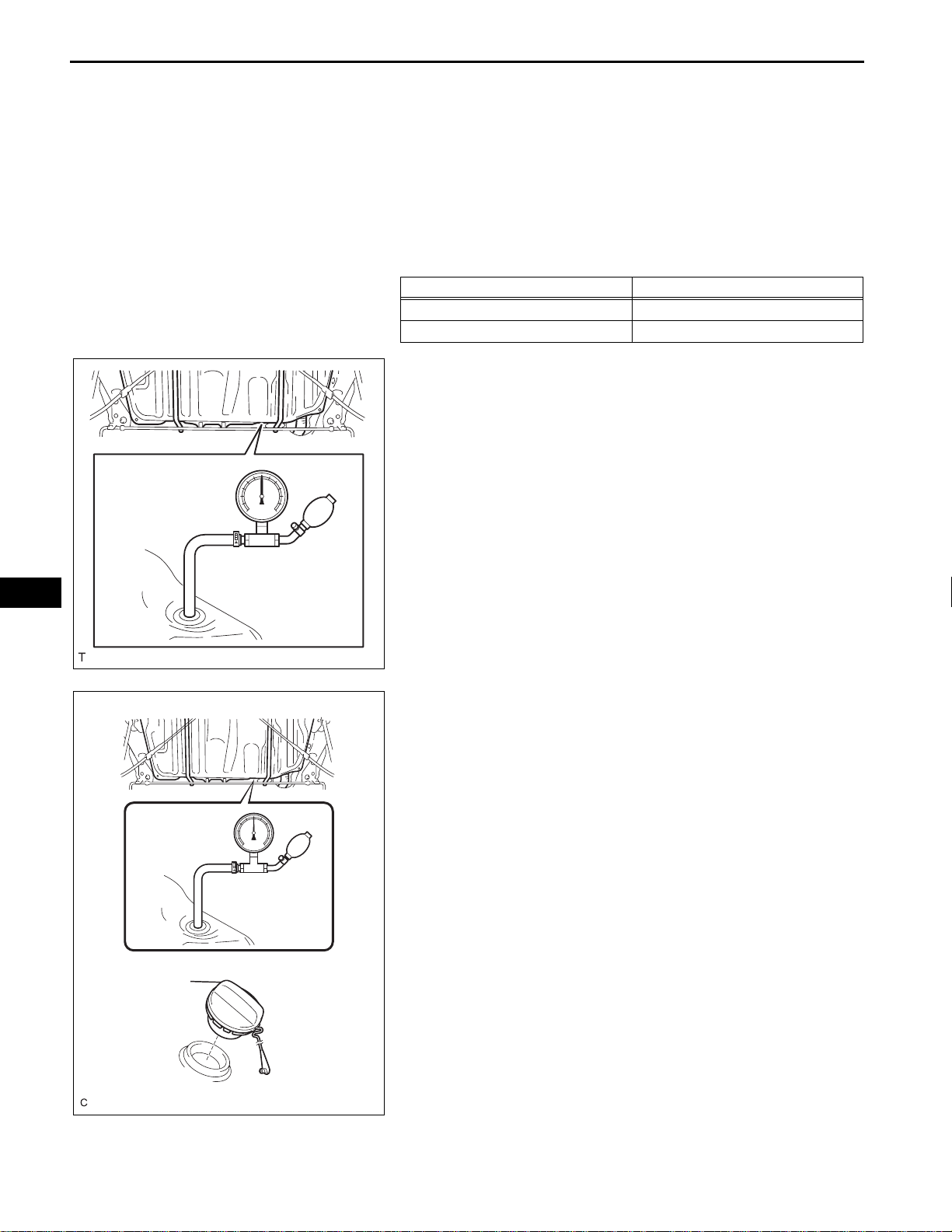
2. CHECK AIR TIGHTNESS IN FUEL TANK AND FILLER
PIPE
(a) Disconnect the vent line hose from the fuel tank.
(b) Connect the pressure gauge to the fuel tank.
(c) Apply pressure to the fuel tank to create an internal
pressure of 4 kPa (41 gf/cm
(d) Check that the internal pressure of the fuel tank is
maintained for 1 minute.
(e) Check the connected portions of each hose and
pipe.
(f) Check the installed parts on the fuel tank.
If any malfunctions, damage or other problems are
found, replace the fuel tank and filler pipe.
(g) Reconnect the vent line hose to the fuel tank.
2
, 0.58 psi).
Fuel Tank Cap
A128092
A126204E01
3. INSPECT FUEL CUT OFF VALVE AND FUEL CHECK
VALVE
(a) Disconnect the vent line hose from the fuel tank.
(b) Connect the pressure gauge to the fuel tank.
(c) Fill the fuel tank with fuel.
(d) Apply pressure of 4 kPa (41 gf/cm
2
, 0.58 psi) to the
vent port of the fuel tank.
HINT:
Check the amount of fuel in the fuel tank. When the
fuel tank is full, the float valve of the fill check valve
is closed and no air can pass through.
(e) Remove the fuel tank cap, and check that the
pressure drops.
If the pressure does not drop, replace the fuel tank
assembly.
(f) Reconnect the vent line hose to the fuel tank.
Air
2GR-FE EMISSION CONTROL – EMISSION CONTROL SYSTEM
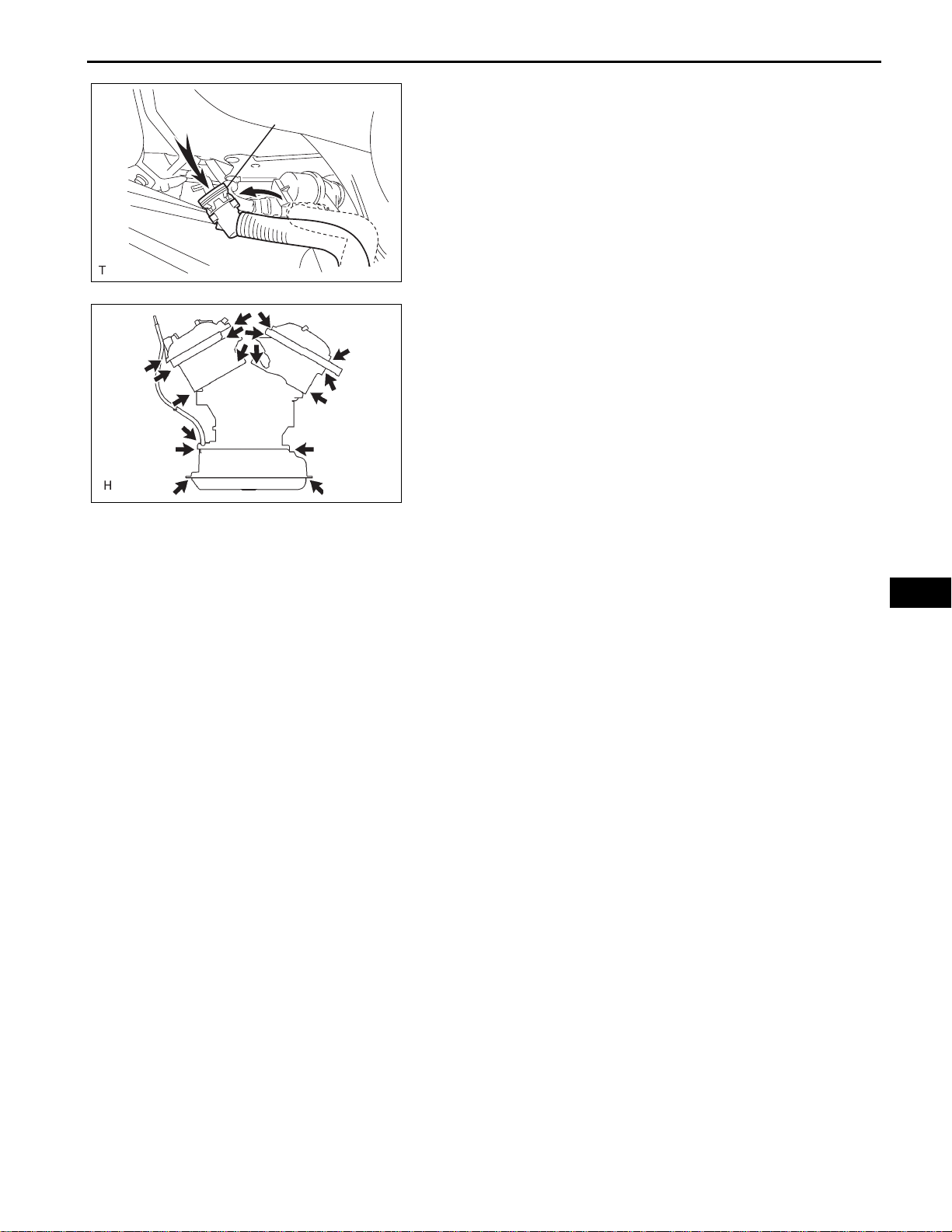
4. CHECK AIR INLET LINE
Air Inlet Hose
(a) Disconnect the air inlet line hose from the charcoal
canister.
(b) Check that air can flow freely into the air inlet line.
If air cannot flow freely into the air inlet line, repair or
replace it.
(c) Reconnect the air inlet line hose to the charcoal
canister.
A128093E02
5. VISUALLY INSPECT HOSES, CONNECTIONS AND
GASKETS
(a) Check for cracks, leaks or damage.
HINT:
Removal or problems with the engine oil dipstick, oil
filler cap, PCV hose and other components may
cause the engine to run improperly. Disconnection,
looseness or cracks in the parts of the air induction
system between the throttle body and cylinder head
A094394
will allow air suction and cause the engine to run
improperly.
If necessary, replace any damaged parts.
EC–7
EC

EC–8
ENGINE2GR-FE EMISSION CONTROL
CANISTER
COMPONENTS
2GR-FE EMISSION CONTROL – CANISTER
EC
CHARCOAL CANISTER ASSEMBLY
39 (398, 29)
N*m (kgf*cm, ft.*lbf)
: Specified torque
A135648E04

Pinch A
2GR-FE EMISSION CONTROL – CANISTER
REMOVAL
1. REMOVE FUEL TANK ASSEMBLY
HINT:
(See page FU-36)
2. REMOVE CHARCOAL CANISTER ASSEMBLY
(a) Disconnect the fuel tank vent hose from the
charcoal canister.
A
(1) Push the connector deep inside.
(2) Pinch portion A.
(3) Pull out the connector.
EC–9
Pinch A
Pinch
Pinch
Push
Push
A
A132954E01
(b) Disconnect the charcoal canister filter sub-assembly
from the charcoal canister.
(1) Push the connector deep inside.
A
(2) Pinch portion A.
(3) Pull out the connector.
(c) Disconnect the vapor pressure sensor connector.
A
(d) Disconnect the wire harness clamp.
(e) Disconnect the purge line hose from the charcoal
canister.
A128095E01
EC
(f) Remove the 2 bolts, clip and charcoal canister.
A128096
A128097
INSPECTION
1. INSPECT CHARCOAL CANISTER ASSEMBLY
(a) Visually check the charcoal canister for cracks or
damage.
If cracks or damage are found, replace the charcoal
canister assembly.

EC–10
Purge Port
Air
2GR-FE EMISSION CONTROL – CANISTER
(b) Check charcoal canister operation.
(1) With the purge port closed, blow 1.67 kPa (17.0
2
gf/cm
, 0.24 psi) of air into the vent port, and
check that air flows from the air inlet port.
If the result is not as specified, replace the
charcoal canister assembly.
EC
Purge Port
Port B
Port A
Vent Port
Air Inlet Port
Air Inlet Port
Vent Port
Purge Port
Air Inlet Port
A128098E01
Air
A128099E02
(2) With the vent port closed, blow 1.10 kPa (11.2
2
gf/cm
, 0.16 psi) of air to the air inlet port, and
check that air flows from the purge port.
If the result is not as specified, replace the
charcoal canister assembly.
(c) Check for air leakage.
(1) Remove the air hose between ports A and B.
(2) Connect the SST (pressure gauge) to the vent
port of the charcoal canister.
SST 09992-00242
(3) While holding port B, with the purge port and
the air inlet port closed and port A open, apply
19.6 kPa (0.2 kgf/cm
2
, 2.81 psi) of pressurized
air into the vent port, then confirm that pressure
is retained for 1 minute.
If the result is not as specified, replace the
charcoal canister assembly.
Vent Port
SST
Air
Pressure Gauge
A128100E02
(d) Check the leak detection pump.
(1) Remove the detection pump from the charcoal
canister.
C
(2) Check that air flows from port A to B and then
C.
If the result is not as specified, replace the
charcoal canister assembly.
A
B
A128108E01

2GR-FE EMISSION CONTROL – CANISTER
EC–11
76
Valve
Closed
(3) Connect the positive (+) lead to terminal 7 and
the negative (-) lead to terminal 6.
(4) Check that the valve is closed.
If the result is not as specified, replace the
charcoal canister assembly.
(5) Install the detection pump.
A128109E01
INSTALLATION
1. INSTALL CHARCOAL CANISTER ASSEMBLY
(a) Install the 2 bolts, clip and charcoal canister.
Torque: 39 N*m (398 kgf*cm, 29 ft.*lbf)
(b) Connect the purge line hose to the charcoal
canister.
(c) Connect the wire harness clamp.
(d) Connect the vapor pressure sensor connector.
(e) Connect the charcoal canister filter sub-assembly to
the charcoal canister.
(f) Connect the fuel tank vent hose to the charcoal
canister.
A128096
2. INSTALL FUEL TANK ASSEMBLY
HINT:
(See page FU-41)
EC

EC–12
ENGINE2GR-FE EMISSION CONTROL
2GR-FE EMISSION CONTROL – VACUUM SWITCHING VALVE (for EVAP)
VACUUM SWITCHING VALVE (for EVAP)
COMPONENTS
V-BANK COVER SUB-ASSEMBLY
VACUUM HOSE
5.0 (51, 44 in.*lbf)
EC
VACUUM HOSE
NO. 1 VACUUM SWITCHING VALVE
N*m (kgf*cm, ft.*lbf)
: Specified torque
A135653E03

2GR-FE EMISSION CONTROL – VACUUM SWITCHING VALVE (for EVAP)
REMOVAL
1. REMOVE V-BANK COVER SUB-ASSEMBLY (See
page EM-23)
2. REMOVE NO. 1 VACUUM SWITCHING VALVE
(a) Disconnect the 2 vacuum hoses and No. 1 vacuum
switching valve connector.
A132952E01
(b) Remove the bolt and No. 1 vacuum switching valve.
EC–13
A132953
INSPECTION
EC
1. INSPECT EVAP VSV
(a) Check the VSV for an open circuit.
(1) Measure the resistance.
2
1
Standard resistance
Tester Connection Specified Condition
1 - 2 23 to 26Ω at 20°C (68°F)
1 - Body ground
2 - Body ground
10 kΩ or higher
If the resistance is not as specified, replace the
VSV assembly.
2
1
A128939E02

EC–14
2GR-FE EMISSION CONTROL – VACUUM SWITCHING VALVE (for EVAP)
(b) Check VSV operation.
(1) Check that air does not flow from the port as
shown in the illustration.
EC
F
E
Air
A128937E01
(2) Apply battery positive voltage across the
terminals.
(3) Check that air flows from the ports.
If the result is not as specified, replace the VSV
F
E
Air
A128938E01
assembly.
INSTALLATION
1. INSTALL NO. 1 VACUUM SWITCHING VALVE
(a) Install the No. 1 vacuum switching valve with the
bolt.
Torque: 5.0 N*m (51 kgf*cm, 44 in.*lbf)
A132953
A132952E01
(b) Disconnect the 2 vacuum hoses and No. 1 vacuum
switching valve connector.
2. INSTALL V-BANK COVER SUB-ASSEMBLY (See
page EM-52)

2GR-FE EMISSION CONTROL – VENTILATION VALVE
ENGINE2GR-FE EMISSION CONTROL
VENTILATION VALVE
COMPONENTS
EC–15
V-BANK COVER SUB-ASSEMBLY
VENTILATION VALVE
27(275, 20)
VENTILATION HOSE
EC
: Specified torque
Precoated partN*m (kgf*cm, ft.*lbf)
A135651E03

EC–16
2GR-FE EMISSION CONTROL – VENTILATION VALVE
REMOVAL
1. REMOVE V-BANK COVER SUB-ASSEMBLY (See
page EM-23)
2. DISCONNECT VENTILATION HOSE
(a) Disconnect the ventilation hose from the ventilation
valve.
A135715E01
3. REMOVE VENTILATION VALVE
(a) Remove the ventilation valve.
EC
Air
Clean Hose
Cylinder Head Side
Clean Hose
Intake Manifold Side
Air
A138519E01
A113429E01
A105281E01
INSPECTION
1. INSPECT VENTILATION VALVE
(a) Install a clean hose to the ventilation valve.
(b) Check the ventilation valve operation.
(1) Blow air into the cylinder head side, and check
that air passes through easily.
NOTICE:
Do not suck air through the valve.
Petroleum substances inside the valve are
hazardous to your health.
(2) Blow air into the intake manifold side, and
check that air passes through with difficulty.
If the result is not as specified, replace the
ventilation valve.
(c) Remove the clean hose from the ventilation valve.

Adhesive
2GR-FE EMISSION CONTROL – VENTILATION VALVE
INSTALLATION
1. INSTALL VENTILATION VALVE
(a) Install the ventilation valve.
(1) Apply adhesive to 2 or 3 threads.
Adhesive:
Part No. 08833-00070, THREE BOND 1324
or equivalent.
A105280E01
(2) Install the ventilation valve.
Torque: 27 N*m (275 kgf*cm, 20 ft.*lbf)
A138519E01
EC–17
A135715E01
2. CONNECT VENTILATION HOSE
(a) Connect the ventilation hose to the ventilation valve.
3. INSTALL V-BANK COVER SUB-ASSEMBLY (See
page EM-52)
EC

EC–18
ENGINE2GR-FE EMISSION CONTROL
2GR-FE EMISSION CONTROL – AIR FUEL RATIO SENSOR
AIR FUEL RATIO SENSOR
COMPONENTS
AIR FUEL RATIO SENSOR
44 (449, 33)
EC
AIR FUEL RATIO SENSOR
N*m (kgf*cm, ft.*lbf)
: Specified torque
44 (449, 33)
A135655E03

2GR-FE EMISSION CONTROL – AIR FUEL RATIO SENSOR
EC–19
Bank 1:
Bank 2:
+B
HT
SST
A128101E02
REMOVAL
1. REMOVE AIR FUEL RATIO SENSOR
(a) Disconnect the 2 air fuel ratio sensor connectors.
(b) Using SST, remove the 2 air fuel ratio sensors from
the front pipe assembly.
SST 09224-00010
INSPECTION
1. INSPECT AIR FUEL RATIO SENSOR
(a) Measure the resistance between terminals 1 (HT)
and 2 (+B).
Standard resistance
EC
Bank 1:
Bank 2:
AF-
Fulcrum Length
AF+
A075325E04
SST
Fulcrum Length
SST
Condition Specified Condition
20 °C (68°F) 1.8 to 3.4 Ω
If the result is not as specified, replace the sensor.
INSTALLATION
1. INSTALL AIR FUEL RATIO SENSOR
(a) Using SST, install the 2 air fuel ratio sensors to the
front pipe assembly.
SST 09224-00010
Torque: 44 N*m (449 kgf*cm, 32 ft.*lbf)
(b) Connect the 2 air fuel ratio sensor connectors.
A128102E03

EC–20
ENGINE2GR-FE EMISSION CONTROL
2GR-FE EMISSION CONTROL – HEATED OXYGEN SENSOR
HEATED OXYGEN SENSOR
COMPONENTS
EC
FRONT EXHAUST PIPE ASSEMBLY
HEATED OXYGEN SENSOR
(BANK 1 SENSOR 2)
62 (632, 46)
GASKET
62 (632, 46)
44 (449, 32)
44 (449, 32)
HEATED OXYGEN SENSOR
(BANK 2 SENSOR 2)
GASKET
56 (571, 41)
GASKET
56 (571, 41)
33 (337, 24)
REAR EXHAUST PIPE NO. 1
SUPPORT BRACKET
FRONT EXHAUST PIPE NO. 1
SUPPORT BRACKET
33 (337, 24)
ENGINE UNDER
COVER RH
N*m (kgf*cm, ft.*lbf)
FRONT EXHAUST PIPE SUPPORT BRACKET
: Specified torque
ENGINE UNDER COVER LH
Non-reusable part
A135657E03

2GR-FE EMISSION CONTROL – HEATED OXYGEN SENSOR
REMOVAL
1. REMOVE ENGINE UNDER COVER LH
2. REMOVE ENGINE UNDER COVER RH
3. REMOVE FRONT EXHAUST PIPE ASSEMBLY (See
page EX-2)
4. REMOVE HEATED OXYGEN SENSOR (for Bank 1)
SST
A135716E01
(a) Using SST, remove the oxygen sensor.
SST 09224-00010
5. REMOVE HEATED OXYGEN SENSOR (for Bank 2)
(a) Using SST, remove the oxygen sensor.
SST 09224-00010
EC–21
+B
E1
SST
EC
A135724E01
INSPECTION
HT
2
1
4
3
OX
A091027E03
1. INSPECT HEATED OXYGEN SENSOR
(a) Measure the resistance between terminals 1 (HT)
and 2 (+B).
Standard resistance
Condition Specified Condition
20°C (68°F) 11 to 16 Ω
If the result is not as specified, replace the sensor.
INSTALLATION
1. INSTALL HEATED OXYGEN SENSOR (for Bank 2)
(a) Using SST, install the heated oxygen sensor.
SST 09224-00010
Torque: 44 N*m (449 kgf*cm, 32 ft.*lbf)
SST
A135725E01

EC–22
2GR-FE EMISSION CONTROL – HEATED OXYGEN SENSOR
2. INSTALL HEATED OXYGEN SENSOR (for Bank 1)
SST
A135717E01
(a) Using SST, install the heated oxygen sensor.
SST 09224-00010
3. INSTALL FRONT EXHAUST PIPE ASSEMBLY (See
page EX-4)
4. INSTALL ENGINE UNDER COVER LH
5. INSTALL ENGINE UNDER COVER RH
EC

2GR-FE EMISSION CONTROL – FUEL TANK CAP
FUEL TANK CAP
INSPECTION
1. REMOVE FUEL TANK CAP ASSEMBLY
(a) Visually check if the cap and gasket are deformed
or damaged.
If necessary, replace the cap.
A126203
EC–23
EC
 Loading...