

Expression
LIGHTING – LIGHTING SYSTEM
LIGHTING SYSTEM
PRECAUTION
1. PRECAUTION FOR USING BATTERY DURING
INSPECTION
(a) While using the battery during inspection, do not
bring the positive and negative tester probes too
close to each other as a short circuit may occur.
2. PRECAUTION FOR HEADLIGHT BULB
REPLACEMENT
(a) If even a thin film of oil is left on the surface of the
halogen light, the bulb may be damaged because
the light will burn at a higher temperature.
(b) Handle any halogen light with great care. Dropping,
hitting or damaging the bulb, in any way, may result
in exploding and shattering because the internal
pressure is high.
(c) Always prepare a new bulb for immediate
replacement. While replacing the bulb, the lens may
attract dust and moisture if removed from the
vehicle for too long.
(d) Always use a bulb of the same wattage for
replacement.
(e) Firmly reinstall the socket after bulb replacement.
The lens may become cloudy or the light cavity may
fill with water through the gaps around the socket.
3. EXPRESSIONS OF IGNITION SWITCH
(a) The type of ignition switch used on this model differs
according to the specifications of the vehicle.
The expressions listed in the table below are used
in this section.
Switch Type Ignition Switch (position) Engine Switch (condition)
Ignition switch off LOCK Off
Ignition switch on (IG) ON On (IG)
Ignition switch on (ACC) ACC On (ACC)
Engine start START Start
LI–1
LI
LI–2
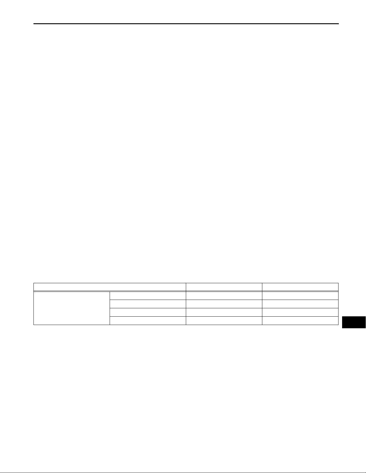
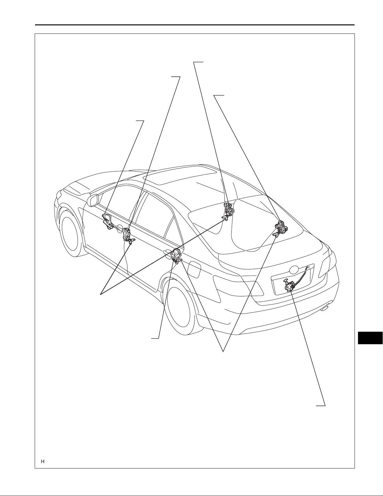
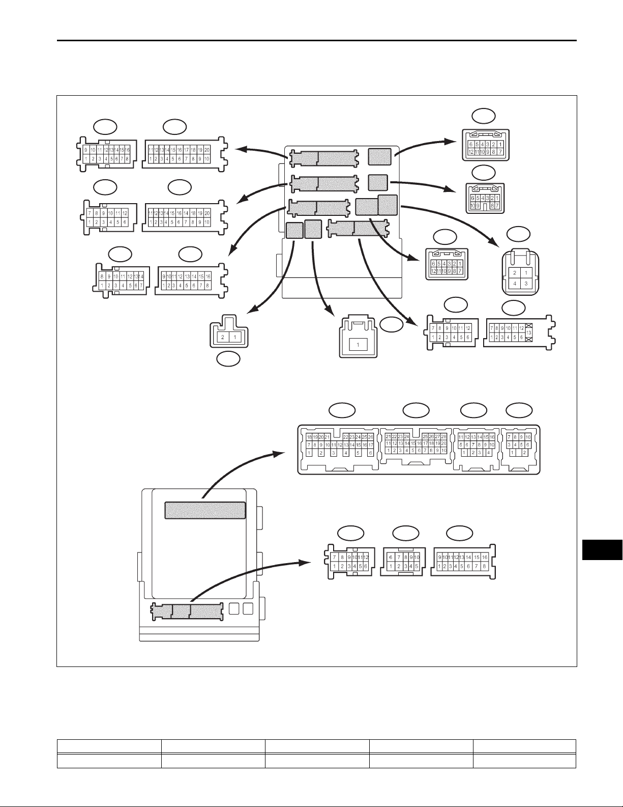
PARTS LOCATION
LIGHTING – LIGHTING SYSTEM
HEADLIGHT ASSEMBLY
- LOW BEAM HEADLIGHT
- HIGH BEAM HEADLIGHT
- FRONT SIDE MARKER LIGHT
- TURN SIGNAL AND PARKING LIGHT
GENERATOR
ENGINE ROOM J/B ASSEMBLY
- POWER DISTRIBUTOR
- H-LP (LL) FUSE
- H-LR (RL) FUSE
- H-LP (LH) FUSE
- H-LP (RH) FUSE
ECM
ENGINE ROOM R/B
- DOME FUSE
- HAZ FUSE
LI
FOG LIGHT ASSEMBLY
PARK / NEUTRAL POSITION SWITCH
(FOR U250E A/T)
PARK / NEUTRAL POSITION SWITCH
(FOR U660E A/T)
BACK-UP LIGHT SWITCH
(FOR M/T)
E121472E01
LIGHTING – LIGHTING SYSTEM
LI–3
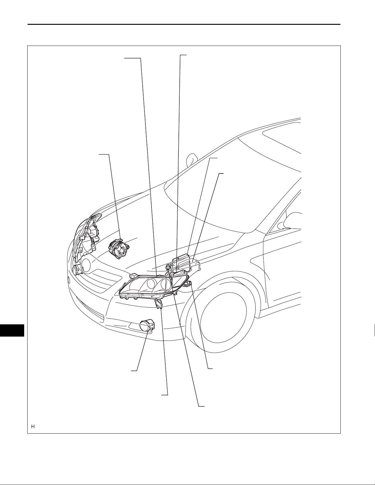
WITHOUT SLIDING ROOF:
PERSONAL LIGHT ASSEMBLY
(OVERHEAD J/B)
- FRONT PERSONAL LIGHTS
- INTERIOR LIGHT
PERSONAL LIGHT ASSEMBLY (OVERHEAD J/B)
- FRONT PERSONAL LIGHTS
REAR ROOM LIGHT ASSEMBLY
- INTERIOR LIGHT
VANITY LIGHT
REAR ROOM LIGHT ASSEMBLY
- REAR PERSONAL LIGHTS
REAR COMBINATION LIGHT ASSEMBLY
- TAIL/STOP AND SIDE MARKER LIGHT
VANITY LIGHT
- TURN SIGNAL LIGHT
REAR LIGHT ASSEMBLY
- BACK-UP LIGHT
- TAILLIGHT
HIGH MOUNTED STOP LIGHT
LI
DOOR COURTESY LIGHT
LUGGAGE ROOM LIGHT
LICENSE PLATE LIGHT
E121473E01
LI–4
LIGHTING – LIGHTING SYSTEM
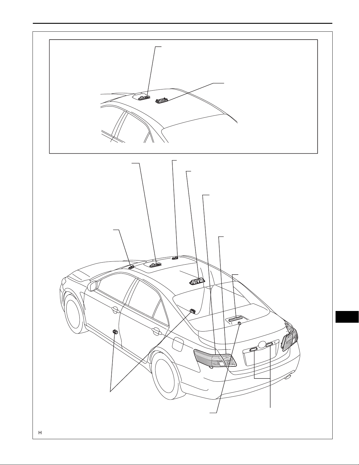
INSTRUMENT PANEL J/B
- MAIN BODY ECU
- IG1 RELAY
- ACC RELAY
- TAIL RELAY
- FOG RELAY
- TAIL FUSE
- AM1 FUSE
- STOP FUSE
- FR FOG FUSE
- GAUGE NO.1 FUSE
HEADLIGHT DIMMER SWITCH
- LIGHT CONTROL SWITCH
- DIMMER SWITCH
- TURN SIGNAL SWITCH
- FOG LIGHT SWITCH
TRANSPONDER KEY AMPRIFIER
IGNITION KEY CYLINDER LIGHT
-
AUTOMATIC LIGHT CONTROL SENSOR
(COMBINATION SWITCH)
GLOVE BOX LIGHT
LI
PARKING BRAKE SWITCH
HAZARD WARNING SWITCH
TURN SIGNAL FLASHER ASSEMBLY
DLC3
STOP LIGHT SWITCH
E121474E01
LIGHTING – LIGHTING SYSTEM
DOOR LOCK ASSEMBLY (FRONT RH)
LI–5
DOOR LOCK ASSEMBLY (FRONT LH)
- DOOR UNLOCK DETECTION SWITCH
MASTER SWITCH ASSEMBLY
- DOOR UNLOCK DETECTION SWITCH
DOOR LOCK ASSEMBLY (REAR RH)
- DOOR UNLOCK DETECTION SWITCH
FRONT DOOR COURTESY SWITCH
DOOR LOCK ASSEMBLY (REAR LH)
- DOOR UNLOCK DETECTION SWITCH
REAR DOOR COURTESY SWITCH
LUGGAGE COMPARTMENT DOOR LOCK ASSEMBLY
-
BACK DOOR COURTESY SWITCH
LI
E121475E01
LI–6
LIGHTING – LIGHTING SYSTEM
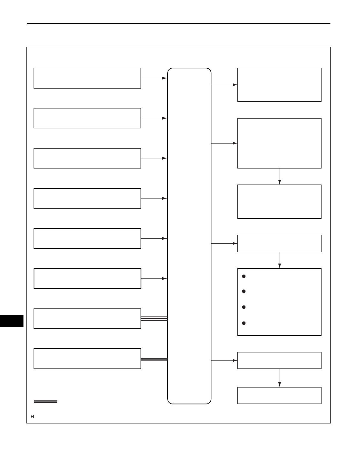
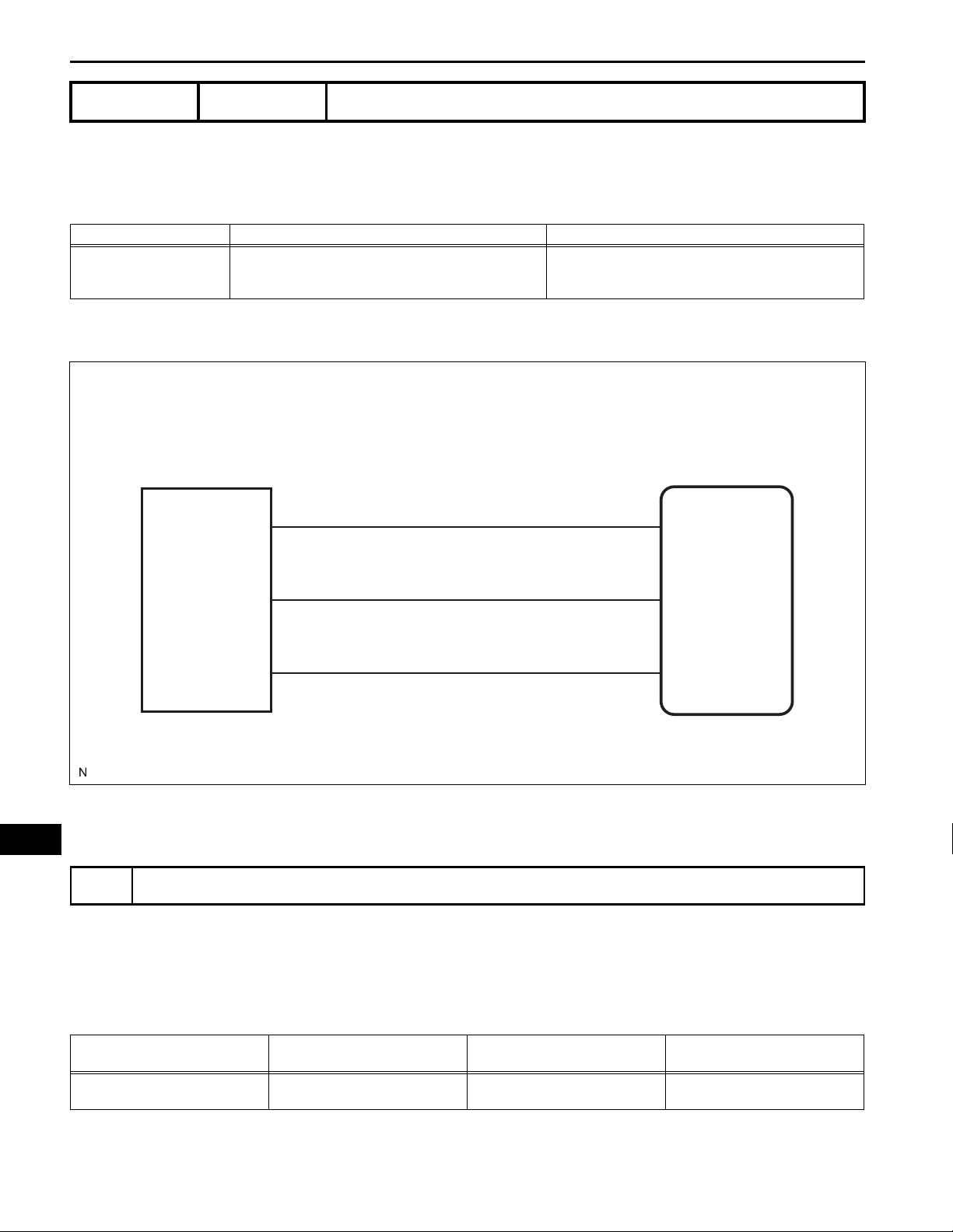
SYSTEM DIAGRAM
Headlight Dimmer Switch Assembly
Automatic Light Control Sensor
Door Courtesy Switches
Door Unlock Detection Switches
Parking Brake Switch
Ignition Key Cylinder Light
Interior Light
Power Distributor
- HEAD Relay
- DRL Relay
Low Beam Headlights
High Beam Headlights
Main Body
ECU
TAIL Relay
LI
Ignition Switch or Engine Switch
ECM
DLC3
: CAN
Taillights
Parking Lights
License Plate Lights
Side Marker Lights
FOG Relay
Front Fog Lights
E121511E01
LIGHTING – LIGHTING SYSTEM
SYSTEM DESCRIPTION
1. MANUAL LIGHT CONTROL SYSTEM
This system functions if the lights such as the headlights
and taillights come on by manual operation of the light
control switch.
(a) The main body ECU controls this system based on
the signals listed below.
Input Output Lights that illuminate
• Taillights
Light control switch TAIL signal Taillight relay drive signal
Light control switch HEAD signal Headlight relay drive signal Low beam headlights
2. AUTOMATIC LIGHT CONTROL SYSTEM
When the light control switch is in the AUTO position, the
automatic light control sensor detects ambient light,
converts it into an electrical signal, and outputs it to the
main body ECU. The main body ECU automatically turns
the headlights and taillights on or off according to the
signal.
(a) The main body ECU controls this system based on
the signals listed below.
• License plate lights
• Side marker lights
• Parking lights
LI–7
Input Output Lights that illuminate
• Light control switch AUTO signal
• Automatic light control sensor signal
Input Output Lights that operate
• Door courtesy switch signal
• Ignition switch or engine switch signal
• Headlight relay drive signal
• Taillight relay drive signal
3. LIGHT AUTO TURN OFF SYSTEM
When the headlights and taillights are on through the
operation of the automatic light control system or through
the light control switch, if the ignition switch is turned off
and all doors are closed, this system continues to
illuminate the headlights and taillights for approximately
30 seconds, and then turns off the headlights and
taillights.
However, if the ignition switch is turned off and all doors
are locked, this system turns off the headlights and
taillights immediately.
(a) The main body ECU controls this system based on
the signals listed below.
• Headlight relay OFF demand
• Taillight relay OFF demand
• DRL relay OFF demand
• FOG light relay OFF demand
• Low beam headlights
• Taillights
• License plate lights
• Side marker lights
• Parking lights
LI
• Low beam headlights
• Taillights, license plate lights, parking
lights, and side marker lights
• High beam headlights
• Front fog lights
LI–8
Items Conditions
Ignition switch or engine switch On (IG)
Engine Running
Light control switch position
Parking brake switch Released (OFF)
Operation Condition
Fade in
Fade out immediately
Illuminate for approximately 15 seconds,
and then fade out
Fade out (Battery saving)
LIGHTING – LIGHTING SYSTEM
OFF, TAIL or AUTO position (if headlight-on control is not being performed by the automatic light
control)
When any of the following conditions is met, the interior light and ignition key cylinder light fade in.
• Any door is opened.
• Any door is unlocked when the ignition switch is off and all doors are closed.
• Ignition switch is turned from on (ACC) to off when all doors are closed.
When either of the following conditions is met, the interior light and ignition key cylinder light fade
out immediately.
• Ignition switch is turned from off to on (ACC or IG) when all doors are closed.
• All doors are locked when the ignition switch is off.
All doors are closed when the ignition switch is off.
When the following conditions are met, the interior light and ignition key cylinder light fade out.
• A key is not in the actuation area (with smart key system).
• A key is not inserted in the ignition key cylinder (without smart key system).
• There are no changes in the condition of the doors for 20 minutes.
4. DAYTIME RUNNING LIGHT SYSTEM
The daytime running light system is designed to
automatically illuminate the headlights (dimmed HI
beams), during the daytime to make the car more visible
to other vehicle.
(a) The main body ECU controls this system.
The daytime running light system starts operating
when all of the following conditions are met:
5. ILLUMINATED ENTRY SYSTEM
When a door is unlocked through a key or transmitter
operation, or if a door is opened, the illuminated entry
system turns on the interior light and the ignition key
cylinder light.
(a) The main body ECU controls this system. The
operation and condition of the illuminated entry
system are described below.
LI
Power Distributor (Engine Room J/B)
LIGHTING – LIGHTING SYSTEM
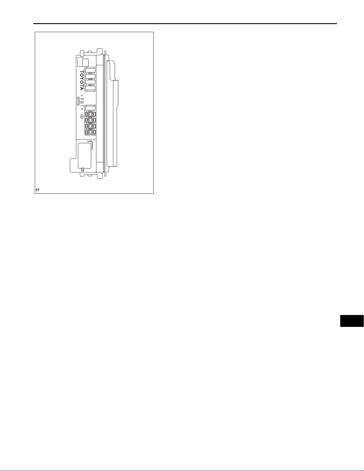
6. POWER DISTRIBUTOR
(a) The power distributor (engine room J/B assembly) is
installed in the engine room R/B.
(b) The HEAD relay and DRL relay are installed in the
power distributor (engine room J/B assembly).
(c) When a short circuit occurs between the power
distributor (engine room J/B assembly) and high
beam headlight bulbs, a fail-safe function operates.
(d) When the fail-safe function operates, the power
distributor stops the operation of the DRL relay.
E121471E02
LI–9
LI
LI–10
1
NEXT
2
NEXT
3
LIGHTING – LIGHTING SYSTEM
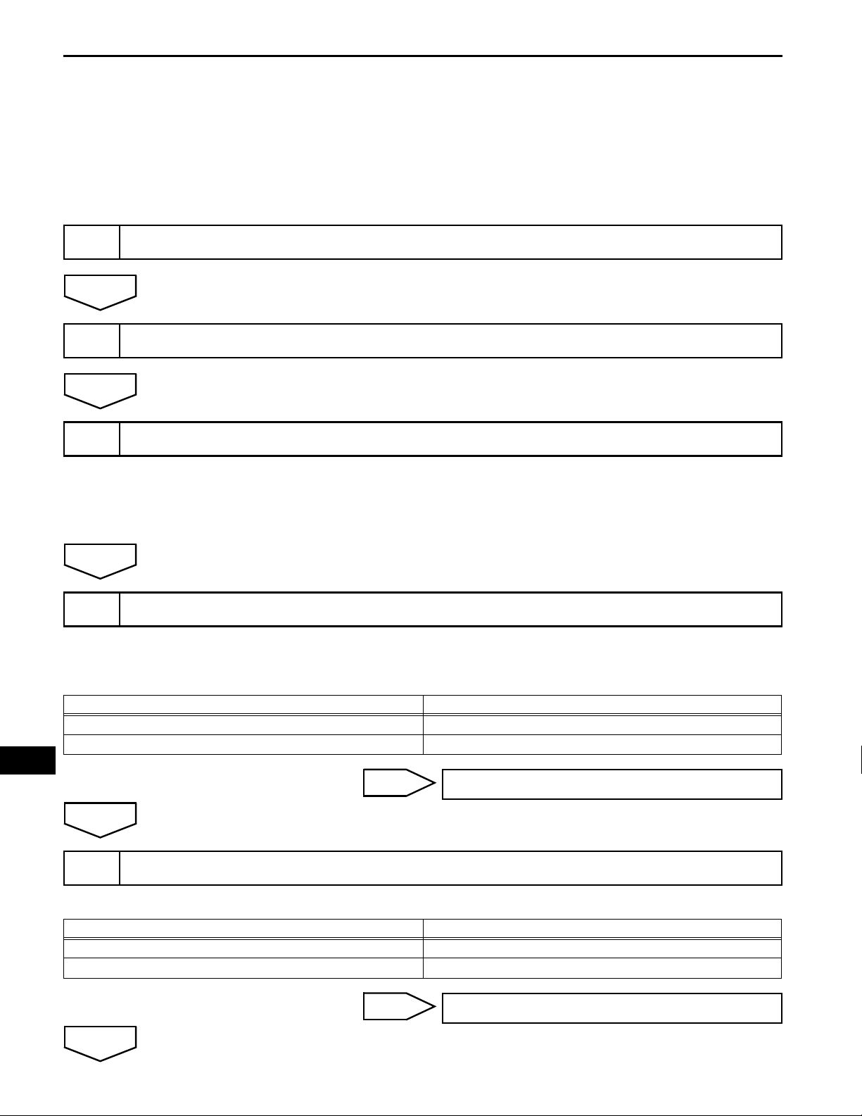
HOW TO PROCEED WITH
TROUBLESHOOTING
HINT:
• Use the following procedures to troubleshoot the lighting
system.
• *: Use the intelligent tester.
VEHICLE BROUGHT TO WORKSHOP
CUSTOMER PROBLEM ANALYSIS CHECK AND SYMPTOM CHECK
INSPECT BATTERY VOLTAGE
Standard voltage:
11 to 14 V
If the voltage is below 11 V, recharge or replace the battery
before proceeding.
NEXT
INSPECT CAN COMMUNICATION SYSTEM*
4
(a) Use the intelligent tester to check if the CAN
communication system is functioning normally.
Result
Result Proceed to
CAN communication system DTC is not output A
CAN communication system DTC is output B
LI
A
CHECK FOR DTC*
5
B
Go to step 8
Result
Result Proceed to
DTC is not output A
DTC is output B
B
A
Go to step 8
LIGHTING – LIGHTING SYSTEM
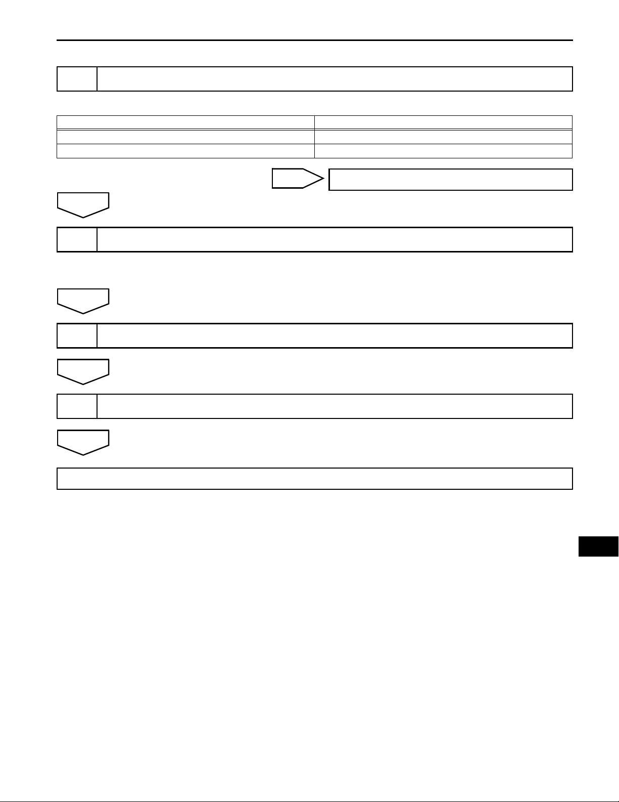
PROBLEM SYMPTOMS TABLE
6
Result
Result Proceed to
Fault is not listed in problem symptoms table A
Fault is listed in problem symptoms table B
LI–11
A
7
NEXT
8
NEXT
9
NEXT
B
OVERALL ANALYSIS AND TROUBLESHOOTING*
(a) Data List / Active Test (See page LI-21)
(b) Terminals of ECU (See page LI-16)
ADJUST, REPAIR OR REPLACE
CONFIRMATION TEST
Go to step 8
END
LI
LI–12
ILLUMINATED ENTRY:
Display Default Contents Setting
LIGHTING TIME 15 s
I/L ON / UNLOCK ON
I/L ON / ACC OFF ON
LIGHTING – LIGHTING SYSTEM
CUSTOMIZE PARAMETERS
HINT:
The followings are the possible items to be customized.
NOTICE:
• Before attempting to customize vehicle settings,
confirm whether it is possible to make the change that
the customer has requested.
• Be sure to record the current value before
customizing.
• In case of performing the troubleshooting, pay
attention because there is a possibility that the
function has been disabled by customizing. (Example:
In case of the symptom in which "The wireless
operation does not function", check that the wireless
operation has not been disabled by customizing, then
perform the troubleshooting.)
Changes the lighting time of the
interior light and ignition key
cylinder light.
Lights up the interior light and
ignition key cylinder light when a
door is unlocked.
Lights up the interior light and
ignition key cylinder light when
the ignition switch is turned from
on (ACC) to off
7.5 s / 15 s / 30 s
ON / OFF
ON / OFF
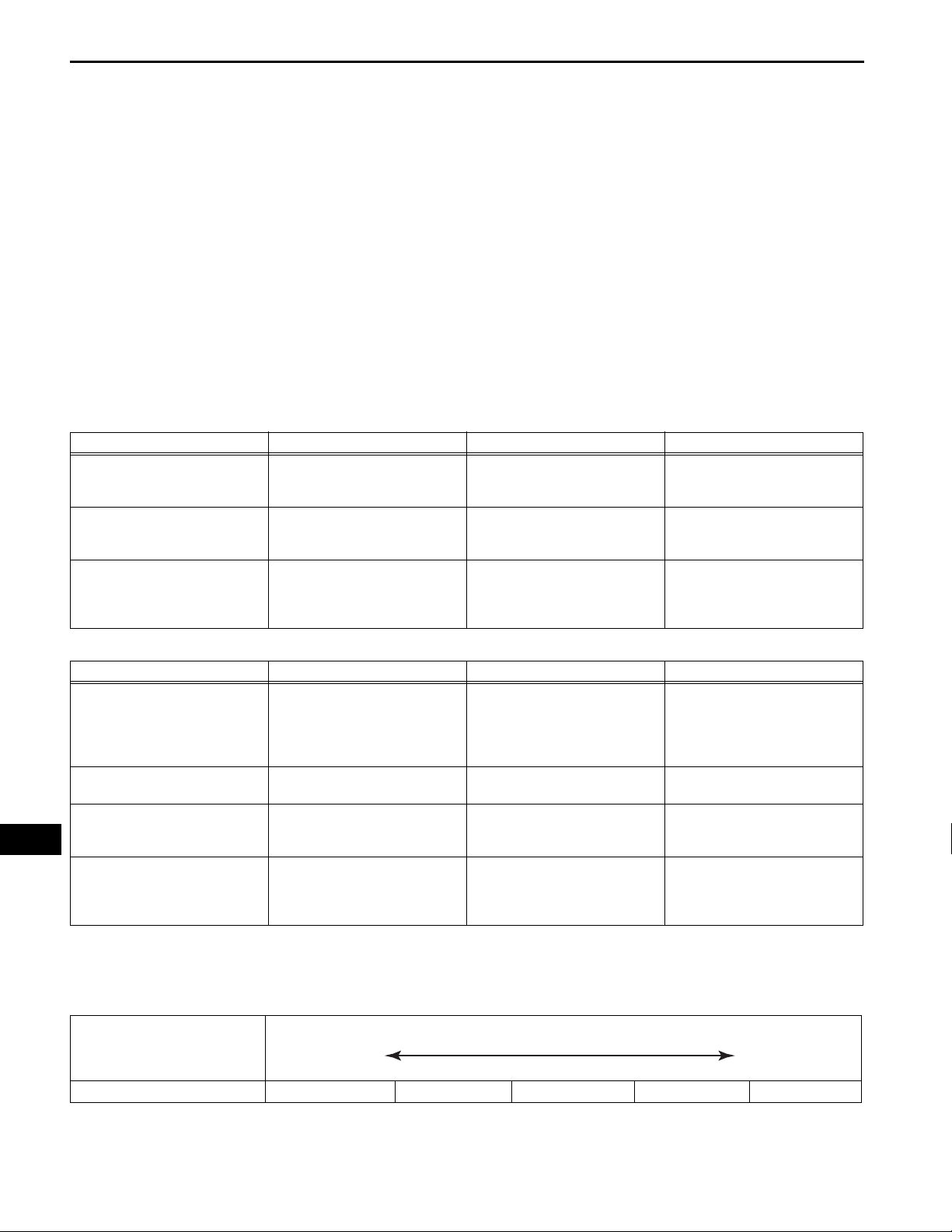
LIGHT CONTROL:
LIGHT OFF DELAY 30 s
DISP EX ON SEN NORMAL
LI
DISP EX OFF SEN NORMAL
Illustration *1
Ambient Brightness Level
Display Default Contents Setting
Keeps the headlights on for a
certain period of time after turning
OFF / 30 s / 60 s / 90 s
LIGHT 2 / LIGHT 1 / NORMAL /
DARK 1 / DARK 2
LIGHT 2 / LIGHT 1 / NORMAL /
DARK 1 / DARK 2
LIGHT 2 / LIGHT 1 / NORMAL /
DARK 1 / DARK 2
SENSITIVITY NORMAL
the ignition switch off and closing
all the doors with the headlights
on.
Adjusts the sensitivity of the
automatic light control system. *1
Changes the ambient brightness
level required to dim the clock
display illumination, etc. *1
Changes the ambient brightness
level required to cancel the
dimming of the clock display
illumination, etc.
HINT:
Sensitivity adjustment can hardly be confirmed. Check by
driving the customer's vehicle.
Dark Bright
Setting DARK2 DARK1 NORMAL LIGHT1 LIGHT2
LIGHTING – LIGHTING SYSTEM
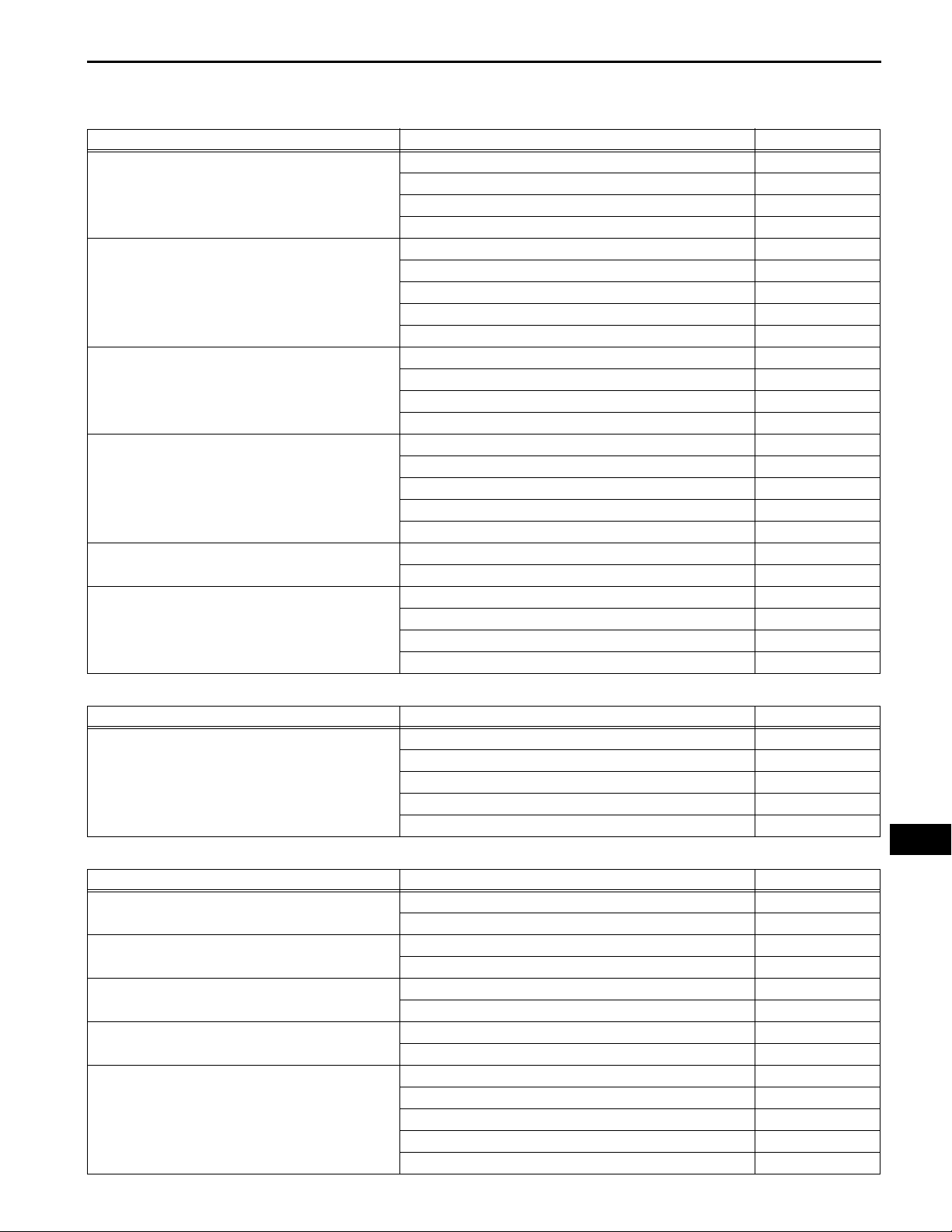
1. Headlight system:
Symptom Suspected area See page
One side LO-beam headlight does not illuminate
Both left and right LO-beam headlights do not
illuminate
One side HI-beam headlight does not illuminate
Both left and right HI-beam headlights do not illuminate
"Flash" headlights do not illuminate
LO-beam headlights or HI-beam headlights do not go
off
LI–13
PROBLEM SYMPTOMS TABLE
1. H-LP RL fuse or H-LP LL fuse -
2. Bulb -
3. Harness or connector -
4. Power distributor (Engine room J/B) -
1. H-LP RL fuse and H-LP LL fuse -
2. Bulb -
3. Light control switch circuit LI-48
4. Headlight relay circuit LI-35
5. Main body ECU (Instrument panel J/B) -
1. H-LP RH fuse or H-LP LH fuse -
2. Bulb -
3. Harness or connector -
4. Power distributor (Engine room J/B) -
1. H-LP RH fuse and H-LP LH fuse -
2. Bulb -
3. Light control switch circuit LI-48
4. Headlight (HI-BEAM) circuit LI-39
5. Main body ECU (Instrument panel J/B) -
1. Light control switch circuit LI-48
2. Main body ECU (Instrument panel J/B) -
1. Headlight dimmer switch assembly LI-120
2. Power distributor (Engine room J/B) -
3. Harness or connector -
4. Main body ECU (Instrument panel J/B) -
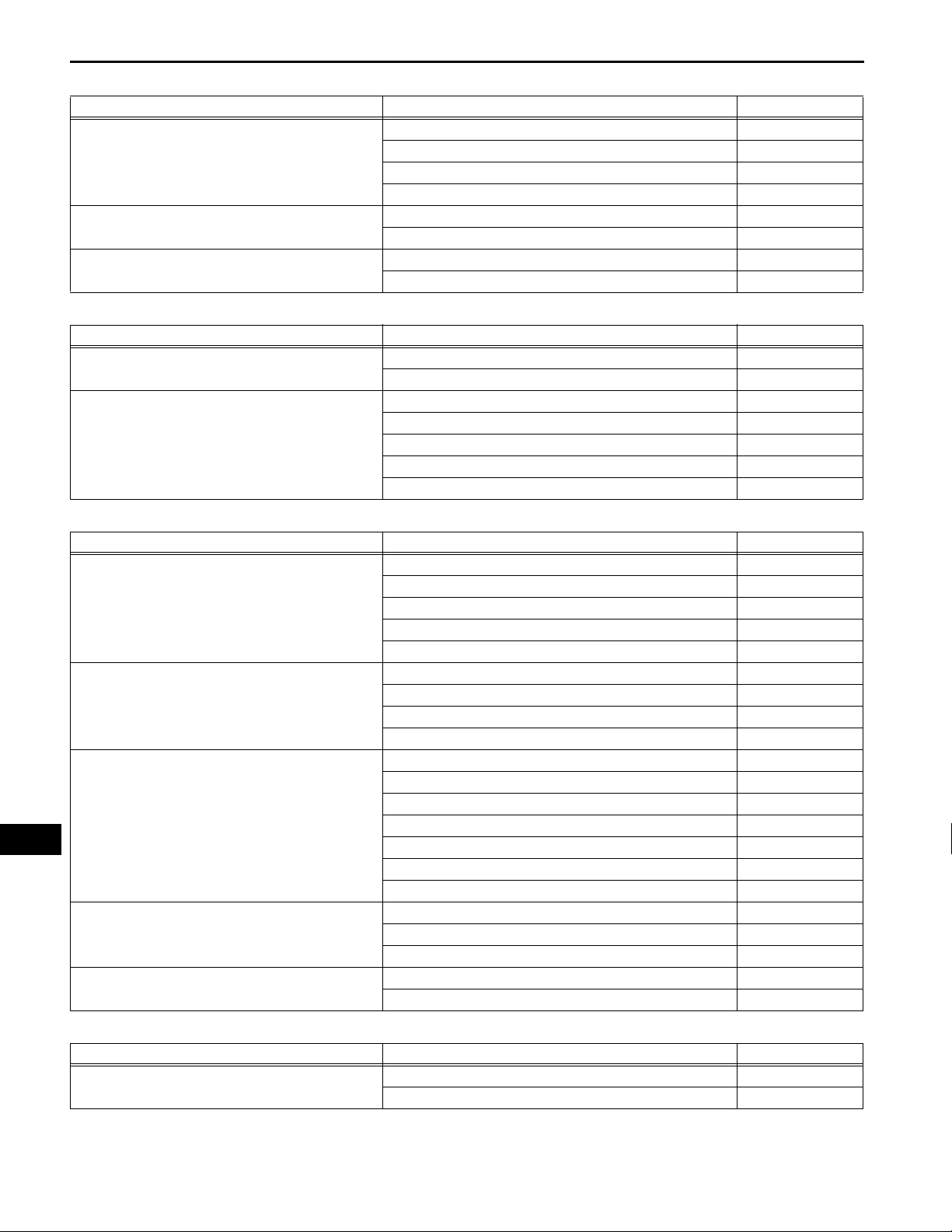
2. Daytime running light system:
Symptom Suspected area See page
Day time running light system does not operate
3. Taillight system:
Symptom Suspected area See page
Front parking light does not illuminate
Rear taillight does not illuminate
License plate light does not illuminate
Front side marker light does not illuminate
Taillight system does not operate (Taillights, front side
marker lights, parking lights, and license plate lights do
not illuminate)
1. Light control switch circuit LI-48
2. Parking brake switch circuit LI-61
3. Power distributor (Engine room J/B) -
4. Main body ECU (Instrument panel J/B) -
5. ECM -
LI
1. Bulb -
2. Harness or connector -
1. Bulb -
2. Harness or connector -
1. Bulb -
2. Harness or connector -
1. Bulb -
2. Harness or connector -
1. TAIL fuse -
2. Taillight relay LI-141
3. Light control switch circuit LI-48
4. Taillight relay circuit LI-65
5. Main body ECU (Instrument panel J/B) -
LI–14
LIGHTING – LIGHTING SYSTEM
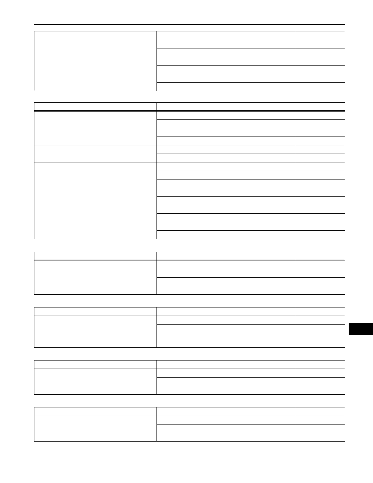
4. Stop light system:
Symptom Suspected area See page
Stop light system does not operate
One side stop light does not illuminate
Hi-mounted stop light does not illuminate
5. Front fog light system:
Symptom Suspected area See page
One side fog light does not illuminate
Both left and right fog lights do not illuminate (Taillight
system is normal)
1. Bulb -
2. Stop fuse -
3. Stop light switch LI-125
4. Harness or connector -
1. Bulb -
2. Harness or connector -
1. Bulb -
2. Harness or connector -
1. Bulb -
2. Harness or connector -
1. FR FOG fuse -
2. FR FOG relay LI-142
3. Light control switch circuit LI-48
4. Front fog light circuit LI-44
5. Main body ECU (Instrument panel J/B) -
6. Turn signal and hazard warning system:
Symptom Suspected area See page
Hazard warning lights do not operate (Turn signal
lights are normal)
Turn signal lights do not operate (Hazard warning
lights are normal)
"Hazard" and "Turn" do not operate
LI
Turn signal lights do not operate in one direction
Only one bulb does not operate
1. HAZ fuse -
2. Hazard warning signal switch LI-123
3. Clock assembly OT-4
4. Turn signal flasher assembly LI-138
5. Harness or connector -
1. GAUGE No. 1 fuse -
2. Headlight dimmer switch assembly (Turn signal switch) LI-120
3. Turn signal flasher assembly LI-138
4. Harness or connector -
1. HAZ fuse and GAUGE No. 1 fuse -
2. Bulb -
3. Turn signal flasher assembly LI-138
4. Hazard warning signal switch LI-123
5. Headlight dimmer switch assembly (Turn signal switch) LI-120
6. Clock assembly OT-4
7. Harness or connector -
1. Headlight dimmer switch assembly (Turn signal switch) LI-120
2. Turn signal flasher assembly LI-138
3. Harness or connector -
1. Bulb -
2. Harness or connector -
7. Buck-up light system:
Symptom Suspected area See page
One side back-up light does not illuminate
1. Bulb -
2. Harness or connector -
Symptom Suspected area See page
Both left and right back-up lights do not illuminate
8. Illuminated entry system:
Symptom Suspected area See page
Only interior light does not illuminate
Only ignition key cylinder light does not illuminate
Interior light and ignition key cylinder light do not
operate normally
LIGHTING – LIGHTING SYSTEM
1. Bulb -
2. GAUGE No. 1 fuse -
3. Buck-up light switch (for M/T) LI-127
4. Park/Neutral position switch (for U250E A/T) AX-129
5. Park/Neutral position switch (for U660E A/T) AX-175
6. Harness or connector -
1. Bulb -
2. Personal light assembly (with sliding roof) LI-105
3. Rear room light assembly (without sliding roof) LI-108
4. Harness or connector -
1. Transponder key amplifier (Ignition key cylinder light) LI-113
2. Harness or connector -
1. DOME fuse -
2. Personal light assembly LI-105
3. Rear room light assembly LI-108
4. Transponder key amplifier LI-113
5. Door courtesy switch circuit LI-52
6. Door lock position switch circuit LI-55
7. Ignition switch circuit LI-28
8. Interior light circuit LI-57
9. Main body ECU (Instrument panel J/B) -
LI–15
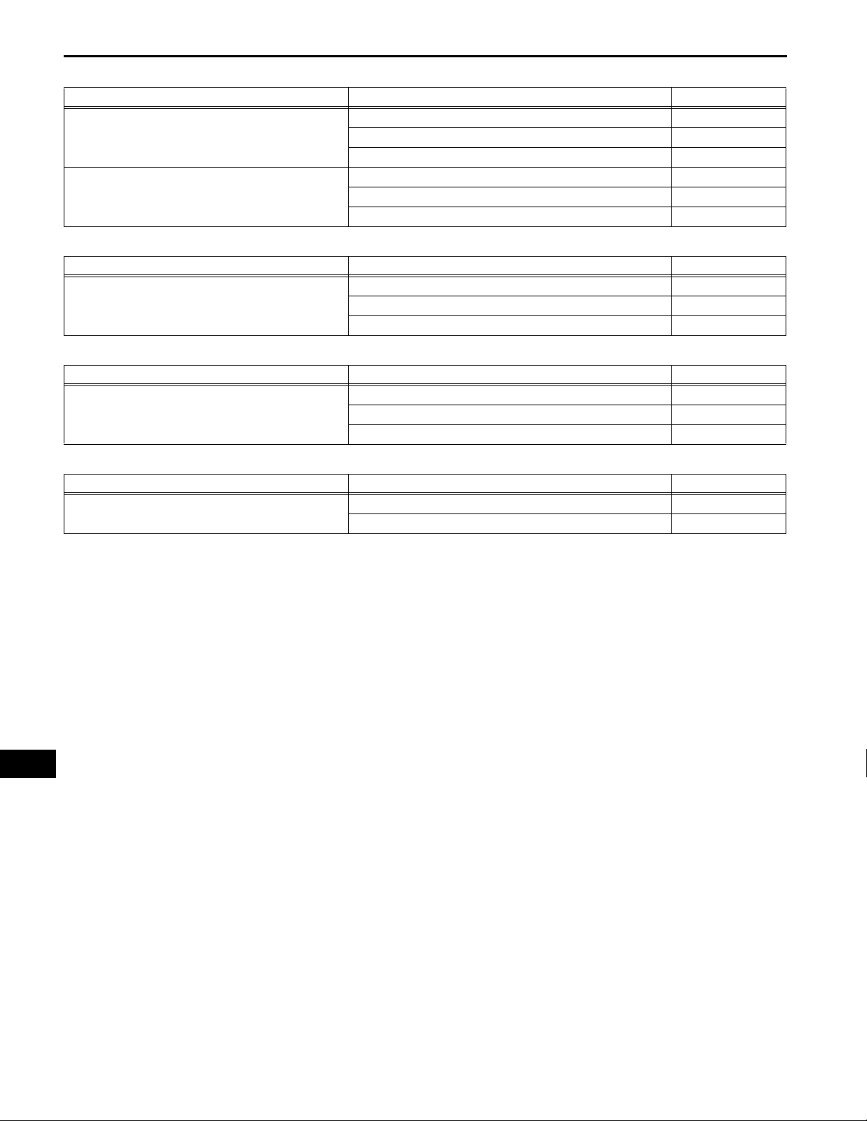
9. Vanity light system:
Symptom Suspected area See page
Vanity light does not illuminate
10. Luggage compartment light system:
Symptom Suspected area See page
Luggage compartment light does not illuminate
11. Glove box light system:
Symptom Suspected area See page
Glove box light does not illuminate
12. Door courtesy light system:
Symptom Suspected area See page
Door courtesy light does not illuminate
1. Bulb -
2. Vanity light assembly LI-116
3. Visor assembly (Vanity light switch) -
4. Harness or connector -
1. Luggage compartment light LI-111
2. Luggage compartment door lock assembly (Door courtesy
switch)
3. Harness or connector -
1. Bulb -
2. Glove box light assembly LI-115
3. Harness or connector -
1. Door courtesy light LI-109
2. Front door courtesy switch LI-129
3. Harness or connector -
LI-132
LI
LI–16
13. Personal light system:
Symptom Suspected area See page
Front personal lights do not illuminate
Rear personal lights do not illuminate
14. Automatic light control system:
Symptom Suspected area See page
Automatic light control system does not operate
normally
15. Light auto turn off system:
Symptom Suspected area See page
Light auto turn off system does not operate normally
LIGHTING – LIGHTING SYSTEM
1. Bulb -
2. Personal light assembly LI-105
3. Harness or connector -
1. Bulb -
2. Rear room light assembly LI-108
3. Harness or connector -
1. Light control switch circuit LI-48
2. Automatic light control sensor circuit LI-23
3. Main body ECU (Instrument panel J/B) -
1. Light control switch circuit LI-48
2. Door courtesy switch circuit LI-52
3. Main body ECU (Instrument panel J/B) -
16. Battery saving system:
Symptom Suspected area See page
Battery saving function does not operate
LI
1. Door courtesy switch circuit LI-52
2. Main body ECU (Instrument panel J/B) -
LIGHTING – LIGHTING SYSTEM
TERMINALS OF ECU
1. CHECK MAIN BODY ECU (INSTRUMENT PANEL J/B)
LI–17
Front Side:
IL IF
IMIK
IC ID
IB
IA
IR
IP
IJ
IE
IN
IO
Back Side:
E7
IG II IH
E6 E8 E9
(a) Disconnect the IA, ID, IF and IM J/B connectors.
(b) Measure the voltage and resistance between the
specified terminals of the wire harness side
connectors and body ground.
Standard voltage
Symbols Wiring Color Terminal Description Condition Specified Condition
IA-1 - Body ground B - Body ground Battery power supply Always 10 to 14 V
LI
E111961E05
LI–18
Symbols Wiring Color Terminal Description Condition Specified Condition
ALTB (ID-16) - Body
ground
Standard resistance
Symbols Wiring Color Terminal Description Condition Specified Condition
GND1 (IF-10) - Body
ground
GND2 (IM-9) - Body
ground
Standard resistance
Symbols Wiring Color Terminal Description Condition Specified Condition
CLTE (E6-18) - Body
ground
LIGHTING – LIGHTING SYSTEM
W - Body ground Generator power supply Always 10 to 14 V
W-B - Body ground Ground Always Below 1 Ω
W-B - Body ground Ground Always Below 1 Ω
If the result is not as specified, there may be a
malfunction on the wire harness side.
(c) Reconnect the IA, ID, IF, and IM J/B connectors.
(d) Measure the resistance and voltage between the
specified terminals of the J/B connectors and body
ground.
BR - Body ground
Automatic light control
ground
Always Below 1 Ω
Standard voltage
Symbols Wiring Color Terminal Description Condition Specified Condition
PKB (IC-14) - Body
ground (*3)
HRLY (ID-3) - Body
ground
DRL (ID-9) - Body
ground
HU (IG-5) - Body ground LG - Body ground
ILE (II-10) - Body ground
(*2)
LI
PKB (IM-2) - Body
ground (*4)
LCTY (IO-7) - Body
ground
LSR (IP-5) - Body ground
(*2)
LSWL (IP-5) - Body
ground (*2)
HEAD (E6-17) - Body
ground
L - Body ground
P - Body ground
V - Body ground
BR - Body ground
Y - Body ground
LG - Body ground
GR - Body ground
GR - Body ground
P - Body ground
Parking brake switch
input
Headlight relay drive
output
High beam headlights
drive output
Dimmer switch HIGH
input
Interior light and igniti on
key cylinder light drive
output
Parking brake switch
input
Rear left door courtesy
switch input
Rear left door lock
position switch input
Rear left door lock
position switch input
Light control switch
HEAD input
Parking brake switch ON Below 1 V
Parking brake switch
OFF
Light control switch in
HEAD
Light control switch not
in HEAD
Dimmer switch in HIGH
or HIGH FLASH
Dimmer switch in LOW 10 to 14 V
Dimmer switch in HIGH
or HIGH FLASH
Dimmer switch in LOW Below 1 V
Interior light and igni tion
key cylinder light ON
Interior light and igni tion
key cylinder light OFF
Parking brake switch ON Below 1 V
Parking brake switch
OFF (Released)
Rear left door open Below 1 V
Rear left door closed 10 to 14 V
Rear left door locked 10 to 14 V
Rear left door unlocked Below 1 V
Rear left door locked 10 to 14 V
Rear left door unlocked Below 1 V
Light control switch in
HEAD
Light control switch not
in HEAD
10 to 14 V
Below 1 V
10 to 14 V
Below 1 V
10 to 14 V
Below 1 V
10 to 14 V
10 to 14 V
Below 1 V
10 to 14 V
Symbols Wiring Color Terminal Description Condition Specified Condition
CLTS (E6-19) - Body
ground
CLTB (E6-20) - Body
ground
PCTY (E6-21) - Body
ground
LGCY (E6-25) - Body
ground
LSWP (E6-27) - Body
ground
FFOG (E6-28) - Body
ground
LSWR (E6-5) - Body
ground (*1)
RCTY (E6-5) - Body
ground (*2)
RCTY (E6-7) - Body
ground (*1)
HF (E7-13) - Body
ground
SSW2 (E7-16) - Body
ground (*1)
SSW1 (E7-17) - Body
ground (*1)
A (E7-21) - Body ground G - Body ground
ACCD (E7-22) - Body
ground (*1)
TAIL (E7-23) - Body
ground
DCTY (E7-24) - Body
ground
IG1D (E7-3) - Body
ground (*1)
G - Body ground
B - Body ground
Y - Body ground
W - Body ground
LG - Body ground
V - Body ground
V - Body ground
GR - Body ground
GR - Body ground
R - Body ground
V - Body ground Engine switch input
L - Body ground Engine switch input
W - Body ground
B - Body ground
L - Body ground
P - Body ground
LIGHTING – LIGHTING SYSTEM
Automatic light control
sensor signal input
Automatic light control
sensor power supply
output
Passenger side door
courtesy switch input
Luggage courtesy
switch input
Passenger side door
lock position switch
input
Front fog light switch
input
Rear right door lock
position switch input
Rear right door courtesy
switch input
Rear right door courtesy
switch input
Dimmer switch HIGH
FLASH signal input
Light control switch
AUTO signal input
Accessory relay drive
output
Light control switch
TAIL signal input
Driver side door
courtesy switch input
Ignition 1 relay drive
output
Ignition switch off Below 1 V
Automatic light control
system operates
Ignition switch off Below 1 V
Ignition switch on (IG)
and light control switch
in AUTO
Passenger side door
open
Passenger side door
closed
Luggage compartment
door open
Luggage compartment
door closed
Passenger side door
locked
Passenger side door
unlocked
Front fog light switch
ON
Front fog light switch
OFF
Rear right door locked 10 to 14 V
Rear right door
unlocked
Rear right door open Below 1 V
Rear right door closed 10 to 14 V
Rear right door open Below 1 V
Rear right door closed 10 to 14 V
Dimmer switch in HIGH
FLASH position
Dimmer switch not in
HIGH FLASH position
Engine switch not
pushed
Engine switch pushed Below 1 V
Engine switch not
pushed
Engine switch pushed Below 1 V
Light control switch in
AUTO
Light control switch not
in AUTO
Ignition switch on (ACC) Below 1 V
Ignition switch off 10 to 14 V
Light control switch in
TAIL or HEAD
Light control switch in
neither TAIL nor HEAD
Driver side door open Below 1 V
Driver side door closed 10 to 14 V
Ignition switch on (IG) Below 1 V
Ignition switch off 10 to 14 V
LI–19
Pulse generation
(See waveform 1)
10 to 14 V
Below 1 V
10 to 14 V
Below 1 V
10 to 14 V
10 to 14 V
Below 1 V
Below 1 V
10 to 14 V
Below 1 V
Below 1 V
10 to 14 V
10 to 14 V
10 to 14 V
LI
Below 1 V
10 to 14 V
Below 1 V
10 to 14 V
LI–20
Symbols Wiring Color Terminal Description Condition Specified Condition
FFGO (E7-4) - Body
ground
LSWD (E7-9) - Body
ground
CANH (E8-5) - Body
ground
CANL (E8-6) - Body
ground
R - Body ground
L - Body ground
R - Body ground
W - Body ground
LIGHTING – LIGHTING SYSTEM
Light control switch in
Front fog light relay
drive output
Driver side door lock
position switch input
Control system CAN
communication
Control system CAN
communication
HEAD and front fog light
switch ON
Front fog light switch
OFF
Driver side door locked 10 to 14 V
Driver side door
unlocked
Ignition switch on (IG) Pulse generation
Ignition switch off Below 1 V
Ignition switch on (IG) Pulse generation
Ignition switch off Below 1 V
If the result is not as specified, the main body ECU
(Instrument panel J/B) may have a malfunction.
HINT:
*1: with smart key system
*2: without smart key system
*3: Pedal type parking brake
*4: Lever type parking brake
Below 1 V
10 to 14 V
Below 1 V
LI
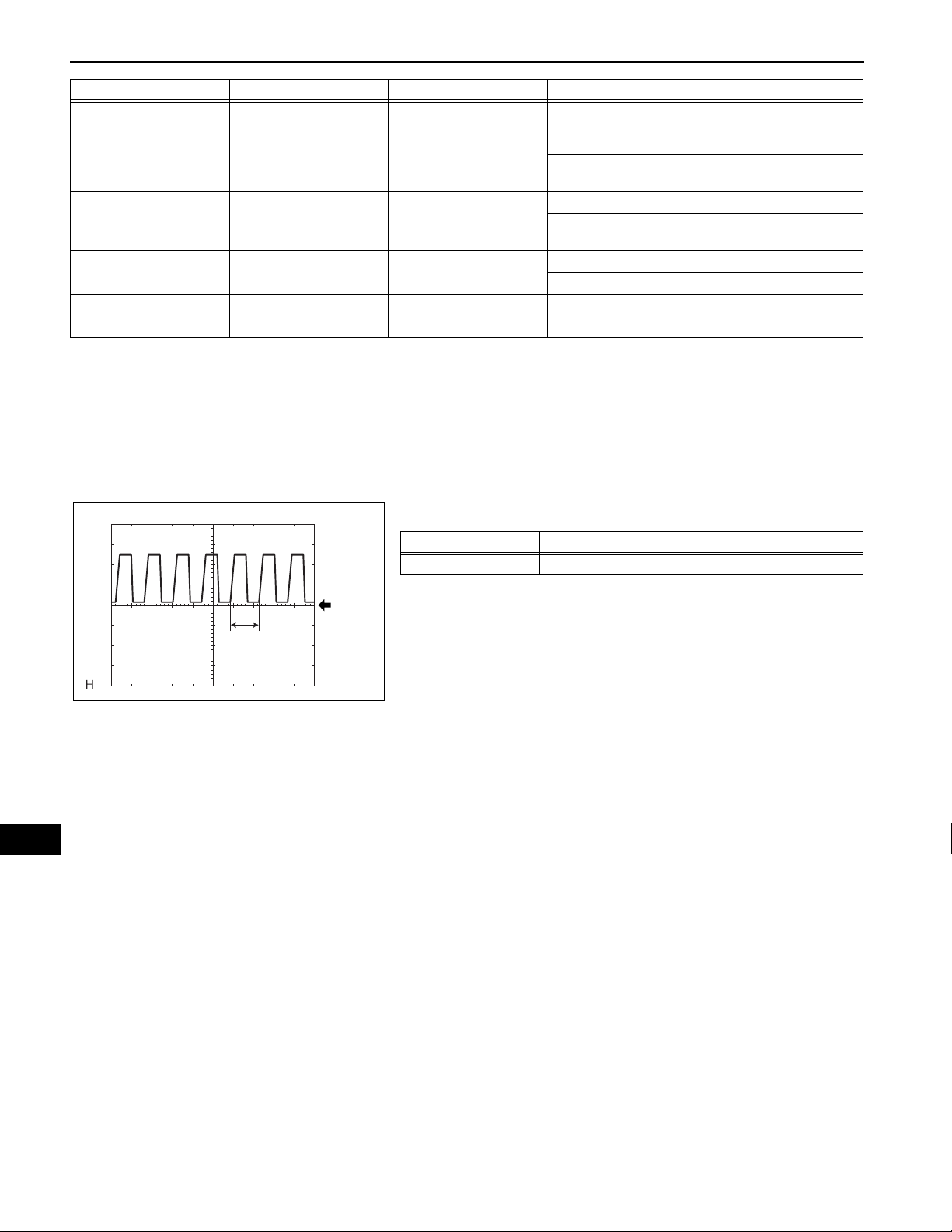
(1) Waveform 1
Item Contents
Tool setting 5 V/DIV., 5 ms./DIV.
A
GND
HINT:
If the ambient light becomes brighter, width A
becomes narrower.
B113714E01
CG
SG
CANH
SIL
LIGHTING – LIGHTING SYSTEM
DIAGNOSIS SYSTEM
1. DESCRIPTION
(a) Lighting system data and the Diagnostic Trouble
Codes (DTCs) can be read from the Data Link
Connector 3 (DLC3) of the vehicle. When the
system seems to be malfunctioning, use the
intelligent tester to check for malfunctions and
perform repairs.
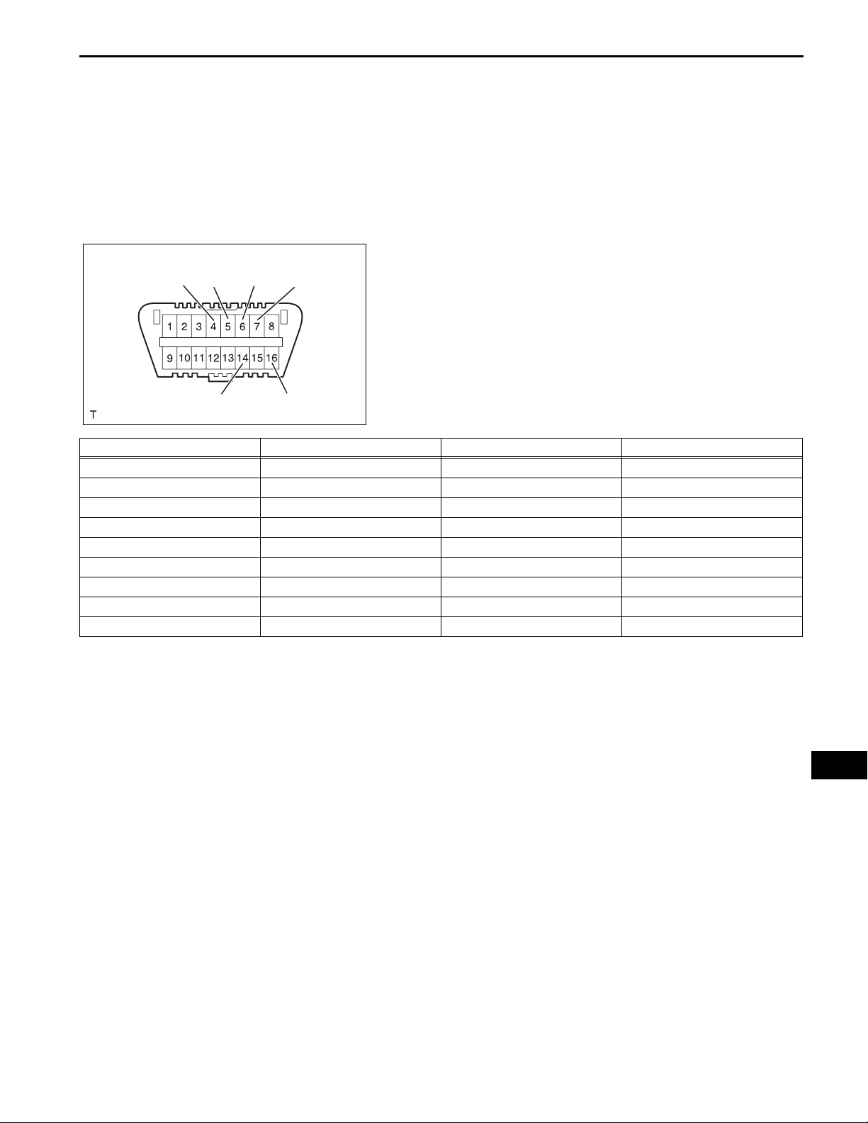
2. CHECK DLC3
(a) The ECU uses ISO 15765-4 for communication.
The terminal arrangement of the DLC3 complies
with SAE J1962 and matches the ISO 15765-4
format.
LI–21
CANL
Symbols (Terminal No.) Terminal Description Condition Specified Condition
SIL (7) - SG (5) Bus "+" line During transmission Pulse generation
CG (4) - Body ground Chassis ground Always Below 1 Ω
SG (5) - Body ground Signal ground Always Below 1 Ω
BAT (16) - Body ground Battery positive Always 11 to 14 V
CANH (6) - CANL (14) CAN bus line Ignition switch off* 54 to 69 Ω
CANH (6) - CG (4) HIGH-level CAN bus line Ignition switch off* 200 Ω or higher
CANL (14) - CG (4) LOW-level CAN bus line Ignition switch off* 200 Ω or higher
CANH (6) - BAT (16) HIGH-level CAN bus line Ignition switch off* 6 kΩ or higher
CANL (14) - BAT (16) LOW-level CAN bus line Ignition switch off* 6 kΩ or higher
BAT
H100769E16
NOTICE:
*Before measuring the resistance, leave the
vehicle as is for at least 1minute and do not
operate the ignition switch, any other switches,
or the doors.
If the result is not as specified, the DLC3 may have
a malfunction. Repair or replace the harness and
connector.
LI
LI–22
LIGHTING – LIGHTING SYSTEM
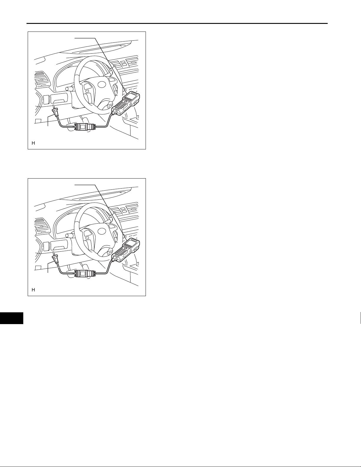
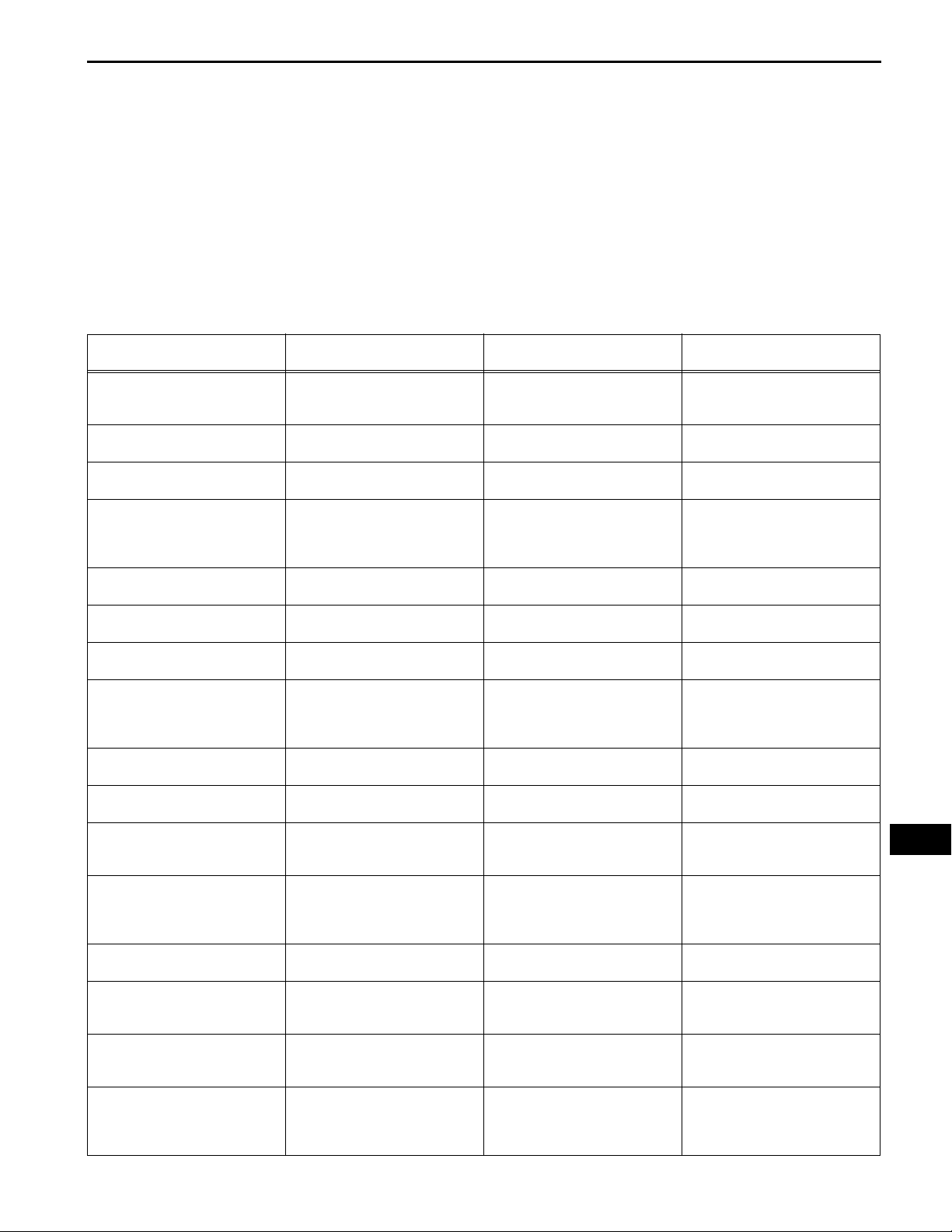
Intelligent Tester
DLC3
Intelligent Tester
DLC3
CAN VIM
CAN VIM
C131977E10
C131977E10
(b) Connect the cable of the intelligent tester to the
DLC3, turn the ignition switch on (IG) and attempt to
use the tester. If the display indicates that a
communication error has occurred, there is a
problem either with the vehicle or with the tester.
HINT:
• If communication is normal when the tester is
connected to another vehicle, inspect the DLC3
of the original vehicle.
• If communication is still not possible when the
tester is connected to another vehicle, the
problem may be in the tester itself. Consult the
Service Department listed in the tester's
instruction manual.
3. INSPECT BATTERY VOLTAGE
Standard voltage:
11 to 14 V
If the voltage is below 11 V, recharge or replace the
battery before proceeding.
DTC CHECK / CLEAR
1. CHECK DTC
(a) Connect the intelligent tester to the DLC3.
(b) Turn the ignition switch on (IG).
(c) Read the DTCs by following the directions on the
tester screen.
HINT:
Please refer to the intelligent tester operator's
manual for further details.
2. CLEAR DTC
(a) Connect the intelligent tester to the DLC3.
(b) Turn the ignition switch on (IG).
(c) Erase the DTCs by following the directions on the
tester screen.
HINT:
Please refer to the intelligent tester operator's
manual for further details.
LI
MAIN BODY (MAIN BODY ECU):
Item
ACC SW
IG SW
D DOR CTY SW
P DOR CTY SW
RR DOR CTY SW
RL DOR CTY SW
D LOCK POS SW
P LOCK POS SW
RR LOCK POS SW
(with Smart Key System)
RL. LOCK POS SW
(with Smart Key System)
DIMMER SW
HIGH FLASHER SW
F FOG LIGHT SW
AUTO LIGHT SW
HEAD LIGHT SW
TAIL LIGHT SW
Measurement Item / Display
Ignition switch or engine switch
ACC signal / ON or OFF
Ignition switch or engine switch
IG signal / ON or OFF
Driver side door courtesy switch
signal / ON or OFF
Passenger side door courtesy
switch signal / ON or OFF
Rear right door courtesy switch
signal / ON or OFF
Rear left door courtesy switch
signal / ON or OFF
Driver side door lock position
switch signal / ON or OFF
Passenger side door lock position
switch signal / ON or OFF
Rear right door lock position
switch signal / ON or OFF
Rear left door lock position switch
signal / ON or OFF
Dimmer switch HIGH signal / ON
or OFF
Dimmer switch HIGH FLASH
signal / ON or OFF
Fog light switch signal / ON or
OFF
Light control switch AUTO signal /
ON or OFF
Light control switch HEAD signal /
ON or OFF
Light control switch TAIL signal /
ON or OFF
LIGHTING – LIGHTING SYSTEM
DATA LIST / ACTIVE TEST
1. READ DATA LIST
HINT:
Using the intelligent tester DATA LIST allows switch,
actuator and other item values to be read without
removing any parts. Reading the DATA LIST early in
troubleshooting is one way to save time.
(a) Connect the intelligent tester to the DLC3.
(b) Turn the ignition switch on (IG).
(c) Read the DATA LIST according to the display on the
tester.
(Range)
Normal Condition Diagnostic Note
ON: Ignition switch on (ACC or
IG)
OFF: Ignition switch off
ON: Ignition switch on (IG)
OFF: Ignition switch off
ON: Driver side door is open
OFF: Driver side door is closed
ON: Front passenger side door is
open
OFF: Front passenger side door
is closed
ON: Rear right door is open
OFF: Rear right door is closed
ON: Rear left door is open
OFF: Rear left door is closed
ON: Driver side door is unlocked
OFF: Driver side door is locked
ON: Front passenger side door is
unlocked
OFF: Front passenger side door
is locked
ON: Rear right door is unlocked
OFF: Rear right door is locked
ON: Rear left door is unlocked
OFF: Rear left door is locked
ON: Dimmer switch in HIGH or
HIGH FLASH
OFF: Dimmer switch in LOW
ON: Dimmer switch in HIGH
FLASH
OFF: Dimmer switch not in HIGH
FLASH
ON: Fog light switch ON
OFF: Fog light switch OFF
ON: Light control switch in AUTO
OFF: Light control switch not in
AUTO
ON: Light control switch in HEAD
OFF: Light control switch not in
HEAD
ON: Light control switch in TAIL or
HEAD
OFF: Light control switch not in
TAIL or HEAD
LI–23
-
-
-
-
-
-
-
-
-
-
-
-
-
-
-
-
LI
LI–24
LIGHTING – LIGHTING SYSTEM
Item
ILLUMINATE RATE
PARKING BRAKE SW
Measurement Item / Display
Illumination rate information / 0
ms. to 99.99 ms.
Parking brake switch signal / ON
or OFF
MAIN BODY (MAIN BODY ECU):
Item Test Details Diagnostic Note
F FOG LIGHT RLY Front fog light relay ON / OFF -
HEAD LIGHT Headlight relay ON / OFF -
HEAD LIGHT (HI) High beam headlights ON / OFF -
TAIL LIGHT Taillight ON / OFF -
DIMMER SIG Dimmer signal ON / OFF -
ILLUMI OUTPUT
(Range)
Normal Condition Diagnostic Note
0.8 ms. to 22.0 ms. (Value is
output according to ambient
illuminance)
ON: Parking brake switch is ON
OFF: Parking brake switch is OFF
2. PERFORM ACTIVE TEST
HINT:
Performing the intelligent tester ACTIVE TEST allows a
relay, VSV, actuator, and other items to be operated
without removing any parts. Performing the ACTIVE
TEST early in troubleshooting is one way to save time.
The DATA LIST can be displayed during the ACTIVE
TEST.
(a) Connect the intelligent tester to the DLC3.
(b) Turn the ignition switch on (IG).
(c) Perform the ACTIVE TEST according to the display
on the tester.
Interior light and ignition key cylinder light ON
/ OFF (Interior light switch in DOOR position
and all doors are closed)
-
-
-
LI
LIGHTING SYSTEM:
DTC No. Detection Item Suspected Area See page
B1244 Light Sensor Circuit Malfunction 1. Automatic light control sensor
LIGHTING – LIGHTING SYSTEM
DIAGNOSTIC TROUBLE CODE CHART
2. Harness or connector
3. Main body ECU (Instrument
panel J/B)
LI–25
LI-23
LI
LI–26
LIGHTING – LIGHTING SYSTEM
DTC B1244 Light Sensor Circuit Malfunction
DESCRIPTION
The automatic light control sensor detects ambient light, converts it into an elect rical signal, and output s it
to the main body ECU. The main body ECU turns on or off the headlights and taillights according to the
signal.
DTC No. DTC Detecting Condition Trouble Area
• Automatic light control sensor
• Harness or connector
• Main body ECU (Instrument panel J/B)
B1244
WIRING DIAGRAM
• Malfunction in automatic light control sensor
• Open or short in automatic light control sensor
circuit
E11
Automatic Light Control Sensor
CLTB
CLTS
CLTE
*1: Manual A/C *2: Automatic A/C
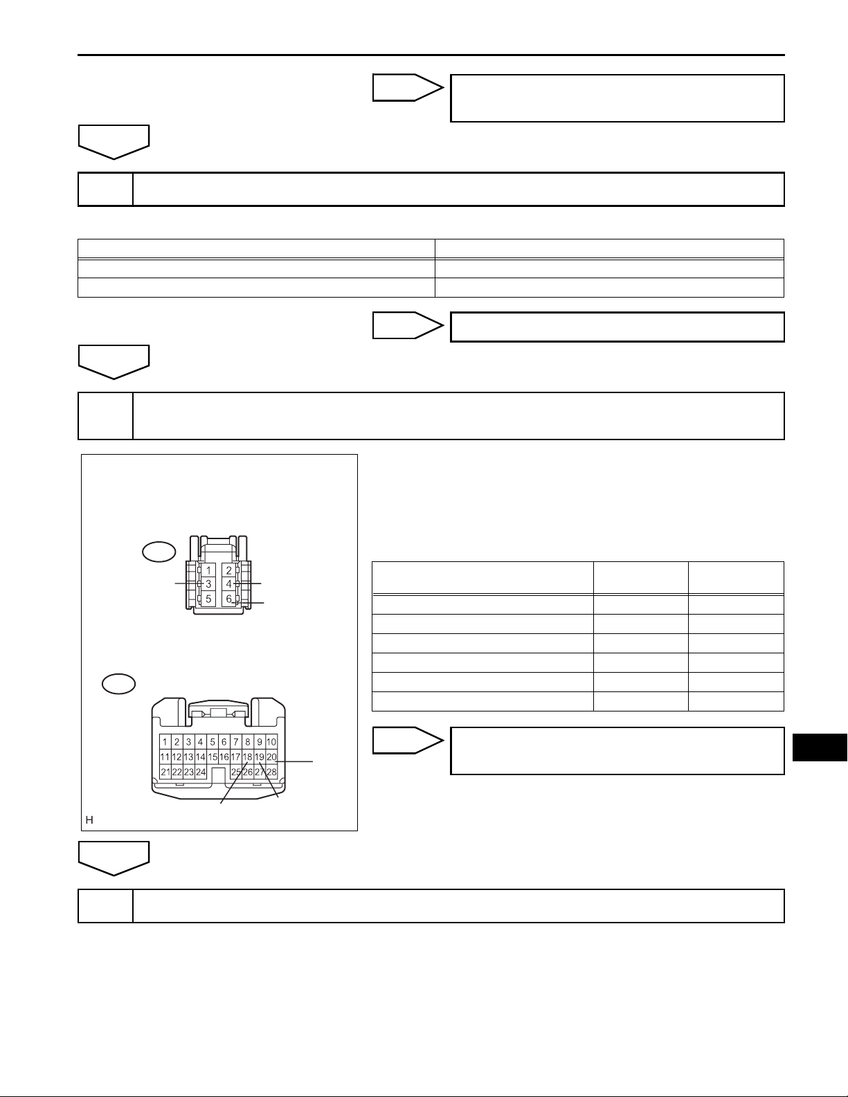
INSPECTION PROCEDURE
LI
3 (*1)
6 (*2)
4 (*1)
5 (*2)
6 (*1)
3 (*2)
E6
Main Body ECU
CLTB
20
CLTS
19
CLTE
18
E124321E04
READ VALUE OF INTELLIGENT TESTER
1
MAIN BODY (MAIN BODY ECU):
Item
ILLUMINATE RATE
Measurement Item / Display
Illumination rate information / 0
ms to 99.99 ms
(Range)
(a) Connect the intelligent tester to the DLC3.
(b) Turn the ignition switch on (IG) and turn the intelligent
tester main switch on.
(c) Select the item below in the DATA LIST, and read the
display on the intelligent tester.
Normal Condition Diagnostic Note
0.8 ms to 22.0 ms (Value is output
according to ambient illuminance)
-
OK:
Normal condition listed above is displayed.
LIGHTING – LIGHTING SYSTEM
LI–27
OK
REPLACE INSTRUMENT PANEL JUNCTION
BLOCK ASSEMBLY
NG
CHECK VEHICLE CONDITION
2
Result
Vehicle Condition Proceed to
Manual Air Conditioning System A
Automatic Air Conditioning System B
B
Go to step 6
A
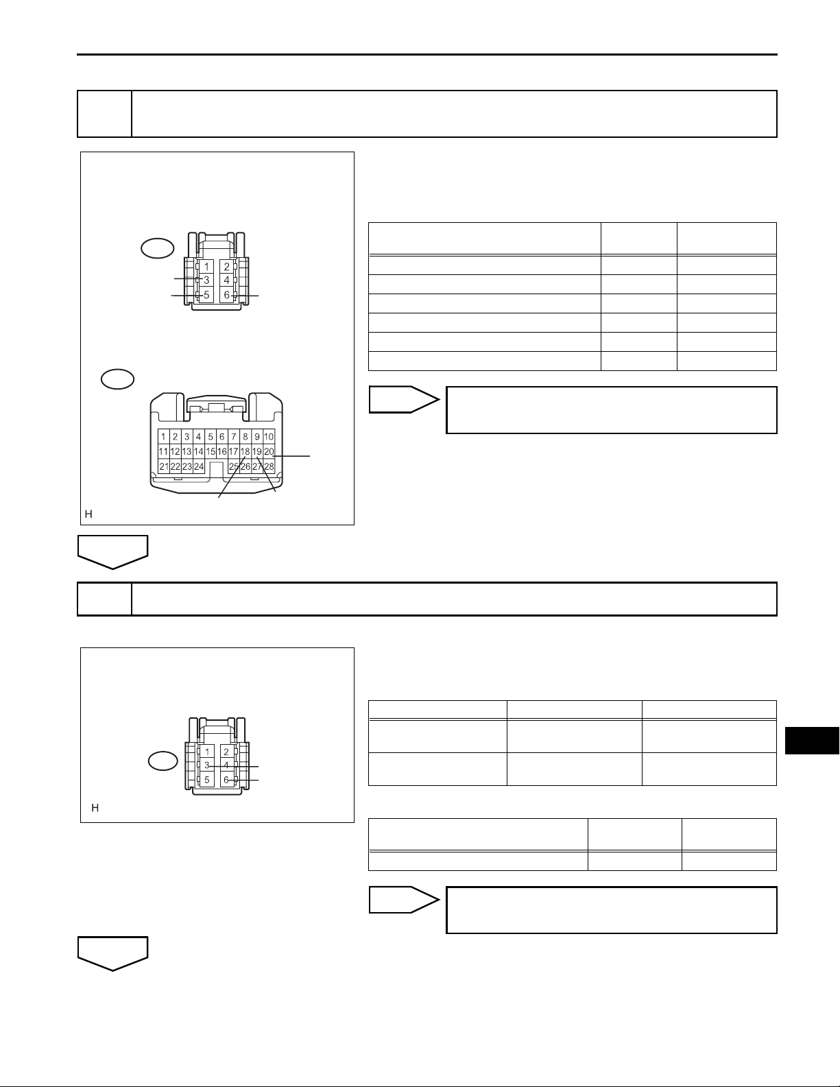
CHECK HARNESS AND CONNECTOR (MAIN BODY ECU - AUTOMATIC LIGHT CONTROL
3
SENSOR)
(a) Disconnect the E11 automatic light control sensor
Wire Harness Side:
connector.
(b) Disconnect the E6 main body ECU connector.
Automatic Light Control Sensor
(c) Measure the resistance according to the value(s) in the
table below.
Standard resistance
Tester Connection Condition
E6-18 (CLTE) - E11-6 (CLTE) Always Below 1 Ω
E6-19 (CLTS) - E11-4 (CLTS) Always Below 1 Ω
E6-20 (CLTB) - E11-3 (CLTB) Always Below 1 Ω
E6-18 (CLTE) - Body ground Always 10 kΩ or higher
E6-19 (CLTS) - Body ground Always 10 kΩ or higher
E6-20 (CLTB) - Body ground Always 10 kΩ or higher
E6
E11
CLTB
CLTS
CLTE
Main Body ECU
Specified
Condition
CLTE
NG
CLTB
CLTS
E121476E03
REPAIR OR REPLACE HARNESS OR
CONNECTOR
OK
INSPECT MAIN BODY ECU (INSTRUMENT PANEL JUNCTION BLOCK ASSEMBLY)
4
(a) Reconnect the main body ECU connector.
LI
LI–28
LIGHTING – LIGHTING SYSTEM
Wire Harness Side:
Automatic Light Control Sensor
E11
CLTB
OK
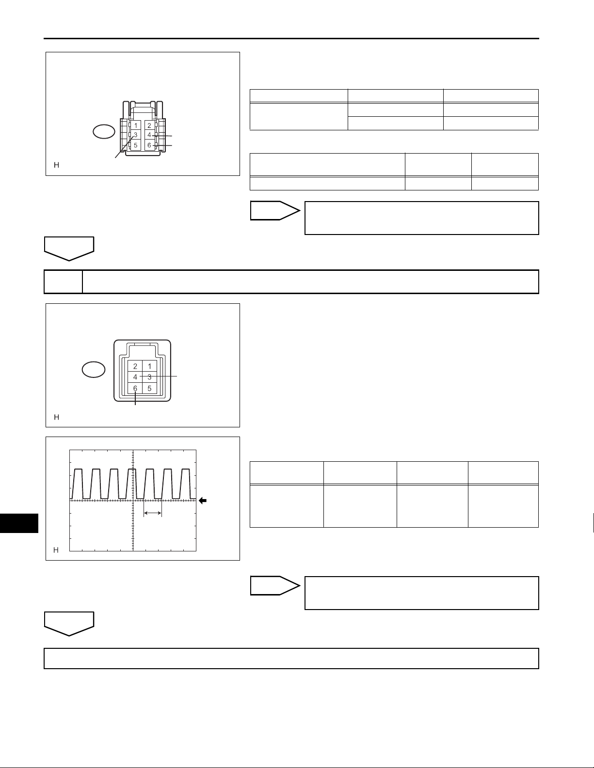
INSPECT AUTOMATIC LIGHT CONTROL SENSOR
5
Automatic Light Control Sensor
CLTS
CLTE
B109993E15
(b) Measure the voltage and resistance according to the
value(s) in the table below.
Standard voltage
Tester Connection Condition Specified Condition
E11-3 (CLTB) - E11-6
(CLTE)
Ignition switch off Below 1 V
Ignition switch on (IG) 10 to 14 V
Standard resistance
Tester Connection Condition
E11-6 (CLTE) - Body ground Always Below 1 Ω
NG
REPLACE INSTRUMENT PANEL JUNCTION
Specified
Condition
BLOCK ASSEMBLY
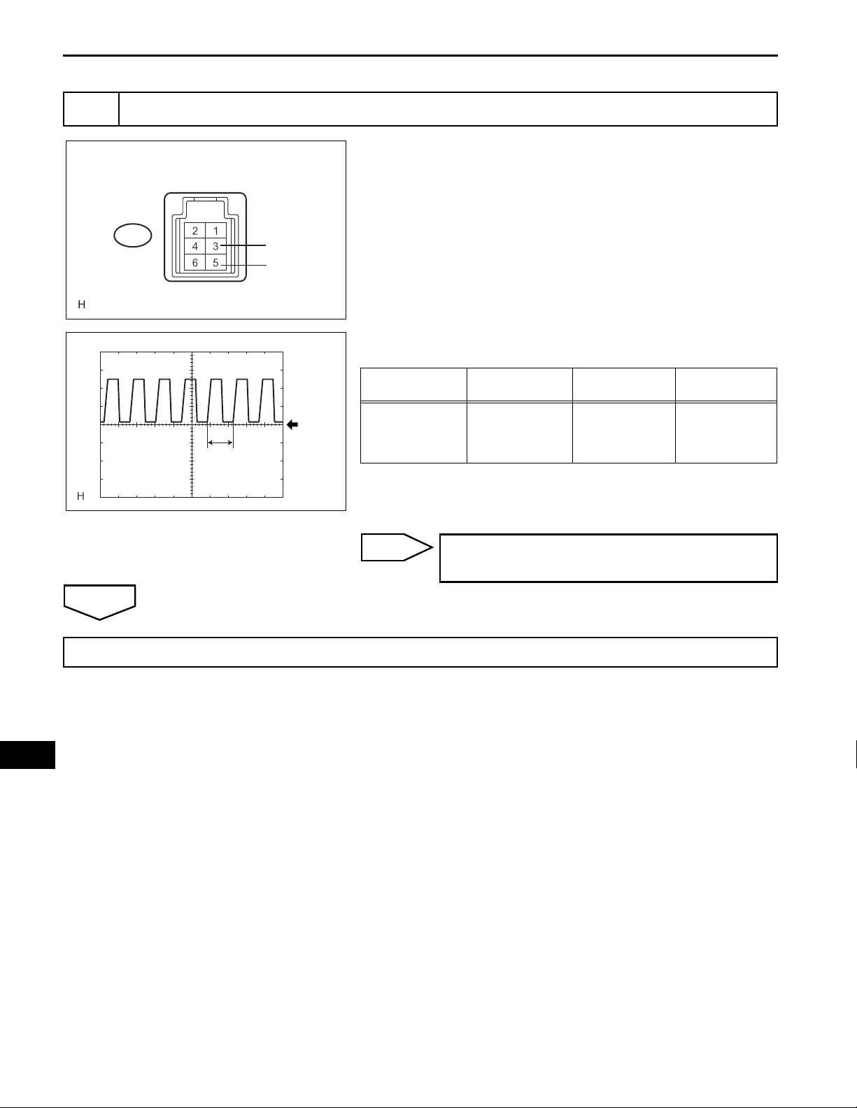
(a) Reconnect the automatic light control sensor connector.
(b) Connect an oscilloscope to the automatic light control
sensor connector.
LI
OK
E11
CLTE
CLTS
E121468E03
(c) Check the waveform.
OK
Tester
Connection
A
GND
E11-6 (CLTE) -
E11-4 (CLTS)
Tool Setting Condition
Ignition switch
5 V/DIV., 5 ms./
DIV.
on (IG), light
control switch in
AUTO
Specified
Condition
Correct
waveform is as
shown
HINT:
B113714E01
If the ambient light becomes brighter, width A becomes
narrower.
NG
REPLACE AUTOMATIC LIGHT CONTROL
SENSOR
REPLACE INSTRUMENT PANEL JUNCTION BLOCK ASSEMBLY
LIGHTING – LIGHTING SYSTEM
CHECK HARNESS AND CONNECTOR (MAIN BODY ECU - AUTOMATIC LIGHT CONTROL
6
SENSOR)
(a) Disconnect the E11 automatic light control sensor
Wire Harness Side:
connector.
(b) Disconnect the E6 main body ECU connector.
Automatic Light Control Sensor
E11
CLTE
CLTS
Main Body ECU
E6
CLTB
Standard resistance
Tester Connection Condition
E6-18 (CLTE) - E11-3 (CLTE) Always Below 1 Ω
E6-19 (CLTS) - E11-5 (CLTS) Always Below 1 Ω
E6-20 (CLTB) - E11-6 (CLTB) Always Below 1 Ω
E6-18 (CLTE) - Body ground Always 10 kΩ or higher
E6-19 (CLTS) - Body ground Always 10 kΩ or higher
E6-20 (CLTB) - Body ground Always 10 kΩ or higher
NG
REPAIR OR REPLACE HARNESS OR
CONNECTOR
LI–29
Specified
Condition
CLTE
OK
INSPECT MAIN BODY ECU (INSTRUMENT PANEL JUNCTION BLOCK ASSEMBLY )
7
Wire Harness Side:
Automatic Light Control Sensor
E11
CLTS
CLTE
CLTB
CLTB
E121476E04
B109993E16
(a) Reconnect the main body ECU connector.
(b) Measure the voltage and resistance according to the
value(s) in the table below.
Standard voltage
Tester Connection Condition Specified Condition
E11-6 (CLTB) - E11-3
(CLTE)
E11-6 (CLTB) - E11-3
(CLTE)
Ignition switch off Below 1 V
Ignition switch on (IG) 10 to 14 V
Standard resistance
Tester Connection Condition
E11-3 (CLTE) - Body ground Always Below 1 Ω
Specified
Condition
LI
OK
NG
REPLACE INSTRUMENT PANEL JUNCTION
BLOCK ASSEMBLY
LI–30
8
LIGHTING – LIGHTING SYSTEM
INSPECT AUTOMATIC LIGHT CONTROL SENSOR
(a) Reconnect the automatic light control sensor connector.
Automatic Light Control Sensor
(b) Connect an oscilloscope to the automatic light control
sensor connector.
OK
E11
CLTE
CLTS
E121468E04
(c) Check the waveform.
OK
Tester
Connection
A
GND
E11-3 (CLTE) -
E11-5 (CLTS)
Tool Setting Condition
Ignition switch
5 V/DIV., 5 ms./
DIV.
on (IG), light
control switch in
AUTO
Specified
Condition
Correct
waveform is as
shown
HINT:
B113714E01
If the ambient light becomes brighter, width A becomes
narrower.
NG
REPLACE AUTOMATIC LIGHT CONTROL
SENSOR
REPLACE INSTRUMENT PANEL JUNCTION BLOCK ASSEMBLY
LI

LIGHTING – LIGHTING SYSTEM
LI–31
Ignition Switch Circuit
DESCRIPTION
This circuit detects the state of the ignition switch or engine switch, and sends it to the main body ECU.
WIRING DIAGRAM
without Smart Key System:
E23
Ignition Switch
ACC
2
IG1
1
ALT
AM1
Main Body ECU
Instrument Panel J/B
1
IA
3
II
4
4
II
9
II
10
IF
AM1
ACC
5
2
5
2
322
1
IG1
3
1
ECU-ACC
ECU IG No. 1
15
ACC
IG
FL MAIN
Battery
LI
E121497E02

LI–32
LIGHTING – LIGHTING SYSTEM
with Smart Key System:
ALT
Instrument Panel J/B
1
IA
3
II
10
IF
9
II
Main Body ECU
ACC
5
2
IG1
5
2
AM2
322
1
3
1
ECU-ACC
ECU-IG No. 1
6
E7
15
ACC
IG
AM1
FL MAIN
Battery
LI
INSPECTION PROCEDURE
E52 Engine SW
5
GND SS1
4
EOM
SS2
22
E7
ACCD
3
IG1D
E7
7
2
17
E7
16
E7
SSW1
SSW2
E121498E01
READ VALUE OF INTELLIGENT TESTER
1
(a) Connect the intelligent tester to the DLC3.
(b) Turn the ignition switch on (IG) and turn the intelligent
tester main switch on.

MAIN BODY (MAIN BODY ECU):
Item
ACC SW
IG SW
Measurement Item / Display
Ignition switch or engine switch
ACC signal / ON or OFF
Ignition switch or engine switch
IG signal / ON or OFF
LIGHTING – LIGHTING SYSTEM
(c) Select the items below in the DATA LIST, and read the
display on the intelligent tester.
(Range)
Normal Condition Diagnostic Note
ON: Ignition switch on (IG or
ACC)
OFF: Ignition switch off
ON: Ignition switch on (IG)
OFF: Ignition switch off
OK:
Normal conditions listed above are displayed.
LI–33
-
-
NG
INSPECT ACC RELAY
2
3
5
2
OK
OK
PROCEED TO NEXT CIRCUIT INSPECTION
SHOWN IN PROBLEM SYMPTOMS TABLE
(a) Remove the ACC relay from the instrument panel J/B
3
assembly.
(b) Measure the resistance according to the value(s) in the
table below.
Standard resistance
Tester Connection Specified Condition
10 kΩ or higher
3 - 5
511
2
B087894E05
NG
REPLACE ACC RELAY
Below 1 Ω (When battery voltage is applied to
terminals 1 and 2)
INSPECT NO. 1 IGNITION RELAY
3
3
3
5
2
511
2
OK
B087894E05
(a) Remove the No. 1 ignition relay from the instrument
panel J/B assembly.
(b) Measure the resistance according to the value(s) in the
table below.
Standard resistance
Tester Connection Specified Condition
10 kΩ or higher
NG
3 - 5
REPLACE NO. 1 IGNITION RELAY
Below 1 Ω (When battery voltage is applied to
terminals 1 and 2)
LI

LI–34
4
LIGHTING – LIGHTING SYSTEM
CHECK HARNESS AND CONNECTOR (INSTRUMENT PANEL J/B ASSEMBLY - BATTERY
AND GROUND)
Wire Harness Side:
Instrument Panel J/B Assembly
Wire Harness Side:
Instrument Panel J/B Assembly
IA
E121505E01
IF
E121504E01
(a) Disconnect the IA instrument panel J/B assembly
connector.
(b) Measure the voltage according to the value(s) in the
table below.
Standard voltage
Tester Connection Condition Specified Condition
IA-1 - Body ground Always 10 to 14 V
(c) Disconnect the IF instrument panel J/B assembly
connector.
(d) Measure the resistance according to the value(s) in the
table below.
Standard resistance
Tester Connection Condition Specified Condition
IF-10 - Body ground Always Below 1 Ω
NG
REPAIR OR REPLACE HARNESS OR
CONNECTOR
OK
CHECK VEHICLE CONDITION
5
(a) Check the vehicle condition.
Result
Condition Proceed to
without Smart Key System A
with Smart Key System B
LI
B
Go to step 8
A

LIGHTING – LIGHTING SYSTEM
CHECK HARNESS AND CONNECTOR (INSTRUMENT PANEL J/B ASSEMBLY - IGNITION
6
SWITCH)
LI–35
Wire Harness Side:
Instrument Panel J/B Assembly
Ignition Switch
IG1
ACC
OK
II
E23
AM1
E121503E01
(a) Disconnect the E23 ignition switch connector.
(b) Disconnect the II instrument panel J/B assembly
connector.
(c) Measure the resistance according to the value(s) in the
table below.
Standard resistance
Tester Connection Condition Specified Condition
II-3 - E23-2 (ACC) Always Below 1 Ω
II-4 - E23-4 (AM1) Always Below 1 Ω
II-9 - E23-1 (IG1) Always Below 1 Ω
II-3 - Body ground Always 10 kΩ or higher
II-4 - Body ground Always 10 kΩ or higher
II-9 - Body ground Always 10 kΩ or higher
NG
REPAIR OR REPLACE HARNESS OR
CONNECTOR
INSPECT IGNITION SWITCH
7
(a) Inspect the ignition switch (See page ST-155)
OK:
Ignition switch is normal.
NG
OK
REPLACE INSTRUMENT PANEL J/B ASSEMBLY
REPLACE IGNITION SWITCH
LI

LI–36
8
LIGHTING – LIGHTING SYSTEM
CHECK HARNESS AND CONNECTOR (BATTERY - MAIN BODY ECU)
Wire Harness Side:
Main Body ECU
E7
OK
CHECK HARNESS AND CONNECTOR (INSTRUMENT PANEL J/B ASSEMBLY - MAIN
9
BODY ECU)
Wire Harness Side:
Instrument Panel J/B Assembly
Main Body ECU
AM1
II
E121506E01
(a) Disconnect the E7 main body ECU connector.
(b) Measure the voltage according to the value(s) in the
table below.
Standard voltage
Tester Connection Condition Specified Condition
E7-6 (AM1) - Body
ground
NG
REPAIR OR REPLACE HARNESS OR
Always 10 to 14 V
CONNECTOR
(a) Disconnect the E7 main body ECU connector.
(b) Disconnect the II instrument panel J/B assembly
connector.
(c) Measure the resistance according to the value(s) in the
table below.
Standard resistance
Tester Connection Condition Specified Condition
II-3 - E7-22 (ACCD) Always Below 1 Ω
II-9 - E7-3 (IG1D) Always Below 1 Ω
II-3 - Body ground Always 10 kΩ or higher
II-9 - Body ground Always 10 kΩ or higher
LI
OK
E7
E121484E02
NG
REPAIR OR REPLACE HARNESS OR
CONNECTOR

LIGHTING – LIGHTING SYSTEM
LI–37
10
CHECK HARNESS AND CONNECTOR (ENGINE SWITCH - MAIN BODY ECU AND BODY
GROUND)
Wire Harness Side:
Engine Switch
SS2
Main Body ECU
SS1
E52
E7
SSW1
(a) Disconnect the E52 engine switch connector.
(b) Disconnect the E7 main body ECU connector.
(c) Measure the resistance according to the value(s) in the
table below.
Standard resistance
Tester Connection Condition Specified Condition
E52-7 (SS1) - E7-17 (SSW1) Always Below 1 Ω
E52-2 (SS2) - E7-16 (SSW2) Always Below 1 Ω
E52-5 (GND) - Body ground Always 10 kΩ or higher
E52-4 (EOM) - Body ground Always 10 kΩ or higher
NG
REPAIR OR REPLACE HARNESS OR
CONNECTOR
SSW2
E121502E01
OK
11
INSPECT ENGINE SWITCH
(a) Inspect the engine switch (See page ST-153).
OK:
Engine switch is normal.
NG
OK
REPLACE INSTRUMENT PANEL J/B ASSEMBLY
REPLACE ENGINE SWITCH
LI

LI–38
LIGHTING – LIGHTING SYSTEM
Headlight Relay Circuit
DESCRIPTION
The main body ECU receives a light control switch HEAD signal from the headlight dimmer switch
assembly, and turns the low beam headlights on. The headlight relay is installed in the power distributor
(engine room J/B assembly).
WIRING DIAGRAM
Main Body ECU
Engine Room J/B
1
1G
FL MAIN
H-LP (LL)
H-LP (RL)
H-LP (LL)
H-LP (RL)
A49
Headlight (RH Low)
12
A45
Headlight (LH Low)
9
1D
4
1B
5
1B
Instrument Panel J/B
3
ID
HRLY
8
LI
Battery
INSPECTION PROCEDURE
PERFORM ACTIVE TEST BY INTELLIGENT TESTER
1
12
E121488E01
(a) Connect the intelligent tester to the DLC3.

MAIN BODY (MAIN BODY ECU):
Item Test Details Diagnostic Note
HEAD RELAY Headlight Relay ON / OFF -
LIGHTING – LIGHTING SYSTEM
(b) Turn the ignition switch on (IG) and turn the intelligent
tester main switch on.
(c) Select the item below in the ACTIVE TEST and then
check that the relay operates.
OK:
Headlight relay operates. (Low beam headlights
illuminate.)
LI–39
OK
PROCEED TO NEXT CIRCUIT INSPECTION
SHOWN IN PROBLEM SYMPTOMS TABLE
NG
INSPECT INSTRUMENT PANEL JUNCTION BLOCK ASSEMBLY
2
(a) Measure the voltage according to the value(s) in the
Instrument Panel J/B Assembly
table below.
Standard voltage
ID
HRLY
E121528E01
Tester Connection Condition Specified Condition
ID-3 (HRLY) - Body
ground
OK
Go to step 6
Light control switch
OFF → HEAD
NG
CHECK HARNESS AND CONNECTOR (BATTERY - ENGINE ROOM J/B ASSEMBLY)
3
10 to 14 V → Below 1 V
Wire Harness Side:
Engine Room
J/B Assembly
OK
INSPECT ENGINE ROOM J/B BLOCK ASSEMBLY
4
(a) Disconnect the 1G engine room J/B assembly connector .
(b) Measure the voltage according to the value(s) in the
table below.
Standard voltage
1
1G
B074501E17
Tester Connector Condition Specified Condition
1G - Body ground Always 10 to 14 V
NG
REPAIR OR REPLACE HARNESS OR
CONNECTOR
LI
(a) Reconnect the 1G engine room J/B assembly connector.

LI–40
Engine Room J/B Assembly
1D
LIGHTING – LIGHTING SYSTEM
(b) Disconnect the 1D engine room J/B assembly connector.
(c) Measure the voltage according to the value(s) in the
table below.
Standard voltage
Tester Connection Condition Specified Condition
1D-9 - Body ground Always 10 to 14 V
OK
CHECK HARNESS AND CONNECTOR (ENGINE ROOM J/B ASSEMBLY - INSTRUMENT
5
PANEL J/B ASSEMBLY)
Wire Harness Side:
Instrument Panel J/B Assembly
HRLY
OK
E121531E01
ID
E121479E03
NG
REPLACE ENGINE ROOM JUNCTION
BLOCK ASSEMBLY (POWER DISTRIBUTOR)
(a) Reconnect the 1D engine room J/B assembly connector.
(b) Disconnect the ID instrument panel J/B assembly
connector.
(c) Measure the voltage according to the value(s) in the
table below.
Standard voltage
Tester Connection Condition Specified Condition
ID-3 (HRLY) - Body
ground
NG
REPAIR OR REPLACE HARNESS OR
Always 10 to 14 V
CONNECTOR
REPLACE INSTRUMENT PANEL JUNCTION BLOCK ASSEMBLY
LI

LIGHTING – LIGHTING SYSTEM
INSPECT ENGINE ROOM JUNCTION BLOCK ASSEMBLY
6
LI–41
Power Distributer (Engine Room J/B)
H-LP (RL)
Terminal
H-LP (LL)
Terminal
OK
E121533E01
(a) Remove the H-LP (RL) fuse and H-LP (LL) fuse from the
engine room J/B assembly.
(b) Measure the voltage between the loading slot of each
fuse and body ground.
Standard voltage
Tester Connection Condition Specified Condition
H-LP (RL) Terminal -
Body ground
H-LP (LL) Terminal -
Body ground
NG
REPLACE ENGINE ROOM JUNCTION
Light control switch in
HEAD
Light control switch in
HEAD
10 to 14 V
10 to 14 V
BLOCK ASSEMBLY (POWER DISTRIBUTOR)
REPAIR OR REPLACE HARNESS OR CONNECTOR (FUSE - BODY GROUND)
LI

LI–42
LIGHTING – LIGHTING SYSTEM
Headlight (HI-BEAM) Circuit
DESCRIPTION
The main body ECU receives dimmer switch HIGH signal and light control switch HEAD signal from the
headlight dimmer switch assembly, and turns the high beam headlights on.
HINT:
When a short circuit occurs between the power distributor (engine room J/B assembly) and high beam
headlight, the power distributor stops the DRL relay operation (Fail-safe function).
WIRING DIAGRAM
Light Control Circuit
DRL
H-LP (LH)
H-LP (RH)
8
1D
9
1D
11
1E
2
1B
3
1B
1
1G
Main Body ECU
Instrument Panel J/BPower Distributor (Engine Room J/B)
9
ID
3
ID
11
8
DRL
HRLY
LI
FL MAIN
Battery
A29
Headlight (RH High)
12
A8
Headlight (LH High)
1
2
E121490E01

INSPECTION PROCEDURE
PERFORM ACTIVE TEST BY INTELLIGENT TESTER
1
MAIN BODY (MAIN BODY ECU):
Item Test Details Diagnostic Note
HEAD LIGHT (HI) High beam headlights ON / OFF -
LIGHTING – LIGHTING SYSTEM
(a) Connect the intelligent tester to the DLC3.
(b) Turn the ignition switch on (IG) and turn the intelligent
tester main switch on.
(c) Select the item below in the ACTIVE TEST and then
check that the relay operates.
OK:
Relay operates. (High beam headlights illuminate.)
LI–43
OK
PROCEED TO NEXT CIRCUIT INSPECTION
SHOWN IN PROBLEM SYMPTOMS TABLE
NG
INSPECT INSTRUMENT PANEL JUNCTION BLOCK ASSEMBLY
2
(a) Measure the voltage according to the value(s) in the
Instrument Panel J/B Assembly
table below.
Standard voltage
ID
HRLY DRL
E121528E02
Tester Connection Condition Specified Condition
ID-3 (HRLY) - Body
ground
ID-9 (DRL) - Body
ground
OK
Go to step 6
Light control switch
OFF → HEAD
Light control switch in
HEAD, dimmer switch
LOW → HIGH
10 to 14 V → Below 1 V
10 to 14 V → Below 1 V
NG
CHECK HARNESS AND CONNECTOR (ENGINE ROOM J/B ASSEMBLY - BATTERY AND
3
BODY GROUND)
LI
Wire Harness Side:
Engine Room
J/B Assembly
(a) Disconnect the 1G engine room J/B assembly connector .
(b) Measure the voltage according to the value(s) in the
table below.
Standard voltage
1
1G
B074501E17
Tester Connection Condition Specified Condition
1G-1 - Body ground Always 10 to 14 V

LI–44
LIGHTING – LIGHTING SYSTEM
Wire Harness Side:
Engine Room J/B Assembly
OK
INSPECT ENGINE ROOM JUNCTION BLOCK ASSEMBLY
4
Engine Room J/B Assembly
1D
1E
E121481E01
(c) Disconnect the 1E engine room J/B assembly connector.
(d) Measure the resistance according to the value(s) in the
table below.
Standard resistance
Tester Connection Condition Specified Condition
1E-11 - Body ground Always Below 1 Ω
NG
REPAIR OR REPLACE HARNESS OR
CONNECTOR
(a) Reconnect the 1G and 1E engine room J/B assembly
connectors.
(b) Disconnect the 1D engine room J/B assembly connector.
(c) Measure the voltage according to the value(s) in the
table below.
Standard voltage
Tester Connection Condition Specified Condition
1D-8 - Body ground Always 10 to 14 V
1D-9 - Body ground Always 10 to 14 V
LI
OK
CHECK HARNESS AND CONNECTOR (ENGINE ROOM J/B ASSEMBLY - INSTRUMENT
5
PANEL J/B ASSEMBLY)
Wire Harness Side:
Instrument Panel J/B Assembly
HRLY
DRL
E121531E01
ID
E121479E02
NG
REPLACE ENGINE ROOM JUNCTION
BLOCK ASSEMBLY (POWER DISTRIBUTOR)
(a) Reconnect the 1D engine room J/B assembly connector.
(b) Disconnect the ID instrument panel J/B connector.
(c) Measure the voltage according to the value(s) in the
table below.
Standard voltage
Tester Connection Condition Specified Condition
ID-3 (DRL) - Body
ground
ID-9 (HRLY) - Body
ground
NG
REPAIR OR REPLACE HARNESS OR
Always 10 to 14 V
Always 10 to 14 V
CONNECTOR
OK
REPLACE INSTRUMENT PANEL JUNCTION BLOCK ASSEMBLY

LIGHTING – LIGHTING SYSTEM
CHECK HARNESS AND CONNECTOR (SHORT IN RELAY-DRIVEN CIRCUIT)
6
LI–45
Power Distributor (Engine Room J/B)
H-LP(RH)
H-LP(LH)
NG
E121471E01
(a) Remove the H-LP (RH) fuse from the engine room J/B
assembly.
(b) Turn the light control switch to the HEAD position and
turn the dimmer switch to the HIGH position.
(c) Check if the high beam headlight LH illuminates.
(d) Turn the dimmer switch to the LOW position.
(e) Install the H-LP (RH) fuse and remove the H-LP (LH)
fuse.
(f) Turn the dimmer switch to the HIGH position.
(g) Check if the high beam headlight RH illuminates.
OK:
Either high beam headlight LH or RH illuminates.
OK
REPAIR OR REPLACE HARNESS OR
CONNECTOR (SHORT CIRCUIT BETWEEN
FUSE AND BULB)
INSPECT ENGINE ROOM JUNCTION BLOCK ASSEMBLY
7
H-LP (LH)
Terminal
H-LP (RH)
Terminal
E121532E01
(a) Remove the H-LP (RH) fuse and H-LP (LH) fuse from
the engine room J/B assembly.
(b) Measure the voltage between the loading slot of each
fuse and body ground.
Standard voltage
Tester Connection Condition Specified Condition
H-LP (RH) Terminal -
Body ground
H-LP (LH) Terminal -
Body ground
NG
REPLACE ENGINE ROOM JUNCTION
Light control switch in
HEAD and dimmer
switch in HIGH
Light control switch in
HEAD and dimmer
switch in HIGH
10 to 14 V
10 to 14 V
BLOCK ASSEMBLY (POWER DISTRIBUTOR)
LI

LI–46
OK
REP AIR OR REPLACE HARNESS OR CONNECTOR (OPEN CIRCUIT BETWEEN FUSE AND BODY
GROUND)
LIGHTING – LIGHTING SYSTEM
LI

LIGHTING – LIGHTING SYSTEM
Light Control Switch Circuit
DESCRIPTION
This circuit detects the condition of the headlight dimmer switch assembly.
LI–51
LI

LI–52
WIRING DIAGRAM
E21
Headlight Dimmer Switch Assembly
Fog SW
OFF
ON
LIGHTING – LIGHTING SYSTEM
LFG BFG
Instrument Panel J/B
5
IG
4
Main Body ECU
13
HF
E7
HU
13
28
E6
FFOG
LI
11
17
3
16
Dimmer
SW
Light
Control
SW
HF HL HU ED
Low
High
Flash
DRL-OFF (USA)
OFF (*1)
Auto
Ta il
Head
THAEL
18
20
19
23
E7
17
E6
21
E7 A
TAIL
HEAD
12
*1: Except USA
E121491E02

INSPECTION PROCEDURE
READ VALUE OF INTELLIGENT TESTER
1
MAIN BODY (MAIN BODY ECU):
Item
DIMMER SW
HIGH FLASHER SW
F FOG LIGHT SW
AUTO LIGHT SW
HEAD LIGHT SW
TAIL LIGHT SW
Measurement Item / Display
Dimmer switch HIGH signal / ON
or OFF
Dimmer switch FLASH signal /
ON or OFF
Front fog light switch signal / ON
or OFF
Light control switch AUTO signal /
ON or OFF
Light control switch HEAD signal /
ON or OFF
Light control switch TAIL signal /
ON or OFF
LIGHTING – LIGHTING SYSTEM
(a) Connect the intelligent tester to the DLC3.
(b) Turn the ignition switch on (IG) and turn the intelligent
tester main switch on.
(c) Select the items below in the DATA LIST, and read the
display on the intelligent tester.
(Range)
Normal Condition Diagnostic Note
ON: Dimmer switch in HIGH or
FLASH
OFF: Dimmer switch in neither
HIGH nor FLASH
ON: Dimmer switch in FLASH
OFF: Dimmer switch not in
FLASH
ON: Fog light switch ON
OFF: Fog light switch OFF
ON: Light control switch in AUTO
OFF: Light control switch not in
AUTO
ON: Light control switch in HEAD
OFF: Light control switch not in
HEAD
ON: Light control switch in TAIL or
HEAD
OFF: Light control switch in
neither TAIL nor HEAD
LI–53
-
-
-
-
-
-
OK:
Normal conditions listed above are displayed.
OK
NG
INSPECT HEADLIGHT DIMMER SWITCH ASSEMBLY
2
(a) Inspect the headlight dimmer switch assembly (See
page LI-120).
OK:
Headlight dimmer switch assembly is normal.
NG
OK
PROCEED TO NEXT CIRCUIT INSPECTION
SHOWN IN PROBLEM SYMPTOMS TABLE
LI
REPLACE HEADLIGHT DIMMER SWITCH
ASSEMBLY

LI–54
CHECK HARNESS AND CONNECTOR (INSTRUMENT PANEL J/B ASSEMBLY - SWITCH
3
ASSEMBLY)
Wire Harness Side:
Headlight Dimmer Switch Assembly
BFG
T
LIGHTING – LIGHTING SYSTEM
(a) Disconnect the E21 headlight dimmer switch assembly
connector.
(b) Disconnect the E6 and E7 main body ECU connectors.
(c) Disconnect the IG instrument panel J/B connector.
(d) Measure the resistance according to the value(s) in the
table below.
Standard resistance
LI
LFG
HU
HF
EL
HL HF
A
Main Body ECU
TAIL
A
Main Body ECU
HEAD
E21
H
E7
E6
FFOG
Tester Connection Condition Specified Condition
E21-3 (LFG) - E21-16
(HL)
E21-4 (BFG) - E6-28
(FFOG)
E21-11 (HU) - IG-5 (HU) Always Below 1 Ω
E21-17 (HF) - E7-13 (HF) Always Below 1 Ω
E21-18 (T) - E7-23
(TAIL)
E21-19 (A) - E7-21 (A) Always Below 1 Ω
E21-20 (H) - E6-17
(HEAD)
E21-3 (LFG) - Body
ground
E21-4 (BFG) - Body
ground
E21-11 (HU) - Body
ground
E21-17 (HF) - Body
ground
E21-18 (T) - Body
ground
E21-19 (A) - Body
ground
E21-20 (H) - Body
ground
E21-12 (EL) - Body
ground
Always Below 1 Ω
Always Below 1 Ω
Always Below 1 Ω
Always Below 1 Ω
Always 10 kΩ or higher
Always 10 kΩ or higher
Always 10 kΩ or higher
Always 10 kΩ or higher
Always 10 kΩ or higher
Always 10 kΩ or higher
Always 10 kΩ or higher
Always Below 1 Ω
Instrument Panel J/B Assembly
NG
REPAIR OR REPLACE HARNESS OR
CONNECTOR
HU
IG
E121507E02
OK
REPLACE INSTRUMENT PANEL JUNCTION BLOCK ASSEMBLY

LIGHTING – LIGHTING SYSTEM
LI–47
Front Fog Light Circuit
DESCRIPTION
The main body ECU controls the FOG relay when a signal is received from the headlight dimmer switch
assembly.
WIRING DIAGRAM
Main Body ECU
Instrument Panel Junction Block
TRLY
TAIL
7
3
IL
4
IL
1
IA
ALT
FL MAIN
TAIL
FR FOG
2
3
FOG
1
5
1
5
8
2
3
II
5
ID
1
IC
A1
Fog Light (Front LH)
12
A34
Fog Light (Front RH)
12
4
E7
FFGO
LI
Battery
INSPECTION PROCEDURE
PERFORM ACTIVE TEST BY INTELLIGENT TESTER
1
E121495E02
(a) Connect the intelligent tester to the DLC3.

LI–48
MAIN BODY (MAIN BODY ECU):
Item Test Details Diagnostic Note
F FOG LIGHT RLY Front fog light relay ON / OFF -
LIGHTING – LIGHTING SYSTEM
(b) Turn the ignition switch on (IG) and turn the intelligent
tester main switch on.
(c) Select the item below in the ACTIVE TEST and then
check that the relay operates.
OK:
Front fog light relay operates. (Front fog lights
come on.)
LI
3
2
NG
INSPECT FUSE (FR FOG)
2
OK
INSPECT FOG LIGHT RELAY
3
1
5
1
2
5
3
B060778E87
OK
PROCEED TO NEXT CIRCUIT INSPECTION
SHOWN IN PROBLEM SYMPTOMS TABLE
(a) Remove the FR FOG fuse from the instrument panel J/B
assembly.
(b) Measure the resistance of the fuse.
Standard resistance:
Below 1 Ω
NG
REPLACE FUSE
(a) Remove the front fog light relay from the instrument
panel J/B assembly.
(b) Measure the resistance according to the value(s) in the
table below.
Standard resistance
Tester Connection Specified Condition
10 kΩ or higher
3 - 5
Below 1 Ω (When battery voltage is applied to
terminals 1 and 2)
OK
NG
REPLACE FOG LIGHT RELAY

LIGHTING – LIGHTING SYSTEM
INSPECT INSTRUMENT PANEL JUNCTION BLOCK ASSEMBLY
4
(a) Measure the voltage according to the value(s) in the
Instrument Panel J/B Assembly
table below.
Standard voltage
ID
IC
Tester Connection Condition Specified Condition
IC-1 - Body ground
ID-5 - Body ground
E121539E01
Light control switch in
HEAD, front fog light
switch OFF → ON
Light control switch in
HEAD, front fog light
switch OFF → ON
LI–49
Below 1 V → 10 to 14 V
Below 1 V → 10 to 14 V
OK
REPAIR OR REPLACE HARNESS OR
CONNECTOR (INSTRUMENT PANEL J/B
ASSEMBLY - BODY GROUND)
NG
INSPECT INSTRUMENT PANEL JUNCTION BLOCK ASSEMBLY
5
(a) Measure the voltage according to the value(s) in the
Instrument Panel J/B Assembly
table below.
Standard voltage
IL
E121527E01
Tester Connection Condition Specified Condition
IL-3 - Body ground
NG
REPLACE INSTRUMENT PANEL JUNCTION
Light control switch
OFF → TAIL
Below 1 V → 10 to 14 V
BLOCK ASSEMBLY
OK
CHECK HARNESS AND CONNECTOR (BETWEEN CONNECTOR IL-3 AND CONNECTOR
6
IL-4)
LI
Instrument Panel J/B Assembly
OK
IL
E121527E01
(a) Measure the voltage according to the value(s) in the
table below.
Standard voltage
Tester Connection Condition Specified Condition
IL-4 - Body ground
NG
REPAIR OR REPLACE HARNESS OR
Light control switch
OFF → TAIL
Below 1 V → 10 to 14 V
CONNECTOR

LI–50
7
LIGHTING – LIGHTING SYSTEM
INSPECT INSTRUMENT PANEL JUNCTION BLOCK ASSEMBLY
(a) Disconnect the II instrument panel J/B assembly
Instrument Panel J/B Assembly
connector.
(b) Measure the voltage according to the value(s) in the
II
table below.
Standard voltage
Tester Connection Condition Specified Condition
II-8 - Body ground
Light control switch
OFF → TAIL
Below 1 V → 10 to 14 V
OK
CHECK HARNESS AND CONNECTOR (BODY ECU - INSTRUMENT PANEL JUNCTION
8
BLOCK ASSEMBLY)
Wire Harness Side:
Instrument Panel J/B Assembly
Main Body ECU
II
E121526E01
NG
REPLACE INSTRUMENT PANEL JUNCTION
BLOCK ASSEMBLY
(a) Disconnect the E7 main body ECU connector.
(b) Measure the resistance according to the value(s) in the
table below.
Standard resistance
Tester Connection Condition Specified Condition
E7-4 - II-8 Always Below 1 Ω
NG
REPAIR OR REPLACE HARNESS OR
CONNECTOR
FFGO
LI
E7
E121484E01
OK
REPLACE INSTRUMENT PANEL JUNCTION BLOCK ASSEMBLY

LIGHTING – LIGHTING SYSTEM
Door Courtesy Switch Circuit
DESCRIPTION
The main body ECU detects the condition of the door courtesy switches.
WIRING DIAGRAM
LI–55
*2: with Smart Key System*1: without Smart Key System
Instrument Panel J/B
7
IO
11 11
M6
Door Courtesy
Switch (Driver
Side)
O6
Door Courtesy
Switch (Front
Passenger Side)
O10
Door Courtesy
Switch (Rear RH)
N13
Door Courtesy
Switch (Rear LH)
7 (*2)
5 (*1)
Main Body ECU
24
DCTY
E7
21
E6
PCTY
RCTY
E6
LCTY
17
C
INSPECTION PROCEDURE
READ VALUE OF INTELLIGENT TESTER
1
MAIN BODY (MAIN BODY ECU):
Item
D DOR CTY SW
P DOR CTY SW
RR DOR CTY SW
Measurement Item / Display
Driver side door courtesy switch
signal / ON or OFF
Passenger side door courtesy
switch signal / ON or OFF
Rear right door courtesy switch
signal / ON or OFF
(Range)
B110597E05
(a) Connect the intelligent tester to the DLC3.
(b) Turn the ignition switch on (IG) and turn the intelligent
tester main switch on.
(c) Select the items below in the DATA LIST, and read the
display on the intelligent tester.
Normal Condition Diagnostic Note
ON: Driver side door is open
OFF: Driver side door is closed
ON: Passenger side door is open
OFF: Passenger side door is
closed
ON: Rear right door is open
OFF: Rear right door is closed
-
-
-
LI

LI–56
LIGHTING – LIGHTING SYSTEM
Item
RL DOR CTY SW
Measurement Item / Display
Rear left door courtesy switch
signal / ON or OFF
NG
INSPECT DOOR COURTESY SWITCH
2
OK
(Range)
Normal Condition Diagnostic Note
ON: Rear left door is open
OFF: Rear left door is closed
-
OK:
Normal conditions listed above are displayed.
OK
PROCEED TO NEXT CIRCUIT INSPECTION
SHOWN IN PROBLEM SYMPTOMS TABLE
(a) Inspect the front door courtesy switch (See page LI-129).
(b) Inspect the rear door courtesy switch (See page LI-131).
OK:
Door courtesy switches are normal.
NG
REPLACE DOOR COURTESY SWITCH
LI
CHECK HARNESS AND CONNECTOR (MAIN BODY ECU - DOOR COURTESY SWITCH)
3
Wire Harness Side:
Main Body ECU
(*1)
RCTY
PCTY
Switch
RCTY
O6
O10
E6
E108574E07
(*2)
(a) Check the harness and connector between the main
body ECU and door courtesy switches (passenger side
and rear RH).
(1) Disconnect the E6 main body ECU connector.
(2) Disconnect the O6 and O10 switch connectors.
(3) Measure the resistance according to the value(s) in
the table below.
Standard resistance
Tester Connection Condition Specified Condition
E6-5 (*1) - O10-1 (Rear RH) Always Below 1 Ω
E6-7 (*2) - O10-1 (Rear RH) Always Below 1 Ω
E6-21 (PCTY) - O6-1 (Front
passenger side)
O10-1 (Rear RH) - Body ground Always 10 kΩ or higher
O6-1 (Front passenger side) - Body
ground
Always Below 1 Ω
Always 10 kΩ or higher
HINT:
*1: without Smart Key System
*2: with Smart Key System

Wire Harness Side:
Instrument Panel J/B Assembly
IO
Door Courtesy Switch
N13
LIGHTING – LIGHTING SYSTEM
(b) Check the harness and connector between the
instrument panel J/B assembly and rear LH door
courtesy switch.
(1) Disconnect the IO instrument panel J/B assembly
connector.
(2) Disconnect the N13 switch connector.
(3) Measure the resistance according to the value(s) in
the table below.
Standard resistance
Tester Connection Condition Specified Condition
IO-7 (LCTY) - N13-1 (Rear LH) Always Below 1 Ω
IO-7 (LCTY) - Body ground Always 10 kΩ or higher
E121486E01
LI–57
Wire Harness Side:
Main Body ECU
E7
Door Courtesy Switch
OK
M6
DCTY
E121487E01
(c) Check the harness and connector between the main
body ECU and driver side door courtesy switch.
(1) Disconnect the E7 main body ECU connector.
(2) Disconnect the M6 switch connector.
(3) Measure the resistance according to the value(s) in
the table below.
Standard resistance
Tester Connection Condition Specified Condition
E7-24 (DCTY) - M6-1 (Driver side) Always Below 1 Ω
E7-24 (DCTY) - Body ground Always 10 kΩ or higher
NG
REPAIR OR REPLACE HARNESS OR
CONNECTOR
LI
REPLACE INSTRUMENT PANEL JUNCTION BLOCK ASSEMBLY

LI–58
LIGHTING – LIGHTING SYSTEM
Door LOCK Position Circuit
DESCRIPTION
The main body ECU receives each door lock position switch signal to control the illuminated entry system.
WIRING DIAGRAM
Main Body ECU
K5
Door Lock Assembly (Rear LH)
69
J5
Door Lock Assembly (Rear RH)
(*2)
69
H8
Door Lock Assembly (Front Passenger’s Side)
78
Instrument Panel J/B
5
IP
5
IL
(*1)
20
5
E6
27
E6
LSR (*1)
LSWL (*2)
LSWR
LSWP
LI
I7
Door Lock Assembly (Driver’s Side)
78
*1: with Smart Key System
*2: without Smart Key System
9
E7
LSWD
E121496E02

INSPECTION PROCEDURE
READ VALUE OF INTELLIGENT TESTER
1
MAIN BODY (MAIN BODY ECU):
Item
D LOCK POS SW
P LOCK POS SW
RR LOCK POS SW
(with Smart Key System)
RL LOCK POS SW
(with Smart Key System)
Measurement Item / Display
Driver side door lock position
switch signal / ON or OFF
Passenger side door lock position
switch signal / ON or OFF
Rear right door lock position
switch signal / ON or OFF
Rear left door lock position switch
signal / ON or OFF
LIGHTING – LIGHTING SYSTEM
(a) Connect the intelligent tester to the DLC3.
(b) Turn the ignition switch on (IG) and turn the intelligent
tester main switch on.
(c) Select the items below in the DATA LIST, and read the
display on the intelligent tester.
(Range)
Normal Condition Diagnostic Note
ON: Driver side door is unlocked
OFF: Driver side door is locked
ON: Passenger side door is
unlocked
OFF: Passenger side door is
locked
ON: Rear right door is unlocked
OFF: Rear right door is locked
ON: Rear left door is unlocked
OFF: Rear left door is locked
LI–59
-
-
-
-
OK:
Normal conditions listed above are displayed.
NG
GO TO POWER DOOR LOCK CONTROL
SYSTEM
OK
PROCEED TO NEXT CIRCUIT INSPECTION SHOWN IN PROBLEM SYMPTOMS TABLE
LI

LI–60
LIGHTING – LIGHTING SYSTEM
Interior Light Circuit
DESCRIPTION
The main body ECU controls the illuminated entry system (interior light and ignition key cylinder light).
WIRING DIAGRAM
Main Body ECU
E25
Transpoder Key Amplifier
Ignition Key
Cylinder Light
Instrument Panel J/B
LI
DOME
From Battery
(*2)
(*1)
2
ILL+
Q9
Rear Room Light Assembly
DOOR
(*3)
1
Interior Light
Q6
Overhead J/B
B
7
OFF
ON
ILL-
CTY
(*1)
6
(*3)
2
3
(*2)
6
E
8
10
II
5
IR
21
ILE
*1: without Smart Key System
*2: with Sliding Roof
*3: without Sliding Roof
INSPECTION PROCEDURE
PERFORM ACTIVE TEST BY INTELLIGENT TESTER
1
E121492E02
(a) Connect the intelligent tester to the DLC3.
(b) Turn the ignition switch on (IG) and turn intelligen t tester
main switch on.

MAIN BODY (MAIN BODY ECU):
Item Test Details Diagnostic Note
INTERIOR LAMP
Interior light and ignition key cylinder light ON / OFF (Interior light switch in
DOOR position and all doors are closed).
LIGHTING – LIGHTING SYSTEM
(c) Select the item(s) below in the ACTIVE TEST , and check
the operation.
OK:
Each light illuminates.
LI–61
-
OK
PROCEED TO NEXT CIRCUIT INSPECTION
SHOWN IN PROBLEM SYMPTOMS TABLE
NG
CHECK VEHICLE CONDITION
2
(a) Check the vehicle condition.
Result
Condition Proceed to
without Sliding Roof A
with Sliding Roof B
B
Go to step 4
A
LI

LI–62
3
LIGHTING – LIGHTING SYSTEM
CHECK HARNESS AND CONNECTOR (LIGHT - BATTERY AND INSTRUMENT PANEL J/B
ASSEMBLY)
Wire Harness Side:
Transponder Key Amplifier
Rear Room Light Assembly
Instrument Panel J/B Assembly
Instrument Panel J/B Assembly
IR
(*1)
E25
Q9
(a) Disconnect the E25 transponder key amplifier connector
(*1).
(b) Disconnect the Q9 rear room light assembly connector.
(c) Disconnect the IR and II instrument panel J/B assembly
connectors.
(d) Measure the voltage and resistance according to the
value(s) in the table below.
Standard voltage
Tester Connection Condition Specified Condition
E25-2 - Body ground (*1) Always 10 to 14 V
Q9-1 - Body ground Always 10 to 14 V
Standard resistance
Tester Connection Condition Specified Condition
II-10 - E25-6 (*1) Always Below 1 Ω
IR-5 - Q9-2 Always Below 1 Ω
II-10 - Body ground Always 10 kΩ or higher
IR-5 - Body ground Always 10 kΩ or higher
HINT:
*1: without Smart Key System
NG
REPAIR OR REPLACE HARNESS OR
CONNECTOR
II
E121508E01
LI
OK
REPLACE INSTRUMENT PANEL JUNCTION BLOCK ASSEMBLY

CHECK HARNESS AND CONNECTOR (LIGHT - BATTERY AND INSTRUMENT PANEL J/B
4
ASSEMBLY)
Wire Harness Side:
Transponder Key Amplifier
Overhead J/B
Instrument Panel J/B Assembly
LIGHTING – LIGHTING SYSTEM
(a) Disconnect the E25 transponder key amplifier connector
(*1).
(b) Disconnect the Q6 overhead J/B connector.
(*1)
(c) Disconnect the IR and II instrument panel J/B assembly
connectors.
(d) Measure the voltage and resistance according to the
E25
value(s) in the table below.
Standard voltage
Tester Connection Condition Specified Condition
E25-2 - Body ground (*1) Always 10 to 14 V
Q6-7 - Body ground Always 10 to 14 V
Standard resistance
Q6
Tester Connection Condition Specified Condition
II-10 - E25-6 (*1) Always Below 1 Ω
IR-5 - Q6-6 Always Below 1 Ω
II-10 - Body ground Always 10 kΩ or higher
IR-5 - Body ground Always 10 kΩ or higher
LI–63
HINT:
IR
Instrument Panel J/B Assembly
II
E121509E01
*1: without Smart Key System
NG
REPAIR OR REPLACE HARNESS OR
CONNECTOR
OK
REPLACE INSTRUMENT PANEL JUNCTION BLOCK ASSEMBLY
LI

LI–64
LIGHTING – LIGHTING SYSTEM
Parking Brake Switch Circuit
DESCRIPTION
The main body ECU receives a parking brake switch signal to control the daytime running light system.
WIRING DIAGRAM
Main Body ECU
Instrument Panel J/B
1
E33 A18
INSPECTION PROCEDURE
READ VALUE OF INTELLIGENT TESTER
1
LI
MAIN BODY (MAIN BODY ECU):
Item
PARKING BRAKE SW
(*1)
(*2)
1
Parking Brake SwitchParking Brake Switch
(a) Connect the intelligent tester to the DLC3.
(b) Turn the ignition switch and turn the intelligent tester
main switch on.
(c) Select the item below in the DATA LIST, and read the
display on the intelligent tester.
Measurement Item/
Display (Range)
Parking brake SW signal / ON or
OFF
2
IM
14
IC
*1: with Lever Type
*2: with Pedal Type
Normal Condition Diagnostic Note
ON: Parking brake switch is ON
OFF: Parking brake switch is OFF
19
PKB
E121499E02
-
NG
OK:
Normal conditions listed above are displayed.
OK
PROCEED TO NEXT CIRCUIT INSPECTION
SHOWN IN PROBLEM SYMPTOMS TABLE

LIGHTING – LIGHTING SYSTEM
INSPECT PARKING BRAKE SWITCH ASSEMBLY
2
LI–65
Parking Brake Switch
Lever Type:
Free
Pushed in
Pedal Type:
Free
Pushed in
OK
C109430E04
(a) Remove the parking brake switch assembly.
(b) Measure the resistance according to the value(s) in the
table below.
Standard resistance
Tester Connection Condition Specified Condition
1 - Switch body Shaft is pushed in 10 kΩ or higher
1 - Switch body Shaft is not pushed in Below 1 Ω
NG
REPLACE PARKING BRAKE SWITCH
ASSEMBLY
CHECK VEHICLE CONDITION
3
(a) Check the vehicle condition.
Result
Condition Proceed to
with Pedal Type Parking Brake A
with Lever Type Parking Brake B
B
Go to step 5
A
LI

LI–66
CHECK HARNESS AND CONNECTOR (SWITCH - INSTRUMENT PANEL J/B ASSEMBLY)
4
Wire Harness Side:
Instrument Panel J/B Assembly
LIGHTING – LIGHTING SYSTEM
(a) Disconnect the IC instrument panel J/B assembly
connector.
(b) Disconnect the A18 switch connector.
(c) Measure the resistance according to the value(s) in the
table below.
Standard resistance
Tester Connection Condition Specified Condition
IC-14 - A18-1 Always Below 1 Ω
IC
IC-14 - Body ground Always 10 kΩ or higher
NG
Parking Brake Switch
A18
E121500E01
REPAIR OR REPLACE HARNESS OR
CONNECTOR
OK
PROCEED TO NEXT CIRCUIT INSPECTION SHOWN IN PROBLEM SYMPTOMS TABLE
LI

CHECK HARNESS AND CONNECTOR (SWITCH - INSTRUMENT PANEL J/B ASSEMBLY)
5
Wire Harness Side:
Instrument Panel J/B Assembly
LIGHTING – LIGHTING SYSTEM
(a) Disconnect the IM instrument panel J/B assembly
connector.
(b) Disconnect the E33 switch connector.
(c) Measure the resistance according to the value(s) in the
table below.
Standard resistance
Tester Connection Condition Specified Condition
IM-2 - E33-1 Always Below 1 Ω
IM
IM-2 - Body ground Always 10 kΩ or higher
LI–67
NG
Parking Brake Switch
E33
E121501E01
REPAIR OR REPLACE HARNESS OR
CONNECTOR
OK
PROCEED TO NEXT CIRCUIT INSPECTION SHOWN IN PROBLEM SYMPTOMS TABLE
LI

LI–68
LIGHTING – LIGHTING SYSTEM
Taillight Relay Circuit
DESCRIPTION
The main body ECU receives a light control switch TAIL signal from the headlight dimmer switch
assembly, and turns the taillight relay on.
WIRING DIAGRAM
ALT
FL MAIN
A46
Turn Signal and Parking Light (Front LH)
2
Parking
A47
Side Marker Light (Front LH)
1
A50
Turn Signal and Parking Light (Front RH)
2
Parking
1
2
1
Instrument Panel J/B
1
IA
5
IC
14
ID
4
IC
TAIL
12
TAIL
Main Body ECU
TRLY
7
35
LI
Battery
A51
Side Marker Light (Front RH)
1
2
S11
Rear Combination Light (LH)
1
Ta il
2
6
ID
8
IP
E121493E02

LIGHTING – LIGHTING SYSTEM
LI–69
S12
Rear Combination Light (RH)
1
Ta il
S4
License Plate Light (LH)
122
S1
License Plate Light (RH)
12
S2
Rear Combination Light (RH)
13
Ta il
S3
Rear Combination Light (LH)
13
Ta il
INSPECTION PROCEDURE
PERFORM ACTIVE TEST BY INTELLIGENT TESTER
1
MAIN BODY (MAIN BODY ECU):
Item Test Details Diagnostic Note
TAIL LIGHT Taillight relay ON / OFF -
E121494E01
LI
(a) Connect the intelligent tester to the DLC3.
(b) Turn the ignition switch on (IG) and turn the intelligent
tester main switch on.
(c) Select the item below in the ACTIVE TEST and then
check that the relay operates.

LI–70
LIGHTING – LIGHTING SYSTEM
OK:
Taillight relay operates. (Taillights illuminate.)
NG
INSPECT FUSE (TAIL)
2
OK
INSPECT TAILLIGHT RELAY
3
1
4
3
2
5
1
OK
PROCEED TO NEXT CIRCUIT INSPECTION
SHOWN IN PROBLEM SYMPTOMS TABLE
(a) Remove the TAIL fuse from the instrument panel J/B
assembly.
(b) Measure the resistance of the fuse.
Standard resistance:
Below 1 Ω
NG
REPLACE FUSE
(a) Remove the taillight relay from the instrument panel J/B
4
2
assembly.
(b) Measure the resistance according to the value(s) in the
table below.
Standard resistance
5
3
A087121E11
Tester Connection Specified Condition
10 kΩ or higher
3 - 5
3 - 4
Below 1 Ω (When battery voltage is applied to
terminals 1 and 2)
Below 1 Ω
10 kΩ or higher (When battery voltage is applied to
terminals 1 and 2)
LI
OK
NG
REPLACE TAILLIGHT RELAY

LIGHTING – LIGHTING SYSTEM
INSPECT INSTRUMENT PANEL JUNCTION BLOCK ASSEMBLY
4
(a) Measure the voltage according to the value(s) in the
Instrument Panel J/B Assembly
table below.
Standard voltage
ID
IC
IP
Tester Connection Condition Specified Condition
IC-4 - Body ground
IC-5 - Body ground
ID-6 - Body ground
ID-14 - Body ground
IP-8 - Body ground
OK
REPAIR OR REPLACE HARNESS OR
CONNECTOR (INSTRUMENT PANEL
JUNCTION BLOCK ASSEMBLY - BODY
GROUND)
Light control switch
OFF → TAIL
Light control switch
OFF → TAIL
Light control switch
OFF → TAIL
Light control switch
OFF → TAIL
Light control switch
OFF → TAIL
LI–71
Below 1 V → 10 to 14 V
Below 1 V → 10 to 14 V
Below 1 V → 10 to 14 V
Below 1 V → 10 to 14 V
Below 1 V → 10 to 14 V
E121540E01
NG
CHECK HARNESS AND CONNECTOR (BATTERY - INSTRUMENT PANEL JUNCTION
5
BLOCK ASSEMBLY)
(a) Disconnect the IA instrument panel J/B assembly
Wire Harness Side:
Instrument Panel J/B Assembly
connector.
(b) Measure the voltage according to the value(s) in the
table below.
Standard voltage
IA
E121505E01
Tester Connection Condition Specified Condition
IA-1 - Body ground Always 10 to 14 V
NG
REPAIR OR REPLACE HARNESS OR
CONNECTOR
OK
REPLACE INSTRUMENT PANEL JUNCTION BLOCK ASSEMBLY
LI

LIGHTING – HEADLIGHT ASSEMBLY
BODY ELECTRICALLIGHTING
HEADLIGHT ASSEMBLY
COMPONENTS
for 2GR-FE:
COOL AIR INTAKE DUCT SEAL
LI–69
3.6 (37, 32 in.*lbf)
HEADLIGHT ASSEMBLY
3.6 (37, 32 in.*lbf)
LI
FRONT BUMPER ASSEMBLY
N*m (kgf*cm, ft.*lbf)
: Specified torque
E128160E01

LI–70
LIGHTING – HEADLIGHT ASSEMBLY
FRONT TURN SIGNAL LIGHT SOCKET
NO. 1 HEADLIGHT BULB
NO. 2 HEADLIGHT BULB
FRONT TURN SIGNAL LIGHT BULB
FRONT SIDE MARKER
LIGHT BULB
FRONT SIDE MARKER
LIGHT SOCKET
LI
HEADLIGHT UNIT
E128161E01

LIGHTING – HEADLIGHT ASSEMBLY
REMOVAL
1. REMOVE COOL AIR INTAKE DUCT SEAL (for 2GR-
FE) (See page ET-4)
2. REMOVE FRONT BUMPER ASSEMBLY (w/o Fog
Light) (See page ET-5)
3. REMOVE FRONT BUMPER ASSEMBLY (w/ Fog
Light) (See page ET-6)
4. REMOVE HEADLIGHT ASSEMBLY
(a) Remove the bolt and 2 screws.
(b) Disconnect the connectors and remove the
headlight assembly.
E128190
DISASSEMBLY
LI–71
E128191
E128193
1. REMOVE NO. 2 HEADLIGHT BULB
(a) Remove the No. 2 headlight bulb as shown in the
illustration.
2. REMOVE NO. 1 HEADLIGHT BULB
(a) Remove the No. 1 headlight bulb as shown in the
illustration.
LI
3. REMOVE FRONT TURN SIGNAL LIGHT BULB
(a) Turn the front turn signal light bulb and the front turn
signal light socket in the direction indicated by the
arrow and remove them as a unit.
(b) Remove the front turn signal light bulb from the front
turn signal light socket.
E128195

LI–72
LIGHTING – HEADLIGHT ASSEMBLY
4. REMOVE FRONT SIDE MARKER LIGHT BULB
(a) Turn the front side marker light bulb and the front
side marker light socket in the direction indicated by
the arrow and remove them as a unit.
(b) Remove the front side marker light bulb from the
front side marker light socket.
E128197
LI

LIGHTING – HEADLIGHT ASSEMBLY
ADJUSTMENT
HINT:
It is possible that a bulb is incorrectly installed, affecting
headlight aim. Bulb installation should be considered prior to
performing the adjustment procedure.
1. VEHICLE PREPARATION FOR HEADLIGHT AIM
ADJUSTMENT
(a) Prepare the vehicle according to the following
conditions:
• Ensure there is no damage or deformation to the
body around the headlights.
• Fill the fuel tank.
• Make sure that the oil is filled to the specified
level.
• Make sure that the coolant is filled to the
specified level.
• Inflate the tires to the appropriate pressure.
• Unload the trunk and vehicle, ensuring that the
spare tire, tools, and jack are in their original
positions.
• Sit a person of average weight (68 kg, 150 lb) in
the driver's seat.
LI–73
7.62 m (25 ft)
or 3 m (9.84 ft)
E128200E01
2. PREPARATION FOR HEADLIGHT AIMING (Using a
headlight aim test machine)
(a) Adjust the headlight aim in accordance with the
headlight aim test machine instructions.
3. PREPARATION FOR HEADLIGHT AIMING (for Using
a Screen)
(a) Prepare the vehicle:
• Place the vehicle in a location that is dark
enough to clearly observe the cutoff line. The
cutoff line is a distinct line, below which light from
the headlights can be observed and above which
it cannot.
• Place the vehicle at a 90° angle to the wall.
• Create a 7.62 m (25 ft) distance between the
vehicle (headlight bulb center) and the wall.
• Make sure that the vehicle is on a level surface.
• Bounce the vehicle up and down to settle the
suspension.
NOTICE:
A distance of 7.62 m (25 ft) between the
vehicle (headlight bulb center) and the wall is
necessary for proper aim adjustment. If
sufficient space is not available, secure a
distance of exactly 3 m (9.84 ft) to allow for
checking and adjustment of headlight aim.
(The size of the target zone will change with
the distance, so follow the instructions in the
illustration.)
(b) Prepare a piece of thick white paper (approximately
2 m (6.6 ft) (height) x 4 m (13.1 ft) (wid th)) to use as
a screen.
LI

LI–74
LIGHTING – HEADLIGHT ASSEMBLY
(c) Draw a vertical line down the center of the screen (V
line).
(d) Set the screen as shown in the illustration.
H Line
Aligning distance is 7.62 m (25 ft):
V RH Line
90°
V LH Line
90°
7.62 m (25 ft)
V Line
Aligning distance is 3 m (9.84 ft):
V RH Line
90°
V Line
V LH Line
H Line
90°
3 m (9.84 ft)
E128201E01
HINT:
• Stand the screen perpendicular to the ground.
• Align the V line on the screen with the center of
the vehicle.
LI
V LH Line
Ground
V Line
V RH Line
H Line
I033423E15
(e) Draw base lines (H, V LH, and V RH lines) on the
screen as shown in the illustration.
HINT:
• The base lines differ for "low-beam inspection"
and "high-beam inspection".
• Mark the headlight bulb center marks on the
screen. If the center mark cannot be observed on
the headlight, use the center of the headlight
bulb or the manufacturer's name marked on the
headlight as the center mark.
(1) H Line (Headlight height):
Draw a horizontal line across the screen so that
it passes through the center marks. The H line
should be at the same height as the headlight
bulb center marks of the low-beam headlights.
(2) V LH Line, V RH Line (Center mark position of
left-hand (LH) and right-hand (RH) headlights):
Draw two vertical lines so that they intersect the
H line at each center mark (aligned with the
center of the low-beam headlight bulbs).

LIGHTING – HEADLIGHT ASSEMBLY
4. HEADLIGHT AIMING INSPECTION
(a) Cover the headlight or disconnect the connector of
the headlight on the opposite side to prevent light
from the headlight that is not being inspected from
affecting the headlight aiming inspection.
NOTICE:
Do not keep the headlight covered for more than
3 minutes. The headlight lens is made of
synthetic resin, which may melt or be damaged
due to excessive heat.
HINT:
When checking the aim of the high-beam, cover the
low-beam or disconnect the connector.
(b) Start the engine.
(c) Replacement text:
Turn on the headlight and check if the cutoff
line matches the preferred cutoff line in the
following illustration.
LI–75
Aligning distance is 7.62 m (25 ft):
Low Beam:
101.6 mm
(4 in.)
H Line
101.6 mm
(4 in.)
Preferred Cutoff Line
High Beam:
101.6 mm
(4 in.)
H Line
101.6 mm
(4 in.)
V LH Line
53 mm
(2.08 in.)
101.6 mm
(4 in.)
V LH Line
101.6 mm
(4 in.)
V RH Line
101.6 mm
(4 in.)
V RH Line
101.6 mm
(4 in.)
Alingning distance is 3 m (9.84 ft):
Low Beam:
40 mm
(1.57 in.)
H Line
40 mm
(1.57 in.)
Preferred Cutoff Line
High Beam:
40 mm
(1.57 in.)
H Line
40 mm
(1.57 in.)
V LH Line
21 mm
(0.82 in.)
40 mm
(1.57 in.)
V LH Line
40 mm
(1.57 in.)
V RH Line
40 mm
(1.57 in.)
V RH Line
LI
40 mm
(1.57 in.)
I041213E06
HINT:
• Since the low-beam light and the high-beam light
are a unit, if the aim on the low beam is correct,
the high beam should also be correct. However,
check both beams just to make sure.

LI–76
LIGHTING – HEADLIGHT ASSEMBLY
• If the alignment distance is 7.62 m (25 ft):
The cutoff line should be within 101.6 mm (4 in.)
above or below the H line as well as 101.6 mm (4
in.) left or right of the V line with low-beam (SAE
J599).
• If the alignment distance is 3 m (9.84 ft):
The low beam cutoff line should be within 40 mm
(1.57 in.) above or below the H line as well as 40
mm (1.57 in.) left or right of the V line (SAE
J599).
• If the alignment distance is 7.62 m (25 ft):
The high beam center of intensity should be
within 101.6 mm (4 in.) above or below the H line
as well as 101.6 mm (4 in.) left or right of the V
line (SAE J599).
• If the alignment distance is 3 m (9.84 ft):
The high beam center of intensity should be
within 40 mm (1.57 in.) above or below the H line
as well as 40 mm (1.57 in.) left or right of the V
line (SAE J599).
• If the alignment distance is 7.62 m (25 ft):
The low beam cutoff line should be 53 mm (2.08
in.) below the H line (preferred cutoff line target).
• If the alignment distance is 3 m (9.84 ft):
The low beam cutoff line should be 21 mm (0.82
in.) below the H line (preferred cutoff line target).
LI
Aiming Screw
E128230E01
5. HEADLIGHT AIMING ADJUSTMENT
(a) Adjust the aim vertically:
Adjust the headlight aim into the specified range by
turning aiming screw with a screwdriver.
NOTICE:
The final turn of the aiming screw should be
made in the clockwise direction. If the screw is
tightened excessively, loosen it and then
retighten it, so that the final turn of the screw is
in the clockwise direction.
HINT:
• The low-beam light and the high-beam light are a
unit. Adjusting the aim on the low-beam to the
correct position should also result in the highbeam adjustment being correct.
• If it is not possible to correctly adjust headlight
aim, check bulb, headlight unit, and headlight
unit reflector installation.
• The headlight aim moves up when turning the
aiming screw clockwise, and moves down when
turning the aiming screw counterclockwise.

LIGHTING – HEADLIGHT ASSEMBLY
REASSEMBLY
1. INSTALL FRONT SIDE MARKER LIGHT BULB
(a) Install the front side marker light bulb to the front
side marker light socket.
(b) Turn the front side marker light bulb and front side
marker light socket in the direction indicated by the
arrow and install them as a unit.
2. INSTALL FRONT TURN SIGNAL LIGHT BULB
(a) Install the front turn signal light bulb to the front turn
signal light socket.
E128198
(b) Turn the front turn signal light bulb and front turn
signal light socket in the direction indicated by the
arrow and install them as a unit.
LI–77
E128196
E128194
E128192
3. INSTALL NO. 1 HEADLIGHT BULB
(a) Install the No. 1 headlight bulb as shown in the
illustration.
4. INSTALL NO. 2 HEADLIGHT BULB
(a) Install the No. 2 headlight bulb as shown in the
illustration.
LI

LI–78
LIGHTING – HEADLIGHT ASSEMBLY
INSTALLATION
1. INSTALL HEADLIGHT ASSEMBLY
(a) Connect the connectors.
(b) Install the headlight assembly with the bolt and 2
screws.
Torque: 3.6 N*m (37 kgf*cm, 32 in.*lbf)
2. INSTALL FRONT BUMPER ASSEMBLY (w/o Fog
Light) (See page ET-13)
3. INST ALL FRONT BUMPER ASSEMBLY (w/ Fog Light)
(See page ET-14)
E128190
4. INSTALL COOL AIR INTAKE DUCT SEAL (for 2GRFE) (See page ET-14)
5. VEHICLE PREPARATION FOR HEADLIGHT AIM
ADJUSTMENT (See page LI-71)
6. PREPARATION FOR HEADLIGHT AIMING (Using a
tester) (See page LI-72)
7. PREPARATION FOR HEADLIGHT AIMING (Using a
screen) (See page LI-72)
8. HEADLIGHT AIMING INSPECTION (See page LI-74)
9. HEADLIGHT AIMING ADJUSTMENT (See page LI-75)
10. VEHICLE PREPARATION FOR FOG LIGHT AIM (w/
Fog Light) (See page LI-79)
11. PREPARATION FOR FOG LIGHT AIMING (w/ Fog
Light) (See page LI-80)
12. FOG LIGHT AIMING INSPECTION (w/ Fog Light) (See
page LI-81)
13. FOG LIGHT AIMING ADJUSTMENT (w/ Fog Light)
(See page LI-82)
LI

LI–78
BODY ELECTRICALLIGHTING
LIGHTING – FOG LIGHT ASSEMBLY
FOG LIGHT ASSEMBLY
COMPONENTS
for 2GR-FE:
COOL AIR INTAKE DUCT SEAL
LI
FRONT BUMPER ASSEMBLY
1.6 (16, 14 in.*lbf)
FOG LIGHT ASSEMBLY
FOG LIGHT BULB
N*m (kgf*cm, ft.*lbf)
: Specified torque
E128163E01

LIGHTING – FOG LIGHT ASSEMBLY
REMOVAL
1. REMOVE COOL AIR INTAKE DUCT SEAL (for 2GRFE) (See page ET-4)
2. REMOVE FRONT BUMPER ASSEMBLY (See page
ET-6)
3. REMOVE FOG LIGHT ASSEMBLY
(a) Remove the screw and the fog light assembly.
E128199
DISASSEMBLY
1. REMOVE FOG LIGHT BULB
(a) Remove the fog light bulb as shown in the
illustration.
LI–79
E123685
LI

LI–80
LIGHTING – FOG LIGHT ASSEMBLY
ADJUSTMENT
HINT:
It is possible that a bulb is incorrectly installed, affecting fog
light aim. Bulb installation should be considered prior to
performing the adjustment procedure.
1. VEHICLE PREPARATION FOR FOG LIGHT AIM
(a) Prepare the vehicle according to the following
conditions:
• Ensure there is no damage or deformation to the
body around the fog lights.
• Fill the fuel tank.
• Make sure that the oil is filled to the specified
level.
• Make sure that the coolant is filled to the
specified level.
• Inflate the tires to the appropriate pressure.
• Unload the trunk and vehicle, ensuring that the
spare tire, tools, and jack are in their original
positions.
• Sit a person of average weight (68 kg, 150 lb) in
the driver's seat.
• Vehicles with height adjustable suspension
should set the vehicle height to the lowest setting
prior to adjusting the fog light aim.
LI
7.62 m (25 ft)
or 3 m (9.84 ft)
E128202E01
2. PREPARATION FOR FOG LIGHT AIMING
(a) Prepare the vehicle:
• Place the vehicle in a location that is dark
enough to clearly observe the cutoff line. The
cutoff line is a distinct line, below which light from
the fog lights can be observed and above which it
cannot.
• Place the vehicle at a 90° angle to the wall.
• Create a 7.62 m (25 ft) distance between the
vehicle (fog light bulb center) and the wall.
• Make sure that the vehicle is on a level surface.
• Bounce the vehicle up and down to settle the
suspension.
NOTICE:
A distance of 7.62 m (25 ft) between the
vehicle (fog light bulb center) and the wall is
necessary for proper aim adjustment. If
unavailable, secure a distance of exactly 3 m
(9.84 ft) for check and adjustment. (The t arget
zone will change with the distance, so follow
the instructions in the illustration.)
(b) Prepare a piece of thick white paper (approximately
2 m (6.6 ft) (height) x 4 m (13.1 ft) (wid th)) to use as
a screen.
(c) Draw a vertical line down the center of the screen (V
line).

LIGHTING – FOG LIGHT ASSEMBLY
(d) Set the screen as shown in the illustration.
LI–81
H Line
Aligning distance is 7.62 m (25 ft):
V RH Line
90°
V LH Line
90°
7.62 m (25 ft)
V Line
Aligning distance is 3 m (9.84 ft):
V RH Line
90°
V Line
V LH Line
H Line
90°
3 m (9.84 ft)
E128203E01
HINT:
• Stand the screen perpendicular to the ground.
• Align the V line on the screen with the center of
the vehicle.
V LH Line
Ground
V Line
V RH Line
H Line
I033423E15
(e) Draw base lines (H, V LH, and V RH lines) on the
screen as shown in the illustration.
HINT:
Mark the fog light bulb center marks on the screen.
If the center mark cannot be observed on the fog
light, use the center of the fog light bulb or the
manufacturer's name marked on the fog light as the
center mark.
(1) H Line (Fog light height):
Draw a horizontal line across the screen so that
it passes through the center marks. The H line
should be at the same height as the fog light
bulb center marks of the low-beam fog lights.
(2) V LH Line, V RH Line (Center mark position of
left-hand (LH) and right-hand (RH) fog lights):
Draw two vertical lines so that they intersect the
H line at each center mark.
3. FOG LIGHT AIMING INSPECTION
(a) Cover the fog light or disconnect the connector of
the fog light on the opposite side to prevent light
from the fog light that is not being inspected from
affecting the fog light aiming inspection.
NOTICE:
Do not keep the fog light covered for more than
3 minutes. The fog light lens is made of
synthetic resin, which may melt or be damaged
due to excessive heat.
LI

LI–82
LIGHTING – FOG LIGHT ASSEMBLY
(b) Start the engine.
(c) Turn on the fog light and check if the cut off line falls
within the specified area in the following illustration.
H Line
Aligning distance is 7.62 m (25 ft):
V LH Line
V RH Line
Aiming
Screw
133 mm
(5.24 in.)
E128204E01
Aligning distance is 3 m (9.84 ft):
V LH Line
V RH Line
H Line
4. FOG LIGHT AIMING ADJUSTMENT
(a) Adjust the aim vertically:
Adjust the aim of each fog light to the specified
range by turning each aiming screw with a
screwdriver.
NOTICE:
The final turn of the aiming screw should be
made in the clockwise direction. If the screw is
tightened excessively, loosen it and then
retighten it, so that the final turn of the screw is
in the clockwise direction.
HINT:
If it is not possible to correctly adjust fog light aim,
check bulb, fog light unit, and fog light unit reflector
installation.
52 mm
(2.05 in.)
I041221E02
LI
REASSEMBLY
1. INSTALL FOG LIGHT BULB
(a) Install the fog light bulb as shown in the illustration.
E123686

LIGHTING – FOG LIGHT ASSEMBLY
INSTALLATION
1. INSTALL FOG LIGHT ASSEMBLY
(a) Install the fog light assembly with the screw.
Torque: 1.6 N*m (16 kgf*cm, 14 in.*lbf)
2. INSTALL FRONT BUMPER ASSEMBLY (See page ET-
14)
3. INSTALL COOL AIR INTAKE DUCT SEAL (for 2GR-
E128199
FE) (See page ET-14)
4. VEHICLE PREPARATION FOR FOG LIGHT AIM (See
page LI-79)
5. PREPARAT ION FOR FOG LIGHT AIMING (See page
LI-80)
6. FOG LIGHT AIMING INSPECTION (See page LI-81)
7. FOG LIGHT AIMING ADJUSTMENT (See page LI-82)
LI–83
LI

LIGHTING – REAR COMBINATION LIGHT ASSEMBLY
BODY ELECTRICALLIGHTING
REAR COMBINATION LIGHT ASSEMBLY
COMPONENTS
LI–83
REAR BUMPER ASSEMBLY
with Rear Lower Spoiler:
REAR BUMPER ASSEMBLY
REAR FLOOR BOARD
LI
CLIP
CLIP
NUT
B137224E01

LI–84
LUGGAGE COMPARTMENT
SIDE TRAY ASSEMBLY
LIGHTING – REAR COMBINATION LIGHT ASSEMBLY
LUGGAGE COMPARTMENT FLOOR MAT
SPARE WHEEL COVER CLAMP
SPARE WHEEL COVER ASSEMBLY
NO. 1 LUGGAGE
COMPARTMENT
TRIM HOOK
LI
3.6 (37, 32 in.*lbf)
N*m (kgf*cm, ft.*lbf)
NO. 1 LUGGAGE
COMPARTMENT
TRIM HOOK
REAR FLOOR FINISH PLATE
REAR COMBINATION LIGHT ASSEMBLY
: Specified torque
E129958E01

LIGHTING – REAR COMBINATION LIGHT ASSEMBLY
TAIL AND STOP LIGHT SOCKET
TAIL AND STOP LIGHT BULB
LI–85
REAR COMBINATION LIGHT GASKET
REAR TURN SIGNAL LIGHT SOCKET
REAR TURN SIGNAL LIGHT BULB
REAR COMBINATION LIGHT LENS AND BODY
REAR BUMPER RETAINER UPPER
Non-reusable part
E128165E01
LI

LI–86
LIGHTING – REAR COMBINATION LIGHT ASSEMBLY
LUGGAGE COMPARTMENT DOOR COVER
3.6 (37, 32 in.*lbf)
3.6 (37, 32 in.*lbf)
LI
REAR LIGHT ASSEMBLY
REAR LIGHT GASKET
REAR LIGHT SOCKET AND WIRE
BACK UP LIGHT BULB
TAIL LIGHT BULB
REAR LIGHT LENS AND BODY
N*m (kgf*cm, ft.*lbf)
: Specified torque
Non-reusable part
E130211E01

LIGHTING – LICENSE PLATE LIGHT ASSEMBLY
BODY ELECTRICALLIGHTING
LICENSE PLATE LIGHT ASSEMBLY
COMPONENTS
LUGGAGE COMPARTMENT DOOR COVER
LICENSE PLATE
LIGHT ASSEMBLY
LI–93
LUGGAGE COMPARTMENT DOOR
LOCK CYLINDER ASSEMBLY
LUGGAGE COMPARTMENT
DOOR OUTSIDE GARNISH
LICENSE PLATE LIGHT SOCKET
LICENSE PLATE LIGHT BULB
LICENSE PLATE LIGHT LENS
LI
with Smart Key System:
LUGGAGE DOOR OPENING
SWITCH ASSEMBLY
E128168E01

LI–94
LIGHTING – LICENSE PLATE LIGHT ASSEMBLY
REMOVAL
1. REMOVE LUGGAGE COMP ARTMENT DOOR COVER
(See page ET-61)
2. REMOVE LUGGAGE DOOR OPENING SWITCH
ASSEMBLY (w/ Smart Key System) (See page DL-
246)
3. REMOVE LUGGAGE COMPARTMENT DOOR LOCK
CYLINDER ASSEMBLY (See page ET-61)
4. REMOVE LUGGAGE COMPARTMENT DOOR
OUTSIDE GARNISH (See page ET-61)
5. REMOVE LICENSE PLATE LIGHT ASSEMBLY
(a) Disconnect the connector.
(b) Disengage the 2 claws and remove the license plate
light assembly as shown in the illustration.
(1)
LI
(2)
E128223E01
DISASSEMBLY
1. REMOVE LICENSE PLATE LIGHT BULB
(a) Turn the license plate light bulb and the license
plate light socket in the direction indicated by the
arrow and remove them as a unit.
(b) Remove the license plate light bulb from the license
plate light socket.
E128224

LIGHTING – LICENSE PLATE LIGHT ASSEMBLY
REASSEMBLY
1. INSTALL LICENSE PLATE LIGHT BULB
(a) Install the license plate light blub to the license plate
light socket.
(b) Turn the license plate light blub and the license
plate light socket in the direction indicated by the
arrow and install them as a unit.
E128225
INSTALLATION
1. INSTALL LICENSE PLATE LIGHT ASSEMBLY
(a) Engage the 2 claws to install the license plate light
assembly.
(b) Connect the connector.
LI–95
E128223
2. INSTALL LUGGAGE COMPARTMENT DOOR
OUTSIDE GARNISH (See page ET-63)
3. INSTALL LUGGAGE COMPARTMENT DOOR LOCK
CYLINDER ASSEMBLY (See page ET-64)
4. INSTALL LUGGAGE DOOR OPENING SWITCH
ASSEMBLY (w/ Smart Key System) (See page DL-
246)
5. INSTALL LUGGAGE COMPARTMENT DOOR COVER
(See page ET-64)
LI

LIGHTING – REAR COMBINATION LIGHT ASSEMBLY
REMOVAL
1. REMOVE REAR BUMPER ASSEMBLY (w/o Rear
Lower Spoiler) (See page ET-17)
2. REMOVE REAR FLOOR BOARD (w/ Rear Lower
Spoiler) (See page ET-18)
3. REMOVE REAR BUMPER ASSEMBL Y (w/ Rear Lower
Spoiler) (See page ET-18)
4. REMOVE LUGGAGE COMPARTMENT FLOOR MAT
5. REMOVE SPARE WHEEL COVER CLAMP
6. REMOVE SPARE WHEEL COVER ASSEMBLY
7. REMOVE LUGGAGE COMPARTMENT SIDE TRAY
ASSEMBLY (See page ED-66)
8. REMOVE NO. 1 LUGGAGE COMPARTMENT TRIM
HOOK (See page ED-66)
9. REMOVE REAR FLOOR FINISH PLATE (See page
ED-66)
LI–87
Clamp
10. REMOVE REAR COMBINATION LIGHT ASSEMBLY
(a) Disconnect the 2 connectors and clamp.
E128226E01
(b) Remove the 3 nuts.
(c) Disengage the clip and remove the rear
combination light assembly.
11. REMOVE LUGGAGE COMP ARTMENT DOOR COVER
(See page ET-61)
LI
E128228
12. REMOVE REAR LIGHT ASSEMBLY
(a) Disconnect the connector and clamp.
Clamp
E128231E01

LI–88
LIGHTING – REAR COMBINATION LIGHT ASSEMBLY
(b) Remove the 3 nuts.
(c) Disengage the pin and remove the rear light
assembly.
HINT:
Be careful not to break the engaging portion of the
pin when removing the rear light assembly.
Pin
E128227E01
E128217
E128220
DISASSEMBLY
1. REMOVE REAR COMBINATION LIGHT GASKET
(a) Remove the rear combination light gasket.
NOTICE:
• Be sure to remove the all traces of the old
gasket from the body.
• Do not reuse the removed gasket. Be sure to
install a new rear combination light gasket to
prevent water ingress.
2. REMOVE TAIL AND STOP LIGHT BULB
(a) Turn the tail and stop light bulb and the rear
combination light socket in the direction indicated by
the arrow and disconnect them as a unit.
(b) Remove the tail and stop light bulb from the tail and
stop light socket.
LI
3. REMOVE REAR TURN SIGNAL LIGHT BULB
(a) Turn the rear turn signal light bulb and the rear light
socket and wire in the direction indicated by the
arrow and disconnect them as a unit.
(b) Remove the rear turn signal light bulb from the rear
light socket and wire.
E128218
4. REMOVE REAR BUMPER RETAINER UPPER
(a) Disengage the claw and remove the rear bumper
retainer upper.
E130242

LIGHTING – REAR COMBINATION LIGHT ASSEMBLY
5. REMOVE BACK UP LIGHT BULB
(a) Turn the back up light bulb and the rear light socket
and wire in the direction indicated by the arrow and
remove them as a unit.
(b) Remove the back up light bulb from the rear light
socket and wire.
E130212
6. REMOVE TAIL LIGHT BULB
(a) Turn the tail light bulb and the rear light socket and
wire in the direction indicated by the arrow and
remove them as a unit.
(b) Remove the tail light bulb from the rear light socket
and wire.
E130214
LI–89
E128212
E128212E01
7. REMOVE REAR LIGHT GASKET
(a) Remove the rear light gasket.
NOTICE:
• Be sure to remove all traces of the old gasket
from the body.
• Do not reuse the removed gasket. Be sure to
install a new rear light gasket to prevent
water ingress.
REASSEMBLY
1. INSTALL REAR LIGHT GASKET
(a) Remove the release paper from a new rear light
gasket.
NOTICE:
• Be sure to remove all traces of the old gasket
from the body.
• Do not reuse the removed gasket. Be sure to
install a new rear light gasket to prevent
water ingress.
(b) Align the rear light gasket with the 3 stud bolts and
install the gasket as shown in the illustration.
LI
2. INSTALL TAIL LIGHT BULB
(a) Install the tail light bulb to the rear light socket and
wire.

LI–90
LIGHTING – REAR COMBINATION LIGHT ASSEMBLY
(b) Turn the tail light bulb and rear light socket and wire
in the direction indicated by the arrow and install
them as a unit.
3. INSTALL BACK UP LIGHT BULB
(a) Install the back up light bulb to the rear light socket
and wire.
E130215
(b) Turn the back up light bulb and rear light socket and
wire in the direction indicated by the arrow and
install them as a unit.
E130213
LI
4. INSTALL REAR BUMPER RETAINER UPPER
(a) Engage the claw and install the rear bumper
retainer upper.
5. INSTALL REAR TURN SIGNAL LIGHT BULB
(a) Install the rear turn signal light bulb to the rear turn
signal light socket.
E130242
(b) Turn the rear turn signal light bulb and rear turn
signal light socket in the direction indicated by the
arrow and install them as a unit.
6. INSTALL TAIL AND STOP LIGHT BULB
(a) Install the tail and stop light bulb to the tail and stop
light socket.
E128219
(b) Turn the tail and stop light bulb and tail and stop
light socket in the direction indicated by the arrow
and install them as a unit.
E128221
7. INSTALL REAR COMBINATION LIGHT GASKET
(a) Remove the release paper from a new rear
combination light gasket.
NOTICE:
• Be sure to remove all traces of the old gasket
from the body.

LIGHTING – REAR COMBINATION LIGHT ASSEMBLY
• Do not reuse the removed gasket. Be sure to
install a new rear combination light gasket to
prevent water ingress.
(b) Align the rear combination light gasket with the 3
stud bolts and install the gasket as shown in the
illustration.
E128217E01
INSTALLATION
1. INSTALL REAR LIGHT ASSEMBLY
(a) Engage the pin and install the rear light assembly.
(b) Install the 3 nuts.
Torque: 3.6 N*m (37 kgf*cm, 32 in.*lbf)
LI–91
Pin
Clamp
E128227E01
E128231E01
(c) Connect the connector and clamp.
2. INSTALL LUGGAGE COMPARTMENT DOOR COVER
(See page ET-64)
3. INSTALL REAR COMBINATION LIGHT ASSEMBLY
(a) Engage the clip and install the rear combination light
assembly.
(b) Install the 3 nuts.
Torque: 3.6 N*m (37 kgf*cm, 32 in.*lbf)
LI
E128229

LI–92
Clamp
LIGHTING – REAR COMBINATION LIGHT ASSEMBLY
(c) Connect the 2 connectors and clamp.
4. INSTALL REAR FLOOR FINISH PLATE (See page ED-
72)
5. INSTALL NO. 1 LUGGAGE COMPARTMENT TRIM
HOOK (See page ED-72)
6. INSTALL LUGGAGE COMPARTMENT SIDE TRAY
ASSEMBLY (See page ED-72)
E128226E01
7. INSTALL SPARE WHEEL COVER ASSEMBLY
8. INSTALL SPARE WHEEL COVER CLAMP
9. INSTALL LUGGAGE COMPARTMENT FLOOR MAT
10. INSTALL REAR BUMPER ASSEMBLY (w/o Rear
Lower Spoiler) (See page ET-23)
11. INST ALL REAR BUMPER ASSEMBLY (w/ Rear Lower
Spoiler) (See page ET-24)
12. INSTALL REAR FLOOR BOARD (w/ Rear Lower
Spoiler) (See page ET-24)
LI
 Loading...